

Page 1

M1170
Windrower
Unloading and Assembly Instructions (North America)
214735 Revision A
Original Instruction
The harvesting specialists.
Page 2
M1170 Windrower, featuring Dual Direction®and CrossFlex™rear suspension
1016391
Published: July 2018
Page 3

Introduction
This manual contains unloading, assembly, and predelivery information for the MacDon M1170 Windrower, which
when coupled with one of MacDon’s A40DX, R1 SP Series, D1X Series, or D1XL Series Headers provides a
package designed to cut and lay a variety of grain, hay, and specialty crops in windrows.
The M1170 Windrower is Dual Direction
engine-forward mode. Right and left designations are determined by the operator’s position facing the direction of
travel. This manual uses the terms right cab-forward, left cab-forward, right engine-forward, and left engine-forward
when referencing specific locations on the machine.
The ignition keys were shipped with the shipping documents and are used to lock the cab doors and tool box
compartment.
NOTE:
Keep your MacDon publications up-to-date. The most current version can be downloaded from our website
(www.macdon.com) or from our Dealer-only site (https://portal.macdon.com) (login required).
®
, meaning that the windrower can be driven in the cab-forward or the
214735 i Revision A
Page 4

List of Revisions
The following list provides an account of major changes from the previous version of this document.
Summary of Change
Added caution statement: “Engine exhaust gases
become very hot during operation and can burn people
and common materials. Stay clear of the rear machine
and avoid exhaust gases when engine is running.”
Added caution statement: “Before disconnecting fuel
lines or any other components under high-pressure
between the fuel pump and high-pressure common rail
fuel system, confirm that the fuel pressure is relieved.”
Added topic.
Updated R113 and A40DX tire pressures. Added R116
and A40DX Grass Seed.
Added Warning and Caution statements to beginning of
procedure to ensure engine is off and park brakes are
engaged.
• Added reference to R1 hydraulic drive bundle
(B6621).
• Added step to connect knife pressure hose if
switching from a rotary header.
• Added illustration showing both rotary configuration
and auger/draper configuration.
Location
1.6 Engine Safety, page 11
1.6.1 High-Pressure Rail, page 11
3.10 Replacing Speed Identification Symbol (SIS)
Decal (US Only), page 34
4.1.10 Checking Tire Pressures, page 52
4.1.12 Checking and Adding Wheel Drive Lubricant,
page 59
• Connecting A40DX Hydraulics, page 82
• Connecting D1X or D1XL Series Hydraulics, page
92
• Added step to disconnect knife pressure hose.
• Added illustration showing both rotary configuration
and auger/draper configuration.
• Added steps for closing the left platform.
• Added swath compressor to list of sensors that may
require calibration.
• Revised note to say a sensor requires calibration if
header or attachment is connected for the first time.
• Revised note to say the header must be attached
and engaged to calibrate the knife drive.
Updated system capacities:
• DEF – 28 liters (7.5 US gallons)
• Diesel fuel – 518 liters (137 US gallons)
• Hydraulic oil – 60 liters (15.8 US gallons)
• AC refrigerant – 2.38 kg (5.25 lb.)
214735 ii Revision A
Connecting R1 Series Hydraulics, page 100
4.7 Calibrating the Windrower and Header, page 108
5.1 Lubricants, Fluids, and System Capacities, page
113
Page 5

Summary of Change
Location
Moved Starting the Engine and Checking and Adding
Wheel Drive Lubricant to the end of the Predelivery
Checks chapter.
Added metric equivalents for header sizes throughout
manual.
• 4.1.11 Starting the Engine, page 55
• 4.1.12 Checking and Adding Wheel Drive Lubricant,
page 59
—
214735 iii Revision A
Page 6

Page 7

TABLE OF CONTENTS
Introduction................................................................................................................................................i
List of Revisions ........................................................................................................................................ii
Chapter 1: Safety ....................... ............................................................................................................. 1
1.1 Signal Words .......................................................................................................................................1
1.2 General Safety.....................................................................................................................................2
1.3 Tire Safety...........................................................................................................................................4
1.4 Battery Safety......................................................................................................................................5
1.5 Welding Precaution ..............................................................................................................................6
1.6 Engine Safety .. .................................................................................................................................. 11
1.6.1 High-Pressure Rail .................................................................................................................... 11
1.6.2 Engine Electronics ....................................................................................................................12
1.7 Safety Signs ......................................................................................................................................13
Chapter 2: Unloading the Windrower .............................................................................................. 15
2.1 Using One Forklift to Unload Windrower ..............................................................................................15
Chapter 3: Assembling the Windrower ............................................................................. .............. 17
3.1 Lowering Steps..................................................................................................................................17
3.2 Installing Caster Wheels .....................................................................................................................19
3.3 Installing Drive Wheels .......................................................................................................................21
3.4 Repositioning Right Leg .....................................................................................................................23
3.5 Repositioning Caster Wheels ..............................................................................................................26
3.6 Installing Caster Anti-Shimmy Dampeners ...........................................................................................29
3.7 Installing Windshield Access Step .......................................................................................................31
3.8 Positioning Mirror Arms ......................................................................................................................32
3.9 Installing Slow Moving Vehicle (SMV) Signs .........................................................................................33
3.10 Replacing Speed Identification Symbol (SIS) Decal (US Only) .............................................................34
3.11 Installing Rear Ballast Package .........................................................................................................35
3.12 Lubricating the Windrower ................................................................................................................41
3.12.1 Lubrication Procedure..............................................................................................................41
3.12.2 Lubrication Points....................................................................................................................41
3.13 Connecting Batteries ........................................................................................................................42
Chapter 4: Performing Predelivery Checks ............................................ ....................................... 45
4.1 Completing Predelivery Checklist ........................................................................................................45
4.1.1 Recording Serial Numbers .........................................................................................................45
4.1.2 Checking Engine Air Intake ........................................................................................................46
4.1.3 Checking and Adding Engine Oil ................................................................................................46
4.1.4 Checking and Adding Hydraulic Oil.............................................................................................48
4.1.5 Checking Fuel Separator ........................................................................................................... 49
214735 v Revision A
Page 8

TABLE OF CONTENTS
4.1.6 Checking Engine Coolant Level..................................................................................................49
4.1.7 Checking Engine Gearbox Lubricant Level and Adding Lubricant..................................................50
4.1.8 Checking Air Conditioning (A/C) Compressor Belts ......................................................................50
4.1.9 Checking Operating Safety System ............................................................................................51
4.1.10 Checking Tire Pressures..........................................................................................................52
4.1.11 Starting the Engine .................................................................................................................. 55
Engine Start Troubleshooting Tips .............................................................................................58
4.1.12 Checking and Adding Wheel Drive Lubricant .............................................................................59
4.2 Performing Operational Checks ..........................................................................................................60
4.2.1 Checking Auto Lights.................................................................................................................60
4.2.2 Checking Harvest Performance Display (HPT) ............................................................................61
Navigating the Harvest Performance Tracker..............................................................................62
Setting Language and Units of Measure .....................................................................................64
Setting Time and Date ..............................................................................................................64
Setting Windrower Tire Size ......................................................................................................65
4.2.3 Checking Engine Speed ............................................................................................................66
4.2.4 Checking Exterior Lights ............................................................................................................67
4.2.5 Checking Horn ..........................................................................................................................70
4.2.6 Checking Interior Lights .............................................................................................................71
4.2.7 Checking Air Conditioning and Heater.........................................................................................71
4.2.8 Checking the Radio and Activating the Bluetooth
®
Feature ...........................................................72
4.3 Checking Manuals .............................................................................................................................74
4.4 Performing Final Steps .......................................................................................................................75
4.5 Attaching Headers to M1 Series Windrower .........................................................................................76
4.5.1 A40DX Auger Header................................................................................................................76
Attaching an A40DX Auger Header ............................................................................................76
Connecting A40DX Hydraulics...................................................................................................82
4.5.2 D1X or D1XL Series Draper Header ...........................................................................................85
Attaching Draper Header Supports ............................................................................................85
Attaching a D1X or D1XL Series Header ....................................................................................86
Connecting D1X or D1XL Series Hydraulics ...............................................................................92
4.5.3 R1 Series Disc Header ..............................................................................................................95
Attaching R1 Series Disc Header ............................................................................................... 95
Connecting R1 Series Hydraulics.............................................................................................100
4.6 Checking Header Settings ................................................................................................................107
4.7 Calibrating the Windrower and Header ..............................................................................................108
4.8 Calibrating Windrower Knife Drive on Harvest Performance Tracker (HPT) Display............................... 111
Chapter 5: Reference ............................................. ............................................................................113
5.1 Lubricants, Fluids, and System Capacities ......................................................................................... 113
5.2 Fuel Specifications........................................................................................................................... 115
5.3 Torque Specifications ....................................................................................................................... 116
5.3.1 Metric Bolt Specifications .........................................................................................................116
5.3.2 Metric Bolt Specifications Bolting into Cast Aluminum ................................................................ 118
214735 vi Revision A
Page 9

TABLE OF CONTENTS
5.3.3 O-Ring Boss (ORB) Hydraulic Fittings (Adjustable) .................................................................... 119
5.3.4 O-Ring Boss (ORB) Hydraulic Fittings (Non-Adjustable).............................................................121
5.3.5 O-Ring Face Seal (ORFS) Hydraulic Fittings ............................................................................. 122
5.3.6 Tapered Pipe Thread Fittings ................................................................................................... 123
5.4 Conversion Chart.............................................................................................................................124
5.5 Definitions .......................................................................................................................................125
Predelivery Checklist.........................................................................................................................129
214735 vii Revision A
Page 10

Page 11

1 Safety
1.1 Signal Words
Three signal words, DANGER, WARNING, and CAUTION, are used to alert you to hazardous situations. Signal
words are selected using the following guidelines:
DANGER
Indicates an imminently hazardous situation that, if not avoided, will result in death or serious injury.
WARNING
Indicates a potentially hazardous situation that, if not avoided, could result in death or serious injury. It
may also be used to alert against unsafe practices.
CAUTION
Indicates a potentially hazardous situation that, if not avoided, may result in minor or moderate injury. It
may be used to alert against unsafe practices.
214735 1 Revision A
Page 12
1000004
1000005
1010391
SAFETY
1.2 General Safety
CAUTION
The following are general farm safety precautions that
should be part of your operating procedure for all types
of machinery.
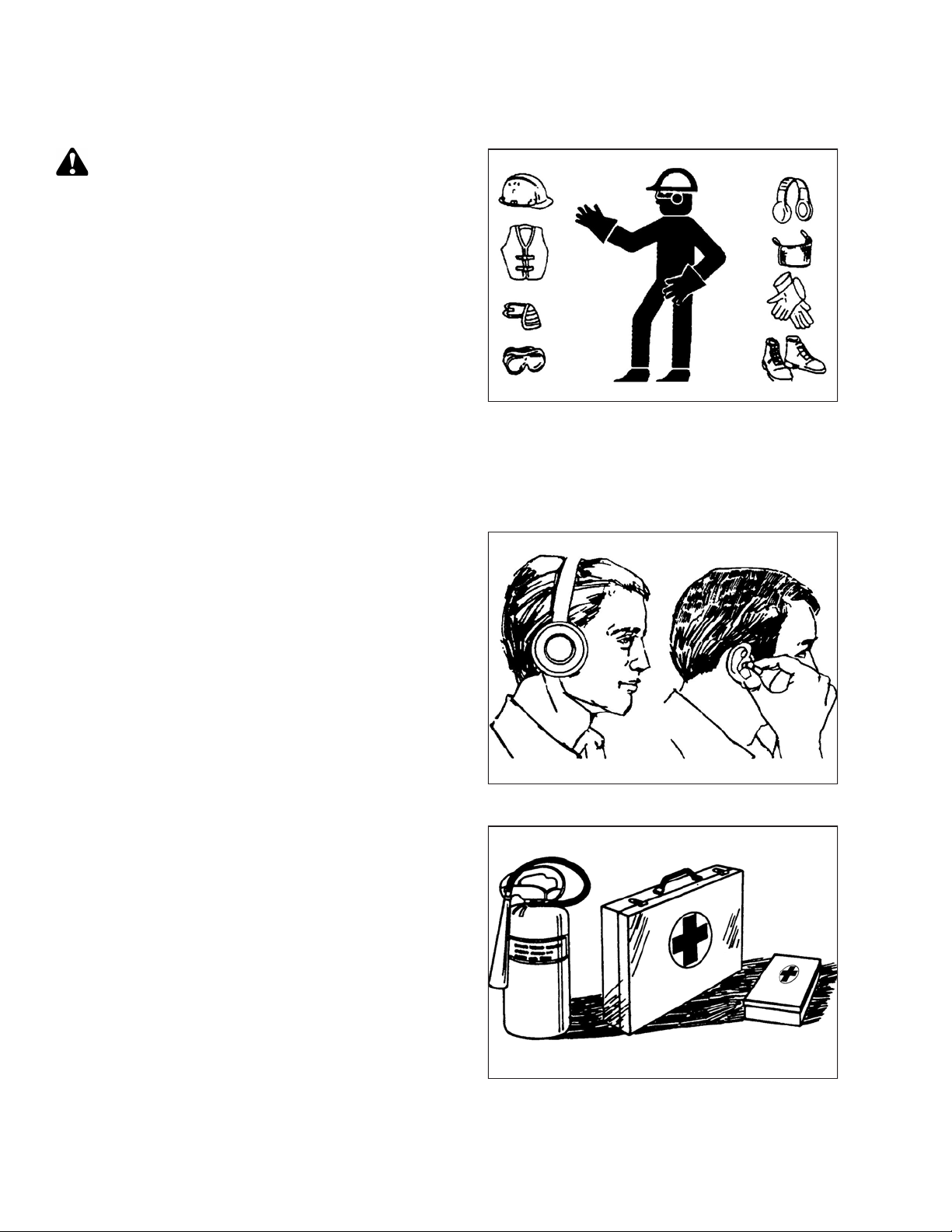
Protect yourself.
• When assembling, operating, and servicing machinery,
wear all protective clothing and personal safety devices
that could be necessary for job at hand. Do NOT take
chances. You may need the following:
• Hard hat
• Protective footwear with slip-resistant soles
• Protective glasses or goggles
• Heavy gloves
• Wet weather gear
• Respirator or filter mask
• Be aware that exposure to loud noises can cause hearing
impairment or loss. Wear suitable hearing protection
devices such as earmuffs or earplugs to help protect
against loud noises.
Figure 1.1: Safety Equipment
Figure 1.2: Safety Equipment
• Provide a first aid kit for use in case of emergencies.
• Keep a fire extinguisher on the machine. Be sure fire
extinguisher is properly maintained. Be familiar with its
proper use.
• Keep young children away from machinery at all times.
• Be aware that accidents often happen when Operator is
tired or in a hurry. Take time to consider safest way.
Never ignore warning signs of fatigue.
Figure 1.3: Safety Equipment
214735 2 Revision A
Page 13
1000007
1000008
1000009
SAFETY
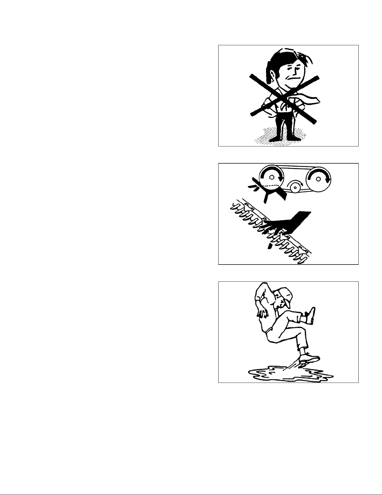
• Wear close-fitting clothing and cover long hair. Never
wear dangling items such as scarves or bracelets.
• Keep all shields in place. NEVER alter or remove safety
equipment. Make sure driveline guards can rotate
independently of shaft and can telescope freely.
• Use only service and repair parts made or approved by
equipment manufacturer. Substituted parts may not meet
strength, design, or safety requirements.
• Keep hands, feet, clothing, and hair away from moving
parts. NEVER attempt to clear obstructions or objects
from a machine while engine is running.
• Do NOT modify machine. Unauthorized modifications
may impair machine function and/or safety. It may also
shorten machine’s life.
Figure 1.4: Safety around Equipment
• To avoid bodily injury or death from unexpected startup of
machine, ALWAYS stop the engine and remove the key
from the ignition before leaving the operator’s seat for
any reason.
• Keep service area clean and dry. Wet or oily floors are
slippery. Wet spots can be dangerous when working with
electrical equipment. Be sure all electrical outlets and
tools are properly grounded.
• Keep work area well lit.
• Keep machinery clean. Straw and chaff on a hot engine is
a fire hazard. Do NOT allow oil or grease to accumulate
on service platforms, ladders, or controls. Clean
machines before storage.
• NEVER use gasoline, naphtha, or any volatile material for
cleaning purposes. These materials may be toxic and/or
flammable.
• When storing machinery, cover sharp or extending
components to prevent injury from accidental contact.
Figure 1.5: Safety around Equipment
Figure 1.6: Safety around Equipment
214735 3 Revision A
Page 14
1000020
1000019
SAFETY
1.3 Tire Safety
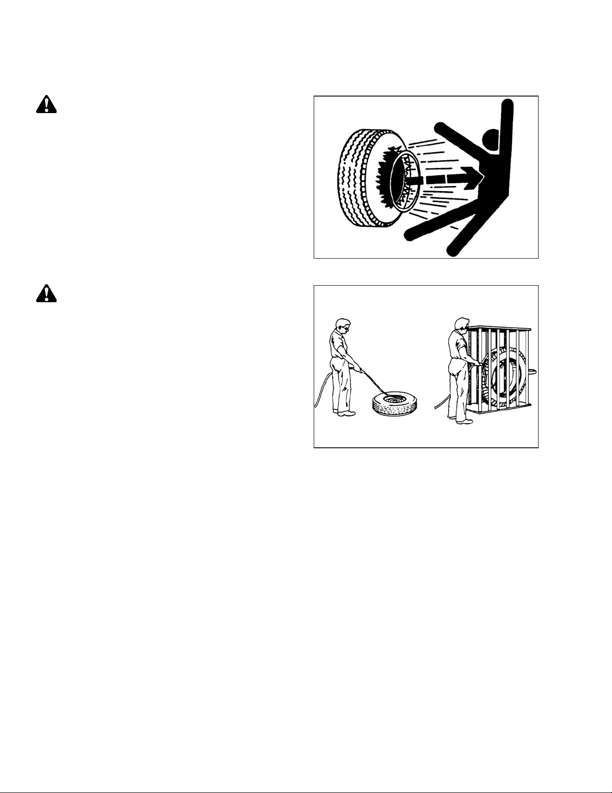
WARNING
• Service tires safely.
• A tire can explode during inflation which could cause
serious injury or death.
• Follow proper procedures when mounting a tire on a
wheel or rim. Failure to do so can produce an
explosion that may result in serious injury or death.
WARNING
• Do NOT stand over tire. Use a clip-on chuck and
extension hose.
Figure 1.7: Overinflated Tire
• Do NOT exceed maximum inflation pressure indicated
on tire label.
• Replace tires that have defects.
• Replace wheel rims that are cracked, worn, or
severely rusted.
• Never weld a wheel rim.
• Never use force on an inflated or partially inflated tire.
• Make sure tire is correctly seated before inflating to
operating pressure.
• If tire is not correctly positioned on rim or is overinflated, tire bead can loosen on one side causing air
to escape at high speed and with great force. An air leak of this nature can thrust tire in any direction
endangering anyone in area.
• Make sure all air is removed from tire before removing tire from rim.
• Do NOT remove, install, or repair a tire on a rim unless you have proper equipment and experience to
perform job.
• Take tire and rim to a qualified tire repair shop.
Figure 1.8: Safely Inflating Tire
214735 4 Revision A
Page 15
1000015
1000016
1000017
SAFETY
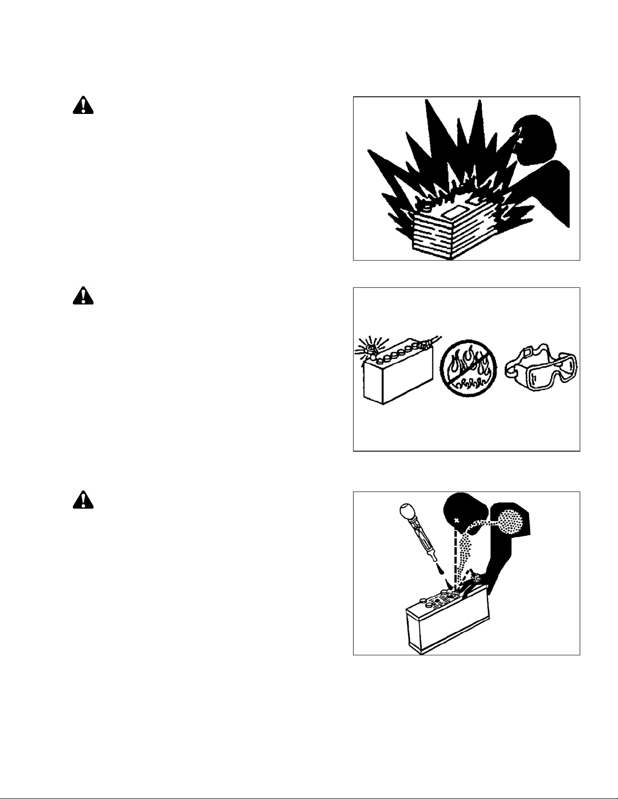
1.4 Battery Safety
WARNING
• Keep all sparks and flames away from batteries, as a
gas given off by electrolyte is explosive.
• Ventilate when charging in enclosed space.
WARNING
• Wear safety glasses when working near batteries.
• Do NOT tip batteries more than 45° to avoid
electrolyte loss.
Figure 1.9: Safety around Batteries
• Battery electrolyte causes severe burns. Avoid
contact with skin, eyes, or clothing.
• Electrolyte splashed into eyes is extremely
dangerous. Should this occur, force eye open, and
flood with cool, clean water for 5 minutes. Call a
doctor immediately.
• If electrolyte is spilled or splashed on clothing or
body, neutralize it immediately with a solution of
baking soda and water, then rinse with clear water.
WARNING
• To avoid injury from spark or short circuit, disconnect
battery ground cable before servicing any part of
electrical system.
• Do NOT operate engine with alternator or battery
disconnected. With battery cables disconnected and
engine running, a high voltage can be built up if
terminals touch frame. Anyone touching frame under
these conditions would be severely shocked.
• When working around storage batteries, remember
that all of the exposed metal parts are live. Never lay a
metal object across terminals because a spark or
short circuit will result.
Figure 1.10: Safety around Batteries
Figure 1.11: Safety around Batteries
• Keep batteries out of reach of children.
214735 5 Revision A
Page 16
10176211017621
A
1017622
A
SAFETY
1.5 Welding Precaution
WARNING
It is very important that correct procedures be followed when welding anything connected to the
windrower. If procedures are not followed, it could result in severe damage to sensitive, expensive
electronics. Even if complete failure of a module doesn’t happen immediately, it is impossible to know
what effect high current could have with regard to future malfunctions or shorter lifespan.
Due to the number of connectors, components to be welded should be removed from the windrower whenever
possible rather than welded in place. When work needs to be completed on a header, disconnect the header
completely from the windrower before welding. These same guidelines apply to plasma cutting, or any other high
current electrical operation performed on the machine.
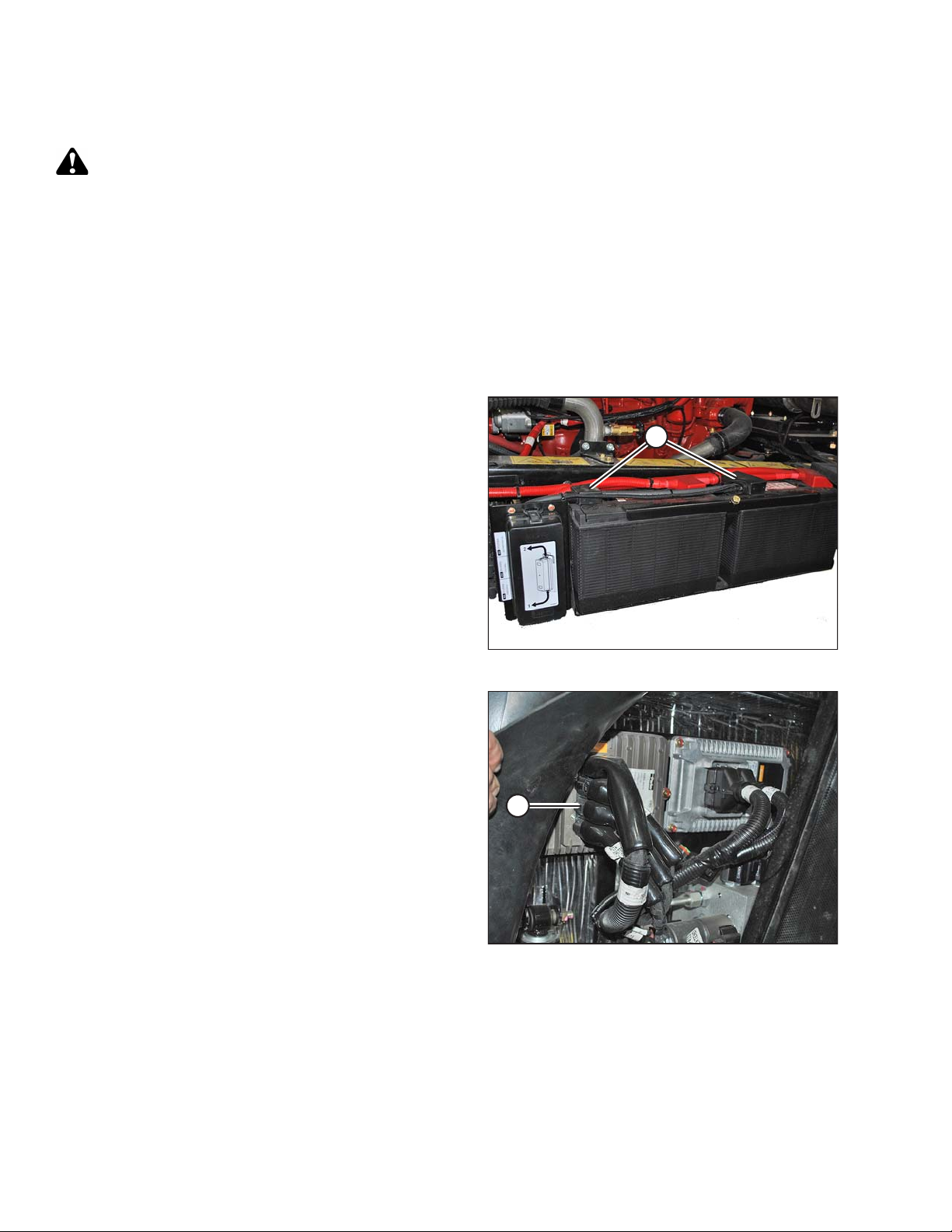
The following items need to be disconnected:
• Negative battery terminals (A) (two connections)
IMPORTANT:
Always disconnect the battery terminals first, and
reconnect them last.
• Master controller (A)
Four connectors: P231, P232, P233, and P234
Location: Behind cab, near header lift/fan manifold
To disconnect the connectors, press the two outer tabs,
and pull the connector away from master controller.
IMPORTANT:
When reconnecting these connectors, double-check that
the connectors are fully seated into the master controller,
and that the two locking tabs on each end of all four
connectors have popped outward. If the tabs are not
popped outward, the connector is not fully seated.
IMPORTANT:
Do NOT power up or operate the windrower until these
connectors are locked into place.
Figure 1.12: Negative Terminals
Figure 1.13: Master Controller
214735 6 Revision A
Page 17
1017623
A
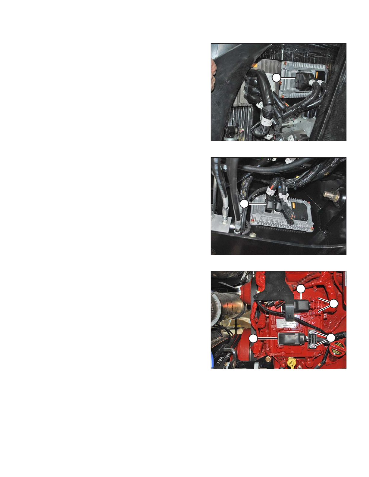
• Firewall extension module (A)
1017624
A
1019753
A
B
C
C
Two connectors: P235 and P236
Location: Behind cab, near header lift/fan manifold.
To disconnect, use a small 3–6 mm (1/8–1/4 in.) blade
screwdriver to insert into the connector’s locking tab.
Gently pry upward (no more than 6 mm [1/4 in.]) to unlock
the connector tab, and then pull the connector away from
the module.
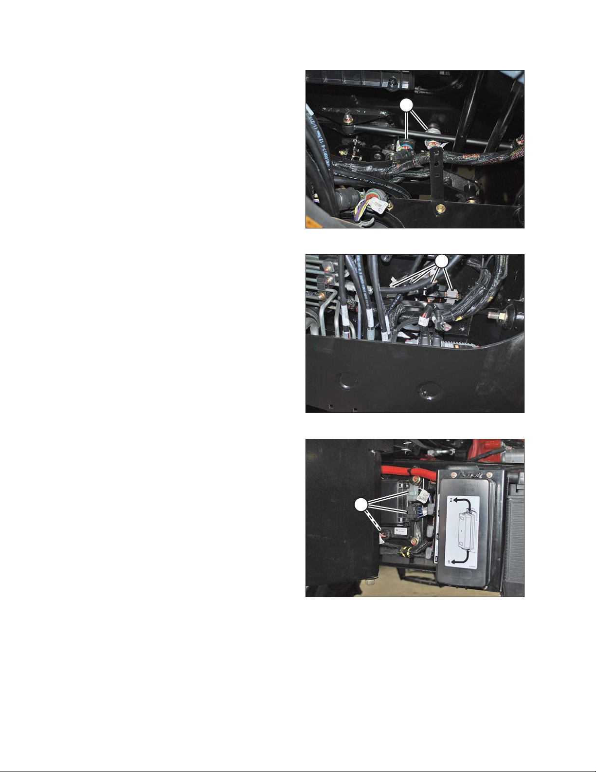
• Chassis extension module (A)
Two connectors: P247 and P248
Location: Under cab, inside left frame rail
To disconnect, use a small 3–6 mm (1/8–1/4 in.) blade
screwdriver to insert into the connector’s locking tab.
Gently pry upward (no more than 6 mm [1/4 in.]) to unlock
the connector tab, and then pull the connector away from
the module.
SAFETY
Figure 1.14: Firewall Extension Module
• Engine Control Module (ECM)
Two connectors for Cummins: P100 (A) and J1 Cummins
Proprietary ECM Connector (B)
Location: On engine
To disconnect, pull the rubber boot off the cover, unlock
the latch, and undo the main over-center latch. Remove
strain relief bolts (C) so the connectors can be pulled
away from the ECM.
IMPORTANT:
Be sure to disconnect both connectors. Note connector
locations.
IMPORTANT:
Be sure to reconnect connectors in the proper locations.
Do NOT cross connect.
Figure 1.15: Chassis Extension Module
Figure 1.16: Engine Control Module
214735 7 Revision A
Page 18
1017626
A
NOTE:
1017627
A
1017628
A
To disconnect the remaining circular Deutsch
connectors, rotate outer collar counterclockwise.
• Cab connectors (A)
Two round connectors: C1 and C2
Location: Under cab
• Roof connectors (A)
Four connectors: C10, C12, C13, and C14
Location: Under cab at base of left cab post
SAFETY
Figure 1.17: Cab Connectors
• Chassis relay module (A)
Three connectors: P240, P241, and P242
Location: Outside left frame rail near batteries
Figure 1.18: Roof Connectors
Figure 1.19: Chassis Relay Module
214735 8 Revision A
Page 19
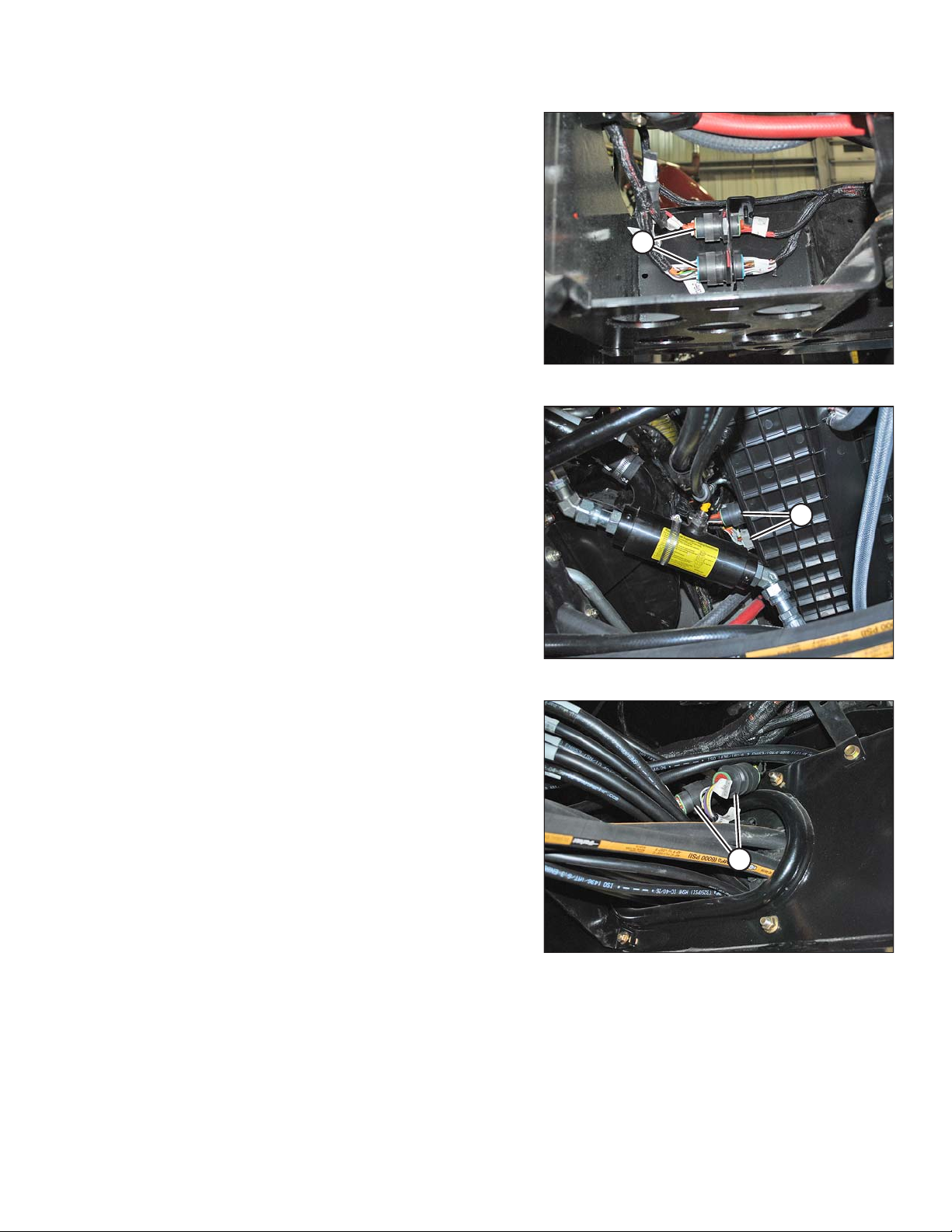
1017657
A
• Engine harness (A)
1017630
A
1017631
A
Two round connectors: C30 and C31
Location: Inside left frame rail, at rear of windrower
• Air conditioning (A/C) box connectors (A)
Two connectors: C15 and C16
Location: Rear of A/C box
SAFETY
Figure 1.20: Engine Harness
• Wheel motor connectors (A)
Two round connectors: C25 and C26
Location: Under center of frame, just behind front
cross member
Figure 1.21: A/C Box Connectors
Figure 1.22: Wheel Motor Connectors
214735 9 Revision A
Page 20

SAFETY
IMPORTANT:
To connect circular Deutsch connectors without bending the pins, align connector with receptacle before attempting
to reconnect.
To align the connectors:
1. Observe the channel cuts and mating channel protrusions on the inner part of the circular walls of the
connectors.
2. Face the mating connectors to each other, and rotate connectors so that channels are aligned.
3. Press connectors together while turning the outer connector clockwise until collar locks.
214735 10 Revision A
Page 21

SAFETY
1.6 Engine Safety
WARNING
Do NOT use aerosol starting aids such as ether. Such use could result in an explosion and personal injury.
CAUTION
• On initial start-up of a new, serviced, or repaired engine, always be ready to stop the engine in order to
stop an overspeed. This may be accomplished by shutting off the air and/or fuel supply to the engine.
• Do NOT bypass or disable automatic shutoff circuits. The circuits are provided in order to help prevent
personal injury. The circuits are also provided in order to help prevent engine damage. Refer to the
technical manual for repairs and adjustments.
• Inspect the engine for potential hazards.
• Before starting the engine, ensure that no one is on, underneath, or close to the engine. Ensure that
people clear the area.
• All protective guards and all protective covers must be installed if the engine must be started in order
to perform service procedures.
• To help prevent an accident that is caused by parts in rotation, work around parts carefully.
• If a warning tag is attached to engine start switch or to controls, do NOT start engine or move controls.
Consult with person who attached warning tag before engine is started.
• Start engine from operator’s compartment. Always start engine according to procedure that is
described in Starting Engine section of operator’s manual. Knowing correct procedure will help to
prevent major damage to engine components and prevent personal injury.
• To ensure that the jacket water heater (if equipped) and/or lubricant oil heater (if equipped) is working
correctly, check the water temperature gauge and/or oil temperature gauge during heater operation.
• Engine exhaust contains products of combustion, which can be harmful to your health. Always start
the engine and operate the engine in a well-ventilated area. If the engine is started in an enclosed area,
vent the engine exhaust to the outside.
• Engine exhaust gases become very hot during operation and can burn people and common materials.
Stay clear of the rear of machine and avoid exhaust gases when engine is running.
NOTE:
The engine may be equipped with a device for cold starting. If the engine will be operated in very cold conditions,
then an additional cold starting aid may be required.
1.6.1 High-Pressure Rail
CAUTION
• Contact with high-pressure fuel may cause fluid penetration and burn hazards. High-pressure fuel
spray may cause a fire hazard. Failure to follow these instructions may cause personal injury or death.
• Before disconnecting fuel lines or any other components under high-pressure between the fuel pump
and high-pressure common rail fuel system, confirm that the fuel pressure is relieved.
214735 11 Revision A
Page 22

SAFETY
1.6.2 Engine Electronics
WARNING
Tampering with electronic system installation or original equipment manufacturer (OEM) wiring
installation can be dangerous and could result in personal injury or death and/or engine damage.
WARNING
Electrical Shock Hazard. The electronic unit injectors use DC voltage. The engine control module (ECM)
sends this voltage to the electronic unit injectors. Do NOT come in contact with the harness connector for
the electronic unit injectors while engine is operating. Failure to follow this instruction could result in
personal injury or death.
This engine has a comprehensive, programmable engine monitoring system. The ECM has the ability to monitor
engine operating conditions. If conditions exceed the allowable range, the ECM will initiate immediate action.
The following actions are available for engine monitoring control:
• Warning
• Derate
• Shut down
The following monitored engine operating conditions have the ability to limit engine speed and/or engine power:
• Engine coolant temperature
• Engine oil pressure
• Engine speed
• Intake manifold air temperature
• Diesel exhaust fluid (DEF) system performance
• Aftertreatment system performance
214735 12 Revision A
Page 23
1000694
SAFETY
1.7 Safety Signs
• Keep safety signs clean and legible at all times.
• Replace safety signs that are missing or illegible.
• If original part on which a safety sign was installed is
replaced, be sure repair part also bears current
safety sign.
• Safety signs are available from your MacDon Dealer.
Figure 1.23: Operator’s Manual Decal
214735 13 Revision A
Page 24

Page 25
2 Unloading the Windrower
1016187
A
B
C
C
2.1 Using One Forklift to Unload Windrower
CAUTION
Equipment used for unloading must meet or exceed the specified requirements. Using inadequate
equipment may result in chain breakage, vehicle tipping, or machine damage.
Table 2.1 Lifting Vehicle Requirements
Minimum Capacity
Minimum Fork Length
IMPORTANT:
Forklifts are normally rated for a load located 610 mm (24 in.) ahead of the back end of the forks. To obtain forklift
capacity at 122.2 cm (48 in.), check with your forklift distributor.
1. Move the trailer onto level ground and block the trailer wheels.
2. Set forklift tines to the widest possible setting.
1
7037 kg (15,500 lb.)
198.1 cm (78 in.)
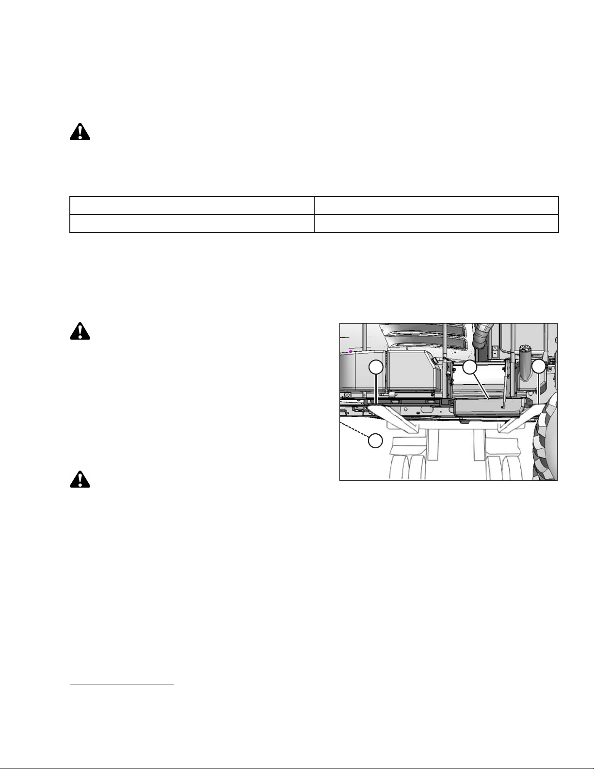
CAUTION
Ensure forks do NOT contact or lift on fuel tank (A) or
engine oil pan (B) (not shown).
3. Position forklift from opposite side of fuel tank, and
position forks (C) under windrower frame with the fuel
tank (A) between the forks.
NOTE:
The windrower’s center of gravity is approximately
157.5 cm (62 in.) rearwards from the center of the
drive wheel.
WARNING
Ensure the forks extend beyond the far side of
the frame.
Figure 2.1: Windrower on Trailer
4. Lift until windrower is clear of the trailer deck.
5. Back forklift slowly away from trailer until the windrower is clear of the trailer deck.
6. Lower unit slowly to the ground. If the ground is soft, place wooden blocks under the front shipping stands.
7. Carefully back forklift away from windrower.
8. Check windrower for shipping damage, and check shipment for missing parts.
9. In case of shipping damage or missing parts, confirm that serial number matches shipping manifest, then
contact MacDon immediately with any damage or shortage claims.
1. At 122.2 cm (48 in.) from back end of forks.
214735 15 Revision A
Page 26

Page 27
3 Assembling the Windrower
1014559
A
C
B
1014555
A
B
C
1014555
A
B
C
1014555
A
B
C
Perform all procedures in this chapter in the order in which they are listed.
3.1 Lowering Steps
Lowering the steps allows safe and easy access to the cab where some assembly hardware was stored for
shipping purposes.
Lower steps from shipping position to working position as follows:
NOTE:
Left side shown, right side opposite.
1. Remove stop bolt (A) and discard.
2. Loosen pivot bolts (B) at both sides of step (C).
3. Lower step (A) to working position.
4. Ensure clips (B) are engaged in step.
5. Tighten pivot bolts (C) to 90–100 Nm (66–73 lbf·ft).
Figure 3.1: Left Step – Shipping Position
Figure 3.2: Left Step – Working Position
214735 17 Revision A
Page 28
1022861
A
ASSEMBLING THE WINDROWER
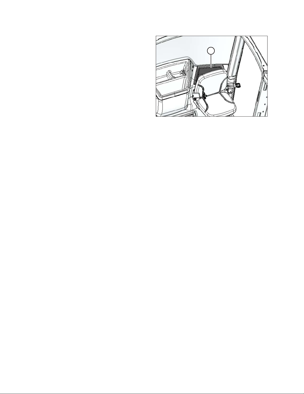
6. Retrieve bag containing drive wheel nuts from the
storage compartment (A) behind the training seat.
Figure 3.3: Storage Compartment
214735 18 Revision A
Page 29
1022761
A
1018731
A
1022864
A
ASSEMBLING THE WINDROWER
3.2 Installing Caster Wheels
Some shipping configurations come with caster wheels removed. Follow this procedure to install caster wheels if
required.
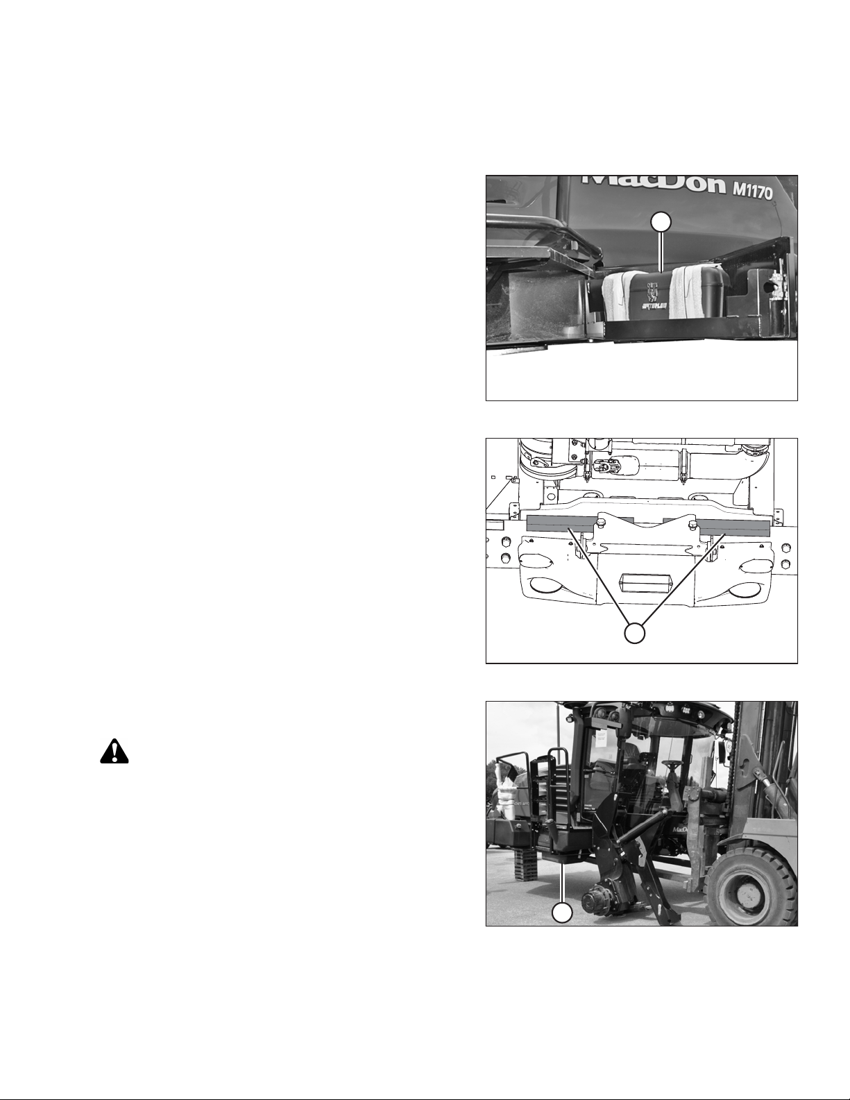
1. Retrieve toolbox (A) from the storage compartment, and
remove banding.
NOTE:
Use ignition key to unlock storage compartment.
2. Retrieve hardware from the toolbox (A).
Figure 3.4: Toolbox
3. Remove banding and blocking (A) securing walking
beam to frame.
4. Retrieve caster wheel assemblies from shipment.
5. Using a forklift, approach windrower from the front and
slide forks under frame.
CAUTION
Ensure forks do NOT contact fuel tank (A) and that forks
lift on windrower frame.
6. Raise windrower approximately 152 cm (60 in.) off the
ground. Place suitable stands under the drive wheel
legs and rear frame, and lower windrower onto stands
to partially unload the forks.
Figure 3.5: Windrower Rear
Figure 3.6: Lifting Windrower
214735 19 Revision A
Page 30
1022767
A
B
C
D
1022865
A
B
C
D
1022863
A
B
C
D
E
ASSEMBLING THE WINDROWER
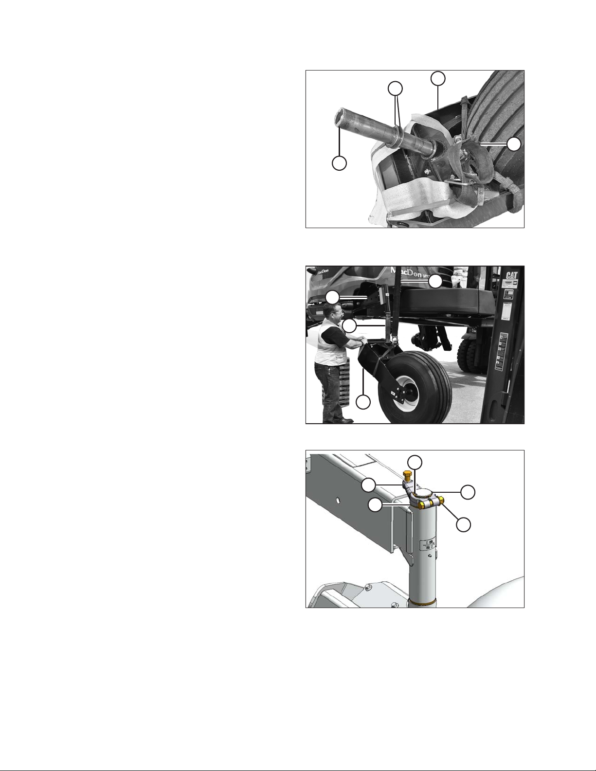
7. Attach a sling (B) to caster assembly (A).
8. Retrieve two washers (C) from the toolbox and place
them on the caster wheel spindle (D).
9. If caster assembly is on a pallet, remove banding and
shipping material securing the assembly (A) to pallet.
10. Attach the sling (A) on the caster assembly (B) to a
suitable lifting device.
11. Tilt walking beam (C) and maneuver caster
assembly (B) so that spindle (D) can be installed onto
walking beam (C).
Figure 3.7: Caster Wheel Assembly in Shipping
Configuration
12. Install the flat washer (A) onto the spindle.
13. Install key (B) and arm (C) onto spindle, ensuring that
arm is positioned so there is no clearance at the top and
bottom of the walking beam extension.
14. Install retaining ring (D).
15. Tighten nut (E) and torque to 190–200 Nm
(140–147 lbf·ft).
16. Remove sling from caster assembly.
17. Repeat Steps 7, page 20 to 16, page 20 for second
caster assembly.
Figure 3.8: Installing Caster Assembly
Figure 3.9: Caster Arm
214735 20 Revision A
Page 31

1022781
A
B
C
1022892
A
C
B
ASSEMBLING THE WINDROWER
3.3 Installing Drive Wheels
IMPORTANT:
Windrower must be supported off the ground with stands.
1. Using a forklift, lift cab-end of windrower to
approximately 130 cm (51 in.) (B) off the ground,
enough to position the drive wheel assembly (A). Place
a stand (C) under windrower frame.
2. Clean mounting surface on wheel drive and rim.
CAUTION
Figure 3.10: Supporting Windrower
Use a lifting device capable of supporting a minimum of
907 kg (2000 lb.) to lift the wheel assembly.
3. Position pallet jack (A) or equivalent under tire and raise
slightly.
4. Locate drive wheel against the wheel drive hub so
air valve (B) is on the outside and the tire tread (C)
points forward with the windrower in cab-forward
orientation.
NOTE:
For turf tires (diamond tread pattern), be sure arrow on
sidewall points in forward rotation with windrower in
cab-forward.
Figure 3.11: Drive Wheel
214735 21 Revision A
Page 32

1011218
A
1
3
4
5
6
7
8
9
10
2
ASSEMBLING THE WINDROWER
5. Position wheel to line up holes in rim with studs on hub
and push wheel onto hub.
6. Install wheel nuts (A).
IMPORTANT:
To avoid damage to wheel rims and studs, do NOT use
an impact wrench. Threads must be clean and dry. Do
NOT apply lubricant or anti-seize compound. Do NOT
overtighten the wheel nuts.
7. Torque drive wheel nuts to 510 Nm (375 lbf·ft) using the
tightening sequence shown.
IMPORTANT:
Use only manufacturer-specified nuts (MD #205397).
8. Repeat tightening sequence two additional times,
ensuring the specified torque is achieved each time.
Figure 3.12: Tightening Sequence
9. Lower jack and move away from work area.
10. Raise windrower, remove stand, and lower windrower to ground.
11. Repeat Steps 2, page 21 to 8, page 22 for the other drive wheel.
12. Repeat torque procedure every hour of operation until two consecutive checks confirm that there is no
movement of the nuts.
214735 22 Revision A
Page 33

1022868
B
A
C
1022788
A
ASSEMBLING THE WINDROWER
3.4 Repositioning Right Leg
The right (cab-forward) leg requires repositioning from shipping to field configuration.
CAUTION
Do NOT open the right cab-forward door when the right leg is in shipping configuration. If glass door
contacts the leg, it may result in broken glass and/or damaged door seal.
1. Using a forklift, lift front of windrower. Place a stand (A)
(or equivalent) to support front of windrower and to
keep right wheel (B) off the ground.
2. Slowly lower windrower onto a stand (A).
3. Place a pallet jack (C) (or equivalent) under the right
wheel (B), and raise pallet jack enough to take the
weight off the right wheel.
4. Remove shipping tag and wire (A) from traction drive
hoses under the cab.
Figure 3.13: Supporting Right Leg of Windrower
Figure 3.14: Under Windrower Cab
214735 23 Revision A
Page 34

1022807
A
1022808
A
B
1022871
A
ASSEMBLING THE WINDROWER
5. Remove two bolts (A), washers, and nuts from frame.
6. Adjust lift height until pin (A) is loose. Extract pin from
front of frame with a slide hammer (B) (MD #209816)
(tool required due to limited space in front of fuel tank).
Instructions are included with the tool.
NOTE:
Removing the pins will be difficult if weight is still on
the leg.
Figure 3.15: Windrower Right Leg
7. Repeat for second pin.
8. Move leg outwards to expose one hole (A) in frame.
Figure 3.16: Slide Hammer
Figure 3.17: Repositioning Right Leg
214735 24 Revision A
Page 35

1022811
A
B
1022807
A
ASSEMBLING THE WINDROWER
9. Align holes at pin locations and use the slide
hammer (B) to reinstall pins (A). If necessary, adjust
jack to prevent damage to the outer edges of the pins.
10. Secure pins with bolts (A), washers, and nuts. Torque
nuts to 136 Nm (100 lbf·ft).
11. Lower pallet jack and move it from work area.
12. Support the windrower with forklift, remove stand, and
lower windrower to ground.
Figure 3.18: Leg Pin
Figure 3.19: Right Leg
214735 25 Revision A
Page 36

1022900
1018697
A
A
B
C
1018731
A
ASSEMBLING THE WINDROWER
3.5 Repositioning Caster Wheels
A narrow caster tread width is better suited for smaller headers because it allows more space for the uncut crop
and provides more maneuverability around poles, irrigation inlets, and other obstacles. A wider caster tread width
reduces runover in heavy crops that produce large windrows.
1. Lift windrower with forklift to take most of the weight off
casters.
Figure 3.20: Supporting Windrower
2. Remove four bolts and washers (A), shock support
brackets (B), and slow moving vehicle (SMV) sign
support bracket (C) from walking beam.
3. Retain hardware and support brackets (B) and (C) for
installation later.
NOTE:
There is one SMV support bracket (C) preinstalled on
shock support brackets (B) at the left cab-forward
walking beam.
4. If not done yet, remove banding and blocking (A)
securing walking beam to frame.
Figure 3.21: Walking Beam
Figure 3.22: Windrower Rear
214735 26 Revision A
Page 37

1022816
B
A
C
1022817
A
B
C
1022821
A
B
ASSEMBLING THE WINDROWER
5. Rotate the caster so the wheel (A) is parallel to the
walking beam to assist with moving the extensions. Pull
walking beam extension (B) out to desired position and
line up bolt holes.
NOTE:
The walking beam extension (B) can be adjusted into
three working positions.
6. Install two M24 x 60 bolts and washers (C) on bottom of
beam. Do NOT tighten.
7. Install two M24 x 60 bolts coated with anti-seize
compound and M24 flat washers (A) from the toolbox in
the outboard side of the walking beam. Do NOT fully
tighten.
NOTE:
Depending on the extent of walking beam position,
outboard bolts may need to be installed first.
Figure 3.23: Walking Beam Extension
8. Place support brackets (B) onto walking beam as
shown and secure with two M24 x 60 bolts coated with
anti-seize compound and M24 flat washers (C).
Do NOT fully tighten.
IMPORTANT:
Ensure support bracket plate (B) is parallel or is
installed straight.
9. Tighten bolts as follows:
a. Snug bottom bolts (A), then snug back bolts (B).
b. Torque back bolts (B) to 745–770 Nm
(550–570 lbf·ft).
c. Torque bottom bolts (A) to 745–770 Nm
(550–570 lbf·ft).
IMPORTANT:
Torque bolts after first 5 hours of operation, and then
again after 10 hours.
Figure 3.24: Anti-Shimmy Brackets
Figure 3.25: Walking Beam Bolts
214735 27 Revision A
Page 38

1013124
=
=
ASSEMBLING THE WINDROWER
10. Repeat Steps 2, page 26 to 9, page 27 at opposite end
of walking beam, ensuring that casters are spaced
equally from center of windrower.
11. Lower windrower to ground.
Figure 3.26: Walking Beam Adjustment
214735 28 Revision A
Page 39

1022660
B
A
C
D
E
1020058
A
B
C
D
1020059
A
B
C
D
ASSEMBLING THE WINDROWER
3.6 Installing Caster Anti-Shimmy Dampeners
1. Retrieve anti-shimmy dampeners and hardware from
bag in toolbox.
2. If unit was shipped with casters installed, then complete
the following procedure. Otherwise, proceed to step 3,
page 29.
a. Remove retaining ring (A).
b. Remove and discard yellow spacer (B).
c. Retrieve key and arm from the toolbox.
d. Install key and arm (D), and secure with retaining
ring (E) on the caster shaft as shown.
e. Tighten nut (C), and torque to 190–200 Nm
(140–147 lbf·ft).
Figure 3.27: Anti-Shimmy Arm – Left Side
3. Attach barrel end of anti-shimmy dampener (A) to
forward hole in support (B) with one M16 x 75 flange
head bolt (C) and one M16 tech loc nut (D). Install bolt
from under support. Do NOT fully tighten.
Figure 3.28: Anti-Shimmy System – Left Side
4. Attach barrel end of second anti-shimmy dampener (A)
to support (B) at aft hole location with one M16 x 90
flange head bolt and M16 tech loc nut (C). Install bolt
from under support. Do NOT fully tighten.
5. Rotate caster so that arm (D) is aligned with
walking beam.
Figure 3.29: Anti-Shimmy System – Left Side
214735 29 Revision A
Page 40

1016210
A
C
B
D
ASSEMBLING THE WINDROWER
6. Attach rod ends of anti-shimmy dampeners to arm with
M16 x 90 flange head bolt (A) and three hardened
washers (B).
NOTE:
These washers (B) are stamped with L9 for
identification.
7. Torque bolt (A) to 244 Nm (180 lbf·ft).
8. Install jam nut (C) and torque to 136–140 Nm
(100–103 lbf·ft).
9. Tighten bolts (D) at barrel end of anti-shimmy
dampeners, and torque to 136–140 Nm
(100–103 lbf·ft).
IMPORTANT:
Maintain arm parallel to walking beam while tightening.
Do NOT overtighten.
10. Repeat Steps 2, page 29 to 9, page 30 for opposite end
of walking beam.
Figure 3.30: Anti-Shimmy System – Left Side
IMPORTANT:
Torque bolts after first 5 hours of operation, and then
again after 10 hours.
214735 30 Revision A
Page 41

1018596
A
B
1016246
A
C
B
ASSEMBLING THE WINDROWER
3.7 Installing Windshield Access Step
The windshield access step is secured on the railing of the right side platform (cab-forward).
1. Remove windshield access step (A) from shipping
location on right platform, and remove packing
materials (B) from step and railing.
2. Retrieve the three self-tapping bolts from a bag in the
toolbox.
NOTE:
Use ignition key to unlock toolbox compartment.
Figure 3.31: Step in Shipping Position
3. Position step (A) on right leg at forward end of platform
as shown.
4. Install two M10 x 20 hex head screws (B) through top of
step, but do NOT tighten.
5. Install one M10 x 20 hex head screw (C) through step
support.
6. Tighten and torque screws to 54–61 Nm (40–45 lbf·ft).
Figure 3.32: Windshield Access Step
214735 31 Revision A
Page 42

1014676
A
B
1014676
A
B
C
1014676
A
B
C
1014676
A
B
C
1014674
A
B
ASSEMBLING THE WINDROWER
3.8 Positioning Mirror Arms
The mirror/light support arms require repositioning from shipping position to working position.
1. Loosen retaining nut (A) and pivot nut (B) on support
arm (C).
2. Swivel support arm (C) forward 90 degrees from
shipping position to working position.
Figure 3.33: Mirror Arm in Shipping Position
3. Tighten retaining nut (A) to 37–41 Nm (28–30 lbf·ft).
4. Tighten pivot nut (B) to 24–27 Nm (18–20 lbf·ft).
5. Repeat above steps for opposite mirror.
Figure 3.34: Mirror Arm in Working Position
214735 32 Revision A
Page 43

1014590
A
B
C
1018716
A
B
C
ASSEMBLING THE WINDROWER
3.9 Installing Slow Moving Vehicle (SMV) Signs
To install the SMV sign onto the mirror/light support and walking beam, proceed as follows:
1. Retrieve SMV signs from inside cab and hardware from toolbox.
NOTE:
Use ignition key to unlock cab door and toolbox compartment.
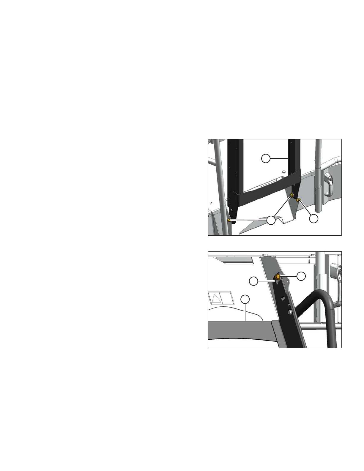
2. Position sign (A) on existing bracket (B) as shown on
right cab-forward side mirror/light support, and secure
with two M6 x 20 hex head bolts (C) and M6 lock nuts.
IMPORTANT:
Ensure SMV sign does NOT cover brake light.
3. Locate support (A) on left cab-forward side of
walking beam.
4. Position sign (B) on support (A) as shown, and secure
with two M6 x 20 hex head bolts (C) and M6 lock nuts.
Figure 3.35: Right Side Mirror/Light Support
Figure 3.36: Walking Beam Left Side
214735 33 Revision A
Page 44

1019824
A
ASSEMBLING THE WINDROWER
3.10 Replacing Speed Identification Symbol (SIS) Decal (US Only)
This topic applies to windrowers used in the United States only.
1. Locate the existing SIS decal bracket on the left
mirror/lighting arm.
2. Wipe the existing decal with a clean cloth to remove dirt
and grease.
3. Apply the 30 mile/h SIS decal (A) (MD #208900) over
the existing 45 km/h decal.
Figure 3.37: SIS Decal (US Only)
214735 34 Revision A
Page 45

ASSEMBLING THE WINDROWER
3.11 Installing Rear Ballast Package
When windrower operates with a heavy header, ballast needs to be added to the aft end. Use the following table to
determine the amount of ballast required.
Refer to 4.1.10 Checking Tire Pressures, page 52 for proper tire pressures when operating with the applicable
header.
Table 3.1 Ballast Specifications
Header
Type
D125X
D130XL
D130XL
D130XL
D135XL
D135XL
D135XL
D135XL
D135XL
Description
7.6 m (25 ft.), single reel,
double knife, timed
9.1 m (30 ft.), single reel,
double knife, timed
9.1 m (30 ft.), single reel,
double knife, timed
9.1 m (30 ft.), single reel,
double knife, timed
10.6 m (35 ft.), single reel,
double knife, untimed
10.6 m (35 ft.), single reel,
double knife, untimed
10.6 m (35 ft.), single reel,
double knife, untimed
10.6 m (35 ft.), double reel,
double knife, untimed
10.6 m (35 ft.), double reel,
double knife, untimed
Installed Options
—
Base 0 0 0
Transport 1 0 0
Transport + upper cross
auger + vertical knives
Base 1 1 0
Transport 1 1 B6047
Transport + upper cross
auger + vertical knives
Base 1 1 0
Transport 1 1 B6047
Base Kit
00 0
1 0 B6047
1 2 B6047
Additional
Kits
Additional
Float
Springs
D135XL
D140XL
D140XL
D140XL
D145XL
214735 35 Revision A
10.6 m (35 ft.), double reel,
double knife, untimed
12.2 m (40 ft.), double reel,
double knife, untimed
12.2 m (40 ft.), double reel,
double knife, untimed
12.2 m (40 ft.), double reel,
double knife, untimed
13.7 m (45 ft.), double reel,
double knife, untimed
Transport + upper cross
auger + vertical knives
Base 1 1 0
Transport 1 1 B6047
Transport + upper cross
auger + vertical knives
Base 1 1 B6047
1 2 B6047
1 2 B6047
Page 46

1019838
A
B
ASSEMBLING THE WINDROWER
Table 3.1 Ballast Specifications (continued)
Header
Type
D145XL
D145XL
Description
13.7 m (45 ft.), double reel,
double knife, untimed
13.7 m (45 ft.), double reel,
double knife, untimed
Installed Options
Transport 1 2 B6047
Transport + upper cross
auger + vertical knives
Base Kit
Additional
Kits
1 2 B6106
Additional
Float
Springs
NOTE:
• Each kit consists of eight weights and weighs 163 kg (360 lb.).
• Ballast not required for A Series Auger Headers and R1 Series Disc Headers.
To install rear ballast, follow these steps:
WARNING
To avoid bodily injury or death from unexpected startup of the machine, always stop the engine and
remove the key from the ignition before leaving the operator’s seat for any reason.
1. Refer to Table 3.1, page 35 to determine ballast to add to windrower.
2. Stop engine, and remove key.
3. Move latch (A) towards right cab-forward side of
windrower.
4. Grasp louver (B), and lift hood to open.
Figure 3.38: Engine Compartment Hood
214735 36 Revision A
Page 47

1022925
A
A
A
A
B
D
C
1022910
B
A
1022911
B
A
B
ASSEMBLING THE WINDROWER
5. Remove eight hex flange bolts (A).
6. Slightly pull light bezel assembly (B), and disconnect
plugs P215 (C) and P210 (D) from back of red tail/brake
lights inside bezel.
7. Remove light bezel assembly (B).
8. Separate light bezel assembly (A) by removing six hex
screws (B).
Figure 3.39: Rear Light Bezel
Figure 3.40: Bezel Assembly
NOTE:
• Retain center portion (A) of light bezel assembly for
reinstallation when rear ballast are removed.
• Install six hex screws (B) on side bezels for
safekeeping. These hex screws will be used when
reinstalling center portion of light bezel.
Figure 3.41: Bezel Assembly
214735 37 Revision A
Page 48

1013204
A
1022921
A
E
B
C
D
E
E
F
F
1018705
A
B
C
D
E
ASSEMBLING THE WINDROWER
9. Grasp hood by louver (A) and lower until hood
engages latch.
CAUTION
To avoid injury, keep fingers clear of weight bracket
when installing weights.
10. Install weights (A) from outboard side and slide to
middle of bracket on walking beam.
Figure 3.42: Engine Compartment
11. Install retaining bracket (B) on each side of weight
bundle.
IMPORTANT:
Ensure retaining bracket (B) engage slot (C) in bracket.
12. Install rod (D) through retaining bracket and weights
with spacers (E) as required.
13. Secure with nuts (F) and tighten.
IMPORTANT:
Ensure nuts (F) are flush with rod.
Figure 3.43: Weights Installed
Figure 3.44: Base Kit – 163 kg (360 lb.)
214735 38 Revision A
Page 49

1018706
A
B
C
D
E
1018707
A
B
C
D
1019838
A
B
ASSEMBLING THE WINDROWER
Figure 3.45: Two Sets – 326 kg (720 lb.)
Figure 3.46: Three Sets – 489 kg (1080 lb.)
14. Move latch (A) towards right cab-forward side of
windrower.
15. Grasp louver (B), and lift hood to open.
Figure 3.47: Engine Compartment Hood
214735 39 Revision A
Page 50

1022915
A
C
B
E
D
1013204
A
ASSEMBLING THE WINDROWER
16. Bring left side bezel (A) close to frame and connect plug
P215 to back of red tail/brake light.
17. Loosely attach left side bezel (A) to frame with four hex
flange bolt (B).
18. Repeat Steps 16, page 40 to 17, page 40 attaching
plug P210 at right side bezel (C).
19. Turn IGNITION key to RUN position, and ensure that
rear swath lights (D) and red tail/brake lights (E) are
working.
20. If lights are working, tighten hex flange bolts (B) to
secure left and right light bezel.
IMPORTANT:
Ensure rear swath lights (D) are centered in light bezel.
21. Grasp hood by louver (A) and lower until hood
engages latch.
NOTE:
Check that latch lever is not tilted to ensure hood is
latched.
Figure 3.48: Rear Light Bezel with Ballast
Figure 3.49: Engine Compartment
214735 40 Revision A
Page 51

10149861014986
B
C
A
ASSEMBLING THE WINDROWER
3.12 Lubricating the Windrower
For grease specification, refer to 5.1 Lubricants, Fluids, and System Capacities, page 113.
3.12.1 Lubrication Procedure
WARNING
To avoid bodily injury or death from unexpected startup of the machine, always stop the engine and
remove the key from the ignition before leaving the operator’s seat for any reason.
1. Wipe grease fitting with a clean cloth before greasing to avoid injecting dirt and grit.
2. Inject grease through fitting with grease gun until grease overflows fitting. Do NOT overgrease wheel bearings.
3. Leave excess grease on fitting to keep out dirt.
4. Replace any loose or broken fittings immediately.
5. Remove and thoroughly clean any fittings (including the lubricant passageway) that will not take grease.
Replace fitting, if necessary.
3.12.2 Lubrication Points
Figure 3.50: Lubrication Points
A - Top Link (Two Places) (Both Sides) B - Caster Pivot (Both Sides)
C - Forked Caster Wheel Bearing (Two Places) (Both Wheels)
214735 41 Revision A
Page 52

1019838
A
B
1018879
A
B
1012747
B
A
ASSEMBLING THE WINDROWER
3.13 Connecting Batteries
1. Move latch (A) towards right cab-forward side of the
windrower.
2. Grasp louver (B), and lift the hood to open.
3. Lift up on the cab-end of the cover (A) to disengage it
from the retaining tab (B), and swing cover away from
the frame.
Figure 3.51: Engine Compartment Hood
IMPORTANT:
Batteries are negative grounded. Always connect
starter cable to the positive (+) terminal of battery and
battery ground cable to negative (–) terminal of battery.
Reversed polarity in battery or alternator may result in
permanent damage to electrical system.
NOTE:
Before connecting the harness to the batteries, ensure
that positive terminal is positioned on the right side of
the battery when installed on the battery support.
4. Attach red positive (+) cable terminals to positive
posts (B) on batteries and tighten clamps. Reposition
plastic covers onto clamps.
5. Attach black negative (–) cable terminals to negative
posts (A) on batteries and tighten clamps. Reposition
plastic covers onto clamps.
Figure 3.52: Battery Location
Figure 3.53: Batteries
214735 42 Revision A
Page 53

1018916
A
B
C
ASSEMBLING THE WINDROWER
6. Swing the cover (A) towards the windrower frame. Lift
up on the cab end of the cover until it is secured by the
retaining tab (B) on the frame.
7. Grasp the hood by the louver (C) and lower until hood
engages latch.
NOTE:
Check that the latch lever is not tilted to ensure hood is
latched.
Figure 3.54: Battery Cover
214735 43 Revision A
Page 54

Page 55

4 Performing Predelivery Checks
1022835
A
1022836
A
Perform all procedures in this chapter in the order in which they are listed.
IMPORTANT:
The machine should not require further adjustments; however, perform the following checks and complete the
yellow predelivery checklist at the end of this book to ensure your machine operates at maximum performance.
Make adjustments only if absolutely necessary and in accordance with the instructions in this manual.
4.1 Completing Predelivery Checklist
1. Lower header so that lift cylinders are fully retracted.
2. Shut down engine, and remove key.
3. Perform the final checks and adjustments listed on the following pages and the Predelivery Checklist, page 129
(yellow sheet attached to this instruction) to ensure the machine is field-ready.
IMPORTANT:
Ensure the Operator or the Dealer retains the completed Predelivery Checklist.
4.1.1 Recording Serial Numbers
1. Record the windrower and engine serial numbers on
the Predelivery Checklist, page 129.
The windrower serial number plate (A) is located on the
left side of the main frame near the walking beam
as shown.
2. Confirm serial number with manifest or work order.
The engine serial number plate (A) is located on top of
the engine cylinder head cover as shown.
Figure 4.1: Windrower Serial Number Location
Figure 4.2: Engine Serial Number Location
214735 45 Revision A
Page 56

1015818
A
A
B
1023020
B
C
D
A
1022834
A
PERFORMING PREDELIVERY CHECKS
4.1.2 Checking Engine Air Intake
1. Check all engine air intake ducting (A) and joints for
looseness. Tighten hose clamps as required.
2. Check that end cap (B) is secure and locked.
3. Check the three constant torque hose clamps (A) and
spring clamp (B) on turbocharger intake duct. Clamp (B)
is properly tightened when screw tip (C) extends
beyond housing and Belleville washers (D) are
almost flat.
Figure 4.3: Engine Air Intake
4.1.3 Checking and Adding Engine Oil
NOTE:
Oil can be checked without opening the hood.
1. Remove the dipstick (A) by turning it counterclockwise
to unlock.
2. Wipe the dipstick clean and reinsert it into the engine.
Figure 4.4: Constant Torque Clamps
Figure 4.5: Dipstick Location
214735 46 Revision A
Page 57

1000074
1019838
A
B
1012638
A
PERFORMING PREDELIVERY CHECKS
3. Remove the dipstick again and check the oil level. Oil
level should be between LOW (L) and HIGH (H). If
below the LOW mark, add oil.
NOTE:
Adding 1.9 liters (2 US quarts) will raise the level from
LOW to HIGH.
4. Replace dipstick and turn it clockwise to lock.
If oil level is too low, follow these steps to add oil:
1. Move latch (A) towards right cab-forward side of the
windrower.
2. Grasp louver (B), and lift hood to open.
Figure 4.6: Engine Oil Level
Figure 4.7: Hood
3. Clean around filler cap (A) and remove by turning it
counterclockwise.
4. Carefully add oil to achieve the desired level. A funnel is
recommended to avoid spillage. For oil specifications,
refer to 5.1 Lubricants, Fluids, and System Capacities,
page 113.
CAUTION
Do NOT fill above the HIGH mark.
5. Replace oil filler cap (A) and turn it clockwise until snug.
Figure 4.8: Oil Filler Cap
214735 47 Revision A
Page 58

1013204
A
1012665
A
PERFORMING PREDELIVERY CHECKS
6. Grasp the hood by louver (A) and lower until hood
engages latch.
NOTE:
Check that latch lever is not tilted to ensure hood is
latched.
Figure 4.9: Engine Compartment
4.1.4 Checking and Adding Hydraulic Oil
WARNING
Avoid high-pressure fluids. Escaping fluid can penetrate the skin causing serious injury.
1. Park windrower on level ground, and lower header so that lift cylinders are fully retracted.
2. Stop the engine and remove the key.
3. Locate the sight glass (A) on the right side of the tank. It
indicates the oil level and any signs of contamination.
NOTE:
No oil in the sight glass indicates that the oil level is
below the add mark on the dipstick. The sight glass is
viewable with the hood open or closed.
4. Ensure the hydraulic oil level is between the low and full
indicator marks.
5. Add oil if necessary. For specifications, refer to 5.1
Lubricants, Fluids, and System Capacities, page 113.
NOTE:
After running up a header, the oil level should be
Figure 4.10: Hydraulic Oil Sight Glass
checked again.
214735 48 Revision A
Page 59

1018886
A
1019838
A
B
1018836
A
PERFORMING PREDELIVERY CHECKS
4.1.5 Checking Fuel Separator
1. Place a container under the filter drain valve (A).
2. Turn drain valve (A) by hand 1-1/2 to 2 turns
counterclockwise until fuel begins draining.
3. Drain the filter sump of water and sediment until clear
fuel is visible. Clean as necessary.
4. Turn the drain valve (A) by hand 1-1/2 to 2 turns
clockwise until tight.
5. Dispose of fluid in container in a safe manner.
4.1.6 Checking Engine Coolant Level
NOTE:
Ensure the engine has cooled down prior to checking.
Figure 4.11: Fuel Filter
1. Move latch (A) towards right cab-forward side of the
windrower.
2. Grasp louver (B), and lift hood to open.
3. The tank has a MAX and MIN COLD line marker.
Coolant level should be kept at the MAX COLD line (A).
NOTE:
When checking coolant level, use the MAX COLD line
on the side of tank that faces cab for an accurate
measurement.
NOTE:
For specifications, refer to 5.1 Lubricants, Fluids, and
System Capacities, page 113.
Figure 4.12: Hood
214735 49 Revision A
Figure 4.13: Coolant Tank
Page 60

1013204
A
1023744
A
1016163
A
PERFORMING PREDELIVERY CHECKS
4. Grasp the hood by louver (A) and lower until hood
engages latch.
NOTE:
Check that latch lever is not tilted to ensure hood is
latched.
Figure 4.14: Engine Compartment
4.1.7 Checking Engine Gearbox Lubricant Level and Adding Lubricant
1. Remove hex head check plug (A) on underside of
windrower beneath the main pumps. The lubricant
should be visible through the hole or slightly
running out.
2. Add lubricant, if required, through the check plug
hole (A) using a squeeze bottle, or by removing the
breather at the top right side of the gearbox. For
specification, refer to 5.1 Lubricants, Fluids, and
System Capacities, page 113.
Figure 4.15: Gearbox Lubricant Check Plug
4.1.8 Checking Air Conditioning (A/C) Compressor Belts
1. Ensure A/C compressor belts (A) are tensioned so that
a force of 35–55 N (8–12 lbf) on each belt deflects belt
5 mm (3/16 in.) at midspan.
214735 50 Revision A
Figure 4.16: A/C Compressor Belts
Page 61

1005867
A
B
PERFORMING PREDELIVERY CHECKS
4.1.9 Checking Operating Safety System
Perform the following checks to ensure the windrower operating safety systems are functioning properly:
WARNING
To avoid bodily injury or death from unexpected startup of the machine, always stop the engine and
remove the key from the ignition before leaving the operator’s seat for any reason.
CAUTION
Check to be sure all bystanders have cleared the area.
1. With the engine running and the seat base in engine-forward mode, engage the HEADER ENGAGE switch.
Confirm the header drive does NOT engage and the Harvest Performance Tracker (HPT) displays LOCK SEAT
BASE IN CAB-FORWARD.
2. With the engine running and the seat base in cab-forward mode, stand up and engage the HEADER DRIVE
switch. The header drive should NOT engage and the HPT displays OPERATOR MUST BE SEATED.
3. With the engine running and the seat base is between locked positions, move the GSL out of PARK. Confirm
the engine immediately shuts down and the HPT displays LOCK SEAT BASE and sounds a tone.
4. Shut down the engine and engage HEADER ENGAGE switch. Try starting the engine and confirm the HPT
displays DISENGAGE HEADER. If the engine turns over, the safety system requires adjustment. Refer to the
technical manual for adjustment procedures.
5. Shut down the engine and open the cooler box door. Try starting the engine and confirm the HPT displays
CLOSE COOLER BOX DOOR. If the engine turns over, the safety system requires adjustment. Refer to the
technical manual for adjustment procedures.
6. Shut down the engine and perform the following safety
system checks:
a. Open engine compartment hood.
b. Pry the steering interlock away from pintle arms (A)
by inserting a wedge or pry bar between one of the
interlock channels (B) and pintle arm.
c. Insert a wooden block approximately 19 mm
(3/4 in.) thick between the opposite channel and
the pintle arm so the interlock channel is clear of
the pintle arm.
d. Turn the steering wheel off-center and move the
GSL to PARK.
e. Try starting the engine and confirm the HPT
displays LOCK STEERING WHEEL IN CENTER
POSITION. The engine should NOT turn over. If
the engine turns over, the safety system requires
adjustment. Refer to the technical manual for
adjustment procedures.
f. Remove key from ignition.
Figure 4.17: Pintle Arms
g. Remove wooden block and close hood.
214735 51 Revision A
Page 62

1014974
A
B
PERFORMING PREDELIVERY CHECKS
7. Shut down the engine and center the steering wheel. Place the GSL in NEUTRAL but not in PARK. Try starting
the engine and confirm the HPT displays MOVE GSL INTO PARK. The engine should NOT turn over. If the
engine turns over, the safety system requires adjustment. Refer to the technical manual for adjustment
procedures.
8. Shut down the engine and center the steering wheel. Place the GSL in PARK and ensure the operator’s station
is NOT locked. Try starting the engine and confirm that the engine does NOT crank, and the HPT displays
LOCK SEAT BASE. If the engine starts, the safety system requires adjustment. Refer to the technical manual
for adjustment procedures.
4.1.10 Checking Tire Pressures
Check tire pressures with a gauge.
Caster Wheel Tires: Inflate all caster wheel tires (B) to
110 kPa (16 psi).
Drive Wheel Tires: For optimal performance, drive
wheel (A) tire pressures are determined by tire type, header
size, and additional options. Refer to the following table:
Table 4.1 Drive Tire Inflation Specifications
Header Type Description
Installed Options
Draper Header
D115X
single reel
D115X
single reel
D120X
single reel
D120X
single reel
D125X
single reel
D125X
single reel
D130XL
single reel
4.6 m (15 ft.), double
knife, timed
4.6 m (15 ft.), double
knife, timed
6.1 m (20 ft.), double
knife, timed
6.1 m (20 ft.), double
knife, timed
7.6 m (25 ft.), double
knife, timed
7.6 m (25 ft.), double
knife, timed
9.1 m (30 ft.), double
knife, timed
Figure 4.18: Windrower Tires
Weight Kit Tire Type
——
——
——
——
——
——
Bar
Turf 138 (20)
Bar
Turf 138 (20)
Bar
Turf 159 (23)
Transport 1 Bar
Pressure
kPa (psi)
138 (20)
138 (20)
159 (23)
200 (29)
214735 52 Revision A
Page 63

PERFORMING PREDELIVERY CHECKS
Table 4.1 Drive Tire Inflation Specifications (continued)
Header Type Description
D130XL
single reel
D130XL
single reel
D130XL
single reel
D135XL
single reel
D135XL
single reel
D135XL
single reel
D135XL
single reel
D135XL
single reel
D135XL
single reel
9.1 m (30 ft.), double
knife, timed
9.1 m (30 ft.), double
knife, timed
9.1 m (30 ft.), double
knife, timed
10.7 m (35 ft.), double
knife, untimed
10.7 m (35 ft.), double
knife, untimed
10.7 m (35 ft.), double
knife, untimed
10.7 m (35 ft.), double
knife, untimed
10.7 m (35 ft.), double
knife, untimed
10.7 m (35 ft.), double
knife, untimed
Installed Options
Weight Kit Tire Type
Transport 1
Transport + upper
cross auger + vertical
1 Bar
knives
Transport + upper
cross auger + vertical
1 Turf 241 (35)
knives
Base 2 Bar
Base 2
Transport 2 Bar
Transport
2 Turf 241 (35)
Transport + upper
cross auger + vertical
3 Bar
knives
Transport + upper
cross auger + vertical
3
knives
Pressure
kPa (psi)
Turf 241 (35)
241 (35)
200 (29)
Turf 241 (35)
241 (35)
241 (35)
Turf 241 (35)
D135XL
double reel
D135XL
double reel
D135XL
double reel
D135XL
double reel
D135XL
double reel
D135XL
double reel
D140XL
double reel
D140XL
double reel
D140XL
double reel
10.7 m (35 ft.), double
knife, untimed
10.7 m (35 ft.), double
knife, untimed
10.7 m (35 ft.), double
knife, untimed
10.7 m (35 ft.), double
knife, untimed
10.7 m (35 ft.), double
knife, untimed
10.7 m (35 ft.), double
knife, untimed
12.2 m (40 ft.), double
knife, untimed
12.2 m (40 ft.), double
knife, untimed
12.2 m (40 ft.), double
knife, untimed
Base
2
Base 2
Transport 2 Bar
Transport 2
Transport + upper
cross auger + vertical
3 Bar
knives
Transport + upper
cross auger + vertical
3
knives
Base
2
Base 2
Transport 2 Bar
Bar
221 (32)
Turf 241 (35)
241 (35)
Turf 241 (35)
283 (41)
Turf 241 (35)
Bar
241 (35)
Turf 241 (35)
241 (35)
214735 53 Revision A
Page 64

PERFORMING PREDELIVERY CHECKS
Table 4.1 Drive Tire Inflation Specifications (continued)
Header Type Description
D140XL
double reel
D140XL
double reel
D140XL
double reel
D145XL
double reel
D145XL
double reel
D145XL
double reel
D145XL
double reel
D145XL
double reel
D145XL
double reel
12.2 m (40 ft.), double
knife, untimed
12.2 m (40 ft.), double
knife, untimed
12.2 m (40 ft.), double
knife, untimed
13.7 m (45 ft.), double
knife, untimed
13.7 m (45 ft.), double
knife, untimed
13.7 m (45 ft.), double
knife, untimed
13.7 m (45 ft.), double
knife, untimed
13.7 m (45 ft.), double
knife, untimed
13.7 m (45 ft.), double
knife, untimed
Installed Options
Transport
Weight Kit Tire Type
2 Turf 241 (35)
Transport + upper
cross auger + vertical
3 Bar
knives
Transport + upper
cross auger + vertical
3
knives
Base 2 Bar
Base 2
Transport 3 Bar
Transport
3 Turf 241 (35)
Transport + upper
cross auger + vertical
3 Bar
knives
Transport + upper
cross auger + vertical
3
knives
Pressure
kPa (psi)
283 (41)
Turf 241 (35)
241 (35)
Turf 241 (35)
262 (38)
283 (41)
Turf 241 (35)
Rotary Disc Header
R113
R113
4 m (13 ft.) No Conditioner
4 m (13 ft.) No Conditioner
R113 4 m (13 ft.) Steel or Poly Roll
R113
R116
R116
R116
R116
4 m (13 ft.) Steel or Poly Roll
4.9 m (16 ft.) No Conditioner
4.9 m (16 ft.) No Conditioner
4.9 m (16 ft.) Steel or Poly Roll
4.9 m (16 ft.) Steel or Poly Roll
Auger Header
A40DX 4.9 m (16 ft.)
A40DX
A40DX GSS
A40DX GSS
4.9 m (16 ft.)
4.9 m (16 ft.) (Grass
Seed)
4.9 m (16 ft.) (Grass
Seed)
—
—
—
—
—
—
—
—
——
——
——
——
Bar
Turf 138 (20)
Bar
Turf 159 (23)
Bar
Turf 138 (20)
Bar
Turf 179 (26)
Bar
Turf 200 (29)
Bar
Turf 159 (23)
138 (20)
179 (26)
138 (20)
179 (26)
200 (29)
159 (23)
214735 54 Revision A
Page 65

1012951
A
A
PERFORMING PREDELIVERY CHECKS
Table 4.1 Drive Tire Inflation Specifications (continued)
Header Type Description
A40DX
A40DX
5.5 m (18 ft.)
5.5 m (18 ft.)
Installed Options
——
——
Weight Kit Tire Type
Bar
Turf 220 (32)
Pressure
kPa (psi)
200 (29)
4.1.11 Starting the Engine
DANGER
• Avoid possible injury or death from a runaway machine.
• This machine has safety devices which allow the engine to start only when the ground speed lever is in
PARK, the steering wheel is locked in the PARK position, and the HEADER ENGAGE switch is in the
OFF position. Under no circumstances are these devices to be deliberately rewired or misadjusted so
that the engine can be started with controls out of NEUTRAL.
• Do NOT start engine by shorting across starter or starter relay terminals. If normal starting circuitry is
bypassed, machine will start with drive engaged and move.
• Start engine only from operator’s seat with controls in PARK. NEVER start engine while standing on
ground. NEVER try to start engine with someone under or near machine.
• Before starting engine, be sure there is plenty of ventilation to avoid asphyxiation.
IMPORTANT:
Before starting the windrower, check the fluid level of the following, and add fluid if necessary:
• Engine oil – refer to 4.1.3 Checking and Adding Engine Oil, page 46
• Hydraulic oil – refer to 4.1.4 Checking and Adding Hydraulic Oil, page 48
• Gearbox oil – refer to 4.1.7 Checking Engine Gearbox Lubricant Level and Adding Lubricant, page 50
IMPORTANT:
Do NOT tow machine to start engine. Damage to hydrostatic drives will result.
1. Ensure the cab-forward or engine-forward directional
lock (A) is engaged at the base of the steering column.
Figure 4.19: Direction Locks
214735 55 Revision A
Page 66

1015952
A
B
C
1014940
A
B
C
D
E
PERFORMING PREDELIVERY CHECKS
2. Move ground speed lever (GSL) (A) into PARK (C).
3. Turn steering wheel until it locks. It may be possible to
move the steering wheel slightly in the locked position.
IMPORTANT:
Do NOT attempt to force the wheel out of the locked
position or damage to the steering system may occur.
4. Fasten seat belt.
5. Push HEADER ENGAGE switch (B) to ensure it is in
the OFF position.
6. Turn IGNITION switch (A) to the ON position; the
Harvest Performance Tracker (HPT) (B) will illuminate.
If HPT is still booting up, wait for WAIT TO START
(WTS) symbol (C) to disappear before trying to start
engine.
Figure 4.20: Operator Controls
7. Check that red PARK symbol light (D) is ON and that
there are no error messages on screen.
8. Press HORN button (E) three times.
Figure 4.21: Operator Console and HPT
Run Screen
214735 56 Revision A
Page 67

1023033
A
B
1019655
A
PERFORMING PREDELIVERY CHECKS
9. Turn the IGNITION switch to crank (A).
NOTE:
When the engine starts and the header is not engaged,
the HPT will display the header disengaged screen (B).
IMPORTANT:
• Do NOT operate starter for longer than 15 seconds
at a time.
• If engine does not start, wait at least 2 minutes
before trying again.
• If you crank the engine for more than 30 seconds
within a 2-minute period, the engine will lock the
starter circuit to prevent overheating, and a flashing
WTS symbol will illuminate on the HPT display. Wait
for the WTS symbol to stop flashing before
attempting to crank engine again.
• If engine still does not start, refer to Engine Start
Troubleshooting Tips, page 58.
NOTE:
When the engine temperature is below 5°C (40°F), the
engine will cycle through a period where it appears to
labor until the engine warms up. Do NOT operate engine
above 1500 rpm until the HPT engine temperature gauge
is above the blue range (A).
Figure 4.22: HPT Header Disengaged Screen
Figure 4.23: HPT No Header Screen
214735 57 Revision A
Page 68

PERFORMING PREDELIVERY CHECKS
Engine Start Troubleshooting Tips
If the windrower will not start normally, refer to the following troubleshooting table:
IMPORTANT:
Do NOT tow machine to start engine. Damage to hydrostatic drives will result.
Table 4.2 Engine Start Troubleshooting
Problem
Controls not in NEUTRAL
Operator’s station not locked
Neutral interlock misadjusted
No fuel to engine
Old fuel in tank
Water, dirt, or air in fuel system
Improper type of fuel
Solution
• Move GSL to NEUTRAL
• Move steering wheel to locked (centered) position
• Disengage HEADER switch
• Adjust position of operator’s station
• Ensure lock is engaged
• Refer to the windrower technical manual
• Fill empty fuel tank
• Replace clogged filter
• Check for blocked or damaged fuel lines
• Drain tank
• Refill with fresh fuel
• Drain, flush, fill, and prime system
• Drain tank
• Refill with correct fuel
Crankcase oil too heavy
Low battery output
Poor battery connection
Faulty starter
Wiring shorted, circuit breaker open
Faulty injectors
214735 58 Revision A
• Replace with recommended oil
• Test the battery
• Check battery electrolyte level
• Clean and tighten loose connections
• Refer to the windrower technical manual
• Check continuity of wiring and breaker (manually reset)
• Refer to the windrower technical manual
Page 69

1007544
A
B
C
PERFORMING PREDELIVERY CHECKS
4.1.12 Checking and Adding Wheel Drive Lubricant
WARNING
To avoid bodily injury or death from unexpected startup of the machine, always stop the engine and
remove the key from the ignition before leaving the operator’s seat for any reason.
CAUTION
Park on a flat, level surface with the header on the ground, the ground speed lever in PARK position, and
the steering wheel in locked position (centered). Wait for the HPT to beep and display a red P symbol to
confirm the park brakes have engaged.
1. Park the windrower on level ground.
2. Position windrower so plugs (A) and (B) are horizontally
aligned with the center (C) of the hub.
3. Stop the engine, and remove the key.
4. Remove plug (A) or (B). The lubricant should be visible
through the port or running out slightly.
5. If necessary, add lubricant until lubricant runs out from
the open port (A) or (B). For lubricant specifications,
refer to 5.1 Lubricants, Fluids, and System Capacities,
page 113.
NOTE:
The type of lubricant used after the first lubricant
change is different from the factory-supplied lubricant.
6. Reinstall plugs and tighten.
Figure 4.24: Drive Wheel Hub
214735 59 Revision A
Page 70

1016225
1016226
PERFORMING PREDELIVERY CHECKS
4.2 Performing Operational Checks
1. Perform the final checks and adjustments listed on the following pages and the Predelivery Checklist, page 129
(yellow sheet attached to this instruction) to ensure the machine is field-ready.
2. Ensure the Operator or the Dealer retains the completed Predelivery Checklist.
4.2.1 Checking Auto Lights
WARNING
To avoid bodily injury or death from unexpected startup of the machine, always stop the engine and
remove the key from the ignition before leaving the operator’s seat for any reason.
1. Open the cab door, turn the IGNITION switch to ON and
confirm that the Harvest Performance Tracker (HPT)
display is booting up by displaying MACDON.
2. Start the engine. Refer to 4.1.11 Starting the Engine,
page 55.
3. If a header is attached, confirm that the HPT default
shows the header disengaged screen.
Figure 4.25: HPT Display – Boot-Up
Figure 4.26: HPT Display – Header Disengaged
214735 60 Revision A
Page 71

1016224
1014963
A
1016224
PERFORMING PREDELIVERY CHECKS
4. If a header is not attached, confirm that the HPT shows
the no header screen.
5. Press LIGHT switch (A) to turn on the headlights.
6. Shut down the engine and leave the cab without
switching off the lights. Confirm that the HPT display,
headlights, and egress light shut off within 3 minutes.
Figure 4.27: HPT Display – No Header
Figure 4.28: Headlight Switch
4.2.2 Checking Harvest Performance Display (HPT)
1. If not already running, start the engine. Refer to 4.1.11
Starting the Engine, page 55.
2. If a header is not attached, check that the no header
screen is displayed.
Figure 4.29: No Header Screen
214735 61 Revision A
Page 72

1018924
A
B
C
D
E
F
1018930
A
PERFORMING PREDELIVERY CHECKS
3. If a header is attached, check that the header
screen (A) is displayed.
4. Check red park symbol (B) is on.
5. Check engine rpm (C) is displayed.
6. Check fuel gauge (D), DEF gauge (E) and temperature
gauge (F) in display screen.
Figure 4.30: Header Attached Screen
Navigating the Harvest Performance Tracker
Turning the scroll knob (A) on the Harvest Performance Tracker (HPT) highlights the available options within a
menu and increases/decreases the available settings. Pushing the scroll knob selects functions or menu items.
Scroll and select functions are duplicated on the ground speed lever (GSL) controls. Unless otherwise specified,
these two buttons will always perform the same function and when ‘select’ is referred to in this document, either
one of these buttons can be used.
1. Turn rotary scroll knob (A) clockwise to move selections
down the screen, to the right, clockwise, or to increase
settings. Push scroll knob to activate selection.
2. Turn rotary scroll knob (A) counterclockwise to move
selections up the screen, to the left, counterclockwise,
or to decrease settings. Push scroll knob to activate
selection.
Figure 4.31: HPT Scroll Knob
214735 62 Revision A
Page 73

1014567
A
B
1018932
A
B
C
1018931
A
B
PERFORMING PREDELIVERY CHECKS
NOTE:
The scroll wheel (A) on the back of the GSL and the
SELECT button (B) on the front of the GSL perform the
same functions as the HPT scroll knob.
3. Press soft key 5 (A) to open main menu.
4. Use HPT scroll knob (B) or ground speed lever (GSL)
scroll wheel to place red cursor over SETTINGS
icon (C).
Figure 4.32: GSL Scroll Wheel and
Select Button
5. Press HPT scroll knob (B) or GSL SELECT button to
activate SETTINGS menu options.
6. Press BACK button (A) on HPT to return to previous
level within menu structure.
7. Press HOME button (B) on HPT to return to last
selected run screen (or header disengaged screen).
Figure 4.33: Main Menu
Figure 4.34: HPT
214735 63 Revision A
Page 74

1018926
A
B
1018928
A
B
PERFORMING PREDELIVERY CHECKS
Setting Language and Units of Measure
1. Navigate to the SETTINGS menu with soft key 5 and
the Harvest Performance Tracker (HPT) scroll knob.
Refer to Navigating the Harvest Performance Tracker,
page 62 if required.
2. Scroll to SCREEN icon (A) and select it.
3. Scroll to LANGUAGE AND UNITS icon (B), and select it
to open the adjustment window.
4. Scroll through the available options on the HPT, select
desired item, and scroll to adjust:
LANGUAGE
• ENGLISH (default)
• SPANISH
Figure 4.35: Language and Units
UNITS
• METRIC
• USA (default)
Refer to 5.4 Conversion Chart, page 124 for a
comprehensive list of U.S. and metric units.
Setting Time and Date
Whenever the Harvest Performance Tracker (HPT) boots up, the time and date will display according to your
selected configuration.
1. Navigate to the SETTINGS Menu with soft key 5 and
the HPT scroll knob. Refer to Navigating the Harvest
Performance Tracker, page 62 if required.
2. Scroll to the SCREEN option (A) and select it.
3. Scroll to the TIME AND DATE option (B), and select it to
open the adjustment window.
Figure 4.36: Time and Date
214735 64 Revision A
Page 75

1016134
1018927
A
B
1015541
A
PERFORMING PREDELIVERY CHECKS
4. Scroll through the available options on the HPT display,
select desired option, and scroll to adjust.
Figure 4.37: Time and Date
Setting Windrower Tire Size
The Harvest Performance Tracker (HPT) is factory-set for 600/65R28 bar tires. If the windrower has a different tire
type, you need to change this setting. Setting the proper tire size is important for accurate tracking of ground speed,
acres, and productivity data.
1. Navigate to the SETTINGS menu with soft key 5 and
the HPT scroll knob. Refer to Navigating the Harvest
Performance Tracker, page 62 if required.
2. Scroll to the WINDROWER SETTINGS icon (A) and
select it.
3. Scroll to the TIRES icon (B), and select it to display the
adjustment window.
NOTE:
The F3 shortcut button on the operator’s console will
also display the WINDROWER SETTINGS menu.
4. Scroll to highlight the appropriate tire size (A) and select
it. The new selection will be displayed with a shaded
green radio button.
Figure 4.38: Tire Size
214735 65 Revision A
Figure 4.39: Tire Selection
Page 76

1014874
A
PERFORMING PREDELIVERY CHECKS
4.2.3 Checking Engine Speed
1. Move throttle to idle position.
2. Check engine speed (A) on Harvest Performance
Tracker (HPT) display and compare to value in
table below.
3. Move throttle to maximum rpm position.
Table 4.3 Engine Speed
Idle
Maximum (No Load)
1000 rpm 2500 rpm
Figure 4.40: HPT Display
214735 66 Revision A
Page 77

1015087
A
B
D
C
PERFORMING PREDELIVERY CHECKS
4.2.4 Checking Exterior Lights
1. For models with LED lighting: Remove plastic film
from LED lighting.
2. Rotate operator’s seat to cab-forward mode.
3. Press FIELD LIGHT switch (A).
4. Check that front field lights (B), rear field lights (C), and
rear swath lights (D) are functioning.
Figure 4.41: Field Lights
214735 67 Revision A
Page 78

1015089
A
B
C
D
E
G
F
F
PERFORMING PREDELIVERY CHECKS
5. Press ROAD LIGHT switch (A), and check that front
road lights (B) and rear red tail/brake lights (C) are
functioning.
6. Press HIGH/LOW switch (D), and check lights (B).
7. Press TURN SIGNAL switches (E) on console, and
check amber lights (F).
8. Press HAZARD LIGHT switch (G), and check flashing
hazard lights (F).
9. Press switches to shut off lights.
Figure 4.42: Road Lights – Cab-Forward
214735 68 Revision A
Page 79

1015115
A
B
D
E
G
C
F
F
PERFORMING PREDELIVERY CHECKS
10. Rotate operator’s seat to engine-forward mode.
11. Press ROAD LIGHTswitch (A), and check that front
road lights (B) and rear red tail/brake lights (C) are
functioning.
12. Press HIGH/LOW switch (D) and check lights (B).
13. Press TURN SIGNAL switches (E) switches on console
and check amber lights (F).
14. Press HAZARD LIGHT switch (G) and check flashing
hazard lights (F).
15. Press switches to shut off lights.
Figure 4.43: Road Lights – Engine-Forward
214735 69 Revision A
Page 80

1015116
B
A
1014973
A
PERFORMING PREDELIVERY CHECKS
16. Push BEACON SWITCH (A), and check that amber
beacons (B) are functioning.
17. Press switch to shut off beacons.
4.2.5 Checking Horn
1. Push HORN button (A) and listen for horn.
Figure 4.44: Beacons
Figure 4.45: Horn Button
214735 70 Revision A
Page 81

1020028
A
1015151
B
C
D
A
1015082
A
B
C
PERFORMING PREDELIVERY CHECKS
4.2.6 Checking Interior Lights
1. Open cab door and check that interior light (A)
illuminates.
2. Enter the cab and close door; light should go off.
3. Turn IGNITION key to RUN position.
4. Push OVERHEAD DOME LIGHT switch (A) to the
ON position (B) and check that the light illuminates.
Figure 4.46: Ingress/Egress Lights
5. Push LIGHT switch to the DOOR position (C) and check
that the light is off.
6. Open the door and check that the light illuminates.
Leave door open.
7. Push switch (A) to OFF position (D) and check that light
is off.
Figure 4.47: Dome Light
4.2.7 Checking Air Conditioning and Heater
1. Start engine and allow it to reach operating
temperature.
2. To distribute oil throughout the A/C system, perform the
following steps after starting a machine that has been
stored for more than 1 week:
a. Press + (A) on FAN SPEED switch to start fan,
adjust temperature control (B) to maximum
heating, and press A/C switch (C) if necessary so
that LED light is NOT lit.
b. Press A/C switch (C) to ON (LED light is lit) for one
second, then OFF for 5 to 10 seconds. Repeat this
step ten times.
Figure 4.48: A/C Controls
214735 71 Revision A
Page 82

1015084
A
B
C
D
E
F
1014920
A
B
1022840
A
B
C
D
PERFORMING PREDELIVERY CHECKS
3. Press AUTO FAN switch (A) (LED light shows orange)
and then press RED TEMPERATURE CONTROL
switch (B) until warm air enters cab through vents.
4. Press BLUE TEMPERATURE CONTROL switch (C)
until cool air is entering the cab.
5. Press FAN SPEED switch (D) (+ or –) and note change
in air flow. AUTO FAN light should be off.
6. Press RECIRCULATING AIR switch (E) and check air
flow in cab.
Figure 4.49: Climate Controls
4.2.8 Checking the Radio and Activating the Bluetooth®®Feature
A radio (A) and two speakers (B) are factory-installed in the
cab headliner. The radio operates in AM, FM, CD, and USB
modes. It also supports Bluetooth
audio streaming and hands-free calling.
®
wireless technology
Figure 4.50: Radio and Speakers
1. To check the radio, follow this procedure:
a. Turn IGNITION key to RUN position.
b. Press POWER button (A) to turn the radio on. Hold
the POWER button to turn it off.
NOTE:
The button will illuminate red when OFF and blue
when ON.
c. Press BAND/BACK button (B) to change
radio bands.
d. Rotate the Volume/Select knob (C) to change the
volume level.
e. Insert a CD into the disc slot (D), or connect a USB
Figure 4.51: Radio
storage device to the unit. The radio will
automatically switch mode and begin playback
after the media is successfully loaded.
214735 72 Revision A
Page 83

1015835
A
B
C
PERFORMING PREDELIVERY CHECKS
®
2. To activate the Bluetooth
feature, follow this
procedure:
a. Press POWER button (A) to turn the radio on.
b. Press and hold VOL/SEL knob (B) for two seconds.
MENU is displayed on screen (C).
c. Rotate VOL/SEL (B) to highlight BT SET menu and
press VOL/SEL to select. BLUETOOTH ON/OFF is
displayed (C).
d. Press VOL/SEL to select BLUETOOTH.
e. Rotate VOL/SEL knob to display ON and press
VOL/SEL to select.
f. Rotate VOL/SEL knob and select DISCOVER.
g. Rotate VOL/SEL knob to display ON and press
VOL/SEL to select.
Figure 4.52: Bluetooth®®Radio
214735 73 Revision A
Page 84

1015166
A
1015175
PERFORMING PREDELIVERY CHECKS
4.3 Checking Manuals
Manuals are stored in one of the manual storage cases (A)
behind the operator’s seat.
1. Ensure the following manuals are included with the
windrower:
• Operator’s Manual
Figure 4.53: Manual Storage Case
• Parts Catalog
• Quick Card
• Engine Manual
Figure 4.54: Manuals and Quick Card
214735 74 Revision A
Page 85

1015075
PERFORMING PREDELIVERY CHECKS
4.4 Performing Final Steps
1. When predelivery checks are complete, remove the plastic covering from the Harvest Performance Tracker
(HPT) and the seats.
2. If there is an optional GPS kit included, locate bag inside the cab containing the kit, and install in accordance
with the instructions included. If not installing kit, label bag (GPS Completion kit) and place kit in toolbox for
safekeeping.
3. Remove instruction from the right cab-forward door only AFTER right leg is repositioned to field configuration.
4. AFTER the machine is delivered to the end user,
remove the decal from the windshield only.
Figure 4.55: Windshield Decal (MD #166705)
214735 75 Revision A
Page 86

1022271
A
B
C
1015853
PERFORMING PREDELIVERY CHECKS
4.5 Attaching Headers to M1 Series Windrower
4.5.1 A40DX Auger Header
Attaching an A40DX Auger Header
CAUTION
To avoid bodily injury or death from unexpected startup of machine, always stop engine and remove key
from ignition before leaving operator’s seat for any reason.
1. Remove hairpin (A) from pin (B), and remove pin from
header supports (C) on both sides of header.
IMPORTANT:
Remove protective cover from exhaust stack prior to
starting engine.
CAUTION
Check to be sure all bystanders have cleared the area.
2. Start engine.
CAUTION
When lowering header lift legs without a header or
weight box attached to the windrower, ensure the float
springs tension is fully released to prevent damage to
the header lift linkages.
NOTE:
If not prompted by the Harvest Performance Tracker (HPT)
display to remove float, remove float manually by doing the
following:
Figure 4.56: Header Support
Figure 4.57: Header Float Springs
214735 76 Revision A
Page 87

1015851
A
B
1019607
A
1014783
A
B
PERFORMING PREDELIVERY CHECKS
3. Press HPT scroll knob (A) to highlight QuickMenu
options.
4. Rotate HPT scroll knob (A) to highlight the HEADER
FLOAT symbol (B) and press to select.
5. On FLOATADJUST PAGE, press soft key 3 (A) to
remove float.
Figure 4.58: HPT Display
6. Press the HEADER DOWN switch (A) on the ground
speed lever (GSL) to fully retract header lift cylinders.
7. For hydraulic center-link with self-alignment: Press
the REEL UP switch (B) on the GSL to raise the
center-link until the hook is above the attachment pin on
the header.
IMPORTANT:
If the center-link is too low, it may contact the header as
the windrower approaches the header for hookup.
Figure 4.59: HPT Display
Figure 4.60: GSL
214735 77 Revision A
Page 88

1019351
A
B
1000780
B
A
1018906
A
B
C
D
PERFORMING PREDELIVERY CHECKS
8. For hydraulic center-link without self-alignment:
Relocate pin (A) in frame linkage as required to raise
the center-link (B) until the hook is above the
attachment pin on the header.
IMPORTANT:
If the center-link is too low, it may contact the header as
the windrower approaches the header for hookup.
9. Drive the windrower slowly forward so the feet (A) on
the windrower enter the supports (B) on the header.
Continue to drive slowly forward until the feet engage
the supports, and the header nudges forward.
Figure 4.61: Hydraulic Center-Link without
Self-Alignment Kit
10. For hydraulic center-link with self-alignment: Adjust
position of the center-link cylinder (A) with switches on
the GSL until the hook (B) is above the header
attachment pin.
11. For hydraulic center-link without self-alignment:
Push down on rod end of link cylinder (C) until hook
engages and locks onto header pin.
IMPORTANT:
Hook release (D) must be down to enable self-locking
mechanism. If the release is open (up), manually push it
down after hook engages header pin.
12. For hydraulic center-link with self-alignment: Lower
center-link (A) onto the header with REEL DOWN
switch on the GSL until it locks into position (hook
release [D] is down).
13. For hydraulic center-link with self-alignment: Check
that center-link is locked onto header by pressing the
REEL UP switch on the GSL.
Figure 4.62: Header Support
Figure 4.63: Hydraulic Center-Link
214735 78 Revision A
Page 89

1014786
A
1016103
A
1000711
A
PERFORMING PREDELIVERY CHECKS
CAUTION
Check to be sure all bystanders have cleared the area.
14. Press the HEADER UP switch (A) to raise header to
maximum height.
15. If one end of the header does NOT fully raise, rephase
the lift cylinders as follows:
a. Press and hold the HEADER UP switch (A) until
both cylinders stop moving.
b. Continue to hold the switch for 3–4 seconds.
Cylinders are now phased.
NOTE:
This procedure may have to be repeated if there is air in
the system.
16. Stop the engine and remove the key.
17. Engage safety prop on the windrower’s lift cylinder as
follows:
Figure 4.64: GSL
a. Pull lever (A) and rotate toward header to release,
and lower safety prop onto cylinder.
b. Repeat for opposite lift cylinder.
IMPORTANT:
Ensure the safety props engage over the cylinder piston
rods. If a safety prop does not engage properly, raise the
header until the prop fits over the rod.
18. Install clevis pin (A) through support and foot, and
secure with hairpin. Repeat for opposite support.
IMPORTANT:
Ensure clevis pin (A) is fully inserted and hairpin is
installed behind bracket.
Figure 4.65: Cylinder Safety Prop
Figure 4.66: Header Support
214735 79 Revision A
Page 90

1000783
A
B
1014791
A
1014802
A
PERFORMING PREDELIVERY CHECKS
19. Remove lynch pin from clevis pin (A) in stand (B).
20. Hold stand (B) and remove pin (A).
21. Move stand to storage position by inverting and
relocating onto bracket as shown. Reinsert clevis
pin (A) and secure with lynch pin.
22. Disengage safety prop by turning lever (A) downward to
raise prop until lever locks into vertical position.
23. Repeat for opposite side.
CAUTION
Figure 4.67: Header Stand
Check to be sure all bystanders have cleared the area.
24. Start engine and press HEADER DOWN switch (A) on
GSL to fully lower header.
Figure 4.68: Cylinder Safety Prop
Figure 4.69: GSL
214735 80 Revision A
Page 91

1015851
A
B
1022842
A
B
C
PERFORMING PREDELIVERY CHECKS
25. Press rotary scroll knob (A) on HPT to highlight
QuickMenu options.
26. Rotate scroll knob (A) to highlight the HEADER FLOAT
symbol (B). Press scroll knob to select.
27. Turn scroll knob (A) to highlight left (B) or right (C) float
and press knob (A) to activate selection.
28. Rotate scroll knob (A) to adjust float setting and press
knob when finished.
IMPORTANT:
Float adjustments of 1.0 (out of 10) change the header
weight at the cutterbar by approximately 91 kg (200 lb.).
Adjust float in increments of 0.05 to optimize field
performance.
Figure 4.70: HPT Display
29. Stop the engine and remove the key.
30. Grasp one end of the auger header and lift. Lifting force
should be 335–380 N (75–85 lbf) and should be the
same at both ends.
31. Proceed to Connecting A40DX Hydraulics, page 82.
Figure 4.71: HPT Display
214735 81 Revision A
Page 92

1015479
A
B
1019396
A
B
C
1019391
A
B
1024062
A
C
B
PERFORMING PREDELIVERY CHECKS
Connecting A40DX Hydraulics
CAUTION
Do NOT stand on an unlocked platform. It is unstable and may cause you to fall.
1. Approach platform/stair unit (A) on left cab-forward side
of windrower and ensure cab door is closed.
2. Push latch (B), and pull platform (A) toward walking
beam until it stops and latch engages.
Figure 4.72: Left Cab-Forward Platform
3. Retrieve hydraulic multicouplers (A) and electrical
harness (B) from the header.
4. Route hose/harness bundle toward the windrower
through support (C).
5. Insert hose support (B) into hole (A) in the windrower
left leg, and route the header hose bundle (C) under the
windrower to the hydraulic and electrical couplers.
Figure 4.73: Hydraulic Hoses in Storage
Position
Figure 4.74: Multicoupler
214735 82 Revision A
Page 93

1022324
A
B
C
D
E
F
G
H
1023406
A
B
1
2
A
C
PERFORMING PREDELIVERY CHECKS
6. Clean multicouplers and receptacles to prevent
contamination.
7. Push button (A) on rear multicoupler receptacle and
rotate handle (B) away from windrower.
8. Open cover (C) and position multicoupler (D) onto
receptacle. Align pins in coupler with slots in handle (B),
and rotate handle toward windrower so that coupler is
locked onto receptacle and button (A) snaps out.
9. Push button (E) on front multicoupler receptacle and
rotate handle (F) away from windrower.
10. Open cover (G) and position multicoupler (H) onto
receptacle. Align pins in coupler with slots in handle,
and rotate handle toward windrower so that coupler is
locked onto receptacle and button (E) snaps out.
M1170 configured with R1 Hydraulic Drive
Bundle (B6621):
11. If switching from a rotary header to an auger header,
remove hose (A) from storage location (B) and connect
to knife pressure receptacle (C) on frame.
Figure 4.75: Knife/Reel/Auger Drive
Multicoupler
Figure 4.76: Knife Pressure Hose Positions
1 - Hose in Storage Position (Rotary Configuration)
2 - Hose to Knife Pressure Receptacle (Auger/Draper Configuration)
214735 83 Revision A
Page 94

1015634
A
1015478
A
B
1012700
A
PERFORMING PREDELIVERY CHECKS
12. Remove cover from receptacle (A), and connect
electrical harness from header.
13. Push latch (A) to unlock the platform (B).
Figure 4.77: Electrical Connectors
14. Pull platform (A) towards the cab until it stops and latch
engages.
Figure 4.78: Open Platform
Figure 4.79: Closed Platform
214735 84 Revision A
Page 95

1015587
A
B
1015593
A
B
C
D
PERFORMING PREDELIVERY CHECKS
4.5.2 D1X or D1XL Series Draper Header
Attaching Draper Header Supports
Draper header supports are required to attach a D1X or D1XL Series Draper Header to the windrower.
WARNING
To avoid bodily injury or death from unexpected startup of the machine, always stop the engine and
remove the key from the ignition before leaving the operator’s seat for any reason.
If NOT installed, attach draper header support (supplied with header) to windrower lift linkage as follows:
1. Remove hairpin and clevis pin (B) from the draper
header support (A).
Figure 4.80: Draper Header Support
2. Position the draper header support (B) on lift
linkage (A), and reinstall clevis pin (C).
NOTE:
To avoid pin snagging the windrow, install the clevis pin
on the outboard side of the draper header support.
3. Secure clevis pin (C) with hairpin (D).
4. Repeat for opposite lift linkage.
Figure 4.81: Draper Header Support
214735 85 Revision A
Page 96

1016889
A
B
1000754
A
B
PERFORMING PREDELIVERY CHECKS
Attaching a D1X or D1XL Series Header
NOTE:
Draper header supports must be installed onto the windrower lift linkage before starting this procedure. Refer to
Attaching Draper Header Supports, page 85.
WARNING
To avoid bodily injury or death from unexpected startup of the machine, always stop the engine and
remove the key from the ignition before leaving the operator’s seat for any reason.
1. Hydraulic Center-Link without Self-Alignment:
Relocate pin (A) in frame linkage as required to raise
the center-link (B) until the hook is above the
attachment pin on the header.
IMPORTANT:
If the center-link is too low, it may contact the header as
the windrower approaches the header for hookup.
2. Remove hairpin (A) from pin (B), and remove pin (B)
from header leg. Repeat on the opposite header leg.
CAUTION
Check to be sure all bystanders have cleared the area.
IMPORTANT:
Remove protective cover from exhaust stack prior to
starting engine.
3. Start engine.
Figure 4.82: Center-Link without Self-Alignment
Figure 4.83: Header Leg
214735 86 Revision A
Page 97

1015853
1015851
A
B
1019607
A
PERFORMING PREDELIVERY CHECKS
CAUTION
When lowering header lift legs without a header or
weight box attached to the windrower, ensure the float
springs tension is fully released to prevent damage to
the header lift linkages.
NOTE:
If not prompted by the Harvest Performance Tracker (HPT)
display to remove float, remove float manually by doing the
following:
4. Press scroll knob (A) on HPT to display the QuickMenu
system.
5. Rotate scroll knob (A) to highlight the HEADER FLOAT
symbol (B), and press scroll knob to select.
Figure 4.84: Header Float Springs
6. On Float Adjust page, press soft key 3 (A) to
remove float.
Figure 4.85: HPT Display
Figure 4.86: HPT Display
214735 87 Revision A
Page 98

1018911
A
B
C
D
E
F
1015796
A
B
1016903
A
B
C
PERFORMING PREDELIVERY CHECKS
7. Self-Aligning Hydraulic Center-Link:
a. Press HEADER DOWN switch on the ground
speed lever (GSL) to fully retract header lift
cylinders.
b. Press REEL UP switch on the GSL to raise the
center-link until the hook is above the attachment
pin on the header.
IMPORTANT:
If the center-link is too low, it may contact the header as
the windrower approaches the header for hookup.
8. Drive the windrower slowly forward until the draper
header supports (A) enter the header legs (B). Continue
driving slowly forward until lift linkages contact the
support plates in the header legs and the header
nudges forward.
Figure 4.87: GSL Switches
A - Reel Down B - Reel Up
C - Header Tilt Down D - Header Tilt Up
E - Header Down F - Header Up
9. Ensure that lift linkages are properly engaged in header
legs and are contacting the support plates.
10. Self-Aligning Hydraulic Center-Link:
a. Adjust position of the center-link cylinder (A) with
the switches on the GSL until hook (B) is above the
header attachment pin.
IMPORTANT:
Hook release (C) must be down to enable selflocking mechanism.
b. If the hook release (C) is open (up), stop the engine
and remove the ignition key. Manually push the
hook release (C) down after the hook engages the
header pin.
Figure 4.88: Header Leg and Draper Header
Support
c. Lower center-link (A) onto the header with REEL
DOWN switch on the GSL until the center-link locks
into position and the hook release (C) is down.
Figure 4.89: Hydraulic Center-Link
d. Check that center-link is locked onto header by
pressing the REEL UP switch on the GSL.
214735 88 Revision A
Page 99

1016901
A
B
1014786
A
1016103
A
PERFORMING PREDELIVERY CHECKS
11. Hydraulic Center-Link without Self-Alignment:
a. Press HEADER TILT UP or HEADER TILT DOWN
cylinder switches on the GSL to extend or retract
center-link cylinder until the hook is aligned with the
header attachment pin.
b. Stop the engine and remove the key.
c. Push down on rod end of link cylinder (B) until hook
engages and locks onto header pin.
IMPORTANT:
Hook release must be down to enable self-locking
mechanism. If the hook release is open (up),
manually push it down after hook engages pin.
d. Check that center-link (A) is locked onto header by
pulling upward on rod end (B) of cylinder.
CAUTION
Check to be sure all bystanders have cleared the area.
e. Start engine.
Figure 4.90: Hydraulic Center-Link
12. Press the HEADER UP switch (A) to raise header to
maximum height.
NOTE:
If one end of the header does NOT fully raise, rephase
the lift cylinders as follows:
a. Press and hold the HEADER UP switch (A) until
both cylinders stop moving.
b. Continue to hold the switch for 3–4 seconds.
Cylinders are now phased.
13. Stop the engine and remove the key.
14. Engage safety prop on lift cylinder as follows:
a. Pull lever (A) and rotate toward header to release,
and lower safety prop onto cylinder.
b. Repeat for opposite lift cylinder.
IMPORTANT:
Ensure the safety props engage over the cylinder piston
rods. If safety prop does not engage properly, raise
header until prop fits over the rod.
Figure 4.91: GSL
214735 89 Revision A
Figure 4.92: Cylinder Safety Prop
Page 100

1000771
A
B
C
D
1014791
A
1014802
A
PERFORMING PREDELIVERY CHECKS
15. Install pin (B) through the header leg (engaging Ubracket in draper header support) on both sides and
secure with a hairpin (A).
16. Raise header stand (D) to storage position by pulling
spring pin (C) and lifting stand into uppermost position.
Release spring pin.
17. Disengage safety prop by turning lever (A) downward to
raise safety prop until lever locks into vertical position.
NOTE:
If safety prop will not disengage, raise header slightly.
18. Repeat for opposite side.
Figure 4.93: Header Leg
CAUTION
Check to be sure all bystanders have cleared the area.
19. Start engine and press HEADER DOWN switch (A) on
GSL to fully lower header.
Figure 4.94: Cylinder Safety Prop
Figure 4.95: GSL
214735 90 Revision A
 Loading...