

Page 1

M Series Self-Propelled Windrower
Published: September, 2010
UNLOADING AND ASSEMBLY
CONTAINER SHIPMENTS
INSTRUCTIONS
for
Form 169242 Revision D
Page 2
MACDON SELF PROPELLED AUGER HEADER
Form 169242 Revision D
MACDON SELF-PROPELLED WINDROWER
Page 3

INTRODUCTION
This instructional manual describes the unloading, set-up and pre-delivery requirements for the MacDon M Series
Self-Propelled Windrowers.
Use the Table of Contents to guide you to specific areas.
Retain this instruction for future reference.
CAREFULLY READ ALL THE MATERIAL PROVIDED BEFORE ATTEMPTING TO UNLOAD, ASSEMBLE, OR
USE THE MACHINE.
TABLE OF CONTENTS
INTRODUCTION ........................................................................................................................................................ 1
GENERAL SAFETY ................................................................................................................................................... 3
RECOMMENDED TORQUES ................................................................................................................................... 5
A. GENERAL ............................................................................................................................................... 5
B. SAE BOLTS ............................................................................................................................................ 5
C. METRIC BOLTS ..................................................................................................................................... 5
D. FLARE TYPE HYDRAULIC FITTINGS .................................................................................................. 6
E. O-RING TYPE HYDRAULIC FITTINGS ................................................................................................. 6
ENGLISH/METRIC EQUIVALENTS .......................................................................................................................... 7
DEFINITIONS ............................................................................................................................................................ 7
STEP 1. UNLOAD CONTAINER .............................................................................................................................. 8
STEP 2. MOVE TO ASSEMBLY AREA ................................................................................................................... 8
A. CRANE METHOD .................................................................................................................................. 8
B. FORKLIFT METHOD .............................................................................................................................. 9
STEP 3. REMOVE WHEEL AND STEP ASSEMBLY ............................................................................................ 11
STEP 4. REMOVE DRIVE WHEELS ..................................................................................................................... 13
STEP 5. REMOVE PLATFORM / LIGHT ASSEMBLY .......................................................................................... 14
STEP 6. INSTALL LIGHT AND MIRROR ASSEMBLIES ...................................................................................... 15
STEP 7. REMOVE LEG ASSEMBLIES ................................................................................................................. 17
STEP 8. REMOVE WHEEL AND PLATFORM SUPPORT .................................................................................... 18
STEP 9. ASSEMBLE WINDROWER SUPPORT STAND ..................................................................................... 18
STEP 10.LIFT WINDROWER ONTO STAND ........................................................................................................ 19
A. CRANE METHOD ................................................................................................................................ 19
B. FORKLIFT METHOD ............................................................................................................................ 20
STEP 11.INSTALL LEGS ........................................................................................................................................ 21
STEP 12.INSTALL FRONT WHEELS ..................................................................................................................... 23
STEP 13.INSTALL CASTER WHEELS .................................................................................................................. 25
STEP 14.INSTALL HYDRAULICS ............................................................................................................ .............. 27
A. M150, M200 .......................................................................................................................................... 27
B. M100 ..................................................................................................................................................... 31
STEP 15.INSTALL PLATFORMS ........................................................................................................................... 34
STEP 16.INSTALL STEPS ...................................................................................................................................... 36
STEP 17.INSTALL TOOLBOX ................................................................................................................................ 36
STEP 18.INSTALL BATTERIES ............................................................................................................................. 37
A. M150, M200 .......................................................................................................................................... 37
B. M100 ..................................................................................................................................................... 38
STEP 19.PRIME HYDRAULIC SYSTEM ................................................................................................................ 39
STEP 20.START ENGINE ...................................................................................................................................... 41
STEP 21.CHECK TRACTION DRIVE ..................................................................................................................... 43
STEP 22.REMOVE WINDROWER FROM STAND ................................................................................................ 44
A. FACTORY STAND ............................................................................................................................... 44
B. FIELD CONSTRUCTED STAND.......................................................................................................... 44
Form 169242 Revision D
1
Page 4

STEP 23.INSTALL AM/FM RADIO ......................................................................................................................... 45
STEP 24.INSTALL BEACONS ................................................................................................................................ 47
STEP 25. INSTALL SLOW MOVING VEHICLE (SMV) SIGN ................................................................................. 47
STEP 26.ATTACH HEADER ................................................................................................................................... 48
A. HEADER ATTACHMENT - D SERIES ................................................................................................. 48
B. HEADER ATTACHMENT - A SERIES ................................................................................................. 54
C. HEADER ATTACHMENT - R SERIES (M150, M200 ONLY) .............................................................. 58
STEP 27. LUBRICATE MACHINE ........................................................................................................................... 62
STEP 28.PROGRAM CAB DISPLAY MODULE (CDM).......................................................................................... 64
A. M150, M200 DETAILED PROGRAMMING INSTRUCTIONS .............................................................. 65
B. M100 DETAILED PROGRAMMING INSTRUCTIONS ......................................................................... 71
STEP 29.PERFORM HYDRAULIC PURGE ........................................................................................................... 76
STEP 30.PERFORM PRE-DELIVERY CHECKS ................................................................................................... 78
A. FINAL DRIVE LUBRICANT LEVEL ...................................................................................................... 78
B. TIRE PRESSURES AND BALLAST REQUIREMENTS ....................................................................... 78
I. Tire Pressures ............................................................................................................................. 78
II. Ballast Requirements .................................................................................................................. 78
C. ENGINE COOLANT ............................................................................................................................. 79
D. AIR CLEANER ...................................................................................................................................... 80
E. HYDRAULIC OIL LEVEL ...................................................................................................................... 80
F. FUEL SEPARATOR ............................................................................................................................. 81
G. GEAR BOX LUBRICANT LEVEL (M150, M200) .................................................................................. 81
H. A/C COMPRESSOR BELT ................................................................................................................... 81
I. FAN BELT (M100) ................................................................................................................................ 82
J. PERFORM SAFETY SYSTEM CHECKS ............................................................................................. 83
K. OPERATIONAL CHECKS .................................................................................................................... 84
I. Engine Warning Lights ................................................................................................................ 84
II. Start Engine ................................................................................................................................ 84
III. Engine Speed ............................................................................................................................. 84
IV. Guages and CDM Display .......................................................................................................... 84
V. Electrical ..................................................................................................................................... 84
VI. Operator’s Presence System Checks ......................................................................................... 85
VII. Exterior Lights ............................................................................................................................. 86
VIII. Interior Lights .............................................................................................................................. 89
IX. A/C and Heater ........................................................................................................................... 90
L. MANUALS ....................................................................................................................... ..................... 91
M. CAB INTERIOR .................................................................................................................. .................. 91
Form 169242 Revision D
2
Page 5
GENERAL SAFETY
CAUTION
The following are general farm safety
precautions that should be part of your
operating procedure for all types of
machinery.
• Protect yourself.
• When assembling, operating and servicing
machinery, wear all the protective clothing
and personal safety devices that COULD
be necessary for the job at hand. Don't
take chances.
• You may need:
• Provide a first-aid kit for use in case of
emergencies.
• Keep a fire extinguisher on the machine.
Be sure the extinguisher is properly
maintained and be familiar with its proper
use.
• Keep young children away from machinery
at all times.
• Be aware that accidents often happen
when the Operator is tired or in a hurry to
get finished. Take the time to consider the
safest way. Never ignore warning signs of
fatigue.
o a hard hat.
o protective shoes with slip resistant
soles.
o protective glasses or goggles.
o heavy gloves.
o wet weather gear.
o respirator or filter mask.
A
B
o hearing protection. Be aware that
prolonged exposure to loud noise
can cause impairment or loss of
hearing. Wearing a suitable
hearing protective device such as
ear muffs (A) or ear plugs (B)
protects against objectionable or
loud noises.
• Wear close-fitting clothing
and cover long hair. Never
wear dangling items such
as scarves or bracelets.
• Keep hands, feet, clothing
and hair away from
moving parts.
• Never attempt to clear obstructions or
objects from a machine while the engine is
running.
• Keep all shields in place. Never alter or
remove safety equipment. Make sure
driveline guards can rotate independently
of the shaft and can telescope freely.
• Use only service and repair parts made or
approved by the equipment manufacturer.
Substituted parts may not meet strength,
design, or safety requirements.
Form 169242 Revision D
(continued next page)
3
Page 6

• Do not modify the machine. Unauthorized
modifications may impair the function
and/or safety and affect machine life.
• Stop engine, and remove key from ignition
before leaving Operator's seat for any
reason. A child or even a pet could engage
an idling machine.
• Keep the area used for servicing
machinery clean and dry. Wet or oily floors
are slippery. Wet spots can be dangerous
when working with electrical equipment.
Be sure all electrical outlets and tools are
properly grounded.
• Use adequate light for the job at hand.
• Keep machinery clean. Do not allow oil or
grease to accumulate on service platforms,
ladders or controls. Clean machines before
storage.
• Never use gasoline, naphtha or any volatile
material for cleaning purposes. These
materials may be toxic and/or flammable.
• When storing machinery, cover sharp or
extending components to prevent injury
from accidental contact.
Form 169242 Revision D
4
Page 7
RECOMMENDED TORQUES
A. GENERAL
The tables shown below give correct torque
values for various bolts and capscrews.
• Tighten all bolts to the torques specified in
chart unless otherwise noted throughout this
manual.
• Check tightness of bolts periodically, using
bolt torque chart as a guide.
• Replace hardware with the same strength
bolt.
• Torque figures are valid for non-greased or
non-oiled threads and heads unless otherwise
specified. Do not grease or oil bolts or
capscrews unless specified in this manual.
• When using locking elements, increase torque
values by 5%.
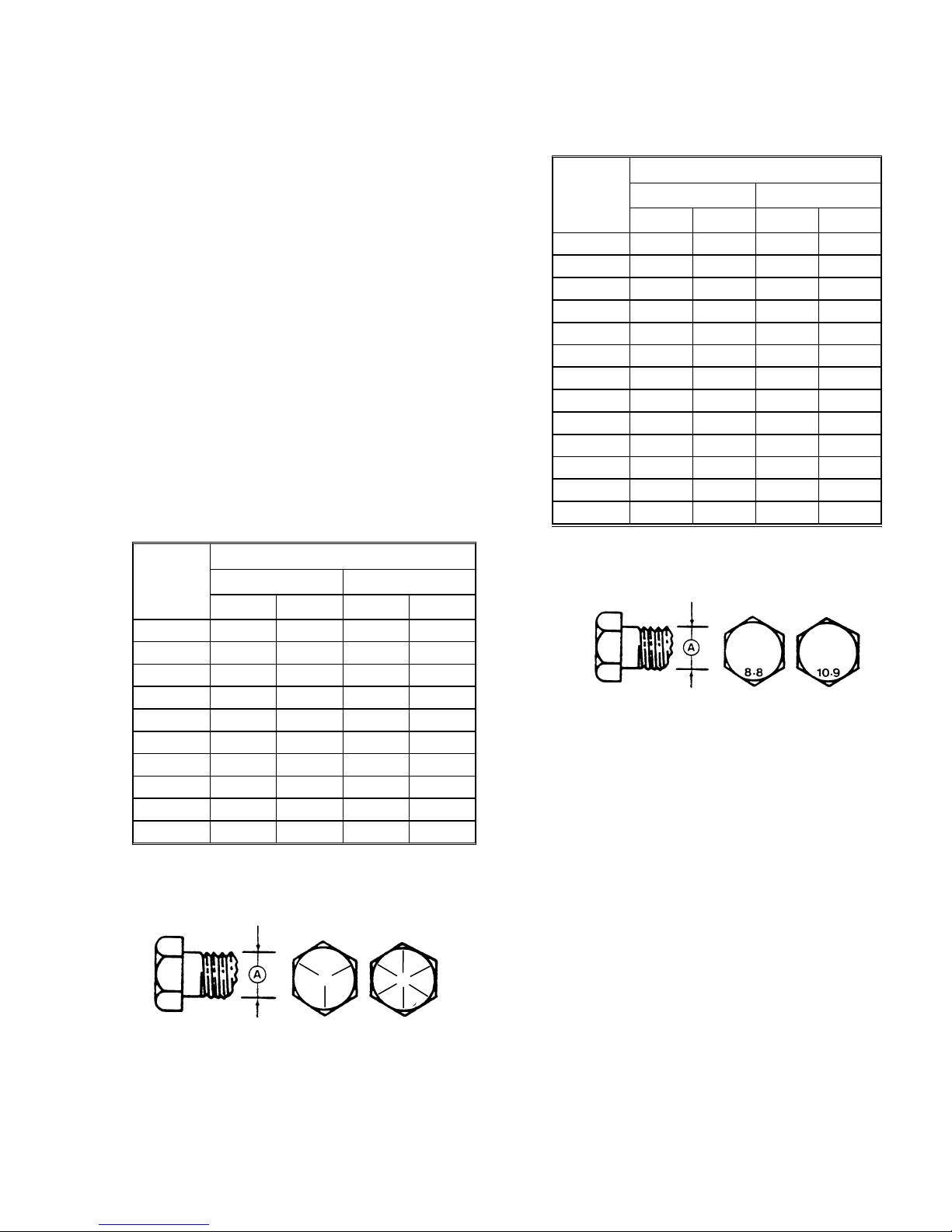
B. SAE BOLTS
NC BOLT TORQUE*
BOLT
DIA. "A"
in.
1/4 9 12 11 15
5/16 18 24 25
3/8 32 43 41
7/16 50 68 70 95
1/2 75 102 105 142
9/16 110 149 149 202
5/8 150 203 200 271
3/4
7/8 420 569 600 813
1 640 867 890 1205
* Torque categories for bolts and capscrews are identified by their
head markings.
SAE 5 SAE 8
ft·lbf N·m ft·lbf N·m
34
56
265 359
365 495
C. METRIC BOLTS
NC BOLT TORQUE*
BOLT
DIA. "A"
M3 0.4 0.5 1.3 1.8
M4 2.2 3 3.3 4.5
M5 4 6 7 9
M6 7 10 11 15
M8 18 25 26 35
M10 37 50 52 70
M12 66 90 92 125
M14 103 140 148 200
M16 166 225 229 310
M20 321 435 450 610
M24 553 750 774 1050
M30 1103 1495 1550 2100
M36 1917 2600 2710 3675
* Torque categories for bolts and capscrews are identified by their
head markings.
8.8 10.9
ft·lbf N·m ft·lbf N·m
SAE-5 SAE-8
Form 169242 Revision D
5
Page 8
D. FLARE TYPE HYDRAULIC FITTINGS
FLARE
FLARESEAT
a. Check flare and flare seat for defects that might
cause leakage.
b. Align tube with fitting before tightening.
c. Lubricate connection and hand tighten swivel nut
until snug.
d. To prevent twisting the tube(s), use two wrenches.
Place one wrench on the connector body and with
the second, tighten the swivel nut to the torque
shown.
TUBE
SIZE
SAE
O.D.
NO.
(in.)
3 3/16
4 1/4
5 5/16
6 3/8
8 1/2
10 5/8
12 3/4
14 7/8
16 1
* The torque values shown are based on lubricated connections
as in reassembly.
THD
SIZE
(in.)
3/8
7/16
1/2
9/16
3/4
7/8
1-1/16
1-3/8
1-5/16
NUT
SIZE
ACROSS
FLATS
(in.)
7/16 6 8 1 1/6
9/16 9 12 1 1/6
5/8 12 16 1 1/6
11/16 18 24 1 1/6
7/8 34 46 1 1/6
1 46 62 1 1/6
1-1/4 75 102 3/4 1/8
1-3/8 90 122 3/4 1/8
1-1/2 105 142 3/4 1/8
NUT
BODY
RECOMMENDED
TORQUE
VALUE*
ft·lbf N·m Flats Turns
TURNS TO
TIGHTEN
(AFTER FINGER
TIGHTENING)
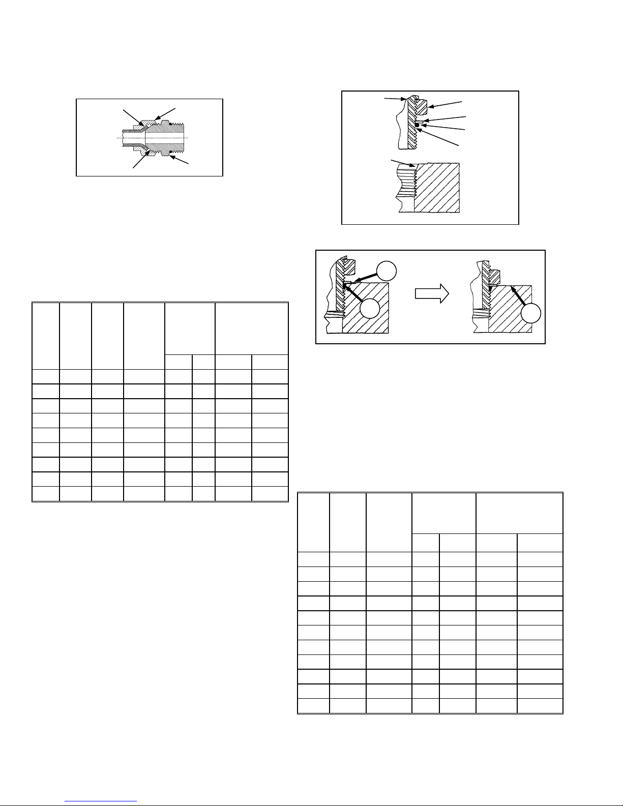
E. O-RING TYPE HYDRAULIC FITTINGS
FITTING
SEAT
a. Inspect O-ring and seat for dirt or obvious defects.
A
B
b. On angle fittings, back off the lock nut until washer
(A) bottoms out at top of groove (B) in fitting.
c. Hand tighten fitting until back up washer (A) or
washer face (if straight fitting) bottoms on part
face (C) and O-ring is seated.
d. Position angle fittings by unscrewing no more than
one turn.
e. Tighten straight fittings to torque shown.
f. Tighten angle fittings to torque shown in the
following table while holding body of fitting with a
wrench.
TORQUE
VALUE*
ft·lbf N·m Flats Turns
SAE
NO.
THD
SIZE
(in.)
NUT SIZE
ACROSS
FLATS
(in.)
LOCKNUT
WASHER
O-RING
GROOVE
C
RECOMMENDED
TURNS TO TIGHTEN
(AFTER FINGER
TIGHTENING)
Form 169242 Revision D
3 3/8 1/2 6 8 2 1/3
4 7/16 9/16 9 12 2 1/3
5 1/2 5/8 12 16 2 1/3
6 9/16 11/16 18 24 2 1/3
8 3/4 7/8 34 46 2 1/3
10 7/8 1 46 62 1-1/2 1/4
12 1-1/16 1-1/4 75 102 1 1/6
14 1-3/16 1-3/8 90 122 1 1/6
16 1-5/16 1-1/2 105 142 3/4 1/8
20 1-5/8 1-7/8 140 190 3/4 1/8
24 1-7/8 2-1/8 160 217 1/2 1/12
* The torque values shown are based on lubricated connections
as in reassembly.
6
Page 9

ENGLISH/METRIC EQUIVALENTS
QUANTITY
FACTOR
UNIT NAME ABBR. UNIT NAME ABBR.
Area acres acres x 0.4047 = hectares ha
Flow US gallons per minute (gpm) x 3.7854 = liters per minute L/min
Force pounds force lbf x 4.4482 = Newtons N
INCH-POUND UNITS
Length
Power horsepower hp x 0.7457 = kilo watts kW
Pressure pounds per square inch psi
Torque
Temperature degrees Fahrenheit ˚F (˚F - 32) x 0.56 = Celsius ˚C
Velocity
Volume
Weight pounds lb x 0.4536 = kilograms kg
inch in. x 25.4 = millimeters mm
foot ft x 0.305 = meters m
x 6.8948 = kilopascals kPa
x .00689 = megapascals MPa
pound feet or foot pounds lbf·ft or ft·lbf x 1.3558 = newton meters N·m
pound inches or inch pounds lbf·in. or in·lbf x 0.1129 = newton meters N·m
feet per minute ft/min x 0.3048 = meters per minute m/min
feet per second ft/s x 0.3048 = meters per second m/s
miles per hour mph x 1.6063 = kilometers per hour km/h
US gallons US gal. x 3.7854 = liters L
ounces oz. x 29.5735 = milliliters ml
cubic inches in.3 x 16.3871 = cubic centimeters cm3 or cc
SI UNITS (METRIC)
DEFINITIONS
TERM DEFINITION
API
ASTM
Cab-Forward
CDM
DWA
Engine-Forward
ISC
N-DETENT
rpm
SAE
WCM
Windrower
Windrower Tractor
Form 169242 Revision D
American Petroleum Institute
American Society of Testing And Materials
Windrower operation with the Operator and cab facing in the direction of travel.
Cab Display Module
Double Windrow Attachment
Windrower operation with the Operator and engine facing in the direction of travel.
Integrated Speed Control
The slot opposite the neutral position on Operator’s console.
revolutions per minute
Society Of Automotive Engineers
Windrower Control Module
Windrower with header attached.
Power unit only. (Windrower without the header attached)
7
Page 10
UNLOADING AND ASSEMBLY
STEP 1. UNLOAD CONTAINER
CAUTION
To avoid injury to bystanders from being
struck by machinery, do not allow persons to
stand in unloading area.
a. Move trailer into position and block trailer wheels.
b. Lower trailer storage stands.
c. Open container doors and remove all blocking.
d. Check container floor for nails or other
obstructions and remove if necessary.
e. Position platform or ramp at container opening.
STEP 2. MOVE TO ASSEMBLY
AREA
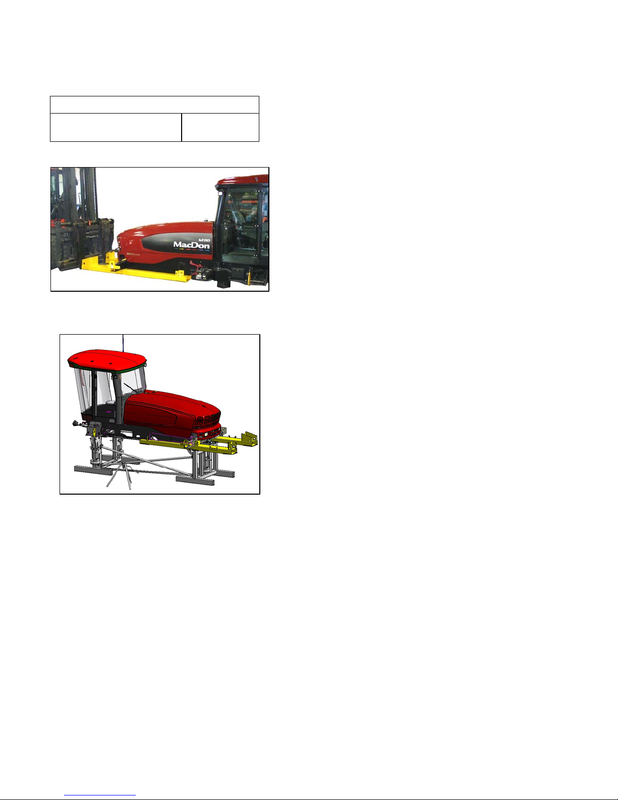
A. CRANE METHOD
CAUTION
To avoid injury to bystanders from being
struck by machinery, do not allow persons to
stand in unloading area.
CAUTION
Equipment used for unloading must meet or
exceed the requirements specified below.
Using inadequate equipment may result in
chain breakage, vehicle tipping or machine
damage.
LIFTING VEHICLE
Minimum Lifting Capacity 20,000 lb (9072 kg)
CHAIN
Type
Overhead Lifting
Quality (1/2 inch)
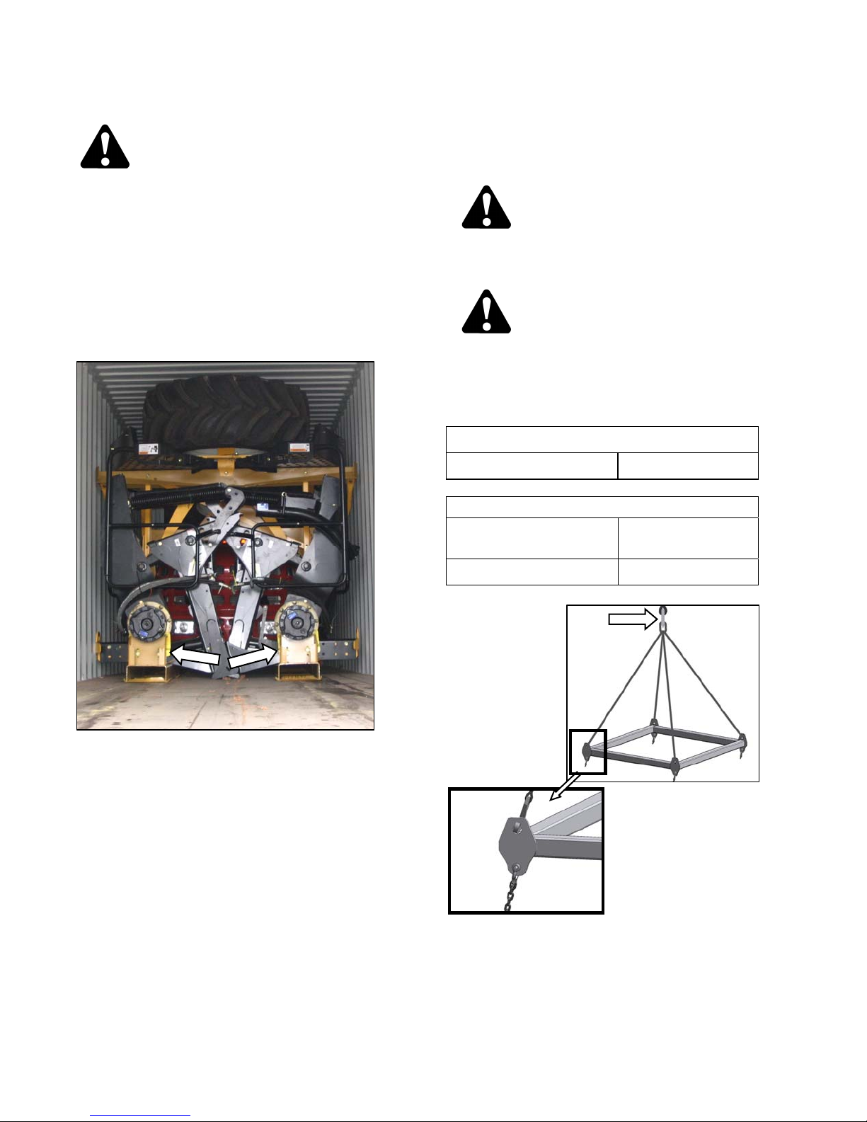
f. Attach chain/pull strap to slots in support channels
as shown.
g. Pull windrower from container onto platform.
Minimum Working Load 7100 lb (3221 kg)
a. Attach chains or cable to the four lift points on the
lifting frame (MacDon Part # 163871) and connect
loop ends to crane hook. Use cable or chain with
a minimum lifting capacity of 7100 lb (3221 kg).
(continued next page)
Form 169242 Revision D
8
Page 11
UNLOADING AND ASSEMBLY
B. FORKLIFT METHOD
To avoid injury to bystanders from being
struck by machinery, do not allow persons to
stand in unloading area.
Equipment used for unloading must meet or
exceed the requirements specified below.
Using inadequate equipment may result in
chain breakage, vehicle tipping or machine
damage.
Minimum Lifting Capacity * 20,000 lb (9072 kg)
CAUTION
CAUTION
LIFTING VEHICLE
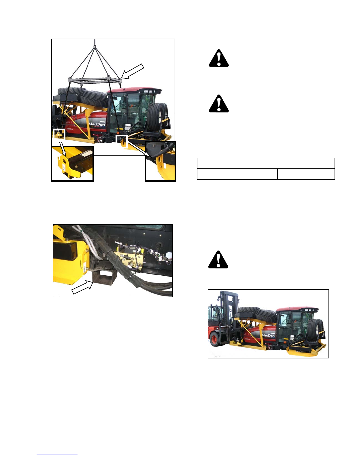
b. Attach lifting frame assembly (MacDon Part #
163871) to the four designated lift points on
windrower shipping frame.
c. Lift windrower off platform, and move to setup
area.
d. Lower assembly onto 5 - 6 inch (127 - 152 mm)
blocks as shown.
e. Remove chains from shipping frame.
f. Check for shipping damage and missing parts.
* At 48 inches (1220 mm) from back end of forks.
IMPORTANT
Forklifts are normally rated for a load
located 24 inches (610 mm) ahead of
back end of the forks.
To obtain the forklift capacity at 48
inches (1220 mm), check with your
forklift distributor.
WARNING
Be sure forks are secure before moving away
from load. Stand clear when lifting.
Form 169242 Revision D
a. Approach windrower from the hood end, and slide
forks underneath lifting framework.
b. Raise windrower off platform, and move to
assembly area.
(continued next page)
9
Page 12
UNLOADING AND ASSEMBLY
c. Lower assembly onto 5 - 6 inch (127 - 152 mm)
blocks as shown.
d. Check for shipping damage and missing parts.
Form 169242 Revision D
10
Page 13
UNLOADING AND ASSEMBLY
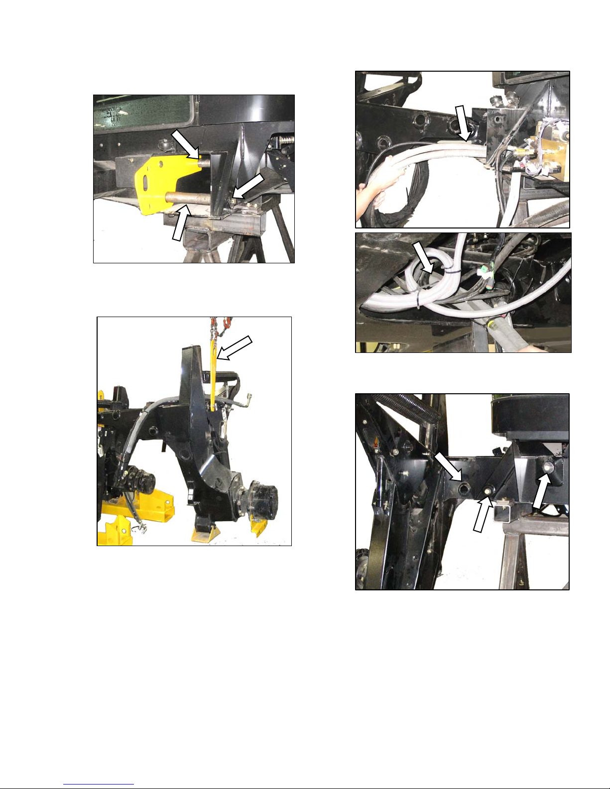
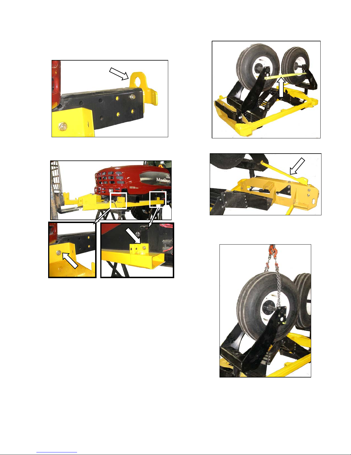
STEP 3. REMOVE WHEEL AND
STEP ASSEMBLY
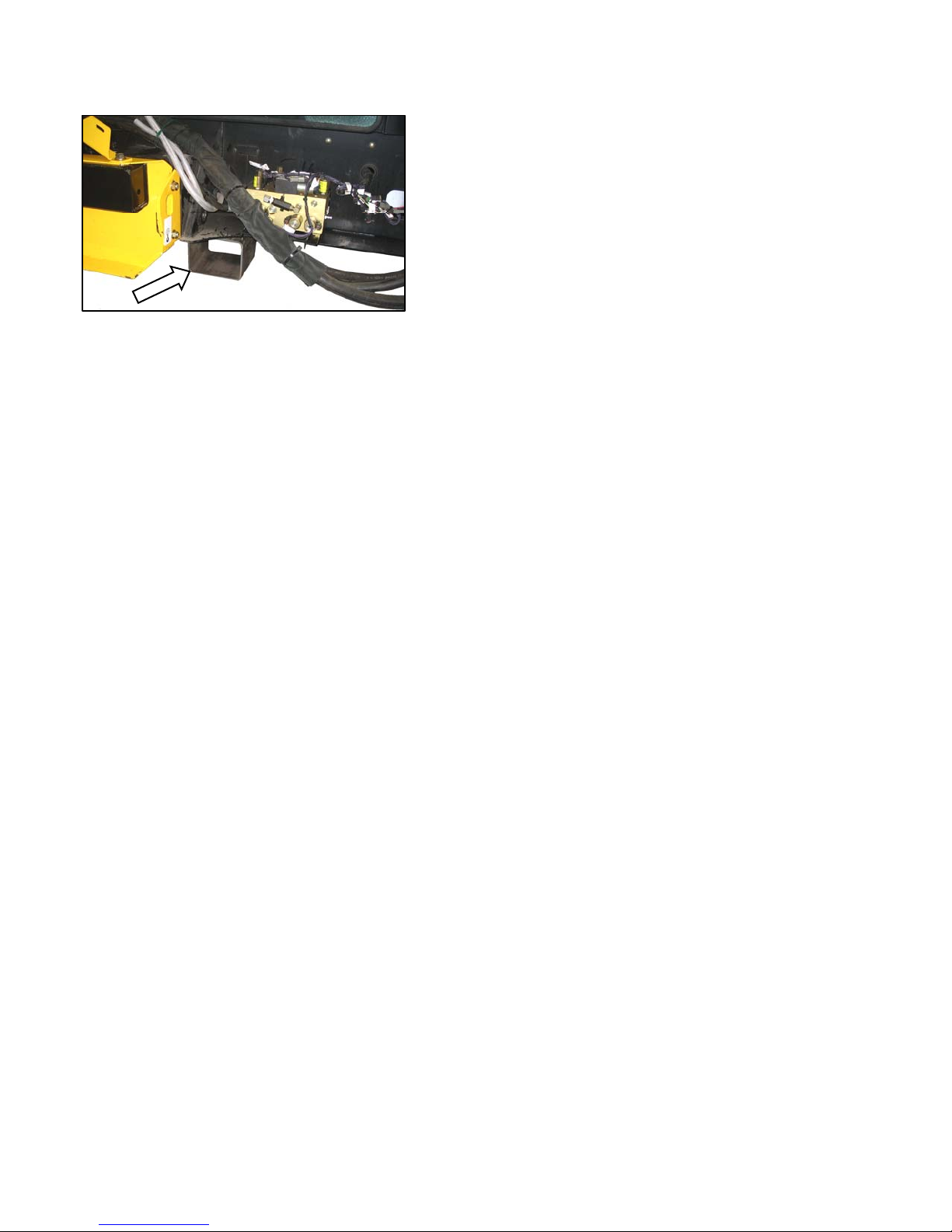
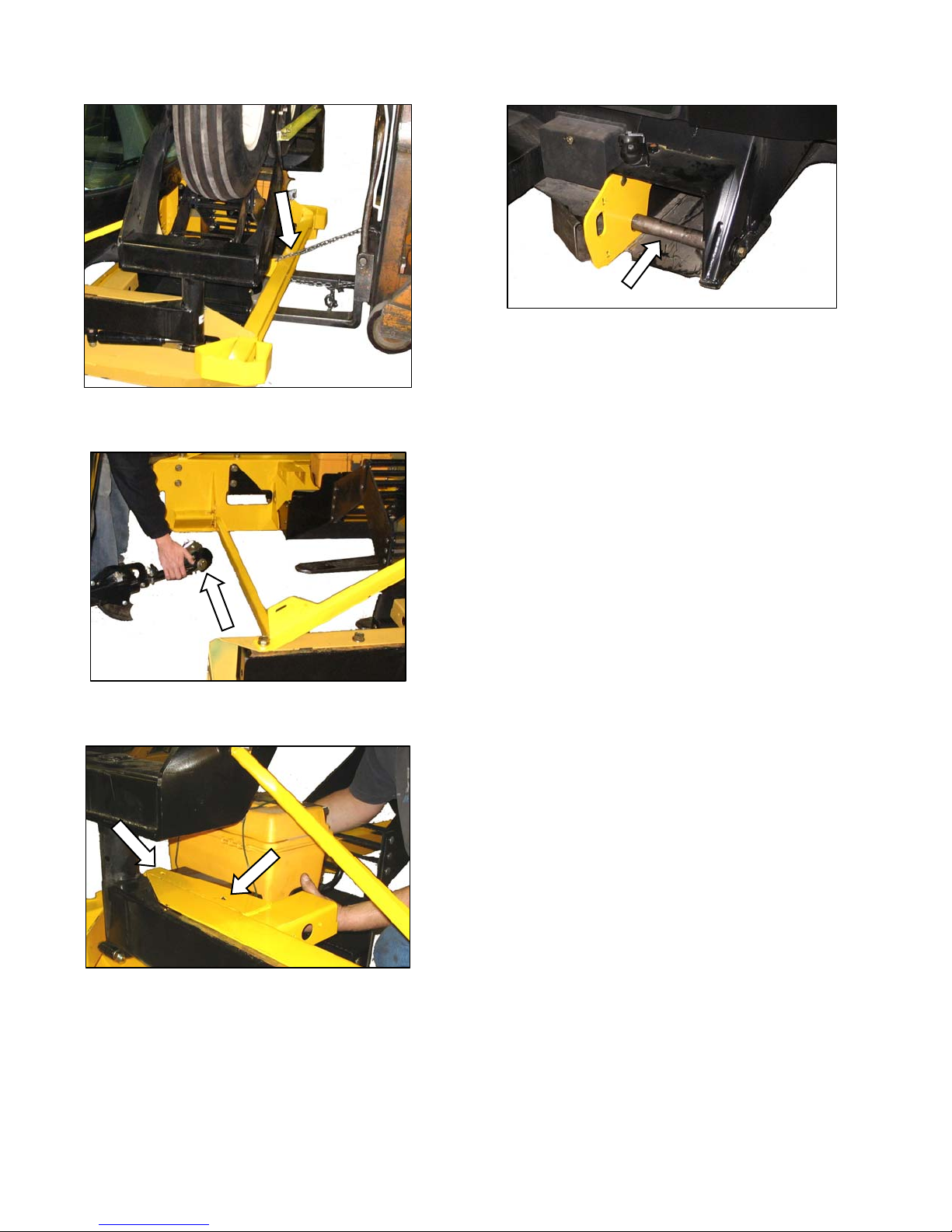
a. Remove shipping wire and bolt securing hose
support to shipping frame, and remove hose
support.
b. Lay hose support off to the side.
e. Remove the four (two per side) carriage bolts at
the rear of the wheel/step assembly.
c. Remove the two ¾ in. x 16.5 long bolts (one per
side) at front frame beam. Retain for
reinstallation.
f. Remove plastic cable tie and shipping wire
d. Remove the 1 inch (25.4 mm) pin at the center-
link.
Form 169242 Revision D
11
securing hose bundles to frame.
(continued next page)
Page 14
UNLOADING AND ASSEMBLY
g. Attach a chain to wheel/step assembly, and pull
away from shipping assembly with lifting device.
j. Reinstall leg bolts, washers, and nuts to secure
the lifting plate onto the mainframe.
h. Lift center-link so that it clears wheel/step
assembly frame.
i. Remove bolts, and remove tool box and holder
from shipping frame. Loosely install bolts in
holder, and set aside for later installation.
Form 169242 Revision D
12
Page 15
UNLOADING AND ASSEMBLY
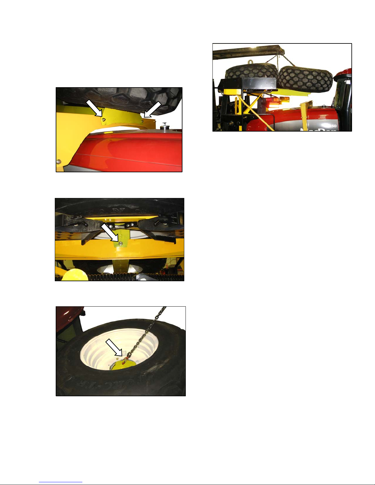
STEP 4. REMOVE DRIVE WHEELS
IMPORTANT
Remove the drive wheels as a pair from
above the hood.
a. Remove the two bolts at front cross member over
the hood.
d. Carefully lift wheels off frame.
IMPORTANT
Ensure that tire is guided away from
cab roof when lifting wheels to prevent
damage to the cab. Chain on forward
wheel should be snug and loose on the
aft wheel.
e. Set wheels aside for later installation.
b. Remove one bolt at rear of hood directly under
center of drive wheel.
c. Attach a lifting device to lift hooks located in the
center of each drive wheel.
Form 169242 Revision D
13
Page 16
UNLOADING AND ASSEMBLY
STEP 5. REMOVE PLATFORM /
LIGHT ASSEMBLY
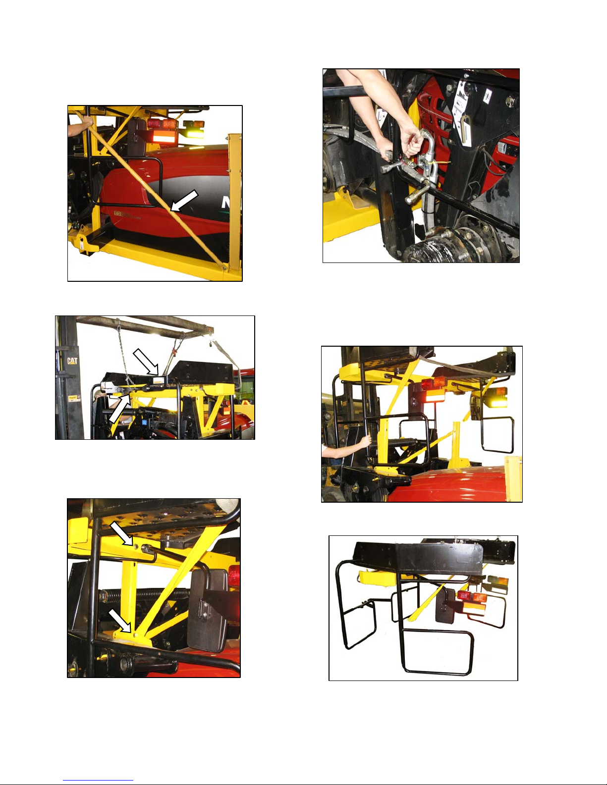
a. Remove the two support tubes on either side of
hood.
d. Cut plastic cable ties, and move hose bundle clear
of platform.
NOTE
The M100 windrower is equipped with
only one platform.
b. To prevent paint damage, attach slings to platform
at locations shown, and to a lifting device with a
minimum lifting capacity of 5000 lb (2268 kg), and
a lift height of 13 feet (4 m).
e. Carefully lift platform/light assembly off frame until
rails clear windrower legs.
c. Remove two 5/8 in. x 5.0 bolts at top of vertical
support, and two bolts on bottom of support brace.
Form 169242 Revision D
f. Back away from windrower, and set assembly on
a level surface. Protect handrails with foam or
cardboard to prevent paint damage.
14
Page 17
UNLOADING AND ASSEMBLY
STEP 6. INSTALL LIGHT AND
MIRROR ASSEMBLIES
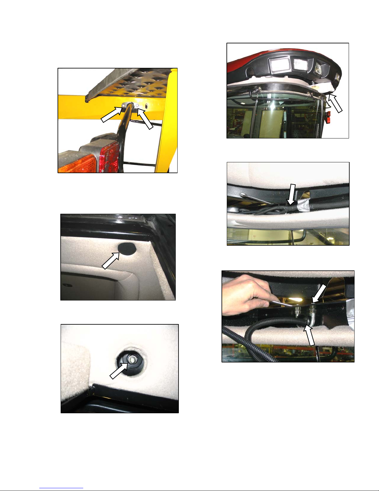
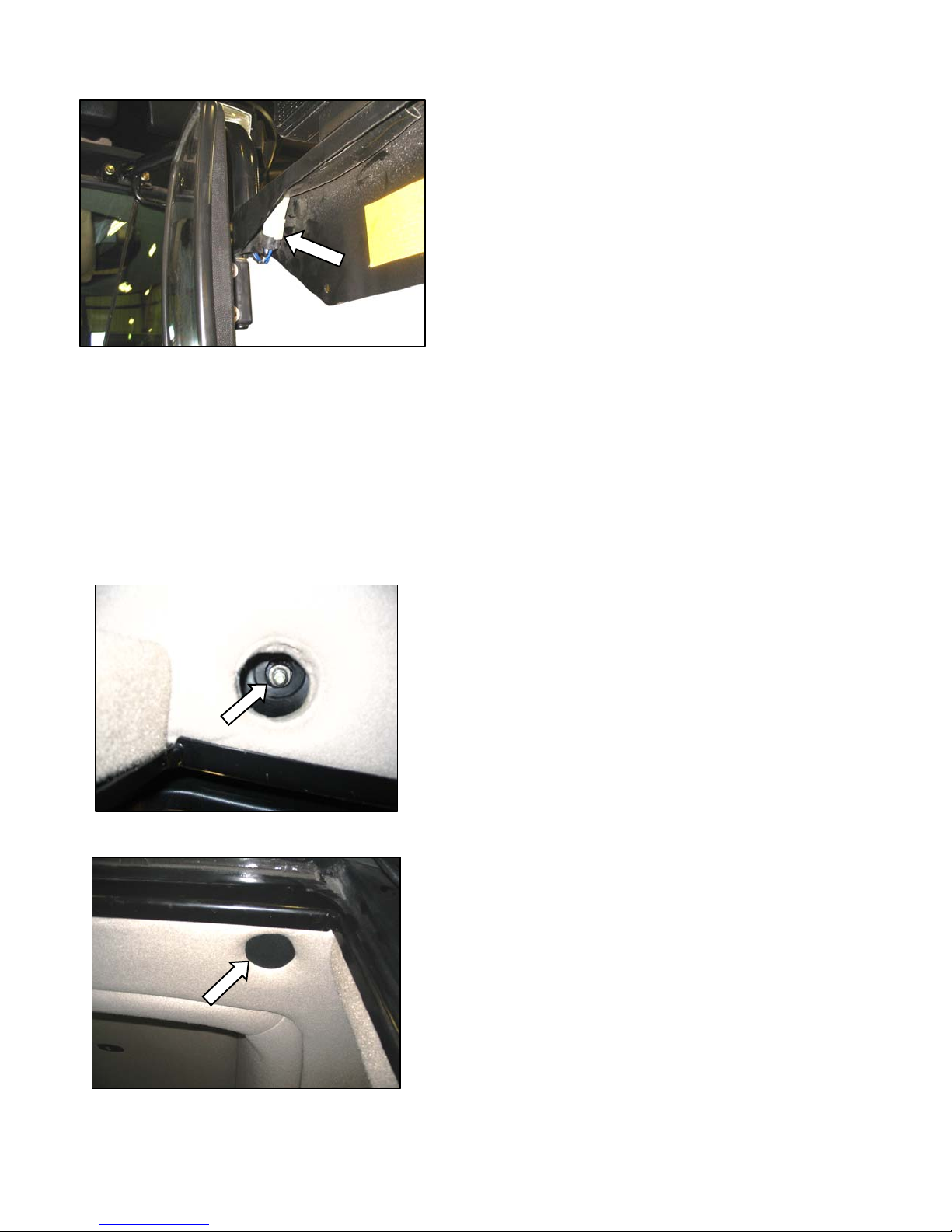
a. Remove two bolts securing mirror/light assemblies
to shipping stand, and remove assemblies.
b. The cab roof must be raised to install the light
assemblies. Proceed as follows:
3. Lift roof, and support with wooden block
covered with foam to prevent scuffing of roof.
c. Move existing harness in roof to gain access to
1. Remove plastic covers from six bolt locations
in roof.
2. Remove nuts and washers at these locations.
mirror/light support clamps. Loosen U-bolt.
d. Install mirror / light into U-bolt, and tighten nuts on
U-bolt so that support tube is securely fastened.
Tighten jam-nuts located under roof plate.
(continued next page)
Form 169242 Revision D
15
Page 18
UNLOADING AND ASSEMBLY
e. Thread wiring harness through support tube so
that connector is visible at light assembly.
f. Stuff foam into end of tube to help prevent dust
and noise from entering the cab.
g. Connect harness to connector at light.
h. Repeat steps c. to g. for opposite light assembly.
i. Remove roof support and lower ro of.
IMPORTANT
Ensure roof bolts clear grommets in
frame.
j. Reinstall washers and nuts at the six locations.
k. Reinstall plastic caps.
Form 169242 Revision D
16
Page 19
UNLOADING AND ASSEMBLY
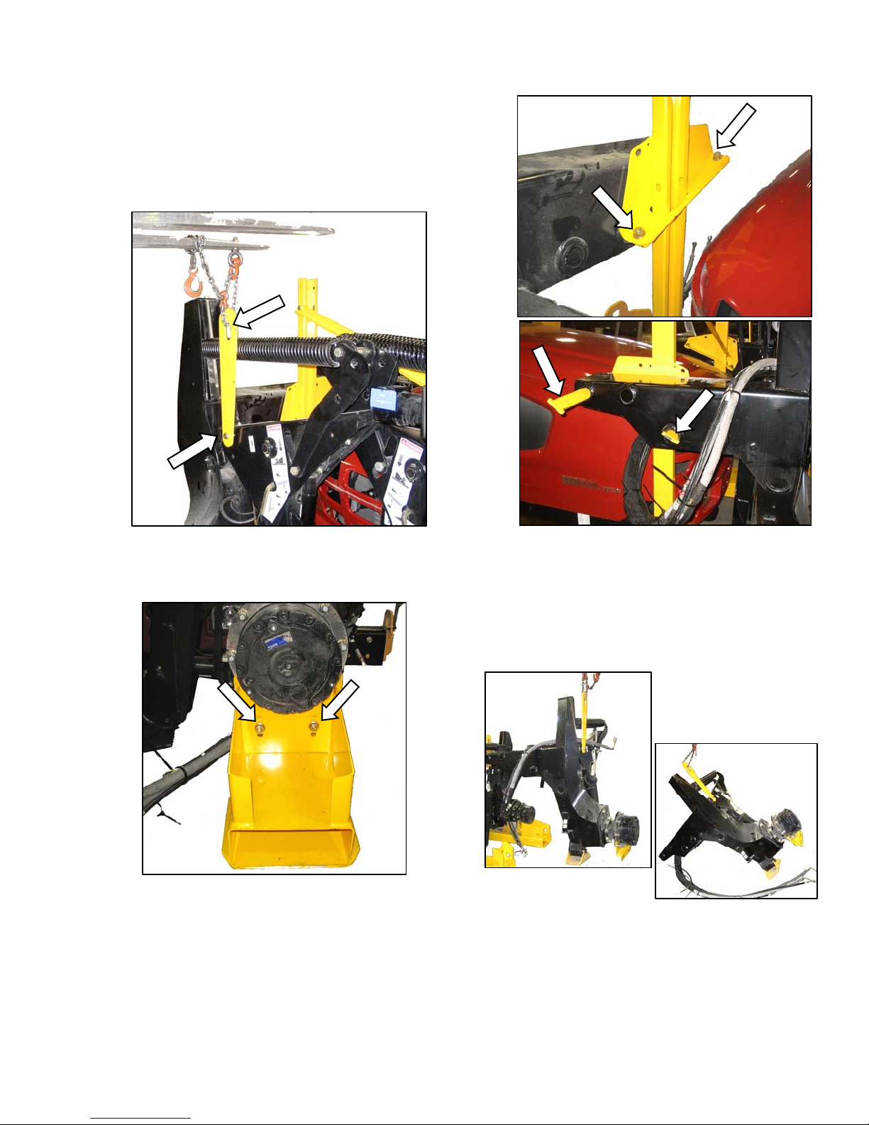
STEP 7. REMOVE LEG
ASSEMBLIES
a. Ensure that lift bar is attached to leg assembly as
shown, and that clevis pin is installed with head on
near side.
b. Attach chain to lifting bar on leg assembly, and
hook up to lifting device with a minimum lifting
capacity of 5000 lb (2268 kg).
c. Remove two bolts at lower support channel.
d. Remove two bolts near top of leg, and remove
bars from leg.
NOTE
Insert cardboard or foam between leg
assembly and hood to prevent damage
to hood.
e. Lift off leg assembly, and set securely on level
ground.
f. Repeat above steps for second leg assembly.
Form 169242 Revision D
17
Page 20
UNLOADING AND ASSEMBLY
STEP 8. REMOVE WHEEL AND
PLATFORM SUPPORT
a. Remove cross brace, and the two upright supports
from frame.
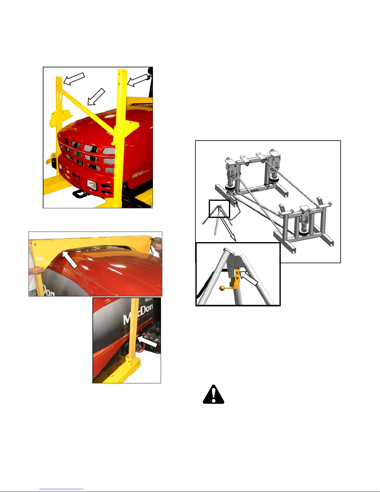
STEP 9. ASSEMBLE WINDROWER
SUPPORT STAND
Special stands for assembling the wi ndrow er are
available from the factory. If this stand is not
available, an equivalent support system can be
used.
The stand must be capable of holding a 20,000 lb
(9072 kg) load.
Assemble factory stand as follows:
a. Remove all shipping materials from stand.
FORWARD STAND
SUPPORT
b. Remove the cross member over the hood, and the
two uprights on either side.
REAR STAND
b. Arrange forward and rear stands on level ground,
so that attachment lugs on each stand face each
other.
c. Attach four support tubes to stands as shown wit h
hardware provided, and tighten.
d. Set up air control valve tripod. Remove plug on
valve, and install a 100 psi (689 kPa) air line.
e. The stand is now operational. Instructions for use
are given in the appropriate sections.
WARNING
• Use stand only as instructed in this
manual. Do not use stand for any other
purpose.
Form 169242 Revision D
• Do not pressurize air bags beyond 120 psi
(827 kPa).
18
Page 21
UNLOADING AND ASSEMBLY
STEP 10. LIFT WINDROWER ONTO
STAND
CAUTION
To avoid injury to bystanders from being
struck by machinery, do not allow persons to
stand in unloading area.
CAUTION
Equipment used for unloading must meet or
exceed the requirements specified below.
Using inadequate equipment may result in
chain breakage, vehicle tipping or machine
damage.
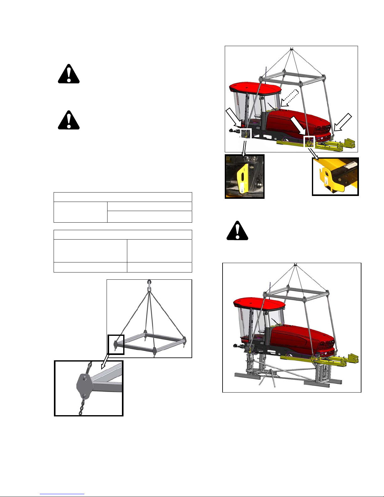
A. CRANE METHOD
LIFTING VEHICLE
Crane
Minimum Lifting Capacity
20000 lb (9072 kg)
CHAIN
b. Attach the lifting frame to the four designated lift
points on windrower shipping frame as shown.
CAUTION
Type
Minimum Working Load
a. Attach four chains or cables to the four lift points
on the lifting frame (MacDon Part # 163871), and
connect loop ends to crane hook. Use cable or
chain with a minimum lifting capacity of 7100 lb
(3221 kg).
Overhead Lifting
Quality (1/2 inch)
7100 lb (3221 kg)
Stand clear when lifting, as machine may
swing.
c. Lift windrower onto stand.
d. Remove chains from shipping frame, and set
lifting frame assembly clear of work area.
Form 169242 Revision D
19
Page 22
UNLOADING AND ASSEMBLY
B. FORKLIFT METHOD
LIFTING VEHICLE
Minimum Lifting Capacity *
* At 48 inches (1220 mm) from back end of forks.
a. Approach windrower from aft end, and slide forks
fully into shipping support channels.
20,000 lb
(9072 kg)
b. Raise windrower and place onto stand.
c. Back away forklift.
Form 169242 Revision D
20
Page 23
UNLOADING AND ASSEMBLY
STEP 11. INSTALL LEGS
a. Remove front leg bolts and pins, and set aside for
reinstallation. Remove carriage bolt, and remove
lifting plate.
b. Attach front leg to lifting device with lifting bar.
c. Position leg at frame.
d. Feed hydraulic hose bundle into frame, and
through hole at center of frame.
e. Insert leg into frame, and line up holes in frame
and leg at the first position (widest tread with one
exposed hole).
f. Insert pins and secure with ¾ in. x 16.5 long bolts,
washers, and nuts. Torque to 100 ft·lbf (136 N·m).
g. Repeat above steps for other leg.
(continued next page)
Form 169242 Revision D
21
Page 24

UNLOADING AND ASSEMBLY
h. Slightly lift th e header lift arms with lifting device,
and remove lifting bars from legs. Relocat e spring
locking pins to front of lift arms.
Form 169242 Revision D
22
Page 25
UNLOADING AND ASSEMBLY
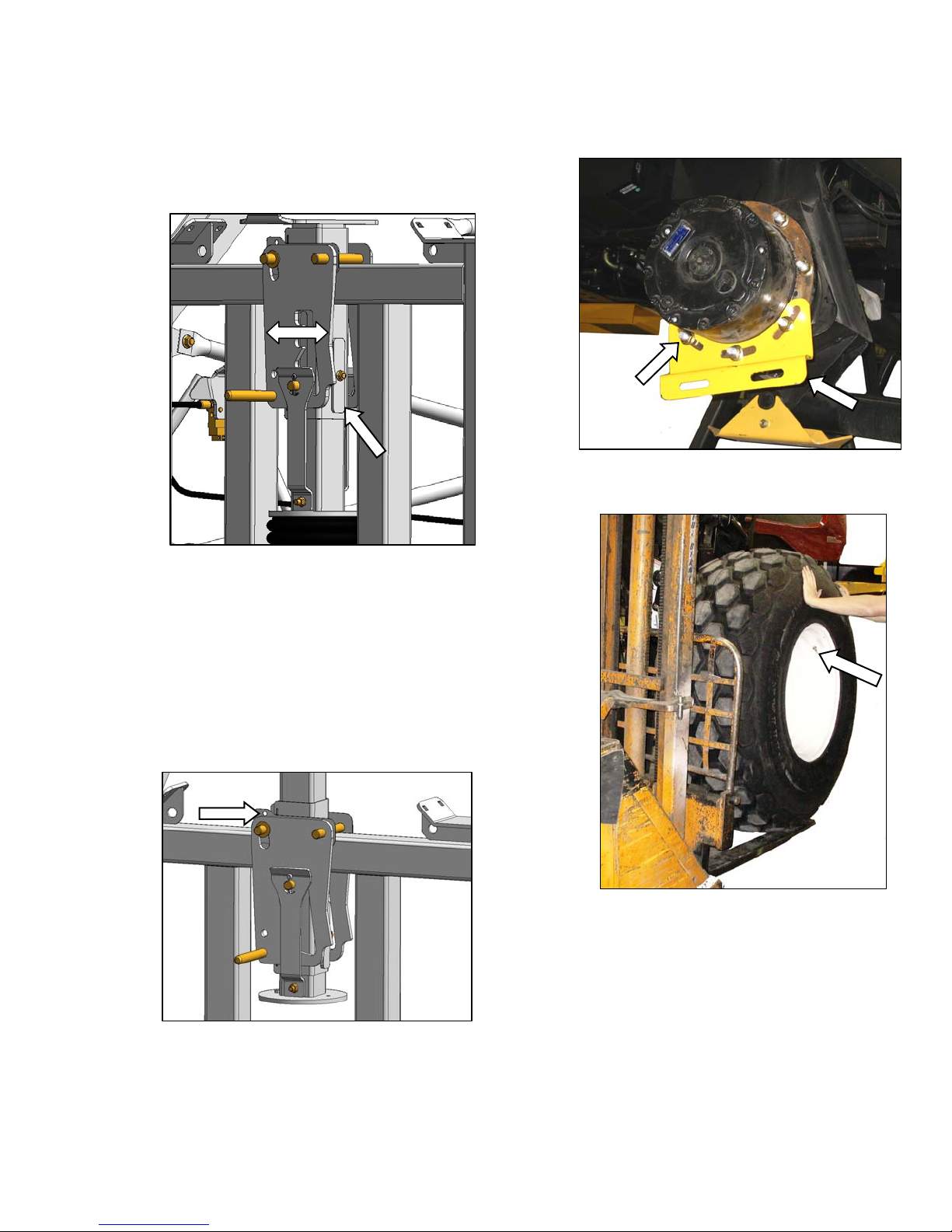
STEP 12. INSTALL FRONT
WHEELS
a. If factory stand is being used, proceed as follows,
otherwise proceed to step b:
4. Release pressure so that locks support we ight
of windrower.
b. Remove shipping supports on drive wheel hubs,
and remove wheel lug nuts.
1. Ensure that the three (one at rear, two at
front) lift locks are activated on lift mechanism.
NOTE
Lock is activated when keeper is
vertical, and latch is free to move back
and forth.
2. Pressurize air bag system (100 psi (689 kPa)
air pressure required), and raise windrower to
maximum height [approximately 7 inches (178
mm)] above stand.
3. Verify that all three locks are engaged, before
to proceeding to next step.
NOTE
c. Position wheel against hub so that that air valves
are on outside, and tire tread points forward.
For "Turf” tires (diamond tread), be sure arrow on
sidewall points in forward rotation.
d. Lift wheel on hub with lifting device. Lower lifting
device.
e. Rotate wheel to align holes with studs, and push
wheel onto studs.
(continued next page)
Lock is engaged when witness hole
above pin is exposed.
Form 169242 Revision D
23
Page 26
UNLOADING AND ASSEMBLY
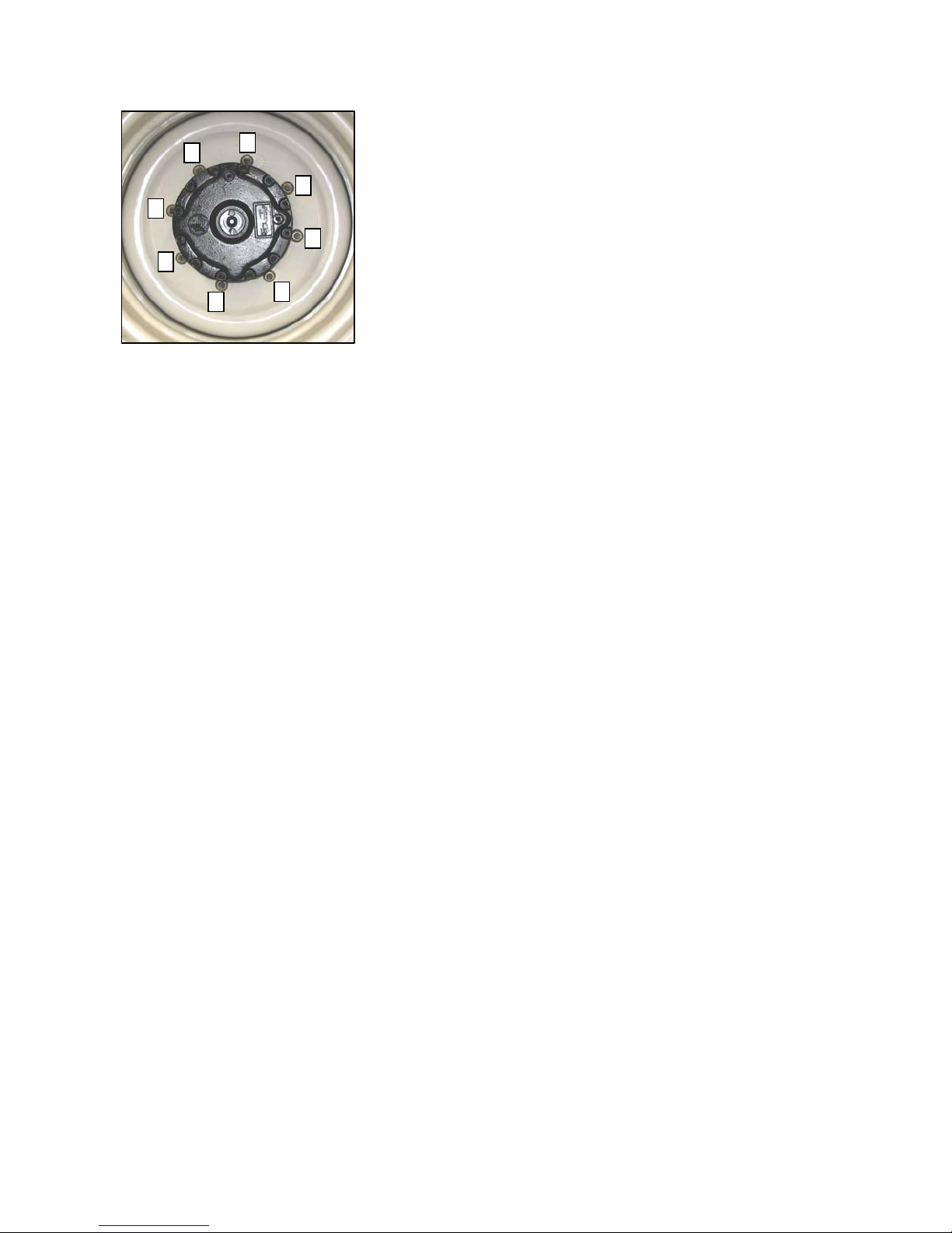
6
1
4
3
7
8
5
2
f. Install wheel nuts, and tighten to 220 ft·lbf (300
N·m) using the tightening sequence as shown.
NOTE
To avoid damage to wheel disks, do not
over-tighten wheel nuts.
g. Repeat sequence three times.
Form 169242 Revision D
24
Page 27
UNLOADING AND ASSEMBLY
STEP 13. INSTALL CASTER
WHEELS
a. Remove the two guide plates from ends of walking
beam.
b. Support shipping frame channel, and remove bolts
attaching shipping frame to walking beam and
mainframe side rail. Remove shipping frame.
NOTE
d. Remove tie bar between the two caster wheels.
e. Remove the two braces from caster wheels and
frame. Retain bolts for attaching caster to walking
beam.
Shipping frame does not need to be
removed if air bag lifting stand is used.
Ensure bolts are removed prior to
moving windrower off stand.
c. Repeat above for opposite shipping frame
channel.
Form 169242 Revision D
f. Attach a chain to RH caster, and support caster
with lifting device.
(continued next page)
25
Page 28

UNLOADING AND ASSEMBLY
g. Remove five remaining bolts securing caster to
shipping frame. Retain bolts for attaching caster
to walking beam.
CAUTION
Stand clear when lifting, as caster may
swing.
k. Tighten bolts as follows:
1. Snug up the two bolts underneath beam.
2. Tighten the four back bolts to 330 ft·lbf (447
N·m).
3. Tighten bolts underneath beam to 330 ft·lbf
(447 N·m).
l. Repeat above steps g. to k. for LH ca ster.
m. Re-torque bolts at 5, and 10 hours of operation.
h. Lift caster assembly off shipping frame, and
position at end of walking beam.
i. Insert RH caster extension into walking beam, and
position for desired tread.
j. Install six ¾ in. bolts and hardened washers into
walking beam and caster beam. Use longer bolts
through anti-shimmy bracket.
Form 169242 Revision D
26
Page 29
UNLOADING AND ASSEMBLY
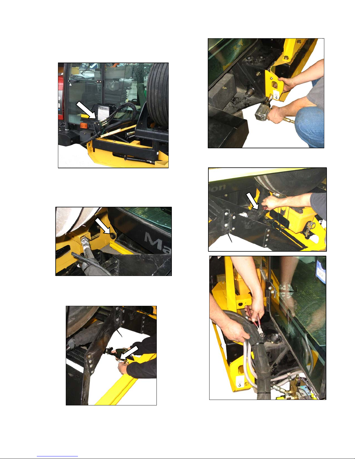
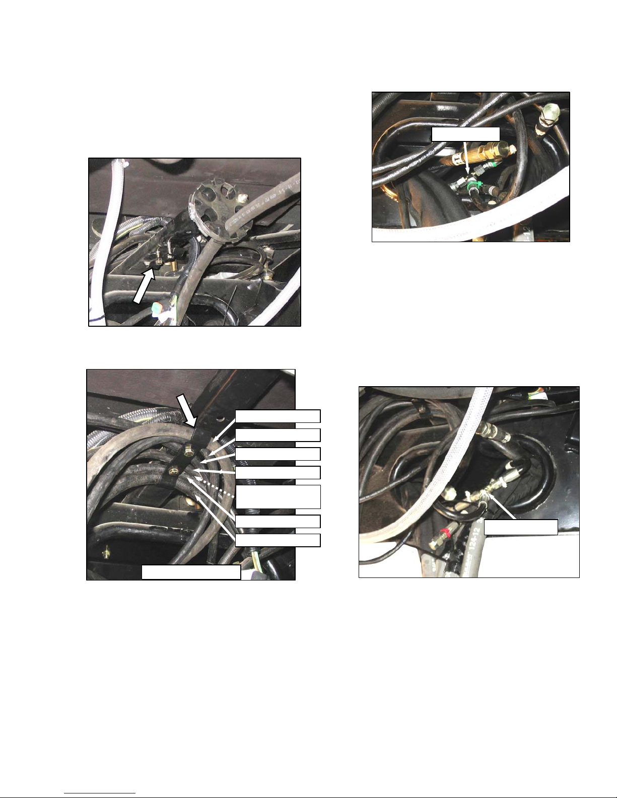
STEP 14. INSTALL HYDRAULICS
A. M150, M200
a. The hydraulic hoses under the cab may require
proper placement under the existing clip. If
necessary, proceed as follows:
b. Connect hoses as follows, using coloured plastic
cable ties as a guide.
111327 GREEN
1. Locate two hoses 111327 (green ties) in
frame opening, and existing tee fitting (green
tie).
2. Remove caps on green lines and tee, and
make connections. Tighten fittings.
NOTE
1. Locate hose clip under the cab, and remove
clip.
111557 YELLOW
111323 BLUE
111323 ORANGE
111324 WHITE ‘T’
111324 (M200 ONLY)
(NOT SHOWN)
111327 GREEN ‘T’
111328 WHITE
VIEW FORWARD
2. Position hose 111323 (orange tie) and hose
111324 with tee (white tie), as shown under
the center of the clip, and loosely install two
bolts and nuts. Part numbers are located on
hoses. (If M200, place another hose 1132A
with tee under clip)
3. Position remaining hoses under clip as shown,
and tighten bolts.
Remove caps on tee last to minimize oil
loss.
3. Position hoses into frame.
111324 WHITE ‘T’
4. Locate two hoses (white ties) inside frame,
and hose 111324 with tee (white tie).
5. Remove caps, make connections, and tighten
fittings.
6. Push hoses into frame.
(continued next page)
Form 169242 Revision D
27
Page 30

RED
UNLOADING AND ASSEMBLY
ORANGE
BLUE
YELLOW
7. Locate two hoses (red ties) inside frame.
8. Route RH hose behind bundle.
9. R emove ca ps, make conn ection , and tighten
fitting.
10. Push hose into frame.
119328 WHITE
11. Retrieve long hose 119328 (white tie), and
route through hole in LH frame.
13. Remove the caps from three fittings (blue,
orange, and yellow ties) on the valve block
from inboard side of frame.
14. Loosen bolts, and move valve block to
improve access through hole in frame for
wrenches when tightening fittings.
WHITE
12. Remove caps on hose, and valve block fitting
(white tie), and make connection. Tighten
fitting.
Form 169242 Revision D
BLUE
ORANGE
YELLOW
15. Retrieve matching hoses and make
connections on valve block. Tighten fittings.
16. Reposition valve block and re-tighten bolts.
(continued next page)
28
Page 31

UNLOADING AND ASSEMBLY
c. Remove clamp from round plastic hose block.
TRACTION DRIVE - LH
e. Connect drive hoses to pump as follows:
SHORT - NO TIE
SHORT - YELLOW
1. Remove caps, and attach hoses with short
elbows to respective side of pump (either
yellow or no tie). Tighten fittings.
LONG - RED
CASE DRAIN TRACTION DRIVE - RH
VIEW LOOKING AFT TOWARDS PUMPS
d. Insert four traction drive hoses and one case drain
hose into slots in block as shown, and reinstall
clamp.
LONG - NO TIE
2. Remove caps, and attach hoses with long
elbows to respective side of pump (either red
or no tie). Tighten fittings.
f. Retrieve the two motor case drain hoses (111312)
at front frame, and the 7/8 in. tee fitting on the
hose, from the pump.
(continued next page)
Form 169242 Revision D
29
Page 32

UNLOADING AND ASSEMBLY
g. Remove caps from the hoses only.
h. Remove one cap on tee fitting, and quickly attach
hose to minimize oil spillage.
i. Remove second cap from tee, and quickly connect
other hose.
j. Tighten fittings.
l. Disengage hook and rotate to “up” position.
Position hose bundle over hose support, and
locate under hook. Rotate hook, and re-engage in
bracket.
m. Attach reel hose support tube to the RH reel leg
with two 3/8 in. x 1.0 carriage bolts and nuts.
k. Locate hose bundle from valve blocks on LH side
of frame. Route hose ends with electrical harne ss
through hose support.
Form 169242 Revision D
30
Page 33

UNLOADING AND ASSEMBLY
B. M100
a. Connect hoses as follows, using coloured plastic
cable ties as a guide.
111324 GREEN
1. Locate two hoses 111324 (green ties) in
frame opening, and existing tee fitting (green
tie) on the hose from the valve block.
2. Remove caps on green lines and tee, and
make connections. Tighten fittings.
RED
7. Locate two hoses (red ties) inside frame.
8. Route RH hose behind bundle.
9. R emove ca ps, make conn ection , and tighten
fitting.
10. Push hose into frame.
119328 WHITE
NOTE
Remove caps on tee last to minimize oil
loss.
3. Position hoses into frame.
111328 WHITE ‘T’
4. Locate two hoses (white ties) inside frame,
and hose 111324 with tee (white tie).
5. Remove caps, make connections, and tighten
fittings.
6. Push hoses into frame.
11. Retrieve long hose 119328 (white tie), and
route through hole in LH frame.
WHITE
12. Remove caps on hose, and valve block fitting
(white tie), and make connection. Tighten
fitting.
(continued next page)
Form 169242 Revision D
31
Page 34

UNLOADING AND ASSEMBLY
YELLOW
13. Remove the cap from fitting with yellow tie on
the valve block from inboard side of frame.
2. Remove caps, and attach hoses (red and
white ties) to matching fittings on bottom of
pump. Tighten fittings.
14. Loosen bolts, and move valve block to
improve access through hole in frame for
wrenches when tightening fittings.
15. Retrieve matching hose, and make connection
on valve block. Tighten fitting.
16. Reposition valve block, and re-tighten bolts.
c. Retrieve the two motor case drain hoses (111312)
at front frame, and the 7/8 in. tee fitting on the
hose from the pump.
b. Connect drive hoses to pump as follows:
d. Remove caps from the hoses only.
e. Remove one cap on tee fitting, and quickly attach
hose to minimize oil spillage.
f. Remove second cap from tee, and quickly connect
1. Remove caps, and attach hoses (green and
yellow ties) to matching fittings on top of
pump. Tighten fittings.
Form 169242 Revision D
32
other hose.
g. Tighten fittings.
(continued next page)
Page 35

UNLOADING AND ASSEMBLY
h. Bundle traction drive hoses, and secure with two
plastic cable ties at 7-3/4 inch (200 mm) intervals
from frame opening.
i. Bundle smaller hoses, and secure with two plastic
cable ties at 6 inch (150 mm) intervals from frame
opening.
j. Attach hose supports to windrower frame as
follows:
2. Disengage hook and rotate to “up” position.
Position hose bundle over hose support, and
locate under hook. Rotate hook, and reengage in bracket.
1. Locate hose bundle from valve blocks on LH
side of frame. Route hose ends with electrical
harness through hose support.
3. Attach reel hose support tube to the RH leg
with two 3/8 in. x 1.0 carriage bolts and nuts.
Form 169242 Revision D
33
Page 36

UNLOADING AND ASSEMBLY
STEP 15. INSTALL PLATFORMS
NOTE
The following procedure is applicable to
the M150 and M200 machines with LH
and RH platforms. The M100 has a LH
platform only. RH installation is shown.
LH installation is opposite.
a. Remove shipping brackets from platform
assembly. Retain hardware.
b. Position platform so that the base is on the floor.
d. Position platform against windrower frame.
c. Attach a sling to platform, and other end to lifting
device.
CAUTION
Stand clear when lifting, as platform may
swing.
Form 169242 Revision D
e. Attach main beam of platform to side frame with
three ½ in. x 1.25 long carriage bolts. Bolt heads
face inboard. Tighten just enough for adjustment.
f. Attach steering arm to frame with two 3/8 in. x
0.75 long carriage bolts and nuts. Bolt heads face
inboard. Tighten bolts.
(continued next page)
34
Page 37

UNLOADING AND ASSEMBLY
g. Check that vertical rail tubes are parallel with cab
posts when viewing from the rear. Laterally adjust
king pin mounting as required.
h. Slowly close platform to check that front fork
engages laterally into the wheels.
j. Move fork on platform for small adjustments by
loosening bolts, moving fork, and re-tightening
bolts.
k. Adjust platform horizontally with the ½ in. x 2.25
bolt, so that fork precisely engages the rollers.
l. Tighten the three attachment bolts to 80 ft·lbf (108
N·m).
i. If major adjustment is required, relocate steering
arm into either of the other holes on the bracket.
Form 169242 Revision D
35
Page 38

UNLOADING AND ASSEMBLY
STEP 16. INSTALL STEPS
The following procedure is applicable to
the M150 and M200 machines with LH
and RH platforms. The M100 has a LH
platform only. RH installation is shown .
LH installation is opposite.
a. Install two ½ in. x 1.0 hex bolts in upper holes in
platform. Do not thread in fully.
STEP 17. INSTALL TOOLBOX
a. Open maintenance platform on LH side.
b. Attach toolbox holder to brackets on the frame
with two 3/8 in. x 0.75 long carriage bolts and
nuts.
c. Locate toolbox in holder.
b. Remove step assemblies from shipping frame.
Retain hardware.
d. Position hose bundle in hook on tool box holder.
Note provision for grease gun holder.
c. Hang step assembly on bolts. Both step
assemblies are the same.
d. Install two ½ in. x 1.0 long hex bolts in lower holes
in step, and tighten.
e. Tighten upper bolts.
f. Repeat for other step assembly.
Form 169242 Revision D
36
Page 39

UNLOADING AND ASSEMBLY
STEP 18. INSTALL BATTERIES
A. M150, M200
a. Open the hood at the lowest position as follows:
B
C
A
D
1. Locate latch (A) behind grill, and lift to release
hood.
2. Raise hood until strap (B), which should be
looped under hooks (C), stops it at
approximately a 40° angle.
b. Check battery disconnect switch (D) is turned off.
J
G
H
F
G
E
e. Position new batteries on holder (E), with positive
posts closest to platform.
RATING GROUP CCA VOLT MAX. DIMENSION
Heavy
Duty,
Off-Road,
Vibration
Resistant
BCI 31A 750 12
13 x 6.81 x 9.44 in.
(330 x 173 x 240 mm)
f. Install strap (F) with bolts (G) provided and tighten
securely
IMPORTANT
c. Open right hand (cab-forward) maintenance
platform.
d. Remove cable ties securing battery clamps and
cables to frame.
Form 169242 Revision D
BATTERY IS NEGATIVE GROUNDED.
Always connect starter cable to the
positive (+) terminal of battery and
battery ground cable to negative (-)
terminal of battery. Reversed polarity in
battery or alternator may result in
permanent damage to electrical
system.
g. Attach positive (red) cable clamps (J) to positive
post on batteries and tighten. Reposition plastic
covers onto clamps.
h. Attach negative (black) cable clamps (H) to
negative post on batteries and tighten clamps.
i. Move platform back to closed position.
j. Close engine compartment hood.
37
Page 40

UNLOADING AND ASSEMBLY
B. M100
a. Open engine compartment hood to highest
position.
b. Check battery disconnect switch is turned off.
c. Remove cable ties securing battery clamps and
cables to frame.
IMPORTANT
BATTERY IS NEGATIVE GROUNDED.
Always connect starter cable to the
positive (+) terminal of battery and
battery ground cable to negative (-)
terminal of battery. Reversed polarity in
battery or alternator may result in
permanent damage to electrical
system.
f. Attach positive (red) cable clamp (D) to positive
post on battery and tighten. Position plastic
covers onto clamps.
g. Attach negative (black) cable clamp (C) to
negative post on battery and tighten clamp.
h. Close engine hood.
C
A
D
B
d. Position new battery on holder with positive post
closest to rear.
RATING GROUP CCA VOLT MAX. DIMENSION
Heavy
Duty,
Off-Road,
Vibration
Resistant
BCI 31A 750 12
13 x 6.81 x 9.44 in.
(330 x 173 x 240 mm)
e. Install strap (A) with bolt (B) provided and tighten
securely.
Form 169242 Revision D
38
Page 41

UNLOADING AND ASSEMBLY
A
STEP 19. PRIME HYDRAULIC
SYSTEM
IMPORTANT
It is extremely important that this
procedure is done prior to engine
cranking. Pumps are damaged very
quickly without oil in the housings.
Header drive pumps are bled
independently with two bleed ports and
traction drive pumps have a common
bleed port.
a. Open engine compartment hood fully.
M150, M200
d. M150, M200 - Locate plug on TOP of HEADER
drive pump housing from above, and loosen plug
to bleed pump housing. Re-tighten plug once oil
starts to run out.
b. Turn hydraulic oil reservoir filler cap counter
clockwise to loosen bung, and remove dipstick.
M150, M200
c. M150, M200 - Locate plug on SIDE of HEADER
drive pump housing from underneath machine,
and loosen plug to bleed pump housing. Retighten plug once oil starts to run out.
M100
e. M100 - Locate plug on TOP of HEADER drive
pump housing, and loosen plug to bleed pump
housing. Re-tighten plug once oil start s to run out.
LL
f. ALL - Locate plug on TOP of TRACTION drive
pump housing from above, and loosen plug to
bleed pump housing. Re-tighten plug once oil
starts to run out.
g. Replace hydraulic oil reservoir filler cap.
(continued next page)
Form 169242 Revision D
39
Page 42

UNLOADING AND ASSEMBLY
h. Open maintenance platform on LH side.
M200
k. Open maintenance platform on RH side (M150,
M200).
i. Disconnect brake engage solenoid (plug P44) at
valve block on LH side of windrower.
M100
l. Open circuit breaker/fuse box and remove ECM
ignition fuse (5A).
CAUTION
Check to be sure all bystanders have cleared
the area.
m. Crank engine with starter for 15 seconds to prime
the system.
n. Re-connect electrical connection at fuel pump and
at brake engage solenoid.
o. Reinstall ECM ignition fuse and close fuse box.
p. Check hydraulic oil level in reservoir. Add
SAE15W-40 oil if necessary.
q. Replace dipstick.
M150
j. Disconnect electrical connection at fuel pump.
Form 169242 Revision D
40
Page 43

UNLOADING AND ASSEMBLY
STEP 20. START ENGINE
a. Check fuel level, and if required add sufficient fuel
for a 15 minute run.
4. Single loud tone sounds, and engine warning
lights illuminate.
5. Turn ignition key (F) to START position until
engine starts, and then release key. Tone
ceases and warning lights go out.
IMPORTANT
Do not operate starter for longer than
15 seconds at a time.
B
A
b. Lock (A) should be engaged at cab-forward or
engine-forward position (M150 and M200 only).
c. Move GSL (B) into N-DETENT.
d. Turn steering wheel until it locks.
B
F
C
D
OFF
RUN
START
e. Push header drive switch (C) to off.
f. Normal Start (All Engines) - engine temperature
above 60°F (16°C):
1. Set throttle to start position (D) - fully back.
CAUTION
Check to be sure all bystanders have cleared
the area.
If engine does not start, wait at least
two minutes before trying again.
After the third 15 second crank attempt,
allow starter motor to cool for 10
minutes before further cranking
attempts.
If engine still does not start, refer to the
following table:
PROBLEM SOLUTION
Move GSL to neutral.
Controls Not In Neutral.
Operator’s Station Not
Locked.
Neutral Interlock
Misadjusted.
No Fuel To Engine.
Old Fuel In Tank.
Water, Dirt Or Air In
Fuel System.
Improper Type Of Fuel.
Crankcase Oil Too
Heavy.
Low Battery Output.
Poor Battery
Connection.
Move steering wheel to
locked position.
Disengage header clutch.
Adjust position of Operator’s
station.
Ensure lock is engaged.
Contact MacDon dealer.
Fill empty fuel tank.
Replace clogged filter.
Drain tank.
Refill with fresh fuel.
Drain, flush, fill and prime
system.
Use proper fuel for operating
conditions.
Use recommended oil.
Have battery tested. Check
battery electrolyte level.
Clean and tighten loose
connections.
E
M100
2. Sound horn (E) three times.
3. Turn ignition key (F) to RUN position.
Form 169242 Revision D
M150, M200
E
Faulty Starter.
Wiring Shorted, Circuit
Breaker Open.
Faulty Injectors. Contact MacDon dealer.
Contact MacDon dealer.
Check continuity of wiring
and breaker (manual reset).
(continued next page)
41
Page 44

UNLOADING AND ASSEMBLY
g. Cold Start (See Specific Engine) - engine
temperature below 40°F (5°C).
M200 - CAT ENGINE - Cold Start
M100 - CUMMINS ENGINE - Cold Start
1. Perform steps a. to e. on previous page.
1. Perform steps a. to e.
2. Set throttle to start position (D) - fully back
(low idle).
J
3. Sound horn three times.
4. Turn key to RUN.
5. Single loud tone sounds, engine warning
lights illuminate and CDM displays HEADER
DISENGAGED or DISENGAGE HEADER and
H
IN PARK.
6. Glow plug light on CDM will cycle on / off / on
after 2 seconds for a pre-set length of time.
G
The operating period for the glow plug light
will change depending engine temperature.
CAUTION
OFF
RUN
2. Set throttle to start position (G) - fully back
START
(low idle).
Check to be sure all bystanders have cleared
the area.
IMPORTANT
If engine fails to start within 30
seconds, cease cranking, and wait two
minutes to allow the starting motor to
cool before attempting to re-start the
engine.
7. When glow plug light goes out, turn key to
START, and crank engine until it starts.
Leave throttle at IDLE.
3. Sound horn (H) three times.
4. Turn ignition key (J) to RUN.
5. Single loud tone sounds, engine warning
lights illuminate, and CDM displays HEADER
DISENGAGED or DISENGAGE HEADER and
IN PARK.
6. Grid heater light on CDM will cycle on/off/on
after 2 seconds for a pre-set length of time.
The operating period for the grid heater light
will change depending engine temperature.
8. Engine will cycle through a period where it
M150 - CUMMINS ENGINE - Cold Start
NOTE
This engine is not equipped with cold
start assist system.
1. Follow Normal Start procedure on last page.
2. Engine will cycle through a period where it
appears to labour until engine warms up.
NOTE
Throttle is non-responsive during this
time as engine is in “WARM UP” m ode.
This mode will last from 30 seconds to
3 minutes depending on temperature.
After engine has stabilized and idling
normally, throttle becomes active.
NOTE
appears to labour.
Do not
operate engine above 1500
Check to be sure all bystanders have cleared
the area.
If engine fails to start within 30
seconds, cease cranking, and wait two
minutes to allow the starting motor to
cool before attempting to re-start the
engine.
7. When grid heater light goes out, turn key to
START, and crank engine until it starts.
Leave throttle at IDLE.
8. Engine will cycle through a period where it
appears to labour.
Do not
rpm, until engine temperature is above
100°F.
CAUTION
IMPORTANT
IMPORTANT
operate engine above 1500
rpm, until engine temperature gauge is
above 100°F.
Form 169242 Revision D
42
Page 45

UNLOADING AND ASSEMBLY
STEP 21. CHECK TRACTION
DRIVE
CAUTION
Check to be sure all bystanders have cleared
the area.
M150, M200 SHOWN - M100 SIMILAR
a. With engine running, move GSL out of N-DETENT
and slowly move GSL forward.
b. Drive wheels should be rotating in the forward
direction, and at the same speed.
c. Turn steering wheel, and observe motion of drive
wheels. They should rotate at different speeds,
with the slower rotating wheel on the same side of
the machine that the steering wheel was turned
toward.
d. Repeat above for opposite direction.
e. Move GSL back into reverse. Drive wheels should
be rotating in the reverse direction, and at the
same speed.
f. Move GSL back into N-DETENT, and shutdown
engine.
Form 169242 Revision D
43
Page 46

UNLOADING AND ASSEMBLY
STEP 22. REMOVE WINDROWER
FROM STAND
A. FACTORY STAND
a. Open valve on air supply control to raise
windrower slightly, and take load off lift locks.
B. FIELD CONSTRUCTED STAND
a. Position a jack under the jack point of each drive
wheel leg, and another under the rear hitch.
b. Raise jacks to take weight off stands, and remove
stands.
c. Slowly lower windrower to ground, and remove
jacks.
b. Release lift lock mechanism (3 places), and turn
keeper to keep lock in released position.
c. Lower machine to ground by slowly releasing
pressure to air bag system.
CAUTION
Ensure all three lifts have fully retracted and
are clear of windrower frame before driving
windrower ahead.
d. Start engine, and drive machine straight ahead,
leaving shipping support channels supported on
rear support stand.
Form 169242 Revision D
44
Page 47

UNLOADING AND ASSEMBLY
STEP 23. INSTALL AM/FM RADIO
E
Provision has been made for installation of AM/FM
radio. The mounting is designed to fit a DIN E
style radio with a depth “X” = 161 mm, and having
a 5 mm threaded stud centered on the rear for
support.
Provision has been made for adjustments, should
the radio fall outside these parameters.
NOTE
M100 configuration is slightly different,
but the installation procedure is the
same.
a. Ensure the ignition is turned to the OFF position.
A
b. Remove radio panel by removing four screws (A).
d. Remove the cut-out by cutting the tabs (E) in the
F
G
panel. Remove sharp edges on panel.
e. Locate receptacle (F) (supplied with radio) in
opening, and secure by bending tabs (G) on
H
C
B
c. Remove screw and nuts (B) and (C) to remove
support (D) from panel. Retain metric nut (C) and
lockwasher.
Form 169242 Revision D
receptacle against panel.
f. Insert radio into receptacle and attach radio bezel.
Ensure radio locks into position, and faceplate (H)
is against the panel.
g. A six-pin connector for the radio is included in the
wiring harness. In order to mate properly with this
connector, the radio must have a six-pin connector
D
(Packard #2977042), and have a terminal
arrangement as follows:
(continued next page)
45
Page 48

UNLOADING AND ASSEMBLY
h. Attach two additional wires in the wiring harness to
the radio:
1. Circuit 503 - Red with 1/4 in. female blade
terminal. This is a live wire provided for
powering a radio clock/memory, if these exist
on your radio.
2. Circuit 315 - Black ground wire attaches to
radio body.
i. Plug cable from antenna into radio.
NOTE
An approved radio package is available
from Radio Engineering Industries
(REI) of Omaha, Nebraska.
j. Attach stud (supplied with radio) to center rear of
radio.
k. Attach support (D) to
stud on back of radio
chassis, with lock
washer and metric
nut (C) that was
supplied with the
support.
C
D
Support can be
attached to chassis
in multiple locations
to allow for proper
mounting of radio.
l. Reinstall radio panel with original screws.
D
J
K
m. Adjust bracket (J) if necessary by loosening nuts
(K) to allow radio to slide into opening, and
securely capture support (D).
n. Turn ignition key to ACC, switch on the radio, and
check operation in accordance with instructions
supplied with the radio.
Form 169242 Revision D
46
Page 49

UNLOADING AND ASSEMBLY
STEP 24. INSTALL BEACONS
a. Retrieve the two beacons from shipment.
b. Remove hardware and rubber base from one of
the beacons as shown.
e. Fit beacon onto base making sure beacon is
oriented as shown, with the point on lens facing
forward (Cab-Forward).
c. Feed connectors from harness through center
hole in rubber base, and place base on beacon
bracket - making sure mounting holes in rubber
base line up with holes in bracket.
f. Mount beacon to base with lockwashers and nuts
supplied with beacon.
g. Similarly install other beacon on opposite side of
cab roof.
STEP 25. INSTALL SLOW MOVING
VEHICLE (SMV) SIGN
d. Connect orange wire from harness to the red wire
in beacon. Black harness wire connects to ground
terminal in beacon.
Form 169242 Revision D
47
Install SMV sign in accordance with the
instructions supplied with the kit.
Page 50

UNLOADING AND ASSEMBLY
STEP 26. ATTACH HEADER
A. HEADER ATTACHMENT - D SERIES
A
B
1. Remove pin (C) from boot (D).
E
D
C
2. Locate boot (D) on lift linkage (E), and reinstall
pin (C). Pin may be installed from either side
of boot.
IMPORTANT
To prevent damage to the lift system
when lowering header lift linkages
without a header or weight box
attached to windrower, ensure that float
engagement pin is installed in storage
location (A), and not installed at hole
location (B).
a. If not installed, attach draper header boots
(supplied with header) to windrower lift linkage as
follows:
DANGER
Stop engine, and remove key from ignition
before leaving Operator's seat for any
reason. A child or even a pet could engage
an idling machine.
D
C
3. Secure pin (C) with hairpin.
4. Repeat for opposite lift linkage.
F
b. Remove hairpin on pins (F), and remove pins from
header legs.
(continued next page)
Form 169242 Revision D
48
Page 51

CAUTION
UNLOADING AND ASSEMBLY
f. Connect center-link as follows:
MECHANICAL LINK - M100, M150
Check to be sure all bystanders have cleared
the area.
HEADER UP
HEADER DOWN
c. Start the engine, and activate HEADER DOWN
switch on the GSL to fully retract header lift
cylinders.
D
G
d. Slowly drive windrower forward, so that boots (D)
enter header legs (G). Continue to drive slowly
forward until linkages contact support plates in the
lower header legs, and header nudges forward.
e. Check that linkages are properly engaged in
header legs, contacting support plates.
DANGER
Stop engine, and remove key from ignition
before leaving Operator's seat for any
reason. A child or even a pet could engage
an idling machine.
1. Stop engine, and remove key.
H
K
J
2. Loosen nut (H), and rotate barrel (J) to adjust
length, so that link lines up with header
bracket.
3. Install pin (K), and secure with cotter pin.
4. Adjust link to required length for proper
header angle by rotating barrel (J). Tighten
nut (H) against barrel. A slight tap with a
hammer is sufficient.
5. Start engine, and proceed to step g. next
HYDRAULIC LINK WITHOUT SELF-ALIGNMENT
KIT - M200 STD, M150 OPTION
page.
1. Stop engine, and remove key.
Form 169242 Revision D
49
2. Relocate the pin at the frame linkage as
required to position the hook over the header
pin.
(continued next page)
Page 52

UNLOADING AND ASSEMBLY
CAUTION
Check to be sure all bystanders have cleared
the area.
HYDRAULIC LINK WITH OPTIONAL SELFALIGNMENT KIT - M200, M150
HEADER
TILT DOWN
HEADER TILT UP
3. Start engine, and activate HEADER TILT
switches on GSL to extend or retract centerlink cylinder, so that the hook lines up with the
header attachment pin.
4. Stop engine.
REEL DOWN
HEADER
TILT DOWN
REEL UP
HEADER TILT UP
1. Adjust the position of the center-link cylinder
with the REEL UP and REEL DOWN
switches, and HEADER TILT switches on the
GSL, to position the hook above the header
attachment pin.
L
5. Push down on rod end of link cylinder (L) until
hook engages pin on header, and is locked.
6. Check that center-link is locked onto header
by pulling upward on rod end of cylinder.
7. Start engine, and proceed to step g.
2. Lower the center-link onto the header with
REEL DOWN switch until it locks into position
(handle is down).
g. Raise the header fully with the HEADER UP
switch on the GSL. Stop engine, and remove key.
DANGER
To avoid bodily injury from fall of raised
header, always engage header lift cylinder
stops when working on or around raised
header.
h. Engage lift cylinder stops on both lift cylinders.
(continued next page)
Form 169242 Revision D
50
Page 53

UNLOADING AND ASSEMBLY
N
F
M
i. Install pin (F) through header leg, (engaging U-
bracket in header leg) on both sides.
j. Raise header stand (M) to storage position by
pulling pin (N), and lifting stand into uppermost
position. Release pin (N).
O
o. The M150 and M200 Windrowers may not
factory equipped with D Series header and reel
hydraulics as shown below.
• If not
• If already equipped, go to step q. to connect.
so equipped, proceed to step p. to
install a kit.
NOTE
Windrowers equipped with D-Series
hydraulics have four header drive
hoses on the LH side, and up to five
reel drive hoses on the RH side.
be
P
k. Remove pin from storage position (O) in linkages
on both sides, and insert in hole (P) to engage
float springs. Secure with hairpin.
l. Disengage lift cylinder stops.
CAUTION
Check to be sure all bystanders have cleared
the area.
m. Start engine, and activate HEADER DOWN switch
on GSL to lower header fully.
DANGER
Stop engine, and remove key from ignition
before leaving Operator's seat for any
reason. A child or even a pet could engage
an idling machine.
n. Stop engine, and remove key.
HEADER DRIVE
REEL HYDRAULICS
(continued next page)
Form 169242 Revision D
51
Page 54

UNLOADING AND ASSEMBLY
p. If required, configure the M150 or M200 to run a
D-Series draper header by installing a reel
drive/lift kit. See table below for appropriate kit(s).
The kits include all necessary hardware and
installation instructions, and should have been
provided with the windrower shipment.
REEL DRIVE / LIFT KIT
M150 B5426
M200 B5426 and B4651
S
q. Connect header drive hydraulics and electrical
harness to header as follows:
1. Check connectors and clean if required.
S
R
Q
2. Disengage and rotate lever (S) counterclockwise to fully “up” position.
3. Remove cap securing electrical connector (R)
to frame.
4. Move hose bundle (Q) from tractor around
hose support on header.
ELECTRICAL
KNIFE DRIVE
9. Lower lever (S), and engage in “down”
position.
r. Check that hose support is positioned so that top
bolt is midway in slot, and lower bolt is in forward
hole. Loosen bolts and adjust as required.
(continued next page)
(DOUBLE KNIFE)
RETURN
DRAPER DRIVE
5. Push hose connectors onto mating receptacle
until collar on receptacle snaps into lock
position.
6. Remove cover on electrical receptacle.
7. Push electrical connector onto receptacle, and
turn collar on connector to lock it in place.
8. Attach cover to mating cover on tractor wiring
harness.
Form 169242 Revision D
CASE DRAIN
52
Page 55

UNLOADING AND ASSEMBLY
s. Connect reel hydraulics (T) as follows:
T
T
1. Check connectors and clean if required.
U
W
V
V
W
4. Remove hose bundle with multi-coupler (T)
from tractor, and position onto header
receptacle.
5. Push handle (W) to engage pins on
connector.
6. Push handle away from hoses, until lock
button (V) snaps out.
CAUTION
Check to be sure all bystanders have cleared
the area.
t. Start engine, and raise and lower header and reel
a few times to allow trapped air to pass back to
the reservoir.
2. Open cover (U) on header receptacle.
3. Push in lock button (V), and pull handle (W) to
“half open” position.
Form 169242 Revision D
53
Page 56

UNLOADING AND ASSEMBLY
B. HEADER ATTACHMENT - A SERIES
B
A
a. Remove hairpin from pin (A), and remove pin from
left and right header boots (B).
CAUTION
Check to be sure all bystanders have cleared
the area.
HEADER UP
HEADER DOWN
b. Start the engine, and activate HEADER DOWN
switch on the GSL to fully retract header lift
cylinders.
C
D
IMPORTANT
To prevent damage to the lift system
when lowering header lift linkages
without a header or weight box
attached to windrower, ensure that float
engagement pin is installed in storage
location (C), and not installed at hole
location (D).
E
B
c. Slowly drive windrower forward so that feet (E) on
windrower enter boots (B) on the header.
Continue to drive slowly forward until feet engage
the boots, and header nudges forward.
(continued next page)
Form 169242 Revision D
54
Page 57

UNLOADING AND ASSEMBLY
d. Connect center-link as follows:
MECHANICAL LINK - M100, M150
DANGER
Stop engine, and remove key from ignition
before leaving Operator's seat for any
reason. A child or even a pet could engage
an idling machine.
1. Stop engine, and remove key.
H
G
2. Loosen nut (F), and rotate barrel (G) to adjust
length, so that other end lines up with header
bracket.
3. Install pin (H) and secure with cotter pins.
4. Adjust link to required length for proper
header angle, by rotating barrel (G). Tighten
nut (F) against barrel. A slight tap with a
hammer is sufficient.
F
HYDRAULIC LINK WITHOUT SELF-ALIGNMENT
KIT - M200 STD, M100, M150 OPTION
1. Stop engine, and remove key.
2. Relocate the pin at the frame linkage as
required to position the hook over the header
pin.
HEADER
TILT DOWN
HEADER TILT UP
CAUTION
3. Start engine, and activate HEADER TILT
switches on GSL to extend or retract center-
Check to be sure all bystanders have cleared
the area.
5. Start engine, and proceed to step e. on next
link cylinder, so that the hook lines up with the
header attachment pin.
4. Stop engine.
page.
5. Push down on rod end of link cylinder, until
hook engages pin on header and is locked.
6. Check that center-link is locked onto header
by pulling upward on rod end of cylinder.
7. Start engine, and proceed to step e. on next
page.
(continued next page)
Form 169242 Revision D
55
Page 58

UNLOADING AND ASSEMBLY
HYDRAULIC LINK WITH OPTIONAL SELFALIGNMENT KIT - M200, M150
REEL DOWN
HEADER UP
REEL UP
A
HEADER
TILT DOWN
HEADER DOWN
HEADER TILT UP
1. Adjust the position of the center-link cylinder
with the REEL UP and REEL DOWN
switches, and HEADER TILT switches on the
GSL to position the hook above the header
attachment pin.
2. Lower the center-link onto the header with
REEL DOWN switch, until it locks into position
(handle is down).
CAUTION
g. Install pin (A) through each boot and foot, and
secure with hairpin.
IMPORTANT
Ensure pin (A) is fully inserted, and
hairpin is installed behind bracket on
boot.
K
J
h. Remove lynch pin from pin (J) in stand (K).
i. Hold stand and remove pin (J).
j. Reposition stand to storage position by inverting
stand, and re-locating on bracket as shown.
Reinsert pin (J), and secure with lynch pin..
(continued next page)
Check to be sure all bystanders have cleared
the area.
e. Raise the header fully with the HEADER UP
switch on the GSL. Stop engine, and remove key.
DANGER
To avoid bodily injury from fall of raised
header, always engage header lift cylinder
stops when working on or around raised
header.
f. Engage lift cylinder stops on both lift cylinders.
Form 169242 Revision D
56
Page 59

UNLOADING AND ASSEMBLY
A
L
M
k. Remove pin from storage position (L) in linkages
on both sides, and insert in hole (M) to engage
float springs. Secure with lynch pin.
l. Disengage lift cylinder stops.
CAUTION
Check to be sure all bystanders have cleared
the area.
q. Connect hydraulics and electrical harness as
shown below. Refer to the A30S, A30D, & A40D
Auger Self-Propelled Windrower Header
Unloading and Assembly Instructions, or the A30S
and A30D Pull-Type Mower Conditioners and
A30S, A30D and A40D Self-Propelled Auger
Headers Operator’s Manual for detailed
procedures.
RETURN
CASE DRAIN
HEADER DRIVE
A30S and A30D
m. Start engine, and activate HEADER DOWN switch
on GSL to lower header fully.
n. Stop engine, and remove key.
o. The M150 Windrower is factory equipped with A
Series header hydraulics and electrical ha rness as
shown above. Proceed to step q.
NOTE
If M200 Windrower is not similarly
equipped, go to step p.
p. If required, configure the M200 to run an auger
header by installing Kit B4651. The kit includes all
necessary hardware and installation instructions,
and should have been provided with the
windrower shipment.
TO WINDROWER
40D
r. Check that hose support is positioned so that top
bolt is midway in slot, and lower bolt is in forward
hole. Loosen bolts, and adjust as required.
Form 169242 Revision D
IMPORTANT
Ensure hose bundles are clear of tire.
57
Page 60

UNLOADING AND ASSEMBLY
C. HEADER ATTACHMENT - R SERIES
(M150, M200 ONLY)
B
A
a. Remove hairpin from pin (A), and remove pin from
on left and right header boots (B) on header.
CAUTION
Check to be sure all bystanders have cleared
the area.
HEADER UP
HEADER DOWN
b. Start the engine, and activate HEADER DOWN
button on the GSL to fully retract header lift
cylinders.
C
D
IMPORTANT
To prevent damage to the lift system
when lowering header lift linkages
without a header or weight box
attached to windrower, ensure that float
engagement pin is installed in storage
location (C), and not installed at hole
location (D).
E
B
c. Slowly drive windrower forward so that feet (E) on
windrower enter boots (B) on the header.
Continue to drive slowly forward until feet engage
the boots, and header nudges forward.
(continued next page)
Form 169242 Revision D
58
Page 61

UNLOADING AND ASSEMBLY
d. Connect center-link as follows:
MECHANICAL LINK - M150
DANGER
Stop engine, and remove key from ignition
before leaving Operator's seat for any
reason. A child or even a pet could engage
an idling machine.
1. Stop engine, and remove key.
A
B
HYDRAULIC LINK WITHOUT SELF-ALIGNMENT
KIT - M200 STD, M150 OPTION
1. Stop engine, and remove key.
2. Relocate the pin at the frame linkage as
required to position the hook over the header
pin.
2. Loosen nut (A), and rotate barrel (B) to adjust
HEADER
TILT DOWN
HEADER TILT UP
length so that other end lines up with header
bracket.
3. Start engine, and activate HEADER TILT
B
switches on GSL to extend or retract centerlink cylinder, so that the hook lines up with the
header attachment pin.
4. Stop engine, and remove key.
C
E
3. Install clevis pin (C), and secure with cotter
pin.
4. Adjust link to required length for proper
D
header angle by rotating barrel (B). Tighten
nut (A) against barrel. A slight tap with a
hammer is sufficient.
5. Push down on rod end of link cylinder (D) until
hook engages pin (E) on header and is
CAUTION
locked.
6. Check that center-link is locked onto header
Check to be sure all bystanders have cleared
the area.
5. Start engine, and proceed to step e. on next
page.
Form 169242 Revision D
59
by pulling upward on rod end of cylinder.
7. Start engine, and proceed to step e. on next
page.
(continued next page)
Page 62

UNLOADING AND ASSEMBLY
HYDRAULIC LINK WITH OPTIONAL SELFALIGNMENT KIT - M200, M150
REEL DOWN
HEADER UP
HEADER
TILT DOWN
HEADER DOWN
REEL UP
HEADER TILT UP
1. Adjust the position of the center-link cylinder
with the REEL UP and REEL DOWN
switches, and HEADER TILT switches on the
GSL to position the hook above the header
attachment pin.
g. Engage lift cylinder stops on both lift cylinders.
A
h. Install pin (A) through each boot and foot, and
secure with hairpin.
IMPORTANT
Ensure pin (A) is fully inserted, and
hairpin is installed behind bracket on
boot.
G
F
2. Lower the center-link (F) with the REEL
DOWN switch onto the header pin (G), until it
locks into position (handle is down).
e. Raise the header fully with the HEADER UP
switch on the GSL.
DANGER
Stop engine, and remove key from ignition
before leaving Operator's seat for any
reason. A child or even a pet could engage
an idling machine.
f. Stop engine, and remove key.
DANGER
H
J
i. Remove pin from storage position (H) in linkages
on both sides, and insert in hole (J) to engage
float springs. Secure with hairpin.
j. Disengage lift cylinder stops.
CAUTION
Check to be sure all bystanders have cleared
the area.
k. Start engine, and activate HEADER DOWN switch
on GSL to lower header fully.
l. Stop engine, and remove key.
(continued next page)
To avoid bodily injury from fall of raised
header, always engage header lift cylinder
stops when working on or around raised
header.
Form 169242 Revision D
60
Page 63

UNLOADING AND ASSEMBLY
m. The M200 Windrower is factory equipped with R
Series rotary header hydraulics and electrical
harness as shown above. Proceed to step o.
NOTE
If M150 Windrower is not similarly
equipped, go to step n.
NOTE
Windrowers equipped with R-Series
hydraulics have three hoses.
n. If required, configure the M150 to run an R-Series
rotary header by installing Kit B4657. The kit
includes all necessary hardware and installation
instructions, and should have been provided with
the windrower shipment.
o. Connect hydraulics and electrical harness as
shown below. Refer to the R80 Rotary Disc SelfPropelled Windrower Header Unloading and
Assembly Instructions, or the R80 Rotary Disc
Self-Propelled Header Operator’s Manual for
detailed procedures.
RETURN
CASE DRAIN
13 FT
PRESSURE
CASE DRAIN
16 FT
HEADER CONNECTIONS
PRESSURE
ELECTRICAL
RETURN
ELECTRICAL
RETURN
PRESSURE
p. Check that hose support is positioned so that
M200
lower bolt is in forward hole, and support is
positioned as shown. Loosen bolts and adjust as
required.
IMPORTANT
PRESSURE
Ensure hose bundles are clear of tire.
M150
WINDROWER CONNECTIONS
Form 169242 Revision D
61
Page 64

UNLOADING AND ASSEMBLY
STEP 27. LUBRICATE MACHINE
Recommended Lubricant
SPEC DESCRIPTION USE
High Temp. Extreme
Pressure (EP2)
SAE MultiPurpose
Performance With 1% Max
Molybdenum Disulphide
(NLGI Grade 2)
Lithium Base
a. Wipe grease fitting with a clean cloth before
greasing, to avoid injecting dirt and grit.
b. Inject grease through fitting with grease gun until
grease overflows fitting, except where noted.
c. Leave excess grease on fitting to keep out dirt.
d. Replace any loose or broken fittings immediately.
e. If fitting will not take grease, remove and clean
thoroughly. Also clean lubricant passageway.
Replace fitting if necessary.
f. Refer to the following illustrations for identifying
the various locations that require lubrication.
As Required
Unless Otherwise
Specified
(continued next page)
Form 169242 Revision D
62
Page 65

UNLOADING AND ASSEMBLY
(
(
Lubrication Points
High Temp. Extreme Pressure
(EP2) Performance With 1%
Max Molybdenum Disulphide
(NLGI Grade 2).Lithium Base
WALKING BEAM PIVOT)
TOP LINK - TWO FITTINGS
BOTH SIDES)
FORMED CASTER WHEEL BEARING
1 PLACE (BOTH WHEELS)
FORKED CASTER SPINDLE BEARINGS
TWO PLACES (BOTH WHEELS)
Form 169242 Revision D
CASTER PIVOT
BOTH SIDES)
63
Page 66

UNLOADING AND ASSEMBLY
STEP 28. PROGRAM CAB DISPLAY
MODULE (CDM)
The monitoring system requires programming for
each header, and the header must be attached to
the windrower.
Programming the system may be accomplished
with, or without the engine running. If the engine
is running, the transmission must be in neutral. If
the engine is not
Exit programming mode at any time by pressing
the PROGRAM switch, or by turning off the
ignition.
The system only needs to be programmed once
for each header.
The Operator may make changes later on to a
particular setting to suit windrowing conditions or
modifications to the machine.
Most functions have been pre-programmed at the
factory, but can be changed by the Operator if
required.
The following functions can be programmed by the
Dealer, provided the applicable information from
the Operator has been provided, and the header is
installed:
• DWA INSTALLED (M150, M200 ONLY)
• HDR CUT WIDTH
• HAY CONDITIONER INSTALLED
• CALIBRATE SENSORS
running, the ignition must be on.
Proceed to program the CDM as follows:
IMPORTANT
Header must be attached to the
windrower so that the CDM can detect
the type of header (Header ID), and
adjust the programming mode
accordingly.
a. Turn ignition key to RUN, or
Refer to STEP 12. START ENGINE.
b. Press PROGRAM and SELECT switches together
on CDM to enter programming mode. Header ID
code is displayed.
c. Press SELECT. TRACTOR SETUP? is displayed.
d. Press . SET KNIFE SPEED? is displayed.
e. Press SELECT until DWA INSTALLED? is
displayed.
f. Press or .
g. Press SELECT to advance to the next L1 item.
h. Press PROGRAM to exit programming mode.
i. Refer to the following pages depending on your
machine:
A. M150, M200 Detailed Programming
Instructions, or
B. M100 Detailed Programming Instructions.
NOTE
The functions requiring programming
are highlighted with in the
Programming Instructions.
start the engine.
NOTE
If necessary, refer to the M Series
Windrower Operator’s Manual for
programming CDM to specific crop
types and conditions.
(continued next page)
Form 169242 Revision D
64
Page 67

UNLOADING AND ASSEMBLY
p
p
A. M150, M200 DETAILED PROGRAMMING INSTRUCTIONS
(Key On / Engine Running or Not / Header Disengaged).
(Press PROGRAM and SELECT on CDM to enter programming mode).
Displays Software Revision
SIDE DISPLAY
Status
Upper Line - D### (CDM)
Lower Line - C### (WCM)
PROGRAM SWITCH
Places Monitor Into Program Mode
Press While Depressing SELECT Switch
Press To Exit Program Mode.
MENU ITEM SCROLL BACKWARD
Displays Value Under Menu Item
Push To Scroll Backward.
Depressed For Fast Scroll. *
Kee
Displays Menu Item and
Selection
Upper Line - Menu Item
Lower Line - Selection
MENU ITEM SCROLL FORWARD
Displays Value Under Menu Item
Push To Scroll Forward.
Kee
MAIN DISPLAY
SELECT SWITCH
Places Monitor Into Program
Mode With PROGRAM SWITCH
Press to Accept Menu Item and
Advance to Next Item.
Depressed For Fast Scroll. *
* Fast scroll applies only when changing KNIFE SPEED, OVERLOAD PRESSURE, and TIRE SIZE
).
(continued next page)
Form 169242 Revision D
65
Page 68

UNLOADING AND ASSEMBLY
||
||
||
||
||
r
||
||
||
||
||
||
||
||
||
||
A
||
||
||
||
||
||
||
A
A
||
||
||
||
||
||
||
||
||
||
A
||
||
||
||
||
||
||
||
||
||
||
||
||
||
||
||
||
||
||
||
j
y
y
j
(Key On / Engine Running or Not / Header Disengaged).
(Press PROGRAM and SELECT on CDM to enter programming mode).
Programming Menu Flow Chart
L1 Dxxx||TRACTOR SETUP?
L2 Cxxx
NO / YES CABDISPLAYSETUP?
L1 C x x x
L2 M x x x
L1 C x x x
L2 M x x x
o
L1 C x x x||DISK OVERLOADSPD?
L2 M x x x
L1 C x x x
L2 M x x x
L1 C x x x
L2 M x x x
L2 M x x x
L1 C x x x
L2 M x x x
L2 M x x x
L1 C x x x
L2 M x x x
L2 M x x x
SET KN IFE SPEED?
1200 SPM
KN I FE OVERLOADSPD?
1000 SPM
2000 RPM
OVERLOAD PRESSURE?
4000 PSI
HEADER I NDEXMODE ?
REEL & CONVEYOR
REEL ONLY
RETURN TO CUT MODE?
HEIGHT & TILT
HEIGHT ONLY
UTO RAISE HEIGHT?
- 4.0 +
- OFF +
If "NO" then
header ID will be displayed on the top line of the
programming mode / menus and return back to
The auto raise setting can be changed from 4.0
ump to:
When the programming mode is entered the
CDM using the last 4 display positions.
Pressing "SELECT" will go to the next line 1
(L1) menu selection. The turn signal "arrow"
keys are used to change the values. Pressing
"PROGRAM" at any time will cancel the
the main operating displays.
(min.) to 10.0 (max.) in 0.5 increments OFF
disables the auto raise function.
L1 C x x x
L2 M x x x
L1 C x x x
L2 M x x x
L1 C x x x
L2 M x x x
L1 C x x x
L2 M x x x
L1 C x x x
L2 M x x x
L1 C x x x
L2 M x x x
L2 M x x x
L1 C x x x
L2 M x x x
L2 M x x x
L2 M x x x
L2 M x x x
L2 M x x x
L1 C x x x
L2 M x x x
DWA INSTALLED?
NO / YES HEADER CUT WI DTH?
L1 C x x x
L2 M x x x
L1 C x x x
L2 M x x x
TILT CYL INSTALLED?
NO / YES HEADER CUT WI DTH?
DI SC BLK INSTALLED?
NO / YES HEADER CUT WI DTH?
HDR CUT WI DTH? 010 1
20.5 FEET
HAY CONDITIONER?
UGER HDR REEL SPD
SET TI RE SI ZE?
18.4X26 TURF
18.4X26 BAR
23.1X26 TURF
SET ENGINE ISC RPM?
L1 C x x x
L2 M x x x
L1 C x x x
L2 M x x x
L1 C x x x
L2 M x x x
L1 C x x x
L2 M x x x
L1 C x x x
L2 M x x x
SWAPDWACONTROLS?
NO/ YES
DW
NO/ YES
N O / Y E S
RPM/ MPH
RPM/ KPH
600 - 65 R28
580 / 70R26 TURF
NO / YES SET CONT ROL LOCKS?
PRESS HAZARD TO SET
ISC RPM OFF
PRESS HAZARD TO SET
ISC RPM 2000
PRESS HAZARD TO SET
ISC RPM 1900
PRESS HAZARD TO SET
ISC RPM 1800
EXI T ENGINE ISC?
NO/ YES PRESS HAZARD TO SE T
UTO UP / DOWN?
Appears for M150 ONLY - If "NO" then jump to:
Use the "arrow" keys to set the header cut
width. The header ID appears at the RHS.
Pressing "SELECT" will go to the next line 1
(L1) menu selection. The turn signal "arrow"
If "NO" then jump to:
Swaps the GSL reel fore / aft with the DWA console
controls. If NO jump to DWA AUTO UP & DOWN?
Enables the express up and down feature with the
header RTC. If NO jump to HEADER CUT WIDTH?
If "NO" then jump to:
DRAPER HEADER ONLY. Default will be
flashing. Use "arrow" keys to select.
AUGER HEADER ONLY
For IMPERIAL displa
For METRIC displa
keys are used to change the values.
If "NO" then jump to:
This is used to set the Intermediate Speed
Control function for the engine. The default or
last selected rpm will be displayed first and will
The "arrow" keys are used to cycle between the
selections. When "SELECT" is pressed the
program goes to the EXIT ENGINE ISC? menu
If "NO" then
.
.
be flashing.
selection.
ump to:
(continued next page)
Form 169242 Revision D
66
Page 69

UNLOADING AND ASSEMBLY
||
V
||
||
||
||
||
||
||
||
||
A
||
||
||
r
||
||
||
||
||
||
V
||
||
||
||
||
||
||
||
||
||
||
||
||
||
A
||
||
||
||
||
||
||
||
||
||
||
||
||
||
||
L1 Cxxx||SET CONTROL LOCKS?
L2 Mxxx
L1 C x x x
L2 M x x x
L1 C x x x
L2 M x x x
L1 C x x x
L2 M x x x
L1 C x x x
L2 M x x x
L1 C x x x
L2 M x x x
L1 C x x x
L2 M x x x
o
L1 C x x x||DI SK SPEED
L2 M x x x
L1 C x x x
L2 M x x x
L1 C x x x
L2 M x x x
L1 Cxxx
L2 Mxxx
L1 C x x x
L2 M x x x
L2 M x x x
L1 C x x x
L2 M x x x
L2 M x x x
L1 C x x x
L2 M x x x
L2 M x x x
L1 C x x x
L2 M x x x
L2 M x x x
L1 C x x x
L2 M x x x
L2 M x x x
L1 C x x x
L2 M x x x
L2 M x x x
L1 C x x x
L2 M x x x
L2 M x x x
L1 C x x x
L2 M x x x
L2 M x x x
L1 C x x x
L2 M x x x
L1 Cxxx
L2 Mxxx
I EW CONTROL LOCKS?
EXIT TRACTOR SETUP?
NO / YES SET KNI FE SPEED?
NO / YES
HEADER T I LT
ENABLED/ LOCKED
HEADER FLOAT
ENABLED/ LOCKED
REEL FORE/ AFT
ENABLED/ LOCKED
DRAPER SPEED
ENABLED/ LOCKED
UGER SPEED
ENABLED/ LOCKED
KNI FE SPEED
ENABLED/ LOCKED
ENABLED/ LOCKED
REEL SPEED
ENABLED/ LOCKED
EXI T CONTROL LOCKS?
NO / YES HEADER T I LT
NO / YES EXIT TRACTOR SETUP?
HEADER T I LT
575.1 HRS ENABLED
648.6 HRS LOCKED
HEADER FLOAT
575.1 HRS ENABLED
648.6 HRS LOCKED
REEL FORE/ AFT
575.1 HRS ENABLED
648.6 HRS LOCKED
DRAPER SPEED
575.1 HRS ENABLED
648.6 HRS LOCKED
UGER SPEED
575.1 HRS ENABLED
648.6 HRS LOCKED
KNI FE SPEED
575.1 HRS ENABLED
648.6 HRS LOCKED
DI SK SPEED
575.1 HRS ENABLED
648.6 HRS LOCKED
REEL SPEED
575.1 HRS ENABLED
648.6 HRS LOCKED
EXITVIEW LOCKOUTS?
NO / YES HEADER T I LT
IEW CONTROL LOCKS?
If "NO" then jump to:
This menu allows the operator to selectably "lock
out" the control functions for th e various heade r
functions. The default or select ed "status" for
each item will flash.
The "arrow" keys are used to ENABLE or LOCK
OUT each function. Pressing "SELECT" will go
to the next L1 menu item.
If "NO" then jump to:
If "NO" then jump to:
When the control lock outs are viewed the lower
display line (L2) will show the engine hours and
either ENABLED or LOCKED to indicate the
present status along with the engine hours at
which time the function was either ENABLED or
LOCKED.
Using the "arrow" keys allows the operator to
select the various functions. Pressing "SELECT"
will go to the EXIT VIEW LOCKOUTS? menu
selection.
If "NO" then jump to:
If "NO" then jump to:
(continued next page)
Form 169242 Revision D
67
Page 70

UNLOADING AND ASSEMBLY
||
||
||
||
||
||
||
||
||
▂▂▃▅▆
▇
||
▂▂▃▅▆
▇
||
▂▂▃▅▆
▇
||
||
||
||
||
||
||
||
||
||
||
||
||
||
||
||
||
||
||
||
||
||
||
||
||
||
||
||
||
||
||
||
||
||
||
||
||
||
||
||
||
||
L1 Cxxx||CAB DISPLAY SETUP?
L2 Mxxx
L1 Cxxx
L2 Mxxx
NO / YES CALIBRATE SENSORS?
L1 Cxxx
L2 Mxxx
L2 Mxxx
L1 Cxxx
L2 Mxxx
L2 Mxxx
L1 Cxxx
L2 Mxxx
L1 Cxxx||CDM BACKL I GHT I NG
L2 Mxxx
L1 Cxxx||CDM CONTRAST
L2 Mxxx
L1 Cxxx||EXI T DI SPLAYSETUP?
L2 Mxxx
CALIBRATE SENSORS?
L1 Cxxx
L2 Mxxx
L2 Mxxx
L2 Mxxx
L2 Mxxx
L1 Cxxx
L2 Mxxx
L1 Cxxx
L2 Mxxx
L2 Mxxx
L1 Cxxx
L2 Mxxx
L2 Mxxx
L1 Cxxx
L2 Mxxx
L2 Mxxx
L2 Mxxx
L2 Mxxx
L1 Cxxx
L2 Mxxx
L1 Cxxx
L2 Mxxx
L2 Mxxx
L1 Cxxx
L2 Mxxx
L2 Mxxx
L1 Cxxx
L2 Mxxx
L2 Mxxx
L2 Mxxx
L2 Mxxx
L1 Cxxx
L2 Mxxx
L1 Cxxx
L2 Mxxx
L2 Mxxx
L1 Cxxx
L2 Mxxx
L2 Mxxx
DISPLAY LANGUAGE?
ENGLISH
ESPANOL
DISPLAY UNITS?
IMPERIAL
METRIC
CDM BUZZER VOLUME
NO / YES D ISPLAYLANGUAGE?
N O / Y E S DIAGNOST IC MODE?
TO CALIBRATE SELECT
HEADER HE IGHT
HEADER T I LT
HEADER FLOAT
EXI T CAL? NO/ YES
HE IGHT SENSOR CAL
RAISE HDR TO START
CALIBRATING HEIGHT
RAISE HEADER HOLD
HEADER RAISE DONE
CALIBRATING HEIGHT
LOWER HEADER HOLD
HT SENSOR COMPLETE
TO CALIBRATE SELECT
HEADER HE IGHT
HEADER T I LT
HEADER FLOAT
EXI T CAL? NO/ YES
HDR T I LT SENSOR CAL
EXTEND TLT TO START
CALIBRATING TILT
EXTEND T I LT HOLD
EXTEND T I LT DONE
CALIBRATING TILT
RETRACT T I LT HOLD
HDR T I LT COMPLETE
TO CALIBRATE SELECT
HEADER HE IGHT
HEADER T I LT
HEADER FLOAT
EXI T CAL? NO/ YES
CALIBRATING FLOAT
PRESS FLT + TO START
CALIBRATING FLOAT
FLOAT (+ ) HOLD
FLOAT (+ ) DONE
CALIBRATING FLOAT
FLOAT ( - ) HOLD
HDR FLOATCOMPLETE
If "NO" then jump to:
Use the "arrow" keys to change the default
language. Pressing "SELECT" goes to the next
L1 menu selection.
The "arrow" keys are used to select between
IMPERIAL or METRIC. The default value will be
displayed first.
The "arrow" keys are used to change the CDM
buzzer volume, CDM backlighting or the CDM
contrast, with the bar graph indicating the
relative level for each item. When "SELECT" is
pressed the program goes to the EXIT
DISPLAY SETUP? menu selection.
If "NO" then jump to:
If "NO" then jump to:
The operator can select any of the three items requiring
calibration (or exi t the CAL menu) by usi ng the turn sign a l
switches to cycle through the choices. Pressing SELECT will
take the operator to the calibration menu for that particular
sensor.
The display will indicate the sensor being calibrated. The
operator will be prompted to raise the header and HOLD will
flash until the system has completed reading in the signal with
the header fully raised. HOLD will change to DONE (with
buzzer).
When the header raise is done, the CDM will prompt the user to
lower the header. COMPLETE (with buzzer) will flash on the
screen for 2 seconds when the calibration is finished.
The operator can select any of the three items requiring
calibration (or exi t the CAL menu) by usi ng the turn sign a l
switches to cycle through the choices. Pressing SELECT will
take the operator to the calibration menu for that particular
sensor.
The display will indicate the sensor being calibrated. The
operator will be prompted to extend the header tilt and HOLD will
flash until the system has completed reading in the signal with
the header tilt fully extended. HOLD will change to DONE (with
buzzer).
When the header tilt extend is done, the CDM will prompt the
user to press the header tilt retract. COMPLETE (with buzzer)
will flash on the screen for 2 seconds when the calibration is
finished.
The operator can select any of the three items requiring
calibration (or exi t the CAL menu) by usi ng the turn sign a l
switches to cycle through the choices. Pressing SELECT will
take the operator to the calibration menu for that particular
sensor.
The display will indicate the sensor being calibrated. The
operator will be prompted to press the float (+) and HOLD will
flash until the system has completed reading in the signal with
the header float fully extended. HOLD will change to DONE (with
buzzer).
When the header float (+) is done, the CDM will prompt the user
to press the header float (-). COMPLETE (with buzzer) will flash
on the screen for 2 seconds when the calibration is finished.
Form 169242 Revision D
(continued next page)
68
Page 71

L2 Cxxx||TO CALIBRATE SELECT
||
||
||
||
||
||
||
V
||
||
V
||
||
V
||
||
||
||
||
||
||
V
||
||
||
||
||
||
||
V
||
||
||
||
||
||
||
||
||
||
||
||
||
||
||
||
||
||
||
||
A
V
A
||
||
V
||
V
||
V
||
||
||
||
||
||
||
V
||
V
j
L2 Mxxx
L2 Mxxx
L1 Mxxx
L2 Mxxx
L1 Cxxx
L2 Mxxx
L1 Cxxx
L2 Mxxx
L1 Cxxx
L2 Mxxx
L1 Cxxx
L2 Mxxx
UNLOADING AND ASSEMBLY
HEADER HE I GHT
HEADER T I LT
HEADER FLOAT
EXI T CAL? NO/ YES TO CALIBRATE SELECT
DIAGNOST I C MODE?
NO / YES TRACTOR SETUP?
IEW ERROR CODES?
NO/ YES ENTER SENSOR SETUP?
L1 Cxxx
L2 Mxxx
L1 1
L2 E 4 7||SENSORVOLTS LOW
L1 2
L2 E 7 1||LOW HYDRAUL I C OI L
L1 Cxxx
L2 Mxxx
L1 Cxxx
L2 Mxxx
L1 1
L2 449||FUEL PRESSURE HI GH
L1 Cxxx
L2 Mxxx
L1 Cxxx
L2 Mxxx
ENTER SENSOR SETUP?
NO/ YES READ SENSOR I NPUTS?
L1 Cxxx
L2 Mxxx
L1 Cxxx
L2 Mxxx
L1 Cxxx
L2 Mxxx
L1 Cxxx
L2 Mxxx
L1 Cxxx
L2 Mxxx
L1 Cxxx
L2 Mxxx
L1 Cxxx
L2 Mxxx
L1 Cxxx
L2 Mxxx
READ SENSOR INPUTS?
NO/ YES
L1 Cxxx
L2 Mxxx
L1 Cxxx||SENSOR I NPUT
L2 Mxxx
L1 Cxxx||SENSOR I NPUT
L2 Mxxx
L1 Cxxx||SENSOR I NPUT
L2 Mxxx
L1 Cxxx
L2 Mxxx
L1 Cxxx
L2 Mxxx
L1 Cxxx
L2 Mxxx
L1 Cxxx||EXIT READSENSORS?
L2 Mxxx
IEW TRACTOR CODES?
NO / YES
1234.5 HRS 123
1230.5 HRS 123
EXIT TRACTOR CODES?
NO / YES
IEW ENGINE CODES?
NO / YES ENTER SENSOR SE TUP ?
1234.5 HRS 123
EXI T ENGI NE CODES?
NO / YES
EXIT ERROR CODES?
NO / YES
KNI FE SPEED SENSOR
ENABLE / D ISABLE
REEL SPEED SENSOR
ENABLE / D ISABLE
HEADER HT SENSOR
ENABLE / D ISABLE
HEADER T ILT SENSOR
ENABLE / D ISABLE
HEADER FLOATSENSOR
ENABLE / D ISABLE
OVERLOAD PRESSURE
ENABLE / D ISABLE
HYDOILTEMPSENSOR
ENABLE / D ISABLE
EXI T SENSOR SETUP?
NO / YES KNI FE SPEED SENSOR
SENSOR I NPUT
HDR HE IGHT 3 . 59
HDRANGLE 1 . 84
2.45VFLOAT2.84
KNI FE SPEED 123 HZ
SENSOR I NPUT
REEL SPEED 123 HZ
SENSOR I NPUT
WHEEL SPEED 123 HZ
SENSOR I NPUT
HYDOILTEMP1.00
NO / YES SENSOR I NPUT
Select any of the sensors by using the turn signal switches to
cycle through the choices. Pressing SELECT will take the
operator to the calibration menu for that particular sensor. NO is
the default for EXIT CAL?. If "NO" then jump to:
If "NO" then jump to:
If "NO" then
The last 10 distinct error codes are stored along
with the code #, Exxx, engine hours and number
of occurrences. The "arrow" keys are used to
If "NO" then jump to the first error code logged.
If "NO" then jump to the first engine error code
If "NO" then jump to:
selectively enable or disable the sensor. This can
be used to disable a failed sensor to eliminate
When "SELECT" is pressed the program goes to
If "NO" then jump to:
CT I
TE FUNCT IONS?
how each sensor is operating and if the proper
output voltages are being received by the control
When "SELECT" is pressed the program goes to the
HDR HE IGHT 3 . 5 9
ump to:
If "NO" then jump to:
IEW ENGINE CODES?
cycle between codes.
If "NO" then jump to:
The last 10 distinct error codes are stored.
logged.
If "NO" then jump to:
IEW TRACTOR CODES?
The operator can select each sensor and
false or erratic display readings.
the EXIT SENSOR SETUP? menu selection.
If "NO" then jump to:
For diagnostic purposes each sensors input
signal can be read. This helps in determining
system.
EXIT READ SENSORS? menu selection.
If "NO" then jump to:
(continued next page)
Form 169242 Revision D
69
Page 72

UNLOADING AND ASSEMBLY
||
||
||
||
||
V
||
||
||
||
||
||
||
A
V
A
||
||
A
V
A
||
||
A
V
A
||
||
A
V
A
||
||
A
V
A
||
||
A
V
A
||
||
A
V
A
||
||
A
V
A
||
||
A
V
A
||
||
V
A
||
||
||
||
||
||
||
||
||
||
||
||
||
||
||
||
||
||
||
||
||
||
||
||
||
||
||
||
||
L1 C x x x||SENSOR I NPUT
L2 M x x x
L1 C x x x
L2 M x x x
L1 C x x x
L2 M x x x
L1 C x x x
L2 M x x x
L1 C x x x
L2 M x x x
L1 C x x x
L2 M x x x
HDR HE IGHT SENSOR
SENSOR I NPUT
HDR ANGLE SENSOR
SENSOR I NPUT
2.45
SENSOR I NPUT
KN I FE SPEED SENSOR
SENSOR I NPUT
REEL SPEED SENSOR
SENSOR I NPUT
HYD O I L TEMP SENSOR
FLOATSENSOR
If a sensor has been disabled "SENSOR" will be
flashing in the area where the input reading
would have been.
L1 C x x x
L2 M x x x
L1 C x x x
L2 M x x x
CTI
NO / YES FORCE HEADER TYPE?
L1 C x x x
L2 M x x x
L1 C x x x
L2 M x x x
L1 C x x x
L2 M x x x
L1 C x x x
L2 M x x x
L1 C x x x
L2 M x x x
L1 C x x x
L2 M x x x
L1 C x x x
L2 M x x x
L1 C x x x
L2 M x x x
L1 C x x x
L2 M x x x
L1 C x x x
L2 M x x x
L1 C x x x
L2 M x x x
L1 C x x x
L2 M x x x
L1 C x x x
L2 M x x x
FORCE HEADER TYPE?
NO / YES EXIT DIAGNOSTICS?
L1 C x x x
L2 M x x x
L2 M x x x
L2 M x x x
L2 M x x x
L2 M x x x
L2 M x x x
L2 M x x x
L2 M x x x|| 35 FT SK DRAPER
L2 M x x x
L2 M x x x
L2 M x x x
L2 M x x x
L2 M x x x
L2 M x x x
L1 C x x x
L2 M x x x
L1 C x x x
L2 M x x x
TE FUNCTIONS?
CT I
HEADER DOWN / UP
CT I
REEL DOWN/ UP
CT I
HDR T I L T I N / OUT
CT I
KN I FE DR IVEON
CT I
DRAPER/ AUGER ON
CT I
REEL FORE/ AFT
CT I
DWADR IVEON
CT I
NO/ YES
TO ACT I
PRESSAND HOLD
PURGE CYCLE STARTED
PRESSAND HOLD
PURGE CYCLE ENDED
PURGE CYCLE ENDED
NO EXI T YES
EXI T FUNCTION MENU?
NO/ YES HEADER DOWN / UP
SELECT HEADER TYPE
DISK HEADER
SKAUGER
DKAUGER
GRASS SEED
20 FT SK DRAPER
25 FT SK DRAPER
30 FT SK DRAPER
15 FT DK DRAPER
20 FT DK DRAPER
25 FT DK DRAPER
30 FT DK DRAPER
35 FT DK DRAPER
40 FT DK DRAPER
EXI T HEADER TYPE?
NO/ YES FORCE HEADER T Y P E ?
EXI T DIAGNOST ICS?
NO/ YES DIAGNOST I C MODE ?
TE FUNCT IONS?
TE FUNCT IONS?
TE FUNCT IONS?
TE FUNCT IONS?
TE FUNCT IONS?
TE FUNCT IONS?
TE FUNCT IONS?
TE HYD PURGE?
TE PURGE
If "NO" then jump to:
For diagnostic purposes each header function
can be activated by using the "arrow" keys on the
CDM. When "SELECT" is pressed the program
will go to the next function that can be activated.
If a disk header is detected then the nomeclature
should read: DISC DRIVE instead of KNIFE
PWM OPERATION: If the HAZ ARD switch is
pressed instead of the TURN SIGNAL switch the
GSL will operate the PWM valve (HAZARD sw
must be held) and the PWM value will reset to
available if the DWA INSTALLED? is set to YES.
ACTIVATE HYD PURGE - This is to allow the operator
to purge the air from a new or changed pump system.
Pressing and holdi ng the right hand "arrow" button
Releasing pressure on the switch or a completed cycle
(timed out) will jump to the PURGE CYCLE ENDED
If "NO" then jump to:
This allows the operator to select or "force" a
header ID configuration if a "NO HEADER" ID is
being read by the control system. The header
type will revert back to "NO HEADER" every time
When "SELECT" is pressed the program goes to
the EXIT HEADER TYPE? menu selection.
zero when released.
The DWA menu selection should only be
activates a predetermined timed purge cycle.
menu selection.
If "NO" then jump to:
the ignition is cycled.
If "NO" then jump to:
If "NO" then jump to:
DRIVE.
Form 169242 Revision D
70
Page 73

UNLOADING AND ASSEMBLY
B. M100 DETAILED PROGRAMMING INSTRUCTIONS
(Key On / Engine Running or Not / Header Disengaged).
(Press PROGRAM and SELECT on CDM to enter programming mode).
Displays Software Revision Status
SIDE DISPLAY
Upper Line - D### (CDM)
Lower Line - C### (WCM)
PROGRAM SWITCH
Places Monitor Into Program Mode
Press While Depressing SELECT Switch
Press To Exit Program Mode.
* Fast scroll applies only when changing KNIFE SPEED, OVERLOAD PRESSURE, and TIRE SIZE
MENU ITEM SCROLL BACKWARD
Displays Value Under Menu Item
Push To Scroll Backward.
Keep Depressed For Fast Scroll. *
Displays Menu Item and Selection
MAIN DISPLAY
Upper Line - Menu Item
Lower Line - Selection
SELECT SWITCH
Places Monitor Into Program
Mode With PROGRAM SWITCH
Press to Accept Menu Item and
Advance to Next Item.
MENU ITEM SCROLL FORWARD
Displays Value Under Menu Item
Push To Scroll Forward.
Keep Depressed For Fast Scroll. *
).
(continued next page)
Form 169242 Revision D
71
Page 74

UNLOADING AND ASSEMBLY
Y
A
Y
A
A
A
A30A
A
A40A
Y
Y
A
Y
V
A
VEY
Y
Y
A
Y
Y
A
A
YESV
A
A
A
A
A
A
A
A
A
Y
A
j
y
y
j
(Key On / Engine Running or Not / Header Disengaged).
(Press PROGRAM and SELECT on CDM to enter programming mode).
Programming Menu Flow Chart
L1 C x x x||TRACTOR SETUP?
L2 M x x x|| NO /
L1 C x x x||SELECT HE
L2 M x x x|| DR
L1 C x x x||SELECT HE
L2 M x x x||
L1 C x x x||SELECT HE
L2 M x x x||
L1 C x x x||TILT C
L2 M x x x|| NO /
L1 C x x x||REEL FORE /
L2 M x x x|| NO /
L1 C x x x||KN I FE O
L2 M x x x|| 1000 SPM
L1 C x x x||HE
L2 M x x x|| REEL & CON
L2 M x x x|| REEL ONL
L1 C x x x||RETURN TO CUT MODE?
L2 M x x x|| HE IGHT & T I LT
L2 M x x x|| HE IGHT ONL
L1 C x x x||HEADER CUT WI DTH?
L2 M x x x|| 20.5 FEET
L1 C x x x||H
L2 M x x x
L1 C x x x
L2 M x x x
L2 M x x x
L1 C x x x||SET T IRE SI ZE?
L2 M x x x|| 18.4X26 TURF
L2 M x x x|| 18.4X26 B
L2 M x x x|| 23.1X26 TURF
L2 M x x x
L1 C x x x||SET ENGINE I SC RPM?
L2 M x x x
L1 C x x x||SET CONTROL LOCKS?
L2 M x x x
||
||
||
||
||
||
||
L1 C x x x||DR
L2 M x x x|| EN
L1 C x x x
L2 M x x x|| EN
L1 C x x x||REEL SPEED
L2 M x x x|| EN
L1 C x x x||REEL FORE/
L2 M x x x|| EN
L1 C x x x||HE
L2 M x x x|| EN
L1 C x x x||EX I T CONTROL LOCKS?
L2 M x x x
ES CABDISPL
DER TYPE?
PER
DER TYPE?
UGER
DER TYPE?
UGER
L INSTALLED?
ES
FT?
ES
ERLOADSPD?
DER I NDEX MODE?
CONDITIONER?
NO /
UGER HDR REEL SPD
RPM / MPH
RPM / KPH
600 - 65 R28
OFF / ON SET CONTROL LOCKS?
NO /
||
||
ES
PER SPEED
BLED / LOCKED
UGER SPEED
BLED / LOCKED
BLED / LOCKED
BLED / LOCKED
DER T I LT
BLED / LOCKED
NO/
OR
R
FT
ES DRAPER SPEED
If "NO" then
Selects the header type, the selected header will be
flashing. The "factory" default to be DRAPER.
If the A30 is selected them the reel speed should be
suppressed as there is no reel speed sensor.
If a DRAPER or A40 is selected the reel speed should
be enabled (with expansion module installed).
The TILT selection meeds to be available ev en if t he
expansion module is not installed.
Knife Overload Speed should be suppressed unless the
expansion module is installed.
If the REEL SPEED sensor is not "installed" (A30 Auger
Header selected) in the TRACTOR SETUP menu, the
INDEX mode should be suppressed.
If the HEADER TILT sensor is not "installed" (no
expansion module installed), then the RTC mode should
Use the "arrow" keys to set the header cut width.
DRAPER HEADE R ONLY. Default will be flashing. Use
Pressing "SELECT" wi ll go to the next line 1 (L1) menu
selec tion. The turn signal "ar row" k ey s are used to
IEW CONTROL LOCKS?
ump to:
SETUP?
default to HEIGHT only.
"arrow" keys to select.
AUGER HEADER ONLY
For IMPERIAL displa
For METRIC displa
change the values.
Pressing "SELECT" will jump to:
If "NO" then jump to:
This menu allows the operator to selectably "lock out" the
control function s f or the var ious header fun ctions. The
default or selected "status" for each item will flash.
If the expansion module is not installed the corresponding
menu items should be suppressed.
The "arrow" keys are used to ENABLE or LOCK OUT
each function. Pressing "SELECT" will go to the next L1
Tilt to be suppressed if not "installed" in the tractor setup
EN
(continued next page)
.
.
menu item.
menu.
If "NO" then
BLED / LOCKED
ump to:
Form 169242 Revision D
72
Page 75

UNLOADING AND ASSEMBLY
V
Y
A
A
A
A
A
A
A
A
A
V
Y
A
Y
A
A
Y
Y
A
Y LA
A
A
A
Y
A
V
▂▂▃▅▆
▇
▂▂▃▅▆
▇
▂▂▃▅▆
▇
A
Y
Y
A
YLA
j
j
j
L1 Cxxx
L2 Mxxx
L1 Cxxx||EXIT TR
L2 Mxxx|| NO /
L1 C x x x||C
L2 M x x x|| NO /
L1 Cxxx||DISPL
L2 Mxxx|| ENGLISH
L2 Mxxx|| ESP
L2 Mxxx|| RUSSI
L1 Cxxx||DISPL
L2 Mxxx|| IMPERI
L2 Mxxx|| METRIC
L1 Cxxx||CDM BUZZER
L2 Mxxx||
L1 Cxxx||CDM BACKL I GHT I NG
L2 Mxxx||
L1 Cxxx||CDM CONTRAST
L2 Mxxx||
L1 Cxxx||EXI T DI SPL
L2 Mxxx|| NO /
||
I EW CONTROL LOCKS?
||
L1 C x x x||DR
L2 M x x x|| 575.1 HRS EN
L2 M x x x|| 648.6 HRS LOCKED
L1 C x x x
L2 M x x x|| 575.1 HRS EN
L2 M x x x|| 648.6 HRS LOCKED
L1 C x x x||REEL SPEED
L2 M x x x|| 575.1 HRS EN
L2 M x x x|| 648.6 HRS LOCKED
L1 C x x x||REEL FORE/
L2 M x x x|| 575.1 HRS EN
L2 M x x x|| 648.6 HRS LOCKED
L1 C x x x||HE
L2 M x x x|| 575.1 HRS EN
L2 M x x x|| 648.6 HRS LOCKED
L1 C x x x||EXI T
L2 M x x x|| NO /
B DISPL
NO /
||
SETUP?
ES CALIBRATE SENSORS?
ES EXIT TRACTOR SETUP?
PER SPEED
UGER SPEED
FT
DER T I LT
I EW LOCKOUTS?
ES DRAPER SPEED
CTOR SETUP?
ES T I LT CYLINSTALLED?
NGUAGE?
NOL
N
UN I TS?
L
OLUME
SETUP?
ES DI SPL
BLED
BLED
BLED
BLED
BLED
If "NO" then jump to:
Use the "arrow" keys to change the default language.
Pressing "SELECT" goes to the next L1 menu selection.
The "arrow" keys are used to select betwee n IMPERIAL
or METRIC. The default value will be displayed first.
The "arrow" keys are u s ed to ch ange th e C DM buzz er
volume, CDM backlighting or the CDM contrast, with the
bar graph indicating the relative level for each item.
When "SELECT" is pressed the program goes to the
EXIT DISPLAY SETUP? menu selection.
If "NO" then
When the control lock outs are viewed, the lower display
line (L2) will show the engine hours and either ENABLED
or LOCKED to indicate the present status along with the
engine hours at which ti me the function was either
Using the "arrow" keys allows the operator to select the
various functions. Pressing "SELECT" will go to the EXIT
If any of the HDR ANGLE / KNIFE SPEED or REEL
SPEED sensors are not "installed" (no expansion module
or A30 Auger header selected, they should be
If "NO" then
If "NO" then jump to:
ump to:
ENABLED or LOCKED.
VIEW LOCKOUTS? menu selection.
ump to:
NGUAGE?
suppressed.
If "NO" then
ump to:
(continued next page)
Form 169242 Revision D
73
Page 76

UNLOADING AND ASSEMBLY
R
A
Y
A
R
A
ADER
ADER
X
RCA
R
A
A
R
A
R
A
R
A
R
R
A
R
RCA
R
R
R
A
WER
R
R
A
R
A
ADER
A
R
A
ADER
ADER
R
A
R
A
R
A
R
R
R
A
A
R
A
RETR
A
R
A
R
A
ADER
X
A
R
A
Y
R
A
A
Y
R
A
VIEW ER
ROR
Y
VIEWTR
A
Y
R
R
V
W
W HYDR
A
R
A
YESVIEWTR
A
R
YESREA
ADER
R
ADER
R
R
R
R
R
Y
R
jump
L1 C x x x||CALIB
L2 M x x x
||
L1 Cxxx||TO C
L2 Mxxx|| HE
L2 Mxxx|| HE
L2 Mxxx|| STOP & E
L1 Cxxx||HE I GHT SENSO
L2 Mxxx
L1 Cxxx||C
L2 Mxxx
L2 Mxxx
L1 Cxxx||HE I GHT SENSO
L2 Mxxx||P
L1 Mxxx||CALIB
L2 Mxxx||LO
L2 Mxxx||HT SENSO
L1 Cxxx||TO C
L2 Mxxx|| HE
L1 Cxxx||TO C
L2 Mxxx|| HE
L2 Mxxx|| HE
L1 Mxxx||HD
L2 Mxxx||EXTEND TLT TO ST
L1 Cxxx||C
L2 Mxxx||EXTEND T I LT HOLD
L2 Mxxx||EXTEND T I LT DONE
L1 Mxxx||HD
L2 Mxxx||P
L1 Cxxx||C
L2 Mxxx
L2 Mxxx||HD
L1 Cxxx||TO C
L2 Mxxx|| HE
L2 Mxxx|| STOP & E
L1 Cxxx||EXI T C
L2 Mxxx
TE SENSORS?
ES D IAGNOST IC MODE?
NO /
LIB
HE I GHT
||
ISE HDR TO ST
LIB
||
ISE HEADE
||
ISE HEADE
ESS LOWERHEADE
LIB
ESS RET
LIB
||
||
T ING HE IGHT
T ING HE IGHT
HEADE
COMPLET E
LIB
HE I GHT
LIB
HE I GHT
TILT SENSORCAL
TING TILT
TILT SENSORCAL
TING TILT
CT T I LT HOLD
T I LT COMPLETE
LIB
LIB
NO /
TE SELECT
TILT
IT
L
T
HOLD
DONE
L
HOLD
TE SELECT
TE SELECT
TILT
CT T I LT
TE SELECT
TILT
IT
TION?
ES TO CALIB
If "NO" then jump to:
The operat or can select any of the tw o item s r eq uiri n g
calibration or to STOP & EXIT the menu.
When a func tion is ac tivated, th e d isplay w ill indicate th e
function being calibrated. HOLD will flash until the
system has compl eted reading in t h e signal w i th the
DONE will flas h and prompt the operator to COMPLETE
the sensor calibration by lowering the header.
The menu will display the last item selected when the
T
If the HEADER TILT option in the TRACTOR SETUP is
set to NO then only HEIGHT should be available as a
header fully raised.
calibration routine is completed.
menu selection for calibration.
If "NO" then jump to:
TE SELECT
L1 C x x x||DI
L2 M x x x|| NO /
L1 Cxxx
L2 Mxxx|| NO /
L1 Cxxx||ENTE
L2 Mxxx|| NO /
GNOST I C MODE?
||
L1 Cxxx
L2 Mxxx|| NO/
L1 1||1234.5 H
L2 E 4 7||SENSO
L1 2||1234.5 HRS 123
L2 E 7 1||LO
L1 Cxxx||EXI T T
L2 Mxxx|| NO/
L1 Cxxx||HE
L2 Mxxx|| ENABLE / D ISABLE
L1 Cxxx||HE
L2 Mxxx|| ENABLE / D ISABLE
L1 Cxxx||KNI FE SPEED SENSO
L2 Mxxx|| ENABLE / D ISABLE
L1 Cxxx
L2 Mxxx|| ENABLE / D ISABLE
L1 Cxxx||EXI T SENSO
L2 Mxxx|| NO/
ES T
CODES?
ES ENTERSENSORSETUP?
||
SENSORSETUP?
||
EEL SPEED SENSO
CTORCODES?
ES ENTERSENSOR SETUP?
S 123
OLTS LO
UL I C OI L
CTORCODES?
HT SENSO
TILT SENSO
ES KN I FE SPEED SENSO
If "NO" then jump to:
CTORSETUP?
The last 10 distinct er ror c o des are stored alon g with the
code #, E xxx, engine h ours an d number of occ urrences .
D SENSORINPUTS?
The operator can select each sensor and select ively
enable or disable the sensor in the event of a sens o r
When "SELECT" is pressed the progra m goe s to the
SETUP?
If "NO" then jump to:
If "NO" then jump to:
The " arrow " keys are used to cy cle b etw een code s .
If "NO" then
CTOR CODES?
If "NO" then jump to:
malfunction.
If no expansion module or an A30 auger header is
selected, the corresponding menu items should be
EXIT SENSOR SETUP? selection.
suppressed.
If "NO" then jump to:
Or to the first sensor "installed"
to:
(continued next page)
Form 169242 Revision D
74
Page 77

UNLOADING AND ASSEMBLY
YESA
V
A
V
A
V
A
Y
V
A
A
V
A
Y
A
V
A
A
A
V
A
A
V
A
A
V
A
V
A
V
A
A
A
V
A
A
A
V
A
Y
A
V
A
A
Y
A
Y
Y
XITY
Y
A
Y
j
L1 C x x x||READ SENSOR INPUTS?
L2 M x x x|| NO/
L1 C x x x||SENSOR I NPUT
L2 M x x x||HDR HE IGHT 3 . 59
L1 C x x x||SENSOR I NPUT
L2 M x x x||HE
L1 C x x x||SENSOR I NPUT
L2 M x x x||KNI FE SPEED 123 HZ
L1 C x x x||SENSOR I NPUT
L2 M x x x||REEL SPEED 123 HZ
L1 C x x x||SENSOR I NPUT
L2 M x x x||WHEEL SPEED 1 2 3 HZ
L1 C x x x||EXI T RE
L2 M x x x|| NO /
L1 C x x x||SENSOR I NPUT
L2 M x x x||HDR HE IGHT SENSOR
L1 C x x x||SENSOR I NPUT
L2 M x x x||HE
L1 C x x x||SENSOR I NPUT
L2 M x x x||KNI FE SPEED SENSOR
L1 C x x x||SENSOR I NPUT
L2 M x x x||REEL SPEED SENSOR
||
L1 C x x x
L2 M x x x|| NO/
CT I
L1 C x x x
L2 M x x x||HE
L1 C x x x
L2 M x x x|| REEL DOWN/ UP
L1 C x x x
L2 M x x x||HDR T I LT I N / OUT
L1 C x x x
L2 M x x x||KN I FE DRI
L1 C x x x
L2 M x x x||DR
L1 C x x x
L2 M x x x||REEL FORE /
L1 C x x x
L2 M x x x|| NO /
L1 C x x x||TO
L2 M x x x||PRESS
L1 C x x x||PURGE C
L2 M x x x||PRESS
L1 C x x x||PURGE C
L2 M x x x||
L1 C x x x||PURGE C
L2 M x x x|| NO E
L1 C x x x||EX I T FUNCT ION MENU?
L2 M x x x|| NO /
L1 C x x x||EXI T D I
L2 M x x x|| NO /
||
||
||
||
||
||
||
DERANGLE 1 . 8 4
DSENSORS?
ES SENSOR INPUT
DERANGLE SENSOR
TE FUNCT I ONS?
ES EXIT DIAGNOST I CS?
CT I
CT I
CT I
CT I
CT I
CT I
CT I
TE FUNCT I ONS?
DER DOWN/ UP
TE FUNCT I ONS?
TE FUNCT I ONS?
TE FUNCT I ONS?
TE FUNCT I ONS?
PER/ AUGER ON
TE FUNCT I ONS?
TE HYDPURGE?
CT I
EON
ES
TE PURGE
ND HOLD
CLE STARTED
ND HOLD
CLE ENDED
CLE ENDED
ES HEADER DOWN/ UP
GNOST I CS?
ES DIAGNOST I C MODE?
FT
ES
CT I
If "NO" then jump to:
TE FUNCTIONS?
For diagnostic purposes each sensors input signal can be
If no expansion module or an A30 auger header is
selected, the corresponding menu items should be
When "SELECT" is pressed the program goes to the
EXIT READ SENSORS? menu selection.
Adds a selection to be able t o read in the wheel speed
HDR HE IGHT 3 . 5 9
If a sensor has been disabled "SENSOR" will be flashing
in the area where the input reading would have been.
If no expansion module or an A30 auger header is
selected, the corresponding menu items should be
If "NO" then jump to:
For diagnostic purposes each header function can be
activated by us ing the "arrow" keys on the CDM. When
"SELECT" is pressed the program will go to the next
function that can be activated.
If the HEADER TILT cylinder or the REEL FORE / AFT
valve is not installed under the TRACTOR SETUP m enu
then the ACTIVATE FUNCTIONS menu selection for
these items should b e suppr essed.
ACTIVATE HYD PURGE - This i s to allow the operator
to purge the air from a new or changed pump system.
Pressing and holding the right hand "arrow" button
activates a predetermined timed purge cycle. Releasing
pressure on the switch or a completed cycle (timed out)
will jump to the PURGE CYCLE ENDED menu selection.
read.
suppressed.
frequency.
If "NO" then
suppressed.
If "NO" then jump to:
If "NO" then jump to:
ump to:
Form 169242 Revision D
75
Page 78

UNLOADING AND ASSEMBLY
STEP 29. PERFORM HYDRAULIC
PURGE
The purge cycle allows for low flow and pressure
staging of the pumps when running up a new
windrower with all the lines and filters empty. This
has been performed at the factory, but is
recommended that it be repeated when the
windrower has been disassembled for shipping
and then reassembled. The header must be
attached to the windrower.
CAUTION
Check to be sure all bystanders have cleared
the area.
a. Start the engine. Refer to STEP 20.
b. Ensure the M100 and M150 Windrower CDM is
programmed for either the A Series auger header,
or the D Series draper header. Program the M200
Windrower CDM for the R Series rotary header.
e. Highlight YES with the ARROW buttons, and then
press the SELECT button.
IMPORTANT
Do not engage the header drive.
c. Simultaneously press the PROGRAM and
SELECT buttons to bring up the TRACTOR
SETUP screen.
f. Press SELECT until the ACTIVATE FUNCTIONS
screen appears.
g. Highlight YES with the ARROW buttons, and
press SELECT.
h. Press SELECT until ACTIVATE HYD PURGE is
displayed.
i. Highlight YES with the ARROW buttons, and
press SELECT. A TO ACTIVATE PURGE
message appears.
d. Push the SELECT button several times until the
DIAGNOSTIC MODE screen is displayed.
Form 169242 Revision D
j. Press and hold the right ARROW button to
activate and run the purge cycle until the purge is
complete (approximately 1 minute). Release the
ARROW button at any time to stop the cycle.
(continued next page)
76
Page 79

UNLOADING AND ASSEMBLY
k. Message PURGE CYCLE ENDED appears when
cycle is complete. Release the ARROW button.
l. Press PROGRAM button to return to operating
screens.
Form 169242 Revision D
77
Page 80

PRE-DELIVERY CHECKS
STEP 30. PERFORM PRE-
DELIVERY CHECKS
WARNING
Stop windrower engine and remove key
before making adjustments to machine. A
child or even a pet could engage the drive.
a. Perform the final checks and adjustments as listed
on the "Pre-Delivery Checklist" (yellow sheet
attached to back of instruction), to ensure the
machine is field-ready. Refer to the following
pages for detailed instructions as indicated on the
checklist.
b. The completed checklist should be retained either
by the Operator or the dealer.
A. FINAL DRIVE LUBRICANT LEVEL
B. TIRE PRESSURES AND BALLAST
REQUIREMENTS
I. TIRE PRESSURES
Measure tire pressure with a gauge.
• Bar - 32 psi (221 kPa)
• Turf - 20 psi (138 kPa)
• Caster - 10 psi (69 kPa)
II. BALLAST REQUIREMENTS
Fluid ballasting of rear caster tires is
recommended to provide adequate machine
stability when using large headers on the
windrower.
Also, the stability of machine varies with different
attachments, windrower options, terrain and
Operator’s driving technique.
Ballast capability per tire is at a maximum fill of
75%, or when fluid is level with valve stem when
the stem is positioned at the 12 o’clock position.
Fluid can be added to any level up to maximum
fill, and always add an equal amount of fluid on
both sides.
OIL LEVEL
WHEEL CONFIGURATION A
OIL LEVEL
WHEEL CONFIGURATION B
a. Rotate wheel so that one of the plugs is
horizontally aligned with the center of the hub.
b. Remove the plug. The oil should be visible
through the hole or slightly running out.
TIRE SIZE
7.5X16
(A)
10X16
(B)
16.5X16.1
(C)
FLUID PER
AT 75% FILL
U.S. Gal. (Liters)
TIRE
10 (38) 200 (91)
18 (69) 380 (170)
41 (158) 830 (377)
TOTAL WEIGHT
OF BOTH
TIRES
lb (kg) *
* Weights are given for typical calcium chloride
and water mixtures. Weight is reduced by 20% if
only water is used (for areas that do not require
anti-freeze protection).
(continued next page)
Form 169242 Revision D
78
Page 81

HEADER DESCRIPTION
TYPE SIZE
PRE-DELIVERY CHECKS
RECOMMENDED BALLAST
LEVEL GROUND HILLS
TIRE BOTH TIRES PER TIRE BOTH TIRES
PER
U.S. Gal.
(Liters)
lb (kg) *
U.S. Gal.
(Liters)
lb (kg) *
RECOMMENDED
TIRE SIZE
APPLICABLE
WINDROWER
A, D, R Series
All Options
D Series
25’ and Down 0 0 0 0 A, B, C M150, M200
30’ Single
Or
Split Reel
W/O Conditioner
35’ Single Reel
30’ Split Reel.
Steel Fingers
and Conditioner
35’ Split Reel
(5 Or 6 Bat)
40’ 30 (115) 630 (288) 41 (158) 830 (377) C M150, M200
0 0 10 (38) 200 (91) A, B, C M150, M200
Level Ground
18 (69) 380 (170) 30 (115) 630 (288)
- B, C
Hills - C
M150, M200
* If only water is used, increase volume of water by 20% (up to maximum allowable fill per tire) to compensate.
C. ENGINE COOLANT
a. Check daily the coolant level in the coolant
recovery tank. Tank should be at least half full.
b. Check coolant concentration in the radiator.
Coolant shall be good for temperatures of -30°F
(-34°C).
Form 169242 Revision D
79
Page 82

D. AIR CLEANER
M150, M200
PRE-DELIVERY CHECKS
c. Check spring clamps on charge air cooling duct
TYPICAL CONNECTION
connections (at turbocharger outlet, engine intake
and inside cooling box).
E. HYDRAULIC OIL LEVEL
M100
a. Check that air cleaner cap is firmly attached, and
that all clamps are secure.
HOLD 0.018 in. (0.46 mm)
GAUGE BETWEEN MIDDLE
COILS AND TIGHTEN CLAMP
UNTIL GAUGE IS SNUG
b. Check spring clamp at back of air cleaner (M150,
M200).
a. Turn filler cap counter clockwise to loosen bung,
and remove dipstick.
b. Check that level is between LOW and FULL
marks.
c. Reinstall dipstick, and turn clockwise to tighten
bung.
Form 169242 Revision D
80
Page 83

PRE-DELIVERY CHECKS
F. FUEL SEPARATOR
a. Place a container under the filter drain.
M100 and M150
G. GEAR BOX LUBRICANT LEVEL (M150,
M200)
IMPORTANT
Do not add oil to M100 gearbox.
M200
b. Turn drain valve by hand 1½ to 2 turns counter
clockwise, until draining occurs.
c. Drain the filter sump of water and sediment, until
clear fuel is visible. Clean as necessary.
d. Turn the valve clockwise to close the drain.
e. Safely dispose of fluid in container.
a. Remove plug. The lubricant should be visible
through the hole or slightly running out.
b. Replace plug and tighten.
H. A/C COMPRESSOR BELT
M150, M200 SHOWN
a. Tension on A/C compressor belt should be such
that a force of 8 to 12 lbf (35 - 55 N) deflects the
belt 3/16 inch (5 mm) at mid-span.
Form 169242 Revision D
81
Page 84

PRE-DELIVERY CHECKS
I. FAN BELT (M100)
M100
a. Tension on fan belt should be such that a force of
22 lbf (100 N) deflects belt (B) 5/16 to 1/2 inch (8
to 12 mm) at mid-span.
NOTE
The M150 and M200 engines utilize an
automatic belt tightening system.
Form 169242 Revision D
82
Page 85

J. PERFORM SAFETY SYSTEM
CHECKS
PRE-DELIVERY CHECKS
CAUTION
CAUTION
Check to be sure all bystanders have cleared
the area.
a. With the engine shut down and the header drive
switch engaged, try to start the engine. The CDM
will display “HEADER ENGAGED” on the upper
line, and “DISENGAGE HEADER’ on the lower
line.
If the engine turns over, the system requires
adjustment. Refer to the Technical Service
Manual.
WARNING
Stop windrower engine and remove key
before making adjustments to machine. A
child or even a pet could engage the drive.
b. With the engine shut down, do the following:
1. Open engine compartment hood.
Check to be sure all bystanders have cleared
the area.
4. Turn the steering wheel off center, and move
the GSL in N-DETENT.
5. Try to start the engine. The CDM will flash
“CENTER STEERING”, accompanied by a
short beep with each flash, and the engine
should not turn over.
If the engine turns over, the system requires
adjustment. Refer to the Technical Service
Manual.
6. Remove key.
7. Remove wood block inserted at Step 3. (in
previous column) and close hood.
c. With the engine shut down, steering wheel
centered, and the GSL in Neutral but not in NDETENT:
1. Try to start the engine. The CDM will flash
“CENTER STEERING” on the upper line, and
“PLACE GSL INTO N” on the lower line
accompanied by a short beep with each flash,
and the engine should not turn over.
2. Pry the steering interlock away from pintle
arms by inserting a wedge or pry bar between
one of the interlock channels and pintle arm.
3. Insert a wood block approximately ¾ inch (19
mm) thick, between the other channel and
pintle arm, so that the interlock channel is
clear of the pintle arm.
If the engine turns over, the system requires
adjustment. Refer to the Technical Service
Manual.
d. With the engine shut down, steering wheel
centered, GSL in N-DETENT, Operator’s station
not locked:
1. Try to start the engine. Engine will crank but
will not start. The CDM will display “SEAT
BASE NOT LOCKED”.
If engine starts, the system requires
adjustment. Refer to the Technical Service
Manual.
Form 169242 Revision D
83
Page 86

PRE-DELIVERY CHECKS
K. OPERATIONAL CHECKS
I. ENGINE WARNING LIGHTS
a. Turn ignition key to RUN position.
b. Single loud tone sounds, and engine warning
lights illuminate.
II. START ENGINE
Refer to STEP 20. START ENGINE, and then
proceed as follows:
1. The brakes should engage, and the machine
should not move after engine start-up.
A
IV. GUAGES AND CDM DISPLAY
a. Check engine temperature gauge and fuel gauge
are working.
DISPLAY
Engine / Windrower Functions
b. Check CDM display is working by pushing
SELECT on CDM, or SELECT button on GSL.
M150, M200 SHOWN - M100 SIMILAR
2. Ensure the steering wheel is centered. Move
GSL (A) straight out of N-DETENT (neither
forward nor reverse). The machine should not
move.
3. With the GSL out of N-DETENT, check that
the steering wheel is free to move.
4. If the machine does not function as described
above, the system requires adjustment. Refer
to the Technical Service Manual.
III. ENGINE SPEED
a. Check engine rpm on CDM.
M100 1100 2630 - 2650
M150 1100 2270 - 2330
M200 1100 2250 - 2300
IDLE MAX RPM (No Load)
V. ELECTRICAL
Push the SELECT button on GSL, or SELECT
switch on CDM to display VOLTS. The display
indicates the condition of the battery and
alternator. Refer to following table.
IGNITION ENGINE READING
13.8 - 15.0 Normal.
> 16.0
See Note.
On
Running
< 12.5
See Note.
Shutdown 12.0 Battery Normal.
NOTE
Display flashes voltage reading with
single loud tone. Repeats every 30
minutes until condition fixed.
INDICATED
CONDITION
Regulator Out
of Adjustment.
Alternator Not
Working,
OR
Regulator Out
of Adjustment.
Form 169242 Revision D
84
(continued next page)
Page 87

PRE-DELIVERY CHECKS
VI. OPERATOR’S PRESENCE SYSTEM
CHECKS
A
B
M150, M200 SHOWN - M100 SIMILAR
a. With the windrower engine running, place the GSL
(A) in Neutral, and turn the steering wheel until it
locks.
d. With the windrower moving at less than 5 mph
(8 km/h):
1. Stand up out of the seat.
2. The CDM will flash “NO OPERATOR” on the
upper line, and “ENGINE SHUTDOWN
5…4…3…2…1…0” on the lower line
accompanied by a steady tone. At “0”, the
engine shuts down.
3. If the engine does not shut down, the
Operator Presence System requires
adjustment. Refer to Technical Service
Manual.
e. With the windrower moving at more than 5 mph
(8 km/h):
1. Stand up out of the seat.
2. The CDM beeps once, and displays “NO
OPERATOR” on the lower line.
3. If not, the Operator Presence System requires
adjustment. Refer to Technical Service
Manual.
CAUTION
Check to be sure all bystanders have cleared
the area.
b. With everyone clear of the machine, engage
header drive switch (B).
1. After header drives are running, stand up out
of the seat. In approximately 5 seconds the
header should shut off.
If not, the Operator presence system requires
adjustment. Refer to Technical Service
Manual.
NOTE
To restart the header, move the header
engage switch (B) to “OFF” position
and back to the “ON” position again.
c. With the engine running, position the GSL (A) in
Neutral and in N-DETENT (M150, M200):
1. Swivel the Operator’s station, but do not lock
into position.
2. Move GSL out of N-DETENT. The engine
should shut down, and the lower disp lay will
flash “LOCK SEAT BASE ---> CENTER
STEERING WHEEL ---> NOT IN NEUTRAL”.
3. Swivel and lock the Operator’s station, and
the display should return to normal.
4. If the engine does not shut down, the seat
position switches require adjustment. Refer
to Technical Service Manual.
Form 169242 Revision D
85
Page 88

PRE-DELIVERY CHECKS
VII. EXTERIOR LIGHTS
M150, M200
a. Ensure Operator’s seat is in cab-forward mode .
b. Switch on FIELD lights, and check that all lights as
shown are functioning.
e. Switch on ROAD lights, and check that all lights as
shown are functioning.
HIGH / LOW
FIELD LIGHTS
FRONT - CAB FWD
FIELD LIGHTS
SWATH LIGHTS - HIGH / LOW
HIGH / LOW
TURN SIGNALS / HAZARDS - AMBER
FRONT - CAB FWD
TURN SIGNALS / HAZARDS - AMBER
TAIL LIGHTS - RED
REAR - CAB FWD
REAR - CAB FWD
c. Activate HIGH/LOW switch.
d. Turn off lights.
Form 169242 Revision D
f. Activate HIGH/LOW switch.
g. Activate turn signals and hazard warning lights
with switches on CDM.
h. Turn off lights.
(continued next page)
86
Page 89

PRE-DELIVERY CHECKS
i. Rotate Operator’s seat to engine-forward mode.
j. Switch on ROAD lights, and check that all lights
are functioning as shown below.
TURN SIGNALS / HAZARDS - AMBER
TAIL / BRAKE LIGHTS - RED
m. Switch on beacons, and check that they are
working properly.
BEACON LIGHTS - AMBER
REAR - ENGINE FWD
TURN SIGNALS / HAZARDS - AMBER
HIGH / LOW
FRONT - ENGINE FWD
k. Activate HIGH/LOW switch and check lights.
l. Activate turn signals and hazard warning lights
with switches on CDM and check lights.
Form 169242 Revision D
87
Page 90

PRE-DELIVERY CHECKS
M100
a. Switch on ROAD lights, and check that all lights
shown are functioning.
d. Switch on FIELD lights, and check that all lights
shown are functioning.
HIGH / LOW
TURN SIGNALS / HAZARDS - AMBER
FRONT
TURN SIGNALS / HAZARDS - AMBER
TAIL LIGHTS - RED
REAR
b. Activate HIGH/LOW switch.
c. Activate turn signals and hazard warning lights
with switches on CDM.
HIGH / LOW
FIELD LIGHTS
FRONT
FIELD LIGHTS
SWATH LIGHTS
REAR
e. Activate HIGH/LOW switch.
(continued next page)
Form 169242 Revision D
88
Page 91

PRE-DELIVERY CHECKS
f. Switch on beacons, and check that they are
working properly.
BEACON LIGHTS - AMBER
VIII. INTERIOR LIGHTS
M150, M200 SHOWN - M100 SIMILAR
a. Switch lights on and off with switches on each
light. Overhead ambient light only works with
road/field light switch on.
b. Check gauge lights (M150, M200).
Form 169242 Revision D
89
Page 92

PRE-DELIVERY CHECKS
IX. A/C AND HEATER
IMPORTANT
To distribute the oil throughout the A/C
system, perform the following steps
whenever the machine is first started
after storage for more than one week.
a. With the engine running, turn blower switch to the
first position, turn temperature control switch to
maximum heating, and A/C control to “OFF”.
b. Click A/C switch from "OFF" to "ON" for one
second, then back to "OFF" for 5 to 10 seconds.
Repeat this step ten times.
BLOWER SWITCH
Controls Blower Speed
OFF / LO / MEDIUM / HI
OUTSIDE AIR SWITCH
FRESH AIR - Starts Booster Fan and
RECIRCULATE - Stops Booster Fan
Controls Air Source
Filtered Outside Air Drawn Into Cab
and Cab Air Is Recirculated.
TEMPERATURE CONTROL
Controls Cab Temperature
INCREASE - Clockwise
DECREASE - Counter-Clockwise
BLOWER SWITCH
Controls Blower Speed
OFF / LO / MEDIUM / HI
AIR CONDITIONING SWITCH
Controls A/C System
OFF - A/C Does Not Operate.
ON - A/C Operates With Blower
Switch On.
TEMPERATURE CONTROL
Controls Cab Temperature
INCREASE - Clockwise
DECREASE - Counter Clockwise
AIR CONDITIONING SWITCH
Controls A/C System
OFF - A/C Does Not Operate.
ON - A/C Operates With Blower
Switch On.
M100
M150, M200
Form 169242 Revision D
90
Page 93

PRE-DELIVERY CHECKS
L. MANUALS
M150, M200 M100
a. The following manuals should be stored in the
manual storage case behind the Operator’s seat:
WINDROWER
OPERATOR’S
MANUAL
M100 #169304 #169305
M150, M200 #169017 #169016
PARTS
CATALOG
ENGINE
MANUAL
M. CAB INTERIOR
a. Remove plastic coverings from Cab Display
Module and seats, after pre-delivery check is
complete.
Form 169242 Revision D
91
Page 94

MacDon Industries Ltd.
680 Moray Street
Winnipeg, Manitoba
Canada R3J 3S3
t. (204) 885-5590
f. (204) 832-7749
MacDon Inc.
10708 N. Pomona Avenue
Kansas City, Missouri
United States, 64153-1924
t. (816) 891-7313
f. (816) 891-7323
MacDon Australia Pty. Ltd.
A.C.N. 079 393 721
P.O. Box 243
Suite 3, 143 Main Street
Greensborough, Victoria
Australia 3088
t. 03 9432 9982
f. 03 9432 9972
CUSTOMERS
www.macdon.com
DEALERS
www.macdondealers.com
Trademarks of products are the marks of their
respective manufacturers and/or distributors.
Printed in Canada
Page 95

M Series Self-Propelled Windrower Pre-Delivery Checklist - Export
Perform these checks and adjustments prior to delivery to your customer. The completed checklist should be
retained either by the operator or the dealer.
CAUTION: Carefully follow the instructions given. Be alert for safety related messages which
bring your attention to hazards and unsafe practices.
Windrower Tractor Serial Number: _____________________ Engine Serial Number: __________________
9
Check for shipping damage or missing parts. Be sure all shipping dunnage is removed. ---
Check for loose hardware. Tighten to required torque. 5
Check tire air pressures and adjust as required. 78
Check final drive hub lubricant level. 78
Check engine coolant level and strength at reserve tank. 79
Check air cleaner and clamps. 80
Check hydraulic oil level and check for leaks along lines. 80
Check fuel separator for water & foreign material. Drain and clean as necessary. Add fuel. 81
Check gear box lubricant level (M150, M200). 81
ITEM PAGE
Check tension of A/C compressor belt. 81
Check tension of fan belt (M100). 82
Check machine completely lubricated. 62
Check neutral interlock system. 83
Check engine oil pressure indicator light at Cab Display Module (CDM). 84
START ENGINE AND RUN TO OPERATING TEMPERATURE
41
Check Cab Display Module (CDM) for operation. 84
Check Operator’s Presence System. 85
Check alternator charge rate on Cab Display Module (CDM). 84
Check fuel gauge/indicator for operation. 84
Check air conditioning functioning properly. 90
Check heater functioning properly. 90
Check instrument console gauge lights (M150, M200). 89
Check maximum (no load) engine speed at Cab Display Module (CDM).
(M100: 2630 - 2650 rpm) (M150: 2270 - 2330 rpm) (M200: 2250 - 2300 rpm).
84
Check exterior lights for operation. 86 - 88
Check interior lights for operation. 89
Complete the Header Pre-Delivery Checklist. ---
Check that manuals are with the windrower. 91
Check plastic coverings from cab interior removed. 91
Date Checked: ___________________________ Checked by: ___________________________
Form 169242 Revision D
 Loading...