

Page 1

HC10
Hay Conditioner for D-Series
Draper Headers
Setup
, Operation, and Parts Manual
169254 Rev. D
Original Instruction
The harvesting specialists worldwide.
Page 2
MacDon Model HC10 Hay Conditioner
Published on January, 2014.
Page 3

Introduction
This manual contains safety information, set-up instructions, operating and maintenance procedures, and parts
informationforthe Model HC10 HayConditioner. Thishayconditioner,whenteamedwith an M-SeriesSelf-Propelled
Windrowerpower unitand a D-Series Draper Header,will cut and lay crop into uniform, fluffy windrows. Conditioning
or crimping the cut hay allows moisture release for quicker drying and earlier processing.
CAREFULLY READ ALL THE MATERIALPROVIDEDBEFORE ATTEMPTINGTOUNLOAD, ASSEMBLE, OR USE
THE MACHINE.
Use this manual as your first source of information about the machine. If you follow the instructions given in this
manual, your hay conditioner will work well for many years. Use this manual in conjunction with your M-Series
Self-Propelled Windrower and D-Series Draper Header manuals.
Use the Table of Contents to guide you to specific topics. Review the Table of Contents to familiarize yourself with
how the material is organized.
Keep this manual handy for frequent reference and to pass on to new Operators or Owners. Call your Dealer if you
need assistance, information, or additional copies of this manual.
169254
i
Rev. D
Page 4
Serial Number
Record the serial number of the hay conditioner in the space below.
HAY CONDITIONER SERIAL NO: ____________
Serial Number Plate (A) is located on the rear cover of the conditioner frame as shown below.
s
Figure 1: Serial Number Plate
169254
i
i
Rev. D
Page 5

TABL E OF CONTENTS
Introduction...................................................................................................................................... i
Serial Numbers.................................................................................................................................ii
1 Safety.................................................................................................................................................... 1
1.1 Safety Alert Symbols........................................................................................................................1
1.2 Signal Words................................................................................................................................... 2
1.3 General Safety................................................................................................................................ 3
1.4 MaintenanceSafety.........................................................................................................................5
1.5 Hydraulic Safety.............................................................................................................................. 6
1.6 Tire Safety.......................................................................................................................................7
1.7 Battery Safety..................................................................................................................................8
1.8 Welding Precaution........................................................................................................................ 10
1.9 Engine Safety.................................................................................................................................11
1.9.1 HighPressure Rails.................................................................................................................11
1.9.2 Engine Electronics ................................................................................................................. 12
1.10 Safety Signs.................................................................................................................................. 13
1.10.1 Installing Safety Decals .......................................................................................................... 13
2 General Information ............................................................................................................................ 15
2.1 Torque Specifications ..................................................................................................................... 15
2.1.1 SAE Bolt Torque Specifications............................................................................................... 15
2.1.2 Metric Bolt Specifications........................................................................................................ 17
2.1.3 Metric Bolt Specifications Bolting intoCast Aluminum............................................................... 20
2.1.4 Flare-Type Hydraulic Fittings................................................................................................... 20
2.1.5 O-Ring Boss (ORB)HydraulicFittings ..................................................................................... 21
2.1.6 O-Ring Face Seal (ORFS)Hydraulic Fittings............................................................................ 22
2.2 Specifications................................................................................................................................ 24
2.3 Conversion Chart........................................................................................................................... 25
2.4 Component Identification................................................................................................................ 26
3 Unloading and Assembly .................................................................................................................... 29
3.1 Unloading the Hay Conditioner....................................................................................................... 29
3.2 Preparing the Header..................................................................................................................... 31
3.3 Installin g the Rock Grate ................................................................................................................ 32
3.4 Insta lling Deck Brackets................................................................................................................. 33
3.5 Installing the Feed Deck................................................................................................................. 35
3.6 Insta lling the Conditioner................................................................................................................ 37
3.6.1 Installing Conditioner: Lifting Method....................................................................................... 37
3.6.2 Installing Conditioner: Windrower Method................................................................................ 39
3.7 Attaching Hydraulics...................................................................................................................... 45
3.7.1 Attaching Hydraulics: 15-FootHeaders.................................................................................... 45
3.7.2 Attaching Hydraulics: All Headers Except 15-Foot.................................................................... 47
3.8 Assembling the Forming Shield ...................................................................................................... 50
3.9 Installing the Forming Sh ie ld........................................................................................................... 53
3.10 Attaching to a Windrower ............................................................................................................... 55
3.11 Lubricating the Conditioner............................................................................................................. 56
3.11.1 Greasing Procedure............................................................................................................... 56
3.11.2 LubricationPoints ................................................................................................................... 57
3.12 Performing Predelivery Checks ....................................................................................................... 59
3.12.1 Checking Roll Drive Belt Tension............................................................................................. 59
3.12.2 Checking Roll Gap ................................................................................................................. 60
3.12.3 Checking Roll Timing.............................................................................................................. 60
3.12.4 Running Up the Conditioner .................................................................................................... 61
3.12.5 StoringManuals..................................................................................................................... 62
4 Operation ............................................................................................................................................ 63
4.1 Owner/Operator Responsibilities ..................................................................................................... 63
169254
ii
i
Rev. D
Page 6

TABLE OF CONTENTS
4.2 OperationalSafety......................................................................................................................... 64
4.2.1 Shutting Down the Machine .................................................................................................... 64
4.3 Attaching Hay Conditioner to Header..............................................................................................65
4.4 Detaching Hay Conditioner fromHeader......................................................................................... 66
4.4.1 Detaching Hay Conditioner: Windrower Method....................................................................... 66
4.4.2 Detaching Hay Conditioner: Lifting Method.............................................................................. 70
4.5 Detaching Feed Deck and Rock Grate............................................................................................ 74
4.6 Break-in Period.............................................................................................................................. 77
4.7 Preseason Check.......................................................................................................................... 78
4.8 Daily StartupCheck....................................................................................................................... 79
4.9 ConditionerOperation.................................................................................................................... 80
4.9.1 Rolland Feed Draper Speed................................................................................................... 80
4.9.2 Adjusting RollGap ................................................................................................................. 80
4.9.3 Checkingand Adjusting Roll Timing......................................................................................... 81
4.9.4 Adjusting ConditionerRoll Tension ......................................................................................... 83
4.9.5 Forming Shields..................................................................................................................... 83
Adjusting Forming ShieldHeight...................................................................................... 84
Adjusting Side Deflectors................................................................................................ 84
Adjusting Rear Deflector (Fluffer Shield)........................................................................... 85
Adjusting Deflector Fins .................................................................................................. 85
4.9.6 Unplugging the Conditioner..................................................................................................... 85
4.10 Storage......................................................................................................................................... 86
5 Maintenance........................................................................................................................................ 87
5.1 Preparation for Servicing ................................................................................................................ 87
5.2 Recommended SafetyProcedures ..................................................................................................88
5.3 Drive Shields................................................................................................................................. 89
5.4 Lubrication .................................................................................................................................... 90
5.4.1 Lubricants.............................................................................................................................. 90
5.4.2 Greasing Procedure............................................................................................................... 90
5.4.3 LubricationPoints................................................................................................................... 91
5.5 Hydraulics ..................................................................................................................................... 94
5.5.1 Hydraulic Hoses and Lines .....................................................................................................94
5.6 FeedDraper.................................................................................................................................. 95
5.6.1 Adjusting FeedDraper Tension............................................................................................... 95
5.7 Drive Belt...................................................................................................................................... 96
5.7.1 Adjusting Drive BeltTension.................................................................................................... 96
5.7.2 Adjusting Drive BeltPulley Alignment ...................................................................................... 97
5.7.3 Checkingand Adjusting Drive Belt Tracking............................................................................. 98
5.7.4 RemovingDriveBelt .............................................................................................................100
5.7.5 Installing Drive Belt ...............................................................................................................100
5.8 MaintenanceSchedule..................................................................................................................102
5.9 Troubleshooting............................................................................................................................104
6Repa
6.1 Abbr
6.2 Ser
6.3 Low
6.4 Upp
6.5 Cov
6.6 Hyd
6.
6.
6.
6.
ir Parts .......................................................................................................................................107
eviations ...............................................................................................................................107
ial NumberBreaks...................................................................................................................108
er Rolland Frame Assembly...................................................................................................109
er RollAssembly ....................................................................................................................111
er and Supports ......................................................................................................................113
raulic Motor, Mounts, and Tensioner.........................................................................................117
7
8
9
10
lt Drive and Shield....................................................................................................................121
Be
draulicCompletion Package......................................................................................................123
Hy
ars and Roll Coupling Assembly................................................................................................127
Ge
rming Shields ...........................................................................................................................129
Fo
169254
v
i
Rev. D
Page 7

TABL E OF CONTENTS
6.11 Feed Deck and Pan......................................................................................................................131
6.12 MountingBrackets ........................................................................................................................135
Index ..................................................................................................................................................137
Model HC10 Hay Conditioner Predelivery Checklist........................................................................143
169254
v
Rev. D
Page 8

Page 9

1 Safety
1.1 Safety Alert Symbols
This safety alert symbol indicates important safety
messages in this manual and on safety signs on
the hay conditioner.
This symbol means:
• ATTENTION!
• BECOME ALERT!
• YOUR SAFETY IS INVOLVED!
Carefully read and follow the safety message
accompanying this symbol.
Why is safety important to you?
• Accidents disable and kill.
• Accidents cost.
• Accidents can be avoided.
Figure 1.1: Read Operator’s Manual Before
Operating
169254
1
Rev. D
Page 10

SAFETY
1.2 Signal Wor
Three signal w
appropriate s
ords, DANGER, WARNING, and CAUTION, are used to alert you to hazardous situations. The
ignal word for each situation has been selected using the following guidelines:
ds
DANGER
Indicates an i
mminently hazardous situation that, if not avoided, will result in death, or serious injury.
WARNING
Indicates a potentially hazardous situation that, if not avoided, could result in death, or serious injury.
It may also be used to alert against unsafe practices.
CAUTION
Indicates a potentially hazardous situation that, if not avoided, may result in minor, or moderate injury.
It may be used to alert against unsafe practices.
169254
2
Rev. D
Page 11
SAFETY
1.3 General Sa
fety
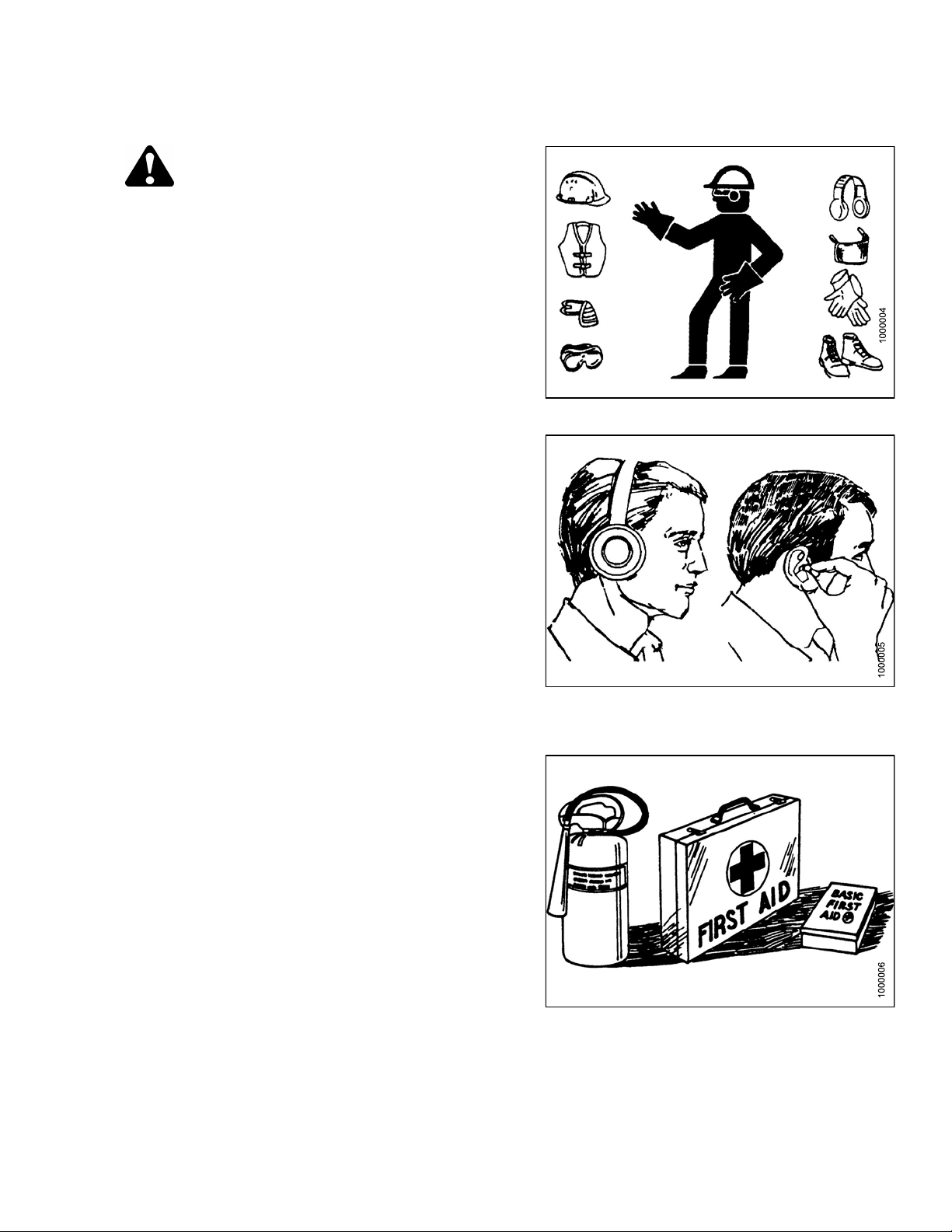
CAUTION
The following are general farm safety precautions
that should be part of your operating procedure
for all types of machinery.
Protect yourself
• When assembling, operating, and servicing machinery,
wear all the protective clothing and personal safety
devices that COULD be necessary for the job at hand.
Don’t take chances.
• You may need:
– A hard hat
– Protective footwear with slip resistant soles
– Protective glasses or goggles
– Heavy gloves
Figure 1.2
– Wet weather gear
– A respirator or filter mask
– Hearing protection
Be aware that exposure to loud noise can cause
impairment or loss of hearing. Wearing suitable
hearing protection devices such as ear muffs or ear
plugs. These will help protect against objectionable
or loud noises.
•Provideafirst aid kit for use in case of emergencies.
•Keepafire extinguisher on the machine. Be sure the fire
extinguisher is properly maintained. Be familiar with its
proper use.
• Keep young c hildren away from the machinery at
all times.
• Beaware that accidents often happen when theOperator
istiredorinahurrytogetfinished. Takethetimeto
consider the safest way. Never ignore warning signs
of fatigue.
Figure 1.3
Figure 1.
4
169254 3 Rev. D
Page 12
SAFETY
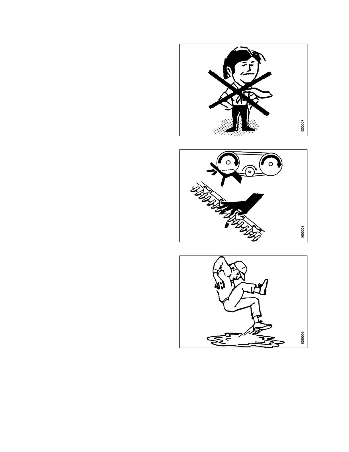
•Wearclosefitting clothing and cover long hair. Never
wear dangling items such as scarves or bracelets.
• Keep all shields in place. Never alter or remove safety
equipment. Make sure driveline guards can rotate
independently of the shaft and can telescope freely.
• Use only service and repair parts, made, or approved by
the equipment manufacturer. Substituted parts may not
meet strength, design, or safety requirements.
• Keep hands, feet, clothing, and hair away from moving
parts. Never attempt to clear obstructions or objects,
from a machine while the engine is running.
•Do NOT modify the machine. Non-authorized
modificationsmayimpair machine functionand/orsafety.
It may also shorten the machine’s life.
Figure 1.5
• Stop e ngine and remove key from ignition before leaving
operator’s seat for any reason. A child or even a pet
could engage an idling machine.
• Keep the area used for servicing machinery clean
and dry. Wet or oily floors are slippery. Wet spots
can be dangerous when working w ith electrical
equipment. Be sure all electrical outlets and tools are
properly grounded.
• Keep work area well lit.
• Keep machinery clean. Straw and chaff, on a hot
engine, are a fire hazard. Do NOT allow oil or grease to
accumulate on service platforms, ladders, or controls.
Clean machines before storage.
• Never use gasoline, naphtha, or any volatile material
for cleaning purposes. These materials may be toxic
and/or flammable.
• When storing machinery, cover sharp or extending
components to prevent injury from accidental contact.
Figure 1.6
Figure 1.7
169254
4
Rev. D
Page 13

SAFETY
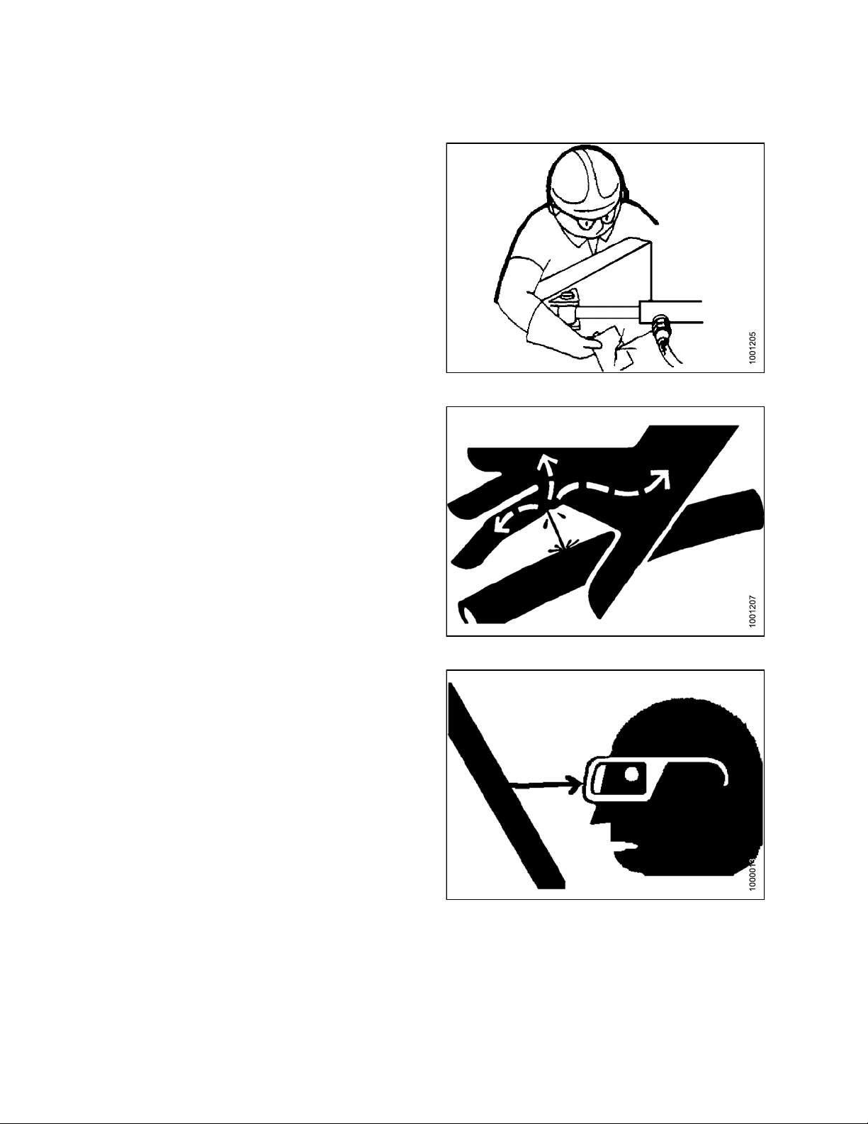
1.4 Maintenan
To ensure your
• Review the ope
operation and
•Placeallcon
brake, remov
partsto stop
• Follow good
– Keep servic
–Besureele
grounded.
– Use adequa
• Relieve pr
and/or dis
• Before ap
sure all c
and coupl
• Keephand
and/or r
safety while maintaining the machine:
rator’smanual and all safety itemsbefore
/or maintenance of the machine.
trolsin Neutral, stop the engine, set the park
e the ignition key, and wait for all moving
beforeservicing,adjusting,and/orrepairing.
shop practices:
e area clean and dry.
ctrical outlets and tools are properly
te light for the job at hand.
essure from hydraulic circuits before servicing
connecting the machine.
plying pressure to a hydraulic system, make
omponents are tight and that steel lines, hoses,
ings are in good condition.
s,feet, clothing, andhair away from all moving
otating parts.
ce Safety
Figure 1.8: Slip on Puddle
•Clearth
carryin
making a
•Instal
frame b
•Ifmore
same ti
mecha
acces
other
of dri
• Wear protective gear when working on the machine.
• Wear heavy gloves when working on knife components.
e area of bystanders especially children when
g out any maintenance and repairs or when
ny adjustments.
l transport lock or place safety stands under the
efore working under the hay conditioner.
than one person is servicing the machine at the
me,beawarethatrotatingadrivelineorother
nically driven component by hand (for example,
sing a lube fitting) will cause drive components in
areas(belts,pulleys, and knife)tomove. Stay clear
ven components at all times.
Figure 1.9: Keep Away
Figure 1.10: Safety Gear
169254 5 Rev. D
Page 14
SAFETY
1.5 Hydraulic
• Always place a
dismounting.
• Makesurethat
are kept in go
•Replaceanyw
hoses and ste
• Do not attem
lines, fitti
or welding.
extremely
suddenly a
• Wearprope
a high-pre
as a backs
aleak.
• If injure
hydrauli
Serious
hydraul
ngs, or hoses by using tapes, clamps, cements,
d by a concentrated high-pressure stream of
c fluid, seek medical attention immediately.
infection or toxic reaction can develop from
ic fluid piercing the skin.
ll hydraulic controls in Neutral before
all components in the hydraulic system
od condition and clean.
orn, cut, abraded, flattened, or crimped
el lines.
pt any makeshift repairs to the hydraulic
The hydraulic system operates under
high pressure. Such makeshift repairs will fail
nd create a hazardous and unsafe condition.
rhand and eyeprotectionwhen searching for
ssurehydraulic leak. Usea piece of cardboard
top instead of hands to isolate and identify
Safety
Figure 1.11: Checking Hydraulic Leaks
• Before
sure al
and co
Figure 1.12: Hydraulic Pressure Hazard
applying pressure to a hydraulic system, make
l components are tight and that steel lines, hoses,
uplings are in good condition.
Figure 1.13: Wear Safety Glasses
169254 6 Rev. D
Page 15
SAFETY
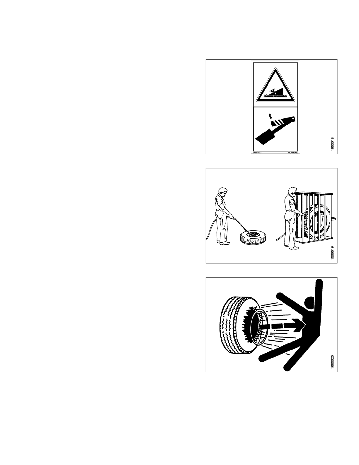
1.6 Tire Safet
• Failure to fol
on a wheel or ri
result in seri
•DoNOT atte
proper tra
low proper procedures when mounting a tire
m can produce an explosion that may
ous injury or death.
mpt to mount a tire unless you have the
ining and equipment.
y
Figure 1.14: Lower All Safety Stops
•Haveaq
ed tire maintenance.
requir
Figure 1.15: Safely Filling a Tire with Air
ualified tire dealer or repair service perform
Figure 1.16: Over-Inflation of Tire
169254
7
Rev. D
Page 16
SAFETY
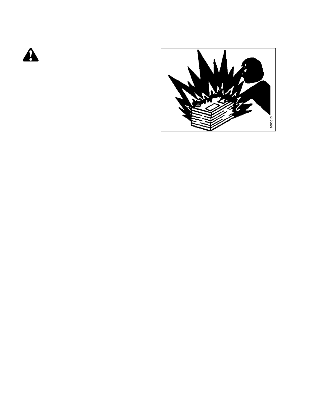
1.7 Battery Sa
WARNING
• Keep all spark
batteries, as
explosive.
•Ventilatewh
a gas given off by electrolyte is
en charging in enclosed space.
fety
sandflames away from the
Figure 1.17
169254 8 Rev. D
Page 17
SAFETY
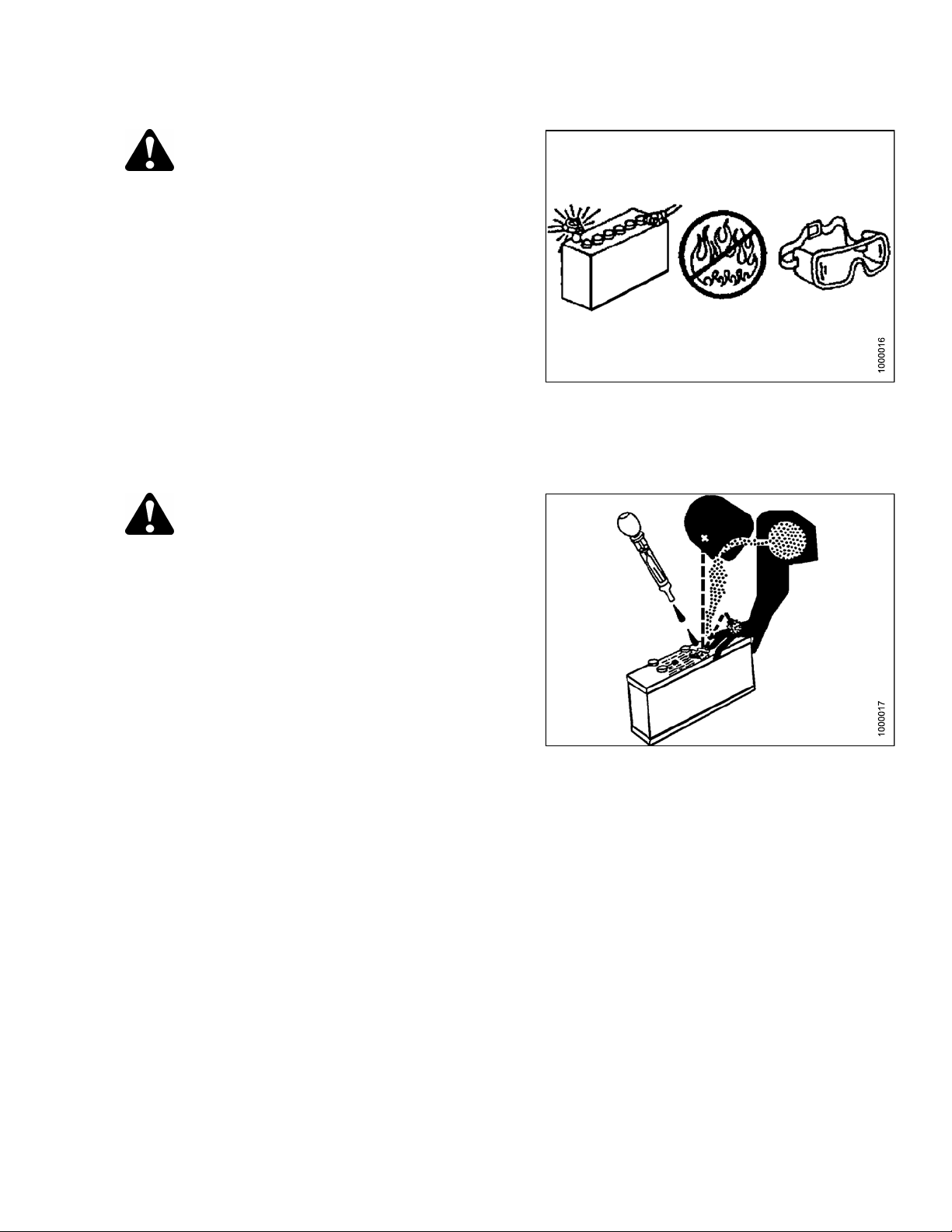
WARNING
• Wear safety glasses when working near
batteries.
• Do not tip batteries more than 45° to avoid
electrolyte loss.
• Battery electrolyte causes severe burns. Avoid
contact with skin, eyes, or clothing.
• Electrolyte splashed into the eyes is extremely
dangerous. Should this occur, force the eye
open, and floodwithcool,cleanwaterforfive
minutes. Call a doctor immediately.
• If electrolyte is spilled or splashed on clothing
or the body, neutralize it immediately with a
solution of baking soda and water, then rinse
with clear water.
Figure 1.18
WARNING
• To avoid injury from spark or short circuit,
disconnect battery ground cable before
servicing and part of electrical system.
• Do not operate the engine with alternator or
battery disconnected. With battery cables
disconnected and engine running, a high
voltage can be built up if terminals t ouch the
frame. Anyone touching the frame under these
conditions would be severely shocked.
• When working around storage batteries,
remember that all of the exposed metal parts
are live. Never lay a metal object across the
terminals because a spark or short circuit will
result.
• Keep batteries out of reach of children.
Figure 1.19
169254 9 Rev. D
Page 18

SAFETY
1.8 Welding Precautio n
High currents and voltage spikes associated with welding can cause damage to electronic components. Before
welding on any part of the windrower or an attached header, disconnect all electronic module harness connections
as well as the battery cables. Refer to your technical manual or MacDon Dealer for proper procedures.
169254 1
0
Rev. D
Page 19

SAFETY
1.9 Engine Saf
ety
WARNING
Do not use aerosol types of starting aids such as ether. Such use could result in an explosion and
personal injury.
CAUTION
• In the initial start-up of a new, serviced, or repaired engine always make provision to shut the
engine off, in order to stop an over-speed. This may be accomplished by shutting off the air and/or
fuel supply to the engine. Over-speed shut down should occur automatically for engines that are
controlled electronically.
• Do not bypass or disable the automatic shutoff circuits. The circuits are provided in order to help
prevent personal injury. The circuits are also provided in order to help prevent engine damage. See
the technical manual for repairs and adjustments.
• Inspect the engine for potential hazards.
• Before starting the engine, ensure that no one is on, underneath, or close to the engine. Ensure that
theareaisfreeofpersonnel.
• Allprotective guards and all protective covers m ust be installed if the engine must be started in order
to perform service procedures.
• To help prevent an accident that is caused by parts in rotation, work around the parts carefully.
• If a warning tag is attached to the engine start switch or to the controls, do NOT start the engine
or move the controls. Consult with the person who attached the warning tag before the engine is
started.
• Start the engine from the operator’s compartment. Always start the engine according to the
procedure that is described in the Engine Starting section of the operator’s manual. Knowing
the correct procedure will help to prevent major damage to the engine components and prevent
personal injury.
• To ensure that the jacket water heater (if equipped) and/or the lube oil heater (if equipped) is working
correctly, check the water temperature gauge and/or the oil temperature gauge during the heater
operation. Engine exhaust contains products of combustion which can be harmful to your health.
Always start the engine and operate the engine in a well ventilated area. If the engine is started in an
enclosed area, vent the engine exhaust to the outside.
NOTE: The engi
cold con
equipp
ne may be equipped with a device for cold starting. If the engine will be operated in very
ditions, then an additional cold starting aid may be required. Normally, the engine will be
ed with the correct type of starting aid for your region of operation.
1.9.1 High Pressure Rails
CAUTION
Contact with high pressure fuel may cause fluid penetration and burn hazards. High pressure fuel spray
may cause a fire hazard. Failure to follow these inspection, maintenance and service instructions may
cause personal injury or death.
169254
1
1
Rev. D
Page 20

SAFETY
1.9.2 Engine Electronics
WARNING
Tampering with the electronic system installation or the Original Equipment Manufacturer (OEM) wiring
installation can be dangerous and could result in personal injury or death and/or engine damage.
WARNING
Electrical Shock Hazard. The electronic unit injectors use DC voltage. The Electronic Control Module
(ECM) sends this voltage to the electronic unit injectors. Do not come in contact with the harness
connectorfor the electronic unit injectorswhilethe engine is operating. Failure to follow this instruction
could result in personal injury or death.
This engine has
the engine oper
initiate an im
The following
• Warning
• Derate
• Shutdown
The followin
• Engine Cool
• Engine Oil P
• Engine Spee
• Intake Man
The engine
the monito
will provi
mediate action.
actions are available for engine monitoring control:
g monitored en gine operating conditions have the ability to limit engine speed and/or the engine power:
ifold Air Temperature
monitoring package can vary for different engine models and different engine applications. However,
ring system and the engine monitoring control will be similar for all engines. Together, the two controls
de the engine monitoring function for the specific engine application.
a comprehensive, programmable engine monitoring system. The ECM has the ability to monitor
ating conditions. If any of the engine parameters extend outside an allowable range, the ECM will
ant Temperature
ressure
d
169254
2
1
Rev. D
Page 21
SAFETY
1.10 Safety Si
• Keep safety si
• Replace safet
become illegi
•Iforiginalp
replaced, be
safety sign.
• Safety sign
Parts Depar
ble.
arts on which a safety sign was installed are
sure the repair part also bears the current
s are available from your Dealer
tment.
gns
gns clean and legible at all times.
y signs that are missing or
1.10.1 Installing Safety Decals
To install a safety decal, follow these steps:
1. Be sure the installation area is clean and dry.
Figure 1.20: Read Operator’s Manual before
Operating
2. Decide on the exact location before you remove the decal backing paper.
3. Remove the smaller portion of the split backing paper.
4. Place the sign in position and slowly peel back the remaining paper, smoothing the sign as it is applied.
5. Small air pockets can be smoothed out or pricked with a pin.
169254 1
3
Rev. D
Page 22

Page 23
2 General Information
2.1 Torque Specifications
The following tables give correct torque values for various bolts, cap screws, and hydraulic fittings.
• Tighten all bolts to the torques specified in chart (unless otherwise noted throughout this manual).
• Replace hardware with the same strength and grade bolt.
• Check tightness of bolts periodically, using the tables below as a guide.
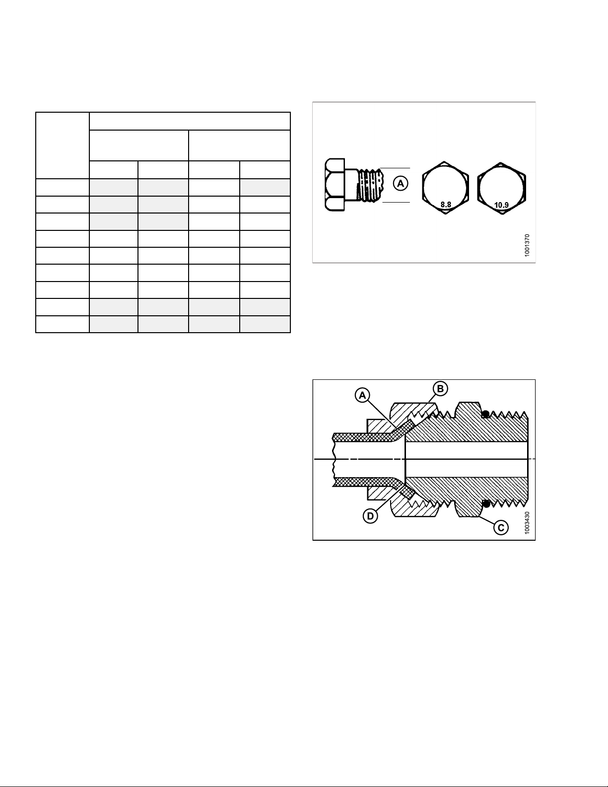
• Torque categories for bolts and cap screws are identified by their head markings.
2.1.1 SAE Bolt Torque Specifications
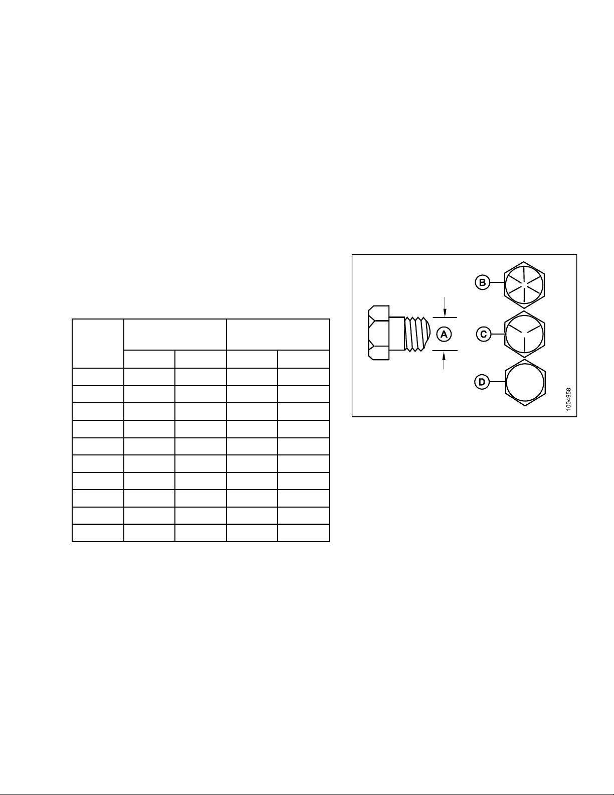
Torque values shown inthistableare valid for non-greased,
ornon-oiledthreadsand heads. Therefore,doNOT grease
or oil bolts or cap screws unless otherwise specified in
this manual.
Table 2.1 SAE Grade 5 Bolt and Grade 5 Free Spinning
Nominal
Torque (ft·lbf)
(*in·lbf)
Torque (N·m)
Size (A)
Min. Max. Min. Max.
1/4-20 *106 *117
5/16-18 *218 *241
3/8-16
7/16-14
1/2-13
9/16-12
5/8-11
3/4-10
7/8-9
1-8 611 676 825 912
32 36 44 48
52
79 87 106 118
114 126 153 170
157 173 212 234
281 311 380 420
449 496 606 669
57
11.9 13.2
24.6 27.1
70
77
Figure 2.1
A-NominalSize B-SAE-8
5
C - SAE-
D - SAE-
2
169254 1
5
Rev. D
Page 24
GENERAL INFORMATION
Table 2.2 SAE Grade 5 Bolt and Grade 5 Distorted Thread Nut
Nominal
Torque (ft·lbf)
(*in·lbf)
Torque (N·m)
Size (A)
Min. Max. Min. Max.
1/4-20 *72 *80
5/16-18 *149 *164
3/8-16
7/16-14
1/2-13
9/16-12
5/8-11
3/4-10
7/8-9
1-8 459 507 619 684
Table 2.3 SAE Grade 8 Bolt and Grade 8 Distorted Thread Nut
22 24 30 33
35 39 48 53
54 59 73 80
77
107 118 144 160
192 212 259 286
306 338 413 456
86 105 116
Torque (ft·lbf)
Nominal
(*in·lbf)
8.1 9
16.7 18.5
Torque (N·m)
Size (A)
Min. Max. Min. Max.
1/4-20 *150 *165
5/16-18
3/8-16
7/16-14
1/2-13
9/16-12
1
5/8-1
3/4-10
7/8-9
1-8 647 716 874 966
18 19 24 26
31 34 42 46
50
76 84 102 113
109 121 148 163
151 167 204 225
268 296 362 400
432 477 583 644
55
16.8 18.6
67 74
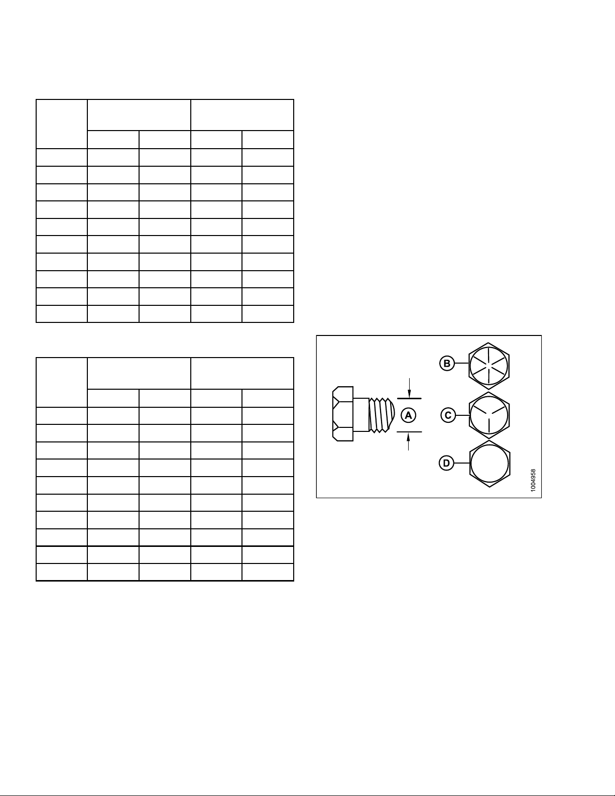
Figure 2.2
A-Nomina
C - SAE-5 D - SAE-2
lSize
B - SAE-8
169254 1
6
Rev. D
Page 25
GENERAL INFORMATION
Table 2.4 SAE Grade 8 Bolt and Grade 8 Free Spinning Nut
Nominal
Torque (ft·lbf)
(*in·lbf)
Torque (N·m)
Size (A)
Min. Max. Min. Max.
1/4-20 *150 *165
5/16-18
3/8-16
7/16-14
1/2-13
9/16-12
5/8-11
3/4-10
7/8-9
1-8 863 954 1165 1288
26 28 35 38
46 50 61 68
73 81 98 109
111 123 150 166
160 177 217 239
221 345 299 330
393 435 531 587
633 700 855 945
16.8 18.6
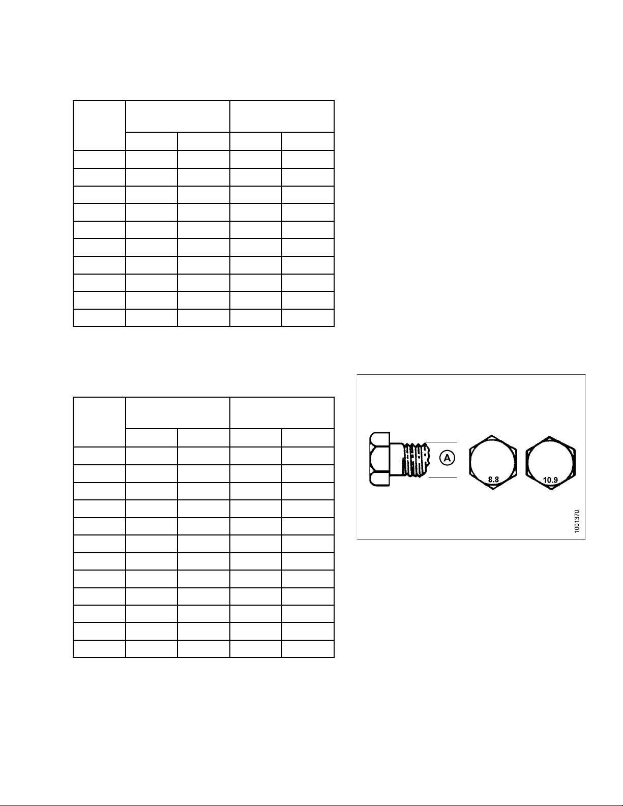
2.1.2 Metric Bolt Specifications
Table2.5MetricClass8.8BoltsandClass9Free Spinning Nut
Nominal
Size
Torque (ft·
(*in·lbf)
Min. Max. Min. Max.
lbf)
Torque (N·
m)
3-0.5
3.5-0.6
4-0.7
5-0.8
6-1.0
8-1.25 20 23 28 30
5
10-1.
12-1.75 70 78 95 105
14-2.0 113 124 152 168
.0
16-2
20-2.5 341 377 460 509
24-3.0 589 651 796 879
*13 *14
*20 *22
*29 *32
*59 *66
*101 *112
40 45
175 193 236 261
1.4 1.6
2.2 2.5
3.3 3.7
6.7 7.4
11.4 12.6
55
60
Figure 2.3
A-NominalSize
169254
7
1
Rev. D
Page 26

GENERAL INFORMATION
Table2.6MetricClass8.8BoltsandClass9Distorted Thread Nut
Nominal
Torque (ft·lbf)
(*in·lbf)
Torque (N·m)
Size
Min. Max. Min. Max.
3-0.5
3.5-0.6
4-0.7
5-0.8
6-1.0
8-1.25
10-1.5 28 30 37 41
12-1.7548536572
14-2.0
16-2.0 119 132 161 178
20-2.5 233 257 314 347
24-3.0 402 444 543 600
Table 2.7 Metric Class 10.9 Bolts and Class 10 Free Spinning Nut
Nominal
*9 *10
*14 *15
*20 *22
*40 *45
*69 *76
*167 *185
77
Torque (ft·
85 104 115
lbf)
(*in·lbf)
11.1
1.5 1.7
2.3 2.5
4.5
7.7
18.8 20.8
Torque (N·m
5
8.6
)
Size
Min. Max. Min. Max.
3-0.5
3.5-0.6
4-0.7
5-0.8
6-1.0
8-1.25 28 31 38 42
5
10-1.
12-1.75 97 108 132 145
14-2.0 156 172 210 232
.0
16-2
20-2.5 472 521 637 704
24-3.0 815 901 1101 1217
*18 *19
*27 *30
*41 *45
*82 *91
*140 *154
56 62
242 267 326 360
1.8 2
2.8 3.1
4.2 4.6
8.4 9.3
14.3 15.8
75
83
169254 1
8
Rev. D
Page 27

GENERAL INFORMATION
Table 2.8 Metric Class 10.9 Bolts and Class 10 Distorted Thread Nut
Nominal
Size
Torque
(ft·lbf)(*in·lbf)
Min. Max. Min. Max.
Torque (N·m)
3-0.5
3.5-0.6
4-0.7
5-0.8
6-1.0
8-1.25 19 21 26 29
10-1.5 38 42 51
12-1.7566739099
14-2.0 106 117 143 158
16-2.0 165 182 222 246
20-2.5 322 356 434 480
0
24-3.
*12 *13
*19 *21
*28 *31
*56 *62
*95 *105
556 614 750 829
1.3 1.5
2.1 2.3
3.1 3.4
6.3
10.7 11.8
7
57
169254 1
9
Rev. D
Page 28
GENERAL INFORMATION
2.1.3 Metric Bolt Specifications Bolting into Cast Aluminum
Table 2.9 Metric Bolt Bolting into Cast Alu minum
Bolt Torque
Nominal
Size
8.8
(Cast Alumin
um)
(Cast Alumin
10.9
um)
ft·lbf N·m ft·lbf N·m
M3 1
M4 2.6 4
M5
M6 6 9 9 12
M8 14 20 20 28
M10 28 40 40
M12 52 70 73 100
M14
M16
5.5
8
55
2.1.4 Flare-Type Hydraulic Fittings
1. Check flare and flare seat for defects that might
cause leakage.
2. Align tube with fitting before tightening.
Figure 2.4
A-NominalSize
3. Lubricate connection and hand-tighten swivel nut
until snug.
4. To prevent twisting the tube(s), use two wrenches.
Place one wrench on the connector body and with the
second, tighten the swivel nut to the torque shown.
Figure 2.5
A - Flare B - Nut
C - Flareseat
D - Body
169254 2
0
Rev. D
Page 29
GENERAL INFORMATION
Table 2.10 Flare-Type Hydraulic Tube Fittings
Nut Size
Across
Flats (in.)
SAE No.
Tube Size
O.D. (in.)
Thread
Size (in.)
Torque Value
ft·lbf
1
Flats From Finger
Tight (FFFT)
N·m Flats Turns
3
4 1/4 7/16 9/16 9 12 1 1/6
5
6
8 1/2 3/4 7/8 34 46 1 1/6
10
12
14 7/8 1-3/8 1-3/8 90 122 3/4 1/8
16 1
3/16 3/8 7/16
5/16 1/2 5/8
3/8 9/16 11/16
5/8 7/8
3/41-1/161-1/4
1-5/16 1-1/2
146621
681
12 16 1
18 24 1
75
105 142
102
3/4 1/8
3/4 1/8
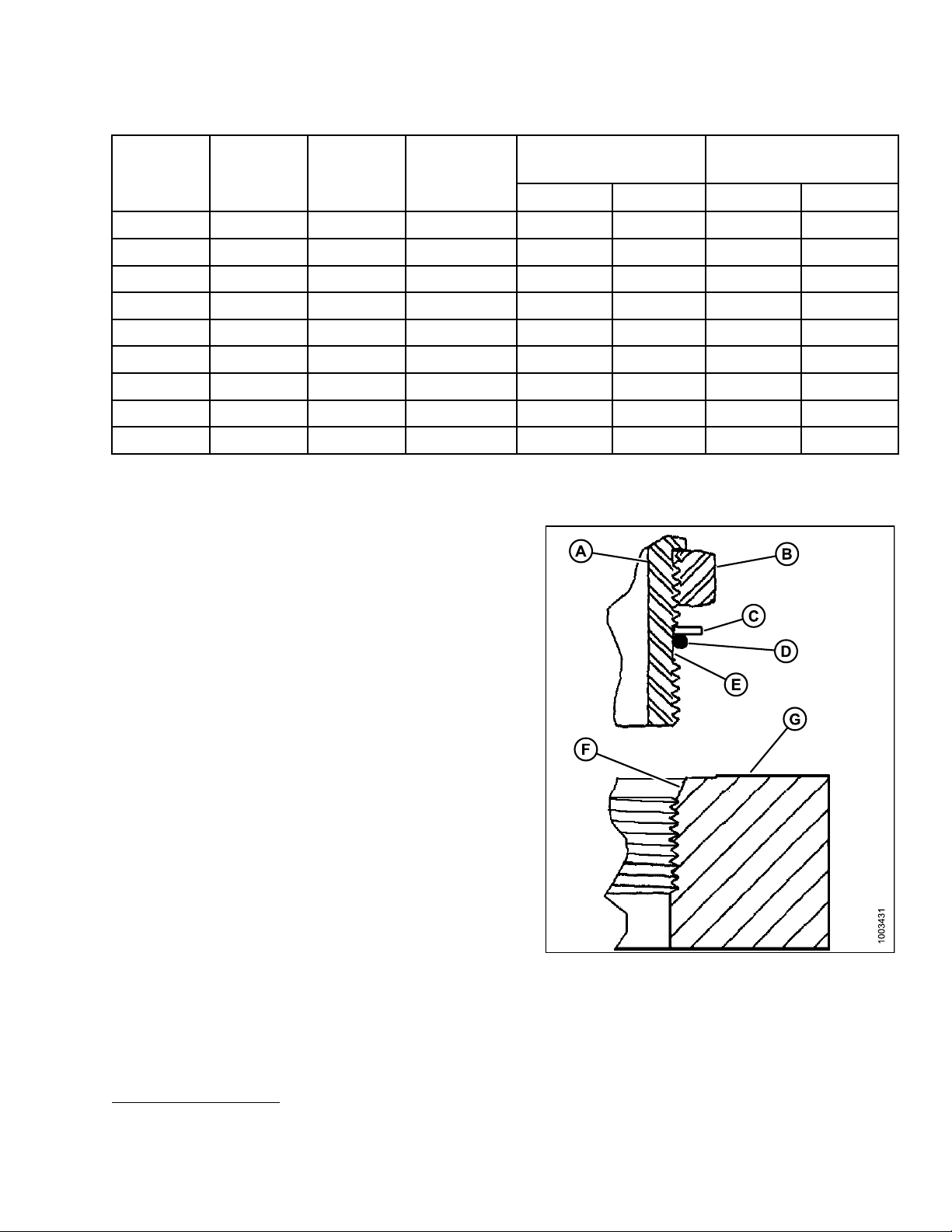
2.1.5 O-Ring Boss (ORB) Hydraulic Fittings
1. Inspect O-ring (D) and seat (F)for dirt or obvious
defects.
2. On angle fittings, back off the lock nut (B) until washer
(C) bottoms out at top of groove (E) in fitting (A).
3. Hand-tighten fitting until back up washer (C) or washer
face (if straight fitting) bottoms on part face (G) and
O-ring is seated.
1/6
1/6
1/6
1/6
4. Position angle fittingsby unscrewing NO MORE THAN
one turn.
5. Tighten straight fittings to torque shown.
6. Tighten angle fittings to torque shown in table 2.11
O-Ring Boss (ORB) Hydraulic Fittings (Adjustable),
page 22, while hold ing body of fitting with a wrench.
Figure 2.6
A - Fitting B - Lock Nut
D - O-Ring E - Groove F - Seat
1. Torque values shown are based on lubricated connections as in reassembly.
C - Washer
169254
1
2
Rev. D
Page 30
GENERAL INFORMATION
Table 2.11 O-Ring Boss (ORB) Hydraulic Fittings (Adjustable )
SAE No.
Thread
Size (in.)
Nut Size Across
Flats (in.)
Torque Value
ft·lbf N·m Flats Turns
2
Flats From Finger Tight (FFFT)
3
3
4
5
6
8
10
12
16
20
24
3/8 1/2
7/16 9/16
1/2 5/8
9/16 11/16
3/4 7/8
7/8
1-1/16 1-1/4
1-5/16 1-1/2
1-5/8 1-7/8
1-7/8 2-1/8
14662
68 2
912 2
12 16 2
18 24 2
34 46 2
75
105 142
140 190
160 217
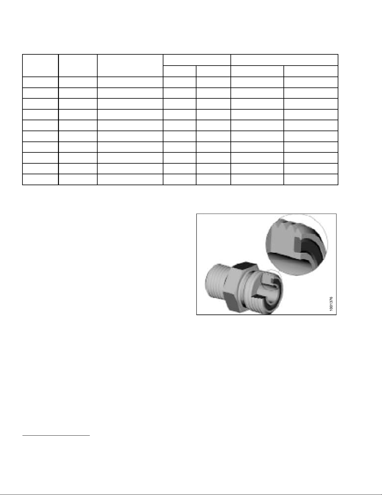
2.1.6 O-Ring Face Seal (ORFS) Hydraulic Fittings
1. Check components to ensure that the sealing surfaces
and fitting threads are free of burrs, nicks, and
scratches or any foreign material.
1-1/2 1/4
102 1
3/4 1/8
3/4 1/8
1/2 1/12
1/3
1/3
1/3
1/3
1/3
1/6
gure 2.7
Fi
2. Torque values shown are based on lubricated connections as in reassembly.
3. Always default to the torque value for evaluation of adequate torque.
169254
2
2
Rev. D
Page 31

GENERAL INFORMATION
2. Apply hydraulic system oil to the O-ring.
3. Align the tube or hose assembly. Ensure that flat face
of the mating flange comes in full contact with O-ring.
4. Thread tube or hose nut until hand-tight. The nut
should turn freely until it is bottomed out.
5. Torque fittingfurthertoagiventorquevalueintable
2.12 O-Ring Face Seal (ORFS) Hydraulic Fittings,
page 23.
NOTE: If applicable, always hold the hex on the
fitting body to prevent unwanted rotation
of fitting body and hose when tightening
the fitting nut.
6. When assembling unions or two hoses together, three
wrenches will be required.
7. Check the final condition of the fitting.
Table 2.12 O-Ring Face Seal (ORFS) Hydraulic Fittings
SAE
No.
3
Thread
Size (in.)
6
Tube O.D.
(in.)
3/16
Torque Value
ft·lbf
––––
Figure 2.8
A - Brazed Sleeve B - O-Ring
C-TwoPiec
E - Fitting Body
e Sleeve
4
D-Nut
Flats From Finger Tight
(FFFT)
N·m Tube Nuts
5
Swivel &
Hose
4 9/16 1/4 11–12 14–16 1/4–1/2 1/2–3/4
5
6
6
5/16
11/16 3/8
8 13/16 1/2 32–35 43–47
10 1
12
1-3/16 3/4
5/8
––––
18–20 24–27
1/2–3/4
45–51 60–68
67–71 90–95
1/4–1/2
14 1-3/16 7/8 67–71 90–95
16
20
1-7/16
1-11/16 1-1/4
24 2 1-1/2 148–16
32
2-1/2
1 93–100 125–135
126–141 170–190
7
2
––––
200–22
1/3–1/2
5
4. Torquevaluesandanglesshownarebasedonlubricated connection, as in reassembly.
5. Always default to the torque value fo r evaluation of adequate torque.
6. O-ring face seal type end not defined for this tube size.
169254 2
3
Rev. D
Page 32

GENERAL INFORMATION
2.2 Specificat
NOTE: Specifications and design are subject to change without notice or obligation to revise previously
sold units.
ions
Item Specification
Frame & Structure
Total Weight (estimated) 1700 lb (770 kg)
Carrier MacDon M150, M155, and M200 Self-Propelled Windrowers
Manual Storage In Windrower Cab
Drives
Main Conditioner 3.16 cu in. (51.83 cc) Hydraulic Motor with 1.29 cu in. (21.14 cc) Flow
Divider
Feed Deck
Connections Flat Faced Quick Attach Couplers – Connect Under Pressure
Normal
Operating
Pressure
Conditioner
Drive
Conditioner 2500-3000 psi (17.0–20.7 MPa)
Feed Deck
4.0 c u in. (65 cc) Hydraulic Motor with 921 psi Relief
600 psi (4.1 MPa)
Hydraulic Motor To Belt Driven Roll To Open Timing Gear System
Roll Type
Roll Diameter
Roll Length
Header Size 15 ft 20 ft & 25 ft 30 ft 35 ft
Roll Speed
Feed Draper Speed 437–553 fpm 407–495 fpm 393–525 fpm 393–491 fpm
Swath Width 36-102 in. (915-2,540 mm)
Forming Shields Header Mounted Tractor Supported Adjustable Forming Shield System
NOTE: To avoid excessive vibration and poor performance, the HC10 Hay Conditioner should not be
attached to single-knife drive headers.
Intermeshing Steel Bars
9.17 in. (233 mm)/6.63 in. (168.4 mm) OD Tube
72 in. (1830 mm)
772–977 rpm 720–874 rpm 695–927 rpm 695–868 rpm
169254
4
2
Rev. D
Page 33

GENERAL INFORMATION
2.3 Conversio
Quantity
Area
Flow
Force
Length
Power horsepower hp x 0.7457 = kilowatts kW
Pressure
Torque
nChart
Inch-Pound Units
Unit Name Abbreviation
acres acres
US gallons per
minute
pounds force lbf
inch in. x 25.4 = millimeters
foot ft.
pounds per
square inch
pound feet or
foot pounds
pound inches or
inch pounds
gpm
psi
ft·lbf
in·lbf
Factor
x 0.4047 = hectares ha
x 3.7854 = liters per minute
x 4.4482 = Newtons N
x0.305=
x 6.8948 = kilopascals kPa
x .00689 = megapascals MPa
÷ 14.50
x 1.3558 =
x 0.1129 =
38 =
SI Units (Metric)
Unit Name Abbreviation
meters
bar (non-SI) bar
newton meters
newton meters
L/min
mm
m
N·m
N·m
Temperature
Velocity
olume
V
Weight pounds lbs x 0.4536 = kilograms kg
degrees
fahrenheit
feet per minute ft/min
feet per second ft/s
miles per hour mph x 1.6063 =
US gallons US gal
ounces oz.
cubic inches in.
˚F(˚F-32) x 0.56 =
x 0.3048 =
x 0.3048 =
x 3.7854 = liters L
x 29.5735 = milliliters ml
3
x 16.3871 =
Celsius
meters per
minute
meters per
second
kilometres per
hour
cubic
centimetres
m/min
km/h
cm
˚C
m/s
3
or cc
169254 2
5
Rev. D
Page 34

GENERAL INFORMATION
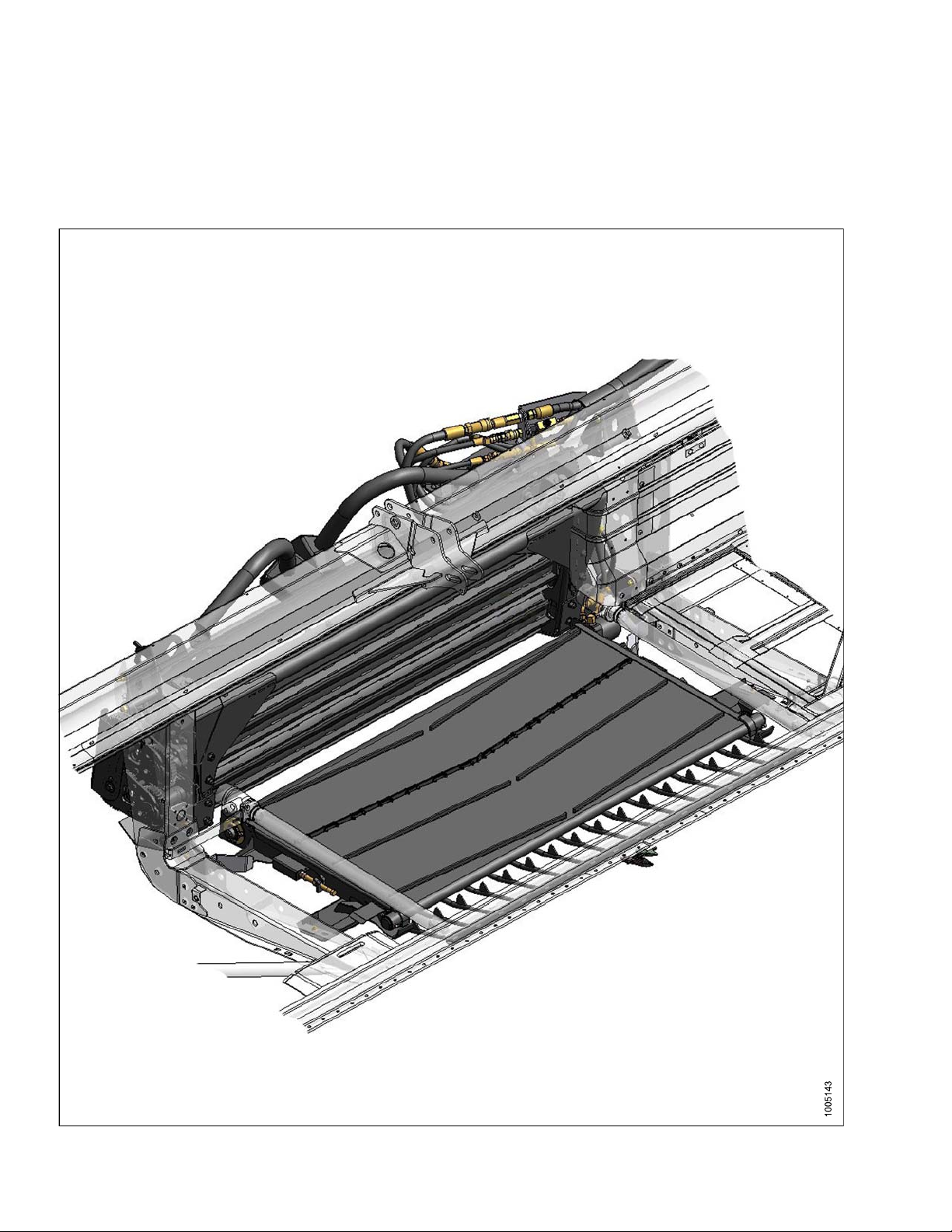
2.4 Component
Identification
Figure 2.9: Back View of Hay Conditioner Installed in Header
A - Hydraulics To Header
g Gears
E-Timin
B - Lift Arms C - Roll Timing Tool D - Stand
F - L-Pins
G-Hydra
ulic Motor
169254 2
6
Rev. D
Page 35

GENERAL INFORMATION
Figure 2.10: Back View of Hay Conditioner Installed in Header
A - Spacer
E - Spacer
B - Mounti
F-Rolls
ng Bracket
C-LiftingLugs
G - Drive Belt Shield
D - Mounti
ng Bracket
re 2.11: Front View of Hay Conditioner Installed in Header
Figu
A - Mounting Bracket
E - Rock Grate
169254
B - Roll Gap Adjusters C - Feed Deck Motor
F - Feed Deck
G - Draper Tension Adjusters (2)
7
2
D - Mounting Bracket
Rev. D
Page 36

GENERAL INFORMATION
Figure 2.12: Swath Forming Shield
A-SideDeflector Adjusters B - Side Deflectors C - Height Adjust Strap D - Fluffer Shield
E-Deflector Fins
169254 2
8
Rev. D
Page 37

3 Unloading and Assembly
To unload and assemble an HC10 Hay Conditioner, follow each of the procedures in this chapter in order.
3.1 Unloading the Hay Conditioner
CAUTION
To avoid injury to bystanders from being struck
by machinery, do not allow people to stand in
unloading area.
CAUTION
Equipment used for unloading must meet or
exceed the requirements specifie d below. Using
inadequate equipment may result in vehicle
tipping or machine damage.
Lifting Vehicle
Minimum Lifting
Capacity
Minimum Fork Length
7
2000 lb (908 kg)
60 inches (1524 mm)
IMPORTANT
Forklifts are normally rated for a load located 24
inches (610 mm) ahead of back end of the forks.
To obtain the forklift capacity at 48 inches (1220
mm), check with your forklift distributor.
WARNING
Be sure forks are secure before moving away from
load. Stand clear when lifting.
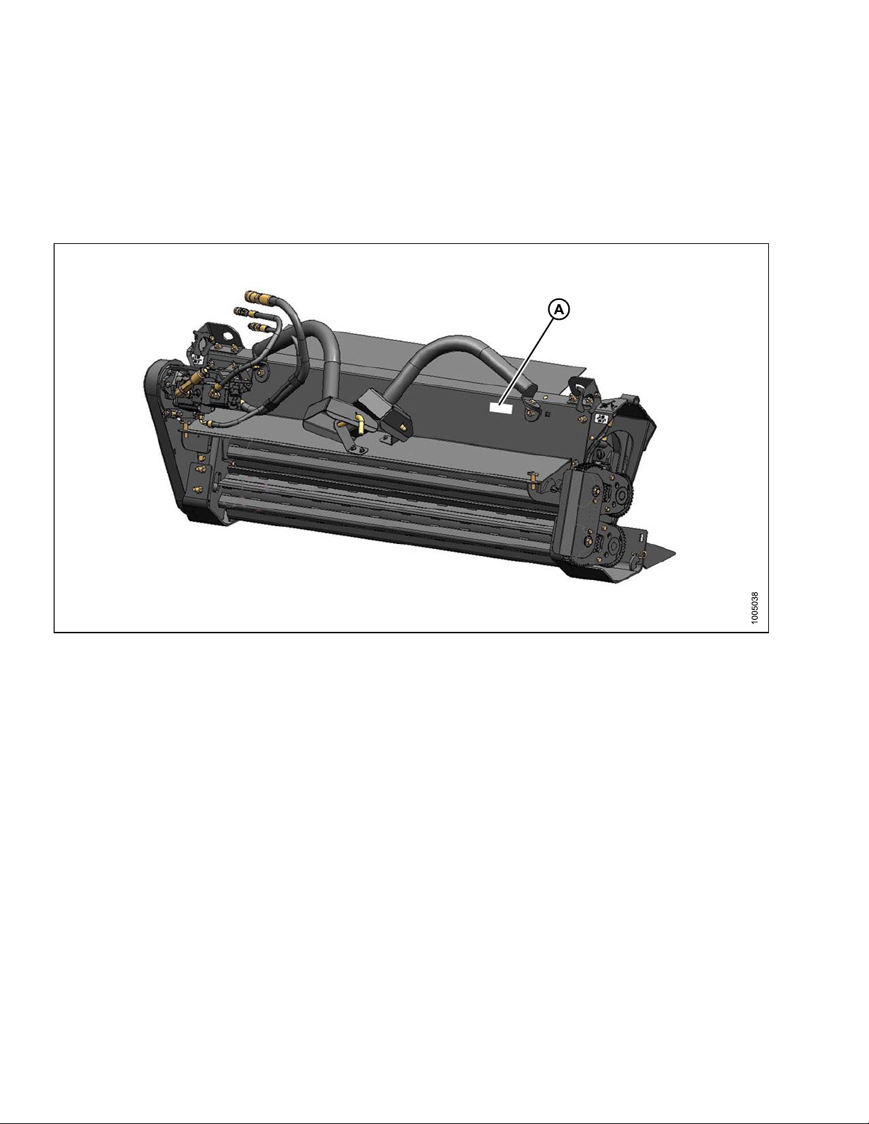
Figure 3.1: Hay Conditioner Bundle #4798
Figure 3.2: Feed Deck Bundle #4799
7. At 48 inches (1220 mm) from back end of forks.
169254 2
9
Rev. D
Page 38

UNLOADING AND ASSEMBLY
To unload the hay conditioner, follow these steps:
1. Remove hauler's tie down straps and chains.
2. Use forklift to lift each of the three pallets of hay
conditioner components off of the trailer deck.
3. Back up until unit clears trailer and slowly lower to 6
inches (150 mm) from ground.
4. Take to storage or set-up area.
5. Set pallet down securely on level ground.
6. Check for shipping damage and missing parts.
Figure 3.3: Forming Shield Bundle #4800
169254 3
0
Rev. D
Page 39

UNLOADING AND ASSEMBLY
3.2 Preparing the Header
To prepare the draper header for installation of the hay
conditioner, follow these steps:
1. Adjust the header stand (A) to mid-position.
2. Trim poly deflector along creased line (A) on back of
poly for proper fit up to conditioner.
Figure 3.4
Figure 3
.5
169254 3
1
Rev. D
Page 40

UNLOADING AND ASSEMBLY
3.3 Installin
To install the
1. Unpa ck feed de
2. Pos ition roc
3. Lift rock grate(A), and position the rear tabs (C) so they
slide over the header leg flanges.
4. Position the front lip (B) of rock grate (A) in front of the
bottom edge of the cutterbar, and slide forward so it
engages the cutterbar.
5. If the header is equipped with cutterbar poly, set the
rock grate on top of the poly in front of the cutterbar,
then push down, and forward to seat the rock grate
onto the cutte rbar.
6. Ensure ro ck grate is p ushed fully forward, and secure
with two bolts installed from underside. Tighten bolts.
g the Rock Grate
rock grate, follow these steps:
ck / rock grate bundle.
k grate into center area of header.
Figure 3.6
169254 3
2
Figure 3.7
Rev. D
Page 41

UNLOADING AND ASSEMBLY
3.4 Installing Deck Brackets
To install the deck brackets onto the header, follow
these steps:
1. Install thetwo lower brackets(A) onto the inside ofboth
center header legs with two bolts and nuts (B) in each
bracket.
2. Install right-hand upper bracket (A) and spacer (B) on
the right-hand center leg as shown and install nut (C).
Figure 3.8
NOTE:
3. Install t
and secur
4. Tighten b
5. Install the left-hand upper bracket (A) and spacer (B)
onto the inboard side of left-hand center leg as shown.
For header
cover,ins
he other bolt through the bracket and spacer
ewithanut(D).
oth bolts.
s with a sheet metal hose
tallbolts from theoutboard side.
Figure 3
.9: 15 ft Header Shown
169254 3
re 3.10
Figu
3
Rev. D
Page 42

UNLOADING AND ASSEMBLY
6. Remove the hose guide (A) located near the left-hand
center leg. (For 20 ft. and larger headers, remove this
support from its mounting position on sheet metal hose
cover.)
7. Attach hose assembly (A) onto the left-hand center leg
and install nut on lower bolt (C). Ensure correct hole is
used when attaching hose assembly (use hole (D) for
15-foot headers).
NOTE:
8. Instal
assemb
9. Tighte
For head
cover, i
l other bolt (B) through bracket, spacer, and hose
ly and secure with a nut.
n both bolts.
ers with a sheet metal hose
nstallbolts from the outboard side.
Figure 3.
Figur
A - Hose Assembly B - Bolt
C - Mounting Position for 20–35-Foot Headers
D - Mounting Position for 15-Foot Headers
11: 15 ft Header Shown
e 3.12: 20–35 ft Header Shown
169254 3
4
Rev. D
Page 43

UNLOADING AND ASSEMBLY
3.5 Installing the Feed Deck
To install the feed deck, follow these steps:
1. Slide feed deck (A) under header opening from the
rear. Deck drive motor faces aft.
2. Set front of deck (A) onto the rock grate and slide the
feed deck forward until the locating pins (B) reach the
pockets on the rock grate.
3. Lift the rear of the feed deck so the mounts on the
deck clear the brackets on the leg and slide deck
forward until mounting pins are fully positioned inside
the pockets.
Figure 3.13
4. Install two 1/2 x 1.25 in. long carriage bolts at rear
mounting brackets.
Figure 3
Figu
.14
re 3.15: LH Side Shown
169254 3
5
Rev. D
Page 44

UNLOADING AND ASSEMBLY
Figure 3.16: RH Side Shown
5. Attach the
with two 3/
6. Adjust hea
2-1/2 to 3
manual fo
hose bracket (A) to the mounting bracket
8 x 1.0 in. long carriage bolts (B).
der side drapers to overlap feed deck by
inches(65 to 75 mm). See header operator’s
rprocedure.
Figure 3.17
169254 3
6
Rev. D
Page 45

UNLOADING AND ASSEMBLY
3.6 Installin
Therearetwom
• The lifting me
• The tractor m
3.6.1 Instal
g the Conditioner
ethods for installing th e conditioner:
thod
ethod
ling Conditioner: Lifting Method
CAUTION
Equipment used for unloading must meet or
exceed the requirements specifie d below. Using
inadequate equipment may result in vehicle
tipping or machine damage.
Lifting Vehicle
Minimum Lifting
Capacity
Minimum Fork Length
8
2000 lb (908 kg)
60 inches (1524 mm)
IMPORTANT
Forklifts are normally rated for a load located 24
inches (610 mm) ahead of back end of the forks.
To obtain the forklift capacity at 48 inches (1220
mm), check with your forklift distributor.
Chain Type Overhead L
Quality (
Minimum Working Load
To install the conditioner using the lifting method, follow
these steps:
1. Attach chain to lifting brackets (A) on conditioner, and
secure chain to lifting device (B).
2. Lift conditioner to upright position.
3. Remove shipping blocks if present.
4. Position conditioner into header opening from the rear.
5000 lb (2270 kg)
ifting
1/2 inch)
Figure 3.18
8. At 48 inches (1220 mm) from back end of forks.
169254 3
7
Rev. D
Page 46

UNLOADING AND ASSEMBLY
5. Carefully lower the windrower lift legs until lugs (A) on
conditioner are seated in the U-shaped brackets (B)
on header.
6. Ensure the conditioner is seated properly in the
brackets, and then remove the chains.
7. Install 5/8 in. x 1-1/2 in. carriage bolt (A) in th e
right-hand lower attachment location.
Figure 3.19
8. Install 5/8 in. x 1-1/2 in. carriage bolt (A) in th e
left-hand lower attachment location.
Figure 3.20: RH Side Shown
Figure 3.21: LH Side Shown
169254 3
8
Rev. D
Page 47

UNLOADING AND ASSEMBLY
9. Reconnect the five hydraulic hoses between the
conditioner and the header as follows:
• Small male quick-disconnect from motor to
header (A)
• Large female quick-disconnect from motor to
header (B)
• Small female quick-disconnect from deck to
header (C)
• Small female quick-disconnect from motor to
deck (D)
• Large female quick-disconnect from header to
motor (E)
3.6.2 Installing Conditioner: Windrower Method
Figure 3.22
A - Case Drain B - Cond itioner Motor Pressure
C - Deck Moto
E - Conditioner Motor Return
rReturn
D - Deck Motor Pressure
To install the conditioner using the windrower method,
follow these steps:
1. Lower header stand to mid-position (A).
2. Attach chain (A) to li
and secure chain to l
3. Lift off of shipping
in upright position
fting brackets (B) on conditioner
ifting device.
pallet and set conditioner on ground
.
Figure 3.23
169254 3
9
Figure 3.24
Rev. D
Page 48

UNLOADING AND ASSEMBLY
4. Retrieve stand (A) and hairpin (B) from conditioner
bundle #4798 and install stand in slot in base at lower
right-hand end of conditioner. Secure stand with
hairpin.
5. Remove shipping blocks if present.
6. Hardware at lifting arms has been tightened for
shipping. Loosen two bolts (A) per side just enough to
allow arms (B) to swing out.
Figure 3.25
Figure 3.26: LH Shown
Figure 3.27: RH Shown
169254 4
0
Rev. D
Page 49

UNLOADING AND ASSEMBLY
7. Remove L-pins securing lifting arms to conditioner.
(Rotatepinstoalignkey-holeslot.)
8. Swing out lift arms and secure latches.
Figure 3.28
9. Position the tractor arms in the lift arm pockets, and
insert the L-pins (A) for safety.
Figure 3.29
Figure 3.30
169254
1
4
Rev. D
Page 50

UNLOADING AND ASSEMBLY
10. Remove the stand (A), and store with hairpin (B)
in toolbox.
11. Lift the conditioner, and position into the header
opening from the rear.
12. Carefully lower the windrower lift legs until lugs (A) on
conditioner are seated in the U-shaped brackets (B)
on header.
13. Ensure the conditioner is seated pro perly in the
brackets before you disconnect from windrower.
Figure 3.31
14. Lift latch (B) to release conditioner lift arm (A), and fold
up to storage position on conditioner.
Figure 3.32
Figure 3.33
169254
2
4
Rev. D
Page 51

UNLOADING AND ASSEMBLY
15. InstallL-pin (A) through armand bracket onconditioner
and lock into place. (Rotate pins to align key-hole slot).
Repeat for other arm.
16. Install 5/8 in. x 1 -1/2 in. carriage bolt (A) in the
right-hand lower attachment location.
Figure 3.34
17. Install 5/8 in. x 1 -1/2 in. carriage bolt (A) in the
left-hand lower attachment location.
Figure 3.35: RH Side Shown
Figure 3.36: LH Side Shown
169254 4
3
Rev. D
Page 52

UNLOADING AND ASSEMBLY
18. Connect the five hydraulic hoses between the
conditioner and the header as follows:
• Small male quick-disconnect from motor to
header (A)
• Large female quick-disconnect from motor to
header (B)
• Small female quick-disconnect from deck to
header (C)
• Small female quick-disconnect from motor to
deck (D)
• Large female quick-disconnect from header to
motor (E)
Figure 3.37
A - Case Drain B - Conditioner Motor Pressure
C - Deck Moto
E - Conditioner Motor Return
rReturn
D - Deck Motor Pressure
169254
4
4
Rev. D
Page 53

UNLOADING AND ASSEMBLY
3.7 Attaching Hydraulics
The procedure for attaching hydraulics is different for 15-ft Draper Headers.
• If attaching a 15-ft. header, refer to section 3.7.1 Attaching Hydraulics: 15-Foot Headers, page 45
• When attaching any other size header, refer to section 3.7.2 Attaching Hydraulics: All Headers Except 15-Foot,
page 47
3.7.1 Attaching Hydraulics: 15-Foot Headers
To attach hydraulics to a 15-foot draper header, follow
these steps:
1. Disconnect return hose (A) at elbow on motor.
2. Install check valve tee (A) on elbow and reconnect
return hose (B) to tee (A).
3. Connect feed draper return line (C) from the
conditioner hose package onto the check valve.
Figure 3.
e3.39
Figur
38
169254 4
5
Rev. D
Page 54

UNLOADING AND ASSEMBLY
4. Remove the knife drive coupler (A), draper drive
coupler (B), the case drain coupler (C) and its
extension tube (D).
5. Retrieve coupler bracket (A) from bundle and position
the coupler bracket (A) o nt o hous ing.
6. Reinstallthe draper drive coupler (B) in original location
and install the knife drive coupler (C) onto the end of
the new bracket (A).
Figure 3.40
7. Install the tee-fitting (A) and union (B) onto motor
case drain.
8. Reinstall the case drain coupler (C).
9. Route the conditioner case drain hose (D) (45°
bent tube) behind the motor and connect to the tee
fitting (A).
Figure 3.41
Figure 3.42
169254 4
6
Rev. D
Page 55

UNLOADING AND ASSEMBLY
10. Route the conditioner pressure hose (A) (orange cable
tie) behind the motor and attach it to the coupler (B).
11. Loop the conditioner return line (A) up over top of the
couplers and connect to the pressure port (B) on the
motor. Ensure all hoses will be clear of tractor tires.
Figure 3.43
Figure 3.44
3.7.2 Attaching Hydraulics: All Hea ders Except 15-Foot
To attach hydraulics to all headers (not including 15-foot),
follow these steps:
1. Identify the hydraulic coupler components shown in
illustration at right.
2. Remove hose cover (A) from left-hand coupler mount.
3. Disconnect the side draper return hose (C).at the main
return te e (see item [E] in illustration at right).
re 3.45
Figu
A -Hose Cover B - Coupler Mount
C -Side Draper Return D - LH Draper Case Drain
E - To Side Drapers (Pressure) F - Case Drain Coupler
G - Knife/Conditioner Pressure
H - Header Return
169254
7
4
Rev. D
Page 56

UNLOADING AND ASSEMBLY
4. Detach knife motor case drain line (D) from bulk head
fitting at coupler mount (A).
5. Install conditioner case Tee fitting (B) and conditioner
case drain line (C).
6. Remove knife drive hose (G).
7. Install check valve tee (A) on the main return tee (E).
NOTE: Arrow on check valve tee fitting should
face up.
Figure 3.46
A - Coupler M ount B - Conditioner Case Tee
C-Conditi
E - Header Return Tee
G-KnifeDr
oner Case Drain
ive Hose
D-KnifeMo
F-KnifeReturn
tor Case Return
8. Install the feed draper return hose (C) with the blue tie
to the check valve tee (A).
9. Reinstall the side draper return hose (B) that was
removedinstep3., Attaching Hydraulics: All Headers
Except 15-Foot, page 47 to the new check valve
tee (A).
10. Connect conditioner return hose (D) with union to
Knifedrivehose(F)removedinstep6., Attaching
Hydraulics: All Headers Except 15-Foot, page 48.
11. AttachConditioner drive hose (G) with orange tie to the
couplerwhereknifedrivehosewasremovedinstep
6., Attaching Hydraulics: All Headers Except 15-Foot,
page 48.
12. Bundle the hoses with cable ties as required. Ensure
hoses do not contact sharp edges.
13. Replace hose cover.
Figure 3.47
A - Check Valve Tee B - Side Draper Motor Return
C - Feed Draper Return D - Conditioner Return
E - Header Return Tee
G - Conditioner Drive
F - Knife Drive Hose
169254 4
8
Rev. D
Page 57

UNLOADING AND ASSEMBLY
Figure 3.48
Shields removed to expose the feed draper return hose connection
A - Check Valve Tee
B - Pressure Reducing Valve
C - Feed Draper Return Hose
169254 4
9
Rev. D
Page 58

UNLOADING AND ASSEMBLY
3.8 Assemblin
To assemble fo
1. Unpack the for
and fins bundle
rming shield, follow these steps:
ming shield cover (A), and deflectors
(B).
g the Forming Shield
2. Lay cover (A) upside down (flanges of side supports
facing up) on a flat surface.
Figure 3.49
Figure 3.50
169254 5
0
Rev. D
Page 59

UNLOADING AND ASSEMBLY
3. Assemble fins (A) to bottom of shield as shown using
hardware provided. The two long fins (B) are handed
and should be installed with bolts on outboard side
of the fin. Bolts should be installed with nuts against
the fins.
NOTE: Fins are only effective for windrows
greater than 70 inches (1778 mm) or if
satisfactory formation is not achieved.
Store for future use if not installed.
4. Position fins approximately as shown and tighten
hardware.
Figure 3.51
5. Remove hardware (A) from side deflectors (B).
Figure 3.52
Figure 3.53
169254 5
1
Rev. D
Page 60

UNLOADING AND ASSEMBLY
6. Position deflector (A) on cover as shown and
install with hex bolt (B) and flange nut removed in
previous step.
7. Tighten flange nut enough to hold deflector (A) in
position, but still allow deflector to move.
8. Install b olt, washers, and handle nut (A) as shown.
Rubber washer (B) must be positioned between metal
washers (C).
9. Tighten handle nut (A) against cover to lock deflector
in desired position.
Figure 3.54
A-SideDeflector
C-Bolt(ref
erred to in next step)
B-HexBolt
10. Repeat for the other deflector.
11. Invert forming shield to installation position as shown.
Figure 3.55
Figure 3.56
169254 5
2
Rev. D
Page 61

UNLOADING AND ASSEMBLY
3.9 Installin
To install the
1. Position the f
onto the two pi
conditioner
2. Insert lyn
condition
forming shield, follow these steps:
.
ch pins (A) to secure forming shield to
er.
g the Forming Shield
orward end of the forming shield (A)
ns (B) located on the rear cover of the
Figure 3.57
3. Set for
loosen
handl
ion.
posit
4. Loose
middl
Figure 3.58
ming shield side deflectors to desired width b y
ing handle (A) and moving deflector (B). Tighten
e. Set both deflectors to approximately the same
n handles (C) and adjust fluffer shield (D) to
e position. Tighten handles (C).
Figure 3.59
169254 5
3
Rev. D
Page 62

UNLOADING AND ASSEMBLY
5. Install shield transport support (A) on windrower frame
with two 3/8 x 1.0 carriage bolts and nuts (B).
Figure 3.60
169254 5
4
Rev. D
Page 63

UNLOADING AND ASSEMBLY
3.10 Attaching to a Windrower
Refer to the windrower unloading and assembly
instructions or operator’s manual for instructions on
attaching the header to an M-Series Self-Propelled
Windrower.
Once the header and windrower are attached, follow
these steps:
1. Lift the aft end of the forming shield and attach straps
(B) to pins (A) on windrower frame.
2. Retrieve washers and hairpins from shipping bundle
and install to secure strap. Use the middle hole and
adjust height to suit the crop.
Figure 3.61
169254 5
5
Rev. D
Page 64

UNLOADING AND ASSEMBLY
3.11 Lubricat
3.11.1 Greasi
ing the Conditioner
ng Procedure
CAUTION
To avoid personal injury, before servicing header
or opening drive covers, follow procedures in 5.1
Preparation for Servicing, page 87.
1. To avoid injecting dirt and grit, wipe grease fitting with
a clean cloth before greasing.
2. Inject grease through fitting with grease gun until
grease overflows fitting, except where noted.
3. Leave excess g rease on fittingtokeepoutdirt.
4. Replace any loose or broken fittings immediately.
5. If fitting w ill not take grease, remove and clean
thoroughly. Also clean lubricant passageway. Replace
fitting if necessa ry.
169254 5
6
Rev. D
Page 65

3.11.2 Lubrication Points
UNLOADING AND ASSEMBLY
Figure 3.62: Every 50 Hours - Use High Temperature Extreme Pressure (EP2) Performance With 1% Max
Molybdenum Disulphide (NLGI Grade 2) Lithium Base
A - Drive Roller Bearing Lubrication Point B - Idler Roller Bearing Lubrication Point
169254 5
7
C - Idler Roller Bearing Lubrication Point
Rev. D
Page 66

UNLOADING AND ASSEMBLY
Figure 3.63: Every 50 Hours - Use High Temperature Extreme Pressure (EP2) Performance With 1% Max
Molybdenum Disulphide (NLGI Grade 2) Lithium Base
A - Roll Shaft Bearing Lubrication Points (Four Places)
169254 5
8
Rev. D
Page 67

UNLOADING AND ASSEMBLY
3.12 Performi
ng Predelivery Checks
WARNING
Stopengine, and remove keybefore making adjustments to machine. A child or evena pet could engage
the drive.
Perform the final checks and adjustments as listed on the "Pre-Delivery Checklist" (yellow sheet) along with the
header final checks and adjustments to ensure the machine is field ready. Refer to the following pages for detailed
instructions as indicated on the check list.
The completed checklists should be retained either by the Operator or the Dealer.
3.12.1 Checking Roll Drive Belt Tension
To check the roll drive belt tension, follow these steps:
1. Remove wing-nut and washer and remove drive cover.
2. Belt should deflect 1/4 inch (7 mm) when a force of
8–16 lbf (36–72 N) is applied at the center of the span.
If belt tension requires adjusting, see section 5.7.1
Adjusting Drive Belt Tension, page 96.
3. Replace cover and secure with washer and wing-nut.
Figure 3.
e3.65
Figur
64
169254 5
9
Rev. D
Page 68

UNLOADING AND ASSEMBLY
3.12.2 Checking Roll Gap
Factory setting should be 0.75 in. (20 mm) or at 1.5 line
on gauge (A). Gauge readings should be the same at both
ends of the roll. If roll gap requires adjusting, refer to
section 4.9.2 Adjusting Roll Gap, page 80.
Figure 3.66
A - Crop direction
B-Rollgap
3.12.3 Checking Roll Timing
CAUTION
Stop engine, and remove key from ignition before
leaving Operator's seat for any reason. A child or
even a pet could engage an idling machine.
To check the roll timing, follow these steps:
1. Lower header to ground, shut down windrower, and
remove key.
2. Remove wing-nut and remove tool from panel at
right-hand end of conditioner.
169254 6
0
Figure 3.67
Figure 3.68
Rev. D
Page 69

UNLOADING AND ASSEMBLY
3. From the rear of the conditioner, locate tool at centre of
rolls as shown and manually turn rolls to limits of tool.
Rolls will engage the tool if timing is correct.
4. Manu ally turn rolls to release tool.
WARNING
Remove tool fr
location befo
5. Replace tool on conditioner with washer and wing nut.
6. If roll timing requires adjusting, refer to section 4.9.3
Checking and Adjusting Roll Timing, page 81.
om rolls and return it to storage
re startin g mach i ne .
Figure 3.69
A - Start position B - Gauge position
3.12.4 Running Up the Conditioner
CAUTION
Never start or move the machine until you are sure all bystanders have cleared the area.
CAUTION
Clearthe area of other persons, pets etc. Keepchildren away from machinery. Walk around the machine
to be sure no one is under, on or close to it.
CAUTION
Before investigating an unusual sound or attempting to correct a problem, shut off engine, engage
parking brake and remove key.
Refer to the windrower unloading and assembly instructions or operator’s manual for windrower operating
instructions.
To run up the conditioner, follow these steps:
1. Start windrower and run the machine. Operate the conditioner slowly for 5 minutes, watching and listening
FROM THE OPERATOR'S SEAT for binding or interfering parts.
2. Run machine for 15 minutes.
3. Perform the run-up check as listed on the "Predelivery Checklist", (yellow sheet attached to this instruction), and
the header run-up check to ensure the machine is field-ready.
169254 6
1
Rev. D
Page 70

UNLOADING AND ASSEMBLY
3.12.5 Storing Manuals
Place this manual (MD #169524) in the storage case (A) in
the windrower. The yellow checklist should be retained by
either the Dealer or the Operator.
Figure 3.70: Manual Storage Case on an M155
Self-Propelled Windrower
169254 6
2
Rev. D
Page 71

4Operation
4.1 Owner/Operator Responsibilities
CAUTION
• It is your responsibility to read and understand this manual completely before operating the header.
Contact your MacDon Dealer if an instruction is not clear to you.
• Follow all safety messages in the manual and on safety decals on the machine.
• Remember that YOU are the key to safety. Good safety practices protect you and the people
around you.
• Before allowing anyone to operate the header, for however short a time or distance, make sure they
have been instructed in its safe and proper use.
• Review the manual and all safety related items with all Operators annually.
• Be alert for other Operators not using recommended procedures or not following safety precautions.
Correct these mistakes immediately, before an accident occurs.
• Do NOT modify the machine. Unauthorized modifications may impair the function and/or safety and
affect machine life.
• The safety information given in this manual does not replace safety codes, insurance needs, or laws
governing your area. Be sure your machine meets the standards set by these regulations.
169254 6
3
Rev. D
Page 72

OPERATION
4.2 Operation
al Safety
CAUTION
Follow these safety precautions:
• Follow all saf
given in your
youdonothav
from your Dea
• Never start o
sure all bys
• Stopengine
removingpl
child or eve
•Checkfore
noises. If
shut down a
proper shu
4.2.1 Shu
•Operateo
4.2.1 Shutting Down the Machine
ety and operational instructions
windrower operator's manuals. If
e a windrower manual, get one
ler and read it thoroughly.
r move the machine until you are
tanders have cleared the area.
andremove key before adjusting or
uggedmaterialfrom the machine. A
n a pet could engage the drive.
xcessive vibration and unusual
there is any indication of trouble,
nd inspect the machine. Follow
tdown procedure. Refer to section
tting Down the Machine, page 64.
nly in daylight or good artificial light.
Figure 4.1
Before inspecting the machine, follow these steps to shut
it off:
1. Engage windrower brake.
2. Disengage PTO.
3. Turn off engine and remove key.
4. Wait for all movement to stop.
5. Dismount and close lift cylinder valves before
inspecting raised machine.
169254 6
4
Rev. D
Page 73

OPERATION
4.3 Attaching
Refer to the fo
on your D-Seri
• 3.3 Installin
• 3.4 Installi
• 3.7 Attachin
• 3.5 Install
• 3.6 Install
• 3.8 Assembl
• 3.9 Instal
llowing sections (in order) for in structions on installing the HC10 Hay Condition er and forming shield
es draper header.
g the Rock Grate, page 32
ng Deck Brackets, page 33
g Hydraulics, page 45
ing the Feed Deck, page 35
ing the Conditioner, page 37
ing the Forming Shield, page 50
ling the Forming Shield, page 53
Hay Conditioner to Header
169254 6
5
Rev. D
Page 74

OPERATION
4.4 Detaching
Therearetwom
• The tractor me
• The lifting m
4.4.1 Detach
ethods for detaching the hay conditioner from the header:
ethod
Hay Conditioner from Header
thod
ing Hay Conditioner: Windrower Method
CAUTION
To prevent accidental movement of windrower,
shut off engine, engage parking brake, and
remove key.
To detach the hay conditioner from the header using the
windrower method, follow these steps:
1. Disconnect straps (A) from tractor frame.
2. Lower hea der stan d (A) to mid-position.
Figure 4.2
3. Deta ch header from windrower. Refer to windrower
operator’s manual for instructions.
Figure 4.3
169254 6
6
Rev. D
Page 75

OPERATION
4. Remove the two lynch pins (A) securing forming shield
to header pins and remove the forming shield.
5. Disconnect the five hydraulic hoses between the
conditioner and the header.
Figure 4.4
6. Remove the two carriage bolts (A) that attach
conditioner to header.
Figure 4.5
A - Conditioner Motor Pressure
Hose
C - Case D
E - Conditioner Motor Return
Hose
rain Hose
B - Deck Motor Return Hose
D - Deck Motor Pressure Hose
Figure 4.6: RH Side Shown
169254 6
7
Rev. D
Page 76

OPERATION
Figure 4.7: LH Side Shown
7. Hardware a
shipping.
side just e
8. Remo ve L(Rotate p
9. Swing o
If not done previously, loosen two bolts per
nough to allow arms to swing out.
ins to align key-hole slot.)
ut lift arms (A) and secure in latches (B).
t lifting arms has been tightened for
pins (A) securing lifting arms to conditioner.
Figure 4.8
169254 6
8
Figure 4.9
Rev. D
Page 77

OPERATION
10. Position the tractor arms in the lift arm pockets and
insert the L-pins for safety.
11. Carefully raise the windrower lift legs until lugs (A) on
conditionerclear the U-shaped brackets (B) on header.
12. Slowly back windrower away from header.
Figure 4.10
13. Retrieve stand (A) from toolbox and install in slot at
bottom of conditioner base. Secure with hairpin (B).
14. Lower conditioner to ground.
Figure 4.11
Figure 4.12
169254 6
9
Rev. D
Page 78

OPERATION
15. Remove L-pins (A) from liftarms and back tractor away
from conditioner.
16. Replace L-pins in conditioner lift arms.
4.4.2 Detaching Hay Conditioner: Lifting Method
CAUTION
To prevent accidental movement of windrower,
shut off engine, engage parking brake, and
remove key.
Figure 4.13
To detach t
lifting me
1. Disconne
2. Lowe r
3. Deta c
opera
he hay conditioner from the header using the
thod, follow these steps:
header stand (A) to mid-position.
h header from windrower. Refer to windrower
tor’s manual for instructions.
ct straps (A) from tractor frame.
Figure 4.14
Figure 4.15
169254 7
0
Rev. D
Page 79

OPERATION
4. Remove the two lynch pins (A) securing forming shield
to header pins and remove the forming
5. Disconnect the five hydraulic hoses between the
conditioner and the header.
Figure 4.16
6. Remove the two carriage bolts (A) that attach
conditioner to header.
Figure 4.17
A - Conditioner Motor Pressure
Hose
D - Deck Motor Pressure Hose
B - Deck Motor Return Hose
C - Case D
E - Conditioner Motor Return
Hose
Figure 4.18: RH Side Shown
rain Hose
169254
1
7
Rev. D
Page 80

OPERATION
Figure 4.19: LH Side Shown
7. Attach cha
secure cha
8. Carefu
9. Slow ly
lly raise the lifting device until lugs on
ioner clear the U-shaped brackets on header.
condit
back windrower away from header.
in to lifting brackets on conditioner and
in to lifting device.
Figure 4.20
169254
Figure 4.21
2
7
Rev. D
Page 81

OPERATION
10. Retrieve stand (A) from tool-box and install in slot at
bottom of conditioner base. Secure with hairpin (B).
11. Lower conditioner to ground.
12. Unhook chains.
Figure 4.22
169254 7
3
Rev. D
Page 82

OPERATION
4.5 Detaching
To detach the f
conditioner,
1. Remove the two
brace to the h
2. Remo ve the
secure the
eed deck and rock grate from the hay
follow these steps:
carriage bolts (A) that attach the hose
eader and lay hoses on deck.
two bolts (A) at the rear of the deck that
deck to the header.
Feed Deck and Rock Grate
Figure 4.23
Figure 4.24: LH Side Shown
ure 4.25: RH Side Shown
Fig
169254
4
7
Rev. D
Page 83

OPERATION
3. Slide deck (A) back slightly until deck mounts clear the
header brackets. Lower aft of deck to ground.
4. Continue slidingdeck back untildeck dropsfree of rock
grate. Move deck to storage.
5. Remove the two bolts (A) attaching rock grate to
header legs.
Figure 4.26
6. Pull rock grate (A) off cutterbar and h eader legs. Move
rock grate to storage.
Figure 4.27
Figure 4.28
169254 7
5
Rev. D
Page 84

OPERATION
7. If necessary, remove the conditioner attachment
brackets (A) and spacers (B) from the header legs and
store with the feed deck.
Figure 4.29
169254 7
6
Rev. D
Page 85

OPERATION
4.6 Break-in Period
When operating the hay conditioner for the first time, operate the conditioner slowly for five minutes, watching and
listening FROM THE OPERATOR'S SEAT for binding or interfering parts.
CAUTION
Before investigating an unusual sound or attempting to correct a problem, shut off engine, engage
parking brake and remove key.
NOTE: Conditioner wi
NOTE: Until you become familiar with the sound and feel of your new hay conditione r, be extra alert and
attentive.
After First Five Hours of Operation:
• Adjust the tension of roll drive belt. Refer to section 5.7 Drive Belt, page 96. Continue to check the belt tension
periodically for the first 50 hours.
• Tighten any loose hardware. Refer to section Torque Specifications.
ll not operate until oil flow fills the lines.
169254
7
7
Rev. D
Page 86

OPERATION
4.7 Preseason
Check
CAUTION
• Review the ope
• Review all saf
•Besureallshi
equipment.
• Be sure you un
characteris
•Checkthefir
Perform the following tasks at the beginning of each operating season:
• Adjust tension on drive belt. Refer to section 5.7 Drive Belt, page 96.
• Perform all annual maintenance. See section 5.8 Maintenance Schedule, page 102.
rator’s manual to refresh your memory on safety and operating recommendations.
ety signs and other decals on the header and note hazard areas.
elds and guards are properly installed and secured. Never alter or remove safety
derstand and have practiced safe use of all controls. Know the capacity and operating
tics of the machine.
st aid kit and fire extinguisher. Know where they are and how to use them.
169254 7
8
Rev. D
Page 87

OPERATION
4.8 Daily Star
CAUTION
•Clearthearea
children away
machine to be
to it.
• Wear close-fi
shoes with sl
• Remove fore
surroundin
•Aswell,car
and person
necessary
You may nee
or goggles
mask, or we
•Protecta
protecti
plugs to p
uncomfor
ip-resistant soles.
ign objects from the machine and
garea.
ry with you any protective clothing
al safety devices that COULD be
through the day. Don't take chances.
d a hard hat, protective glasses
, heavy gloves, a respirator or filter
t weather gear.
gainst noise. Wear a suitable hearing
ve device such as ear muffs or ear
rotect against objectionable or
table loud noises.
tup Check
of other persons, pets, etc. Keep
frommachinery. Walk around the
sure no one is under, on, or close
tting clothing and protective
Figure 4.30: Use protective clothing and
personal safety devices
Complete the following tasks each day before start-up:
1. Check the machine for leaks or any parts that are
missing, broken, or not working correctly.
NOTE: Useproperprocedurewhensearching for
pressurized fluid leaks. Refer to section
5.5 Hydraulics, page 94.
2. Clean all lights and reflective surfaces on the machine.
3. Perform all daily maintenance. Refer to section 5.8
Maintenance Schedule, page 102.
169254 7
9
Rev. D
Page 88

OPERATION
4.9 Condition
er Operation
WARNING
Keep hands and
your operatio
ejected with f
feet away from discharge opening. Keep everyone several hundred feet away from
n. Never direct the discharge toward anyone. Stones or other foreign objects can be
orce.
WARNING
To avoid bodily injury or death from unexpected startup of machine, stop engine and remove key before
adjusting rolls.
4.9.1 Roll and Feed Draper Speed
The roll and feed draper speeds change whenever the header knife speed is changed since the drives use the same
hydraulic circuit. They cannot be independently adjusted.
4.9.2 Adjusting Roll Gap
Steel rolls condition the crop by crimping and crushing the
stem in several places. This allows moisture release for
quickerdrying. The degree to which the crop is conditioned
as it passes through the rolls is controlled by roll gap. See
illustration. The gap is factory set at 0.75 in. (20 mm) or at
1.5 line on gauge. Gauge readings should be the same at
both ends of the roll.
Correct conditioning of alfalfa, clover and other legumes is
usually indicated when 90% of the stems show cracking,
but no more than 5% of the leaves are damaged. Use only
enough roll gap to achieve this result.
A larger gap (up to 1 inch [25 mm]) may be desirable in
thick-stemmed cane-type crops ; however, too large a gap
may cause feeding problems.
Grass type crops may require less gap for proper feeding
and conditioning. The intermeshing steel rolls of the
hay conditioner crimp the plant stems in several places,
allowing moisture release and quicker drying.
Figure 4.
A - Crop Direction B - Roll Gap
31
169254 8
0
Rev. D
Page 89

OPERATION
If required, you can adjust the roll gap by loosening nut (A)
and turning adjuster (B). Retighten nut (A) after adjusting.
IMPORTANT
When adjusting
(C) reading is t
conditioner r
across the rol
4.9.3 Checking and Adjusting Roll Timing
For proper conditioning, the rolls must be properly timed
andalignedwitheachsteelbarononerollcentered
between two bars of the other roll as shown. The factory
setting should be suitable for most crop conditions.
roll gap, be sure that the gauge
he same on both sides of the
oll to achieve consistent intermesh
ls.
Figure 4.32
169254 8
re 4.33
Figu
A - Crop Direction B - Timing Gap
C - Roll Timing Tool
1
Rev. D
Page 90

OPERATION
To check roll timing, follow these steps:
1. Lower header to ground, shut down windrower and
remove key.
2. Remove wing-nut (A), and remove tool (B) from panel
at right-hand end of conditioner.
3. From the rear of the conditioner,position tool at centre
of rolls as shown above right and manually turn rolls
to limits of tool. Rolls will engage the tool if timing is
correct.
4. Manually turn rolls to release tool.
Figure 4.34
WARNING
Remove too
location
5. Replace tool on conditioner with washer and wing-nut.
6. If roll timing is correct, skip remaining steps. If roll
timing needs adjusting, continue to the next step.
7. Loosen the four bolts (A) on one of the small
timing gears.
8. Insert tool as described above and allow rolls to adjust
to tool.
9. Tighten bolts on timing gear.
10. Return tool to storage position.
l from rolls and return it to storage
before starting machine.
Figure 4.35
A - Start Position B - Gauge Position
Figure 4.36
169254 8
2
Rev. D
Page 91

OPERATION
4.9.4 Adjusting Conditioner Roll Tension
The conditioner roll tension is maintained by two tension springs to provide adequate pressure for correct
conditioning of the crop. These springs also allow the rolls to open to allow passage of small solid objects without
damage to the rolls.
1. Locate the adjustment nuts on top of the conditioner
channel.
2. Loosen jam nuts (A).
3. Turn adjusting nut (B) clockwise to increase tension,
and counterclockwise to decrease tension.
4. Adjust nuts (B) on both sides equal amounts.
5. Tighten jam nut (A).
Figure 4.3
4.9.5 For
The position of the forming shields controls the w idth and placement of the windrow. The decision on forming shield
position (settings between 36 and 92 inches [915 and 2346 mm]) should be based on the following factors:
• Weather conditions (rain, sun, humidity, wind)
• Type and yield of crop
• Drying time available
• Method of processing (bales, silage, “green-feed”)
A wider windrow will generally dry faster and more evenly, resulting in less pro tein loss. Fast drying is especially
important in areas where the weather allows only a few days to cut and bale.
Where weather conditions permit or when drying is not critical, for example, when cutting for silage or "green-feed",
a narrower windrow may be preferred for ease of pickup.
ming Shields
7
169254 8
3
Rev. D
Page 92

Adjusting Forming Shield Height
WARNING
OPERATION
Stop engine, an
adjustments t
could engage t
The height of the forming shield affects the shape and
consistency of the windrow. A heavy crop will require the
forming shield to be set near the highest position and a
lighter crop needs the forming shield to be lower. Adjust
the forming shield height as follows:
1. Remove hairpins (A) securing straps (B) to pins on
windrower frame.
2. Support aft end of forming shield and relocate straps
to the desired hole.
3. Secure straps with hairpins.
d remove key before making
o machine. A child or even a pet
he drive.
Adjusting Side Deflectors
WARNING
Stop engine, and r
adjustments to ma
could engage the d
The position of the side deflectors controls the width and
placement of the windrow. To adjust the position, follow
these steps:
emove key before making
chine. A child or even a pet
rive.
Figure 4.3
8
1. Set side deflectors (A) to desired width by loosening
handle (B) and moving deflector (A). Tighten handle.
Set both deflectors to approximatelythe same position.
IMPORTANT
To ensure windro
respect to windr
deflectors to th
setting, adjus
location on bot
2. If side deflector
tighten or loos
w placement is centered with
ower wheels, adjust both side
e same position. To achieve this
ter handles must be in the same
hsides.
attachment is too tight or too loose,
en nut (C) as required.
Figure 4.39
169254 8
4
Rev. D
Page 93

Adjusting Rear D eflector (Fluffer Shield)
WARNING
OPERATION
Stop engine, an
adjustments t
could engage t
The rear deflector (A) slows the crop exiting the conditioner
rolls, directs the flow downward, and "fluffs" the material.
To adjust the rear deflector, follow these steps:
1. For more crop control in light material, lower the
deflector by pushing down on one side of the deflector
and then on the other side. Locking bolts (B) are
located at either end of the deflector and may be
loosened slightly.
2. For heavier crops, raise the deflector by pulling up on
one side and then on the other side.
NOTE: For even windrow formation, be sure the
deflector is not twisted.
d remove key before making
o machine. A child or even a pet
he drive.
Adjusting Deflector Fins
WARNING
Stop engine, and r
adjustments to m
could engage the
emove key before making
achine. A child or even a pet
drive.
Figure 4.4
0
Adjustable deflector fins help to provide different swath
widths and distribution of crop across the windrow.
Angles for the short fins (A) can be adjusted by loosening
mounting bolt(s) and rotating as required. The long fins (B)
can be adjusted using the slots in the cover.
Set fins approximately parallel to sid e deflectors for wide
swath and adjust as required for eve n distribution of crop
across full width. For narrow windrow less than 70 inches
(1780 mm), remove fins.
Figure 4.41
4.9.6 Unplugging the Conditioner
To unplug the conditioner, reverse the header drive. Refer to the windrower operator’s manual for procedures on
reversing the header drive.
169254 8
5
Rev. D
Page 94

4.10 Storage
OPERATION
At the end of ea
1. Clean the cond
ch operating season, follow these steps:
itioner thoroughly.
CAUTION
Never use gasoline, naphtha, or any volatile material for cleaning purposes. These materials may be
toxic and/or flammable.
2. Store in a dry, protected place if possible. If stored outside, always cover conditioner with a waterproof canvas
or other protec tive material.
3. Repaint all worn or chipped painted surfaces to prevent rust.
4. Loosen drive belt.
5. Lubricate the conditioner thoroughly, leaving excess grease on fittings to keep moisture out of bearings. Apply
grease to exposed threads, and sliding surfaces of components.
6. Check for worn components and repair.
7. Check for broken components and order replacement from your dealer. Attention to these items right away will
save time and effort at beginning of next season.
8. Replace or tighten any missing or loose hardware. Refer to section Torque Specifications.
169254 8
6
Rev. D
Page 95

5 Maintenance
5.1 Preparation for Servicing
The following instructions are provided to help you use the hay conditioner.
Detailed maintenance and service information is contained in the technical manual available from your MacDon
Dealer.
CAUTION
To avoid pers
1. Fully lower the header. If necessary to service in the raised position, always engage safety props.
2. Stop engine, and remove key.
3. Engage park brake.
4. Wait for all moving parts to stop.
onal injury, before servicing hay conditioner or opening header drive covers:
169254 8
7
Rev. D
Page 96

MAINTENANCE
5.2 Recommend
Park on level s
Follow all rec
Follow all sa
urface when possible. Block wheels securely if windrower is parked on an incline.
ommendations in your windrower operator ’s manual.
fety sections in 1 Safety, page 1.
ed Safety Procedures
169254 8
8
Rev. D
Page 97

MAINTENANCE
5.3 Drive Shie
lds
CAUTION
• Keep all shields in place. Never alter or remove
safety equipment.
• Do not operate machine with shield removed.
To remove shield, undo wing nut (B) and remove washer.
Pull shield (A) off conditioner.
To install shield, position shield (A) over drive pulleys, and
then secure with washer and wing nut (B).
Figure 5.1
169254 8
9
Rev. D
Page 98

5.4 Lubrication
5.4.1 Lubricants
MAINTENANCE
Your machine c
Use clean con
Storeinanar
Lubricant
Grease SAE Multi-Purpose
an operate at top efficiency only if clean lubricants are used.
tainers to handle all lubricants.
ea protected from dust, moisture, and other contaminants.
Spec.
Description Use
High temperature, extreme
pressure (EP).
0-1% Max Molybdenum
Disulphide (NLGI Grade 2).
Lithium Complex Base.
Base Oil Viscosity of 190-250
CST @ 40C.
5.4.2 Greasing Procedure
CAUTION
To avoid personal injury, before servicing header
or opening drive covers, follow procedures in 5.1
Preparation for Servicing, page 87.
1. To avoid injecting dirt and grit, wipe grease fitting with
a clean cloth before greasing.
As required unless otherwise
specified.
2. Inject grease through fitting with grease gun until
grease overflows fitting, except where noted.
3. Leave excess g rease on fittingtokeepoutdirt.
4. Replace any loose or broken fittings immediately.
5. If fitting w ill not take grease, remove and clean
thoroughly. Also clean lubricant passageway. Replace
fitting if necessa ry.
169254 9
0
Rev. D
Page 99

MAINTENANCE
5.4.3 Lubrication Points
Greasing points that have greasing intervals o f 50 hou rs
or less are marked on the machine by decals showing
a grease gun (A) and grease interval (B) in hours of
operation.
Log hours of operation and use the Maintenance Checklist
provided to keep a record of scheduled maintenance.
Refer to section 5.8 Maintenance Schedule, page 102.
The following illustrations identify the various locations tha t
require lubrication.
Figure 5.2
169254 9
1
Rev. D
Page 100

MAINTENANCE
Figure 5.3: Every 50 Hours - Use High Temperature Extreme Pressure (EP2) Performance With 1% Max
Molybdenum Disulphide (NLGI Grade 2) Lithium Base
rive Roller Bearing Lubrication Point
A-D
169254 9
dler Roller Bearing Lubrication Point
B-I
2
C - Idler Roller Bearing Lubrication Point
Rev. D
 Loading...