


Arnu093b3g2

System
INSTALLATION MANUAL
LG
Type: Built - in Duct - Low Static
IMPORTANT
• Please read this installation manual completely before
installing the product.
• Installation work must be performed in accordance with
the national wiring standards by authorized personnel
only.
• Please retain this installation manual for future reference
after reading it thoroughly.
Indoor Unit (2 Series)
ENGLISH FRANÇAIS ESPAÑOL
2 Indoor Unit2 Indoor Unit
IMPORTANT!
CAUTION
: Improper installation, adjustment, alteration, service or maintenance can void the warranty.
The weight of the condensing unit requires caution and proper handling procedures when lifting
or moving to avoid personal injury. Use care to avoid contact with sharp or pointed edges.
Safety Precautions
• Always wear safety eye wear and work gloves when installing equipment.
• Never assume electrical power is disconnected. Check with meter and equipment.
• Keep hands out of fan areas when power is connected to equipment.
• R-410A causes frostbite burns.
• R-410A is toxic when burned.
NOTE TO INSTALLING DEALER: The Owners Instructions and Warranty are to be given to the owner
or prominently displayed near the indoor Furnace/Air Handler Unit.
When wiring:
Electrical shock can cause severe personal injury or death. Only a qualified,
experienced electrician should attempt to wire this system.
• Do not supply power to the unit until all wiring and tubing are completed or reconnected and checked.
• Highly dangerous electrical voltages are used in this system. Carefully refer to the wiring diagram and these
instructions when wiring. Improper connections and inadequate grounding can cause accidental injury or death.
• Ground the unit following local electrical codes.
• Connect all wiring tightly. Loose wiring may cause overheating at connection points and a possible fire hazard.
When transporting:
Be careful when picking up and moving the indoor and outdoor units. Get a partner to help, and
bend your knees when lifting to reduce strain on your back. Sharp edges or thin aluminum fins on
the air conditioner can cut your finger.
When installing...
... in a wall: Make sure the wall is strong enough to hold the unit's weight.
It may be necessary to construct a strong wood or metal frame to provide added support.
... in a room: Properly insulate any tubing run inside a room to prevent "sweating" that can cause
dripping and water damage to wall and floors.
... in moist or uneven locatinons: Use a raised concrete pad or concrete blocks provide a solid,
level foundation for the outdoor unit. This prevents water damage and abnormal vibration.
... in an area with high winds: Securely anchor the outdoor unit down with bolts and a metal
frame. Provide a suitable air baffle.
... in a snowy area(for Heat Pump Model): Install the outdoor unit on a raised platform that is
higher than drifting snow. Provide snow vents.
When connecting refrigerant tubing
• Keep all tubing runs as short as possible.
• Use the flare method for connecting tubing.
• Check carefully for leaks before starting the test run.
When servicing
• Turn the power OFF at the main power box(mains) before opening the unit to check or repair
electrical parts and wiring.
• Keep your fingers and clothing away from any moving parts.
• Clean up the site after you finish, remembering to check that no metal scraps or bits of wiring have
been left inside the unit being serviced.
Special warnings
WARNING
• Installation or repairs made by unqualified persons can result in hazards to you and others.
Installation MUST conform with local building codes or, in the absence of local codes, with the National Electrical
Code NFPA 70/ANSI C1-1993 or current edition and Canadian Electrical Code Part1 CSA C.22.1.
• The information contained in the manual is intended for use by a qualified service technician familiar with safety
procedures and equipped with the proper tools and test instruments.
• Failure to carefully read and follow all instructions in this manual can result in equipment malfunction, property
damage, personal injury and/or death.
Please read this instruction sheet completely before installing the product.
This air conditioning system meets strict safety and operating standards. As the installer or service person,
it is an important part of your job to install or service the system so it operates safely and efficiently.

Installation Manual 3
ENGLISH
Ceiling Concealed Duct - Low Static Type Indoor Unit Installation Manual
TABLE OF CONTENTS
❏ Four type "A" screws
❏ Connecting cable
❏ Pipes: Gas side
Liquid side
(Refer to Product Data)
❏ Insulation materials
❏ Additional drain pipe
❏ Level gauge
❏ Screw driver
❏ Electric drill
❏ Hole core drill
❏ Flaring tool set
❏ Specified torque wrenches
(different depending on model No.)
❏ Spanner .......Half union
❏ A glass of water
❏ Screw driver
❏ Hexagonal wrench
❏ Gas-leak detector
❏ Vacuum pump
❏ Gauge manifold
❏ Owner's manual
❏ Thermometer
Safety Precautions.................4
Introduction.............................7
Installation
Selection of the best location
................................................8
Ceiling opening dimension
and hanging bolt location ......9
Indoor Unit Installation.........10
Wiring Connection ...............10
Part name and functions .....11
Checking the Drainage........12
Installation of Wired Remote
Controller..............................16
Optional Operation of
Wired Remote Controller ....18
Dip Switch Setting ...............19
Group Control Setting..........20
How to Set E.S.P? ................23
Installation Requirements
Required Parts Required Tools
4 Indoor Unit4 Indoor Unit
Safety Precautions
Safety Precautions
To prevent injury to the user or other people and property damage, the following instructions must be followed.
■ Be sure to read before installing the air conditioner.
■ Be sure to observe the cautions specified here as they include important items related to safety.
■ Incorrect operation due to ignoring instruction will cause harm or damage. The seriousness is classified by the
following indications.
■ Meanings of symbols used in this manual are as shown below.
This symbol indicates the possibility of death or serious injury.
This symbol indicates the possibility of injury or damage to properties only.
Be sure not to do.
Be sure to follow the instruction.
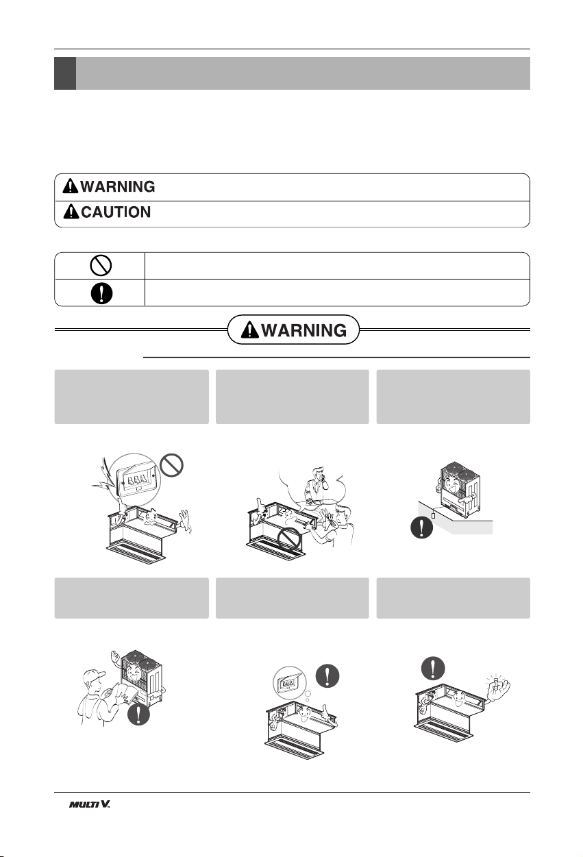
■ Installation
Do not use a defective or underrated circuit breaker. Use this
appliance on a dedicated circuit.
• There is risk of fire or electric shock.
For electrical work, contact the
dealer, seller, a qualified electrician, or an Authorized Service
Center.
• Do not disassemble or repair the
product. There is risk of fire or electric shock.
Always ground the product.
• There is risk of fire or electric shock.
Install the panel and the cover
of control box securely.
• There is risk of fire or electric shock.
Always install a dedicated circuit and breaker.
• Improper wiring or installation may
cause fire or electric shock.
Use the correctly rated breaker
or fuse.
• There is risk of fire or electric shock.

Installation Manual 5
ENGLISH
Safety Precautions
■ Operation
Do not modify or extend the
power cable.
• There is risk of fire or electric shock.
Do not let the air conditioner
run for a long time when the
humidity is very high and a door
or a window is left open.
• Moisture may condense and wet or
damage furniture.
Be cautious when unpacking
and installing the product.
• Sharp edges could cause injury. Be
especially careful of the case edges
and the fins on the condenser and
evaporator.
For installation, always contact
the dealer or an Authorized
Service Center.
• There is risk of fire, electric shock,
explosion, or injury.
Do not install the product on a
defective installation stand.
• It may cause injury, accident, or
damage to the product.
Be sure the installation area
does not deteriorate with age.
• If the base collapses, the air conditioner could fall with it, causing property damage, product failure, and
personal injury.
Do not store or use flammable gas or combustibles near the product.
• There is risk of fire or failure of product.
Gasolin
6 Indoor Unit6 Indoor Unit
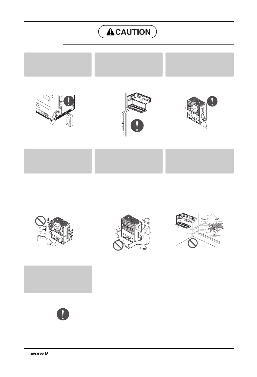
Safety Precautions
Always check for gas (refrigerant) leakage after installation or
repair of product.
• Low refrigerant levels may cause
failure of product.
Install the drain hose to ensure
that water is drained away properly.
• A bad connection may cause water
leakage.
Keep level even when installing
the product.
• To avoid vibration or water leakage.
Do not install the product where
the noise or hot air from the outdoor unit could damage the
neighborhoods.
• It may cause a problem for your
neighbors.
Use two or more people to lift
and transport the product.
• Avoid personal injury.
Do not install the product where
it will be exposed to sea wind
(salt spray) directly.
• It may cause corrosion on the product.
Corrosion, particularly on the condenser and evaporator fins, could
cause product malfunction or inefficient
operation.
■ Installation
If you eat the liquid from the
batteries, brush your teeth and
see doctor. Do not use the
remote if the batteries have
leaked.
• The chemicals in batteries could
cause burns or other health
hazards.
90˚
Installation Manual 7
ENGLISH
Introduction
Introduction
Wired Remote Controller
Wired Remote Controller
Re
m
o
te
Co
nt
ro
lle
r
T
E
M
P
R
e
mo
te C
ontro
ller
T
E
M
P
This symbol alerts you to the risk of electric shock.
This symbol alerts you to hazards that could cause harm to the
air conditioner.
This symbol indicates special notes.
NOTICE
Symbols Used in this Manual
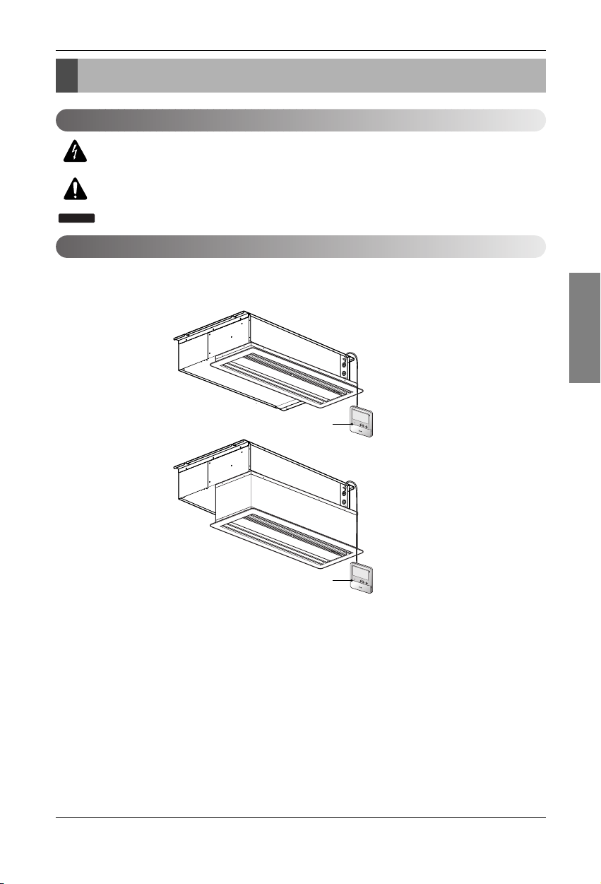
Features
Built-in Duct type
Suction Grille
Suction Grille + Suction Canvas

8 Indoor Unit8 Indoor Unit
Installation
Installation
Indoor unit
Install the air conditioner in the location that satisfies the following conditions.
• The place shall easily bear a load exceeding four times the
indoor unit’s weight.
• The place shall be able to inspect the unit as the figure.
• The place where the unit shall be leveled.
• The place shall easily connect with the outdoor unit.
• The place where the unit is not affected by an electrical
noise.
• The place where air circulation in the room will be good .
• There should not be any heat source or steam near the
unit
Confirm the positional relationship between the unit and
suspension bolts.
• Installation the ceiling opening to clean the filter or service
under the product.
Selection of the best location
A(Min)
B(Min)
Ceiling
Service Space
A
B
• Refer to Suction grille and Suction canvas installation
manual for detail installation of Built-in duct type
270(7-5/8)
or more
520(7-5/8)
or more
Inspection hole
(600(23-5/8) x 600(23-5/8))
Control box
600
(23-5/8)
600
(23-5/8)
Top view
[Unit: mm(inch)]
Airflow
[Unit: mm(inch)]
Built-in Duct type
Chassis A B
B3 600(23-5/8) 900(35-7/16)
B4 600(23-5/8) 1100(43-5/16)
[Unit: mm(inch)]
Installation Manual 9
ENGLISH
Installation
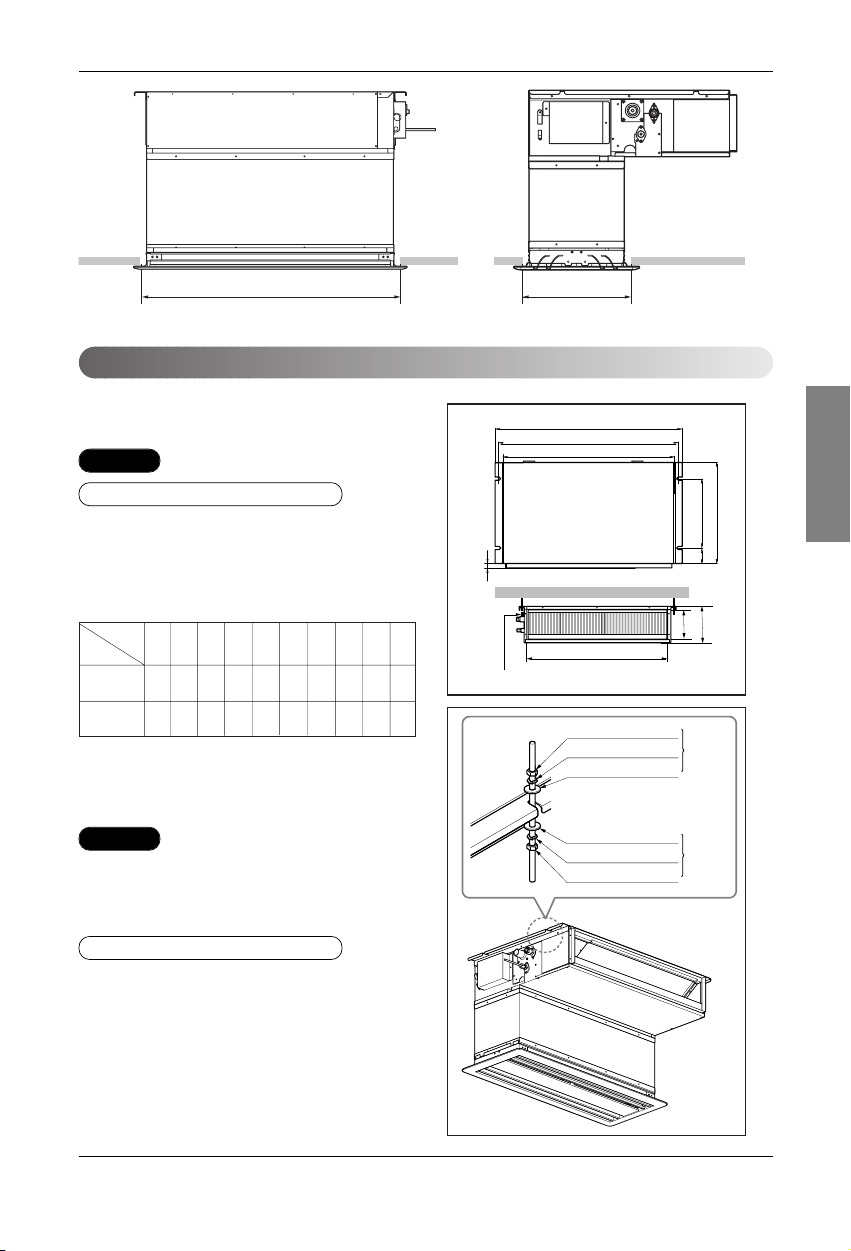
Ceiling dimension and hanging bolt location
Installation of Unit
Install the unit above the ceiling correctly.
• Apply a joint-canvas between the unit and duct to absorb
unnecessary vibration.
• Apply a filter Accessory at air return hole.
• Install the unit leaning to a drainage hole side as a figure
for easy water drainage.
• A place where the unit will be leveled and that can support
the weight of the unit.
• A place where the unit can withstand its vibration.
• A place where service can be easily performed.
CASE 1
POSITION OF SUSPENSION BOLT
CE
G
D
A
J
B
M10 Nut
M10 SP. washer
M10 washer
X 4
X 4
(Local
supply)
X 4
M10 Nut
M10 SP. washer
M10 washer
X 4
X 4
(Local
supply)
X 4
I
F
H
Drainage hole
Drain Pump use
CASE 2
POSITION OF CONSOLE BOLT
B3/B4: 295mm(11-3/5 inch)
(Ceiling opening)
B4: 1,118mm(44 inch)
B3: 840mm(33-1/16 inch)
(Ceiling opening)
[Unit: mm(inch)]
B3
B4
Dimension
Chassis
ABCDEFGHI J
850 900 383 575 93 190 21 795 163 820
(33-7/16) (35-7/16) 383(15) (22-5/8) (3-11/16) (7-7/16) (7/8) (31-5/16) (6-7/16) (32-5/16)
1130 1180 383 575 93 190 21 1065 163 1100
(44-7/16) (46-7/16) 383(15) (22-5/8) (3-11/16) (7-7/16) (7/8) (41-15/16) (6-7/16) (43-5/16)
 Loading...