

WIRELESS 433 MHz WEATHER STATION
Instruction Manual
INTRODUCTION:
Congratulations on purchasing this fancy Cubic Weather station
wireless 433MHz transmission. It not only displays the indoor
temperature and humidity but also receives the outdoor temperature.
It is further acting as a DCF-77 radio controlled clock and gives
colour-changing backlight.
With the totally 15 different weather forecast icons featured by
"weather man", users can easily observe the forecast weather
condition and will no longer worry the sudden weath er change. This
innovative product is ideal for use in the home or office.
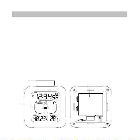
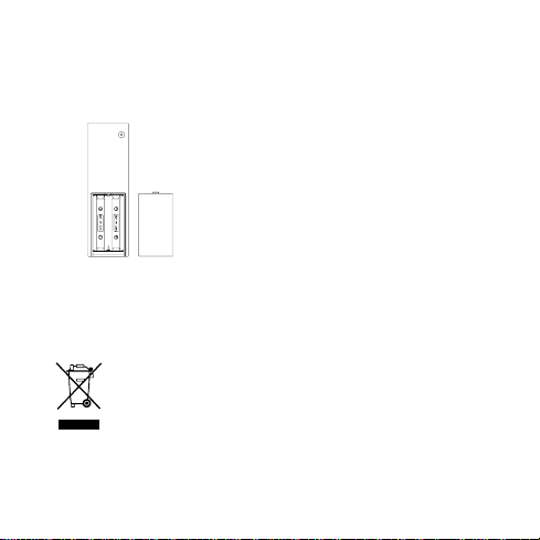
THE WEATHER STATION
Function
LCD
Display
Keys
36
Battery
compartment
cover

FEATURES
• DCF-77 Radio-controlled time and date
• 12/24 hour display
• Hour, minute and second time display
• Calendar (weekday, date and month)
• Time zone option ±12 hours
• Weather forecasting with 15 easy-to-read weather forecast
signs featured by weather man
• Displays indoor temperature & humidity
• Display outdoor temperature
• Temperature display in degrees Celsius (°C) or Fahrenheit
(°F) selectable
• Colour-changing EL backlight (with permanent backlight
ON/OFF function, and the case of the weather station will also
be illuminated when the backlight is ON).
Alarm with snooze function •
• LCD contrast setting
• Table standing
37
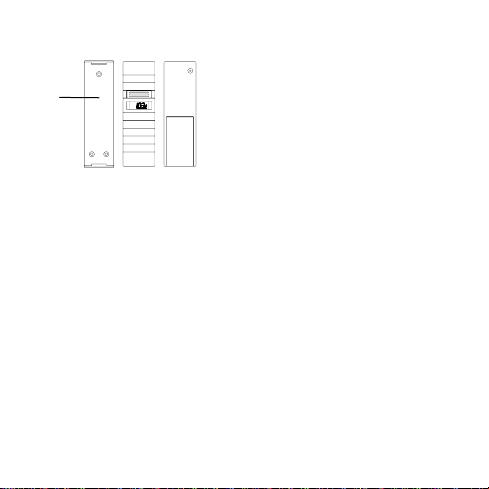
TEMPERATURE TRANSMITTER:
Holder
ETTING UP
S
1. First, inse
2.
3. After inserting the batteries into the transmitter, the weather
rt 4 x AAA, IEC LR3, 1.5V batteries into the weather
station. Once the batteries are in place, all segments of th e
LCD will light up briefly. Then the indoor temperature, the
weather man icon and the time as 0:00, will be displayed. If
the indoor temperature is not displayed after a few seconds,
remove the batteries and wait for at least 30 seconds before
reinserting them. Once the indoor data is displayed proceed to
step 2.
Within 45 seconds of activating the Weather station, place 2 x
AA, IEC LR6, 1.5V batteries into the transmitter.
station will start receiving data from the transmitter. The
remote temperature will then be displayed on the station. If
this does not happen after 2 minutes, the batteries will nee d to
be removed from both units and reset from step 1.
emote transmission of outdoor
• R
temperature to Weather station by
433 MHz
•
Shower pro-of casing
• Wall mounting case (M
a sheltered place. Avoid direct
rain and sunshine)
ounting at
38

4.
When the transmitter is set up, there is a testing period. Then
DCF-77 time code reception is automatically starte
the clock is activated. This takes typically between 3 - 5
minutes in good conditions. This time period is an excellent
opportunity to locate the transmitter in suitable location
outdoors. In order to ensure sufficient 433 MHz transmission
however, this should under good conditions be no more than
25 meters from where the Weather station will be finally
positioned (see notes on “POSITIONING THE OUTDOOR
TRANSMITTER” and “433 MHZ RECEPTION”).
5.
If after 10 minutes the DCF time has not been received, use
the MODE/ MIN key to manually enter a time
initially. The unit will still try and receive the time signal
regularly despite it being manually set. When it does receive
the signal, it will change the manually set time into the
received time.
Note:
d the total timeShoul of inserting the batteries into the transmitter
nger than 1-1/2 minutes from the time of inserting the
take lo
batteries into the weather station then temperature reception
problems may occur. If the temperature is not being received , then
see "433 MHZ RECEPTION", before resetting the units.
In the event of changing batteries to the transmitter, t
ation needs to be reset. (See Resetting the weather station)
st
d just after
(and date)
he weather
39
RESETTING THE WEATHER STATION
To reset the Weather station to the factory default setting or in case
a malfunction or changing batteries to transmitter, please remove
of
all batteries from the unit and unplug the AC/D
power source. Wait at least for 3 minutes before powering up the
Weather station again.
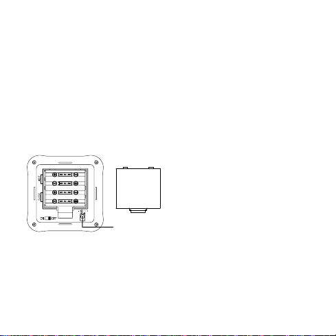
TO INSTALL AND REPLACE BATTERIES INTO THE WEATHER STATION
he Weather station uses 4 x AAA, IEC LR3, 1.5V batteries (Two no.
T
of batteries for the station functioning and two for the backlight). To
install and r
eplace the batteries, please follow the steps below:
1. Insert finger or other solid
2.
Socket for
adaptor
In addition or instead of inse batteries, the AC apter can be
used:
1. Connect the power adapter t a wall socket
3. Replace compartment
rting ad
o
C adapter from any
object in the space at the
bottom centre of the ba
compartment and lift up to
remove the cover.
Insert batteries observing
the correct polarity (see
marking).
ttery
cover.
40
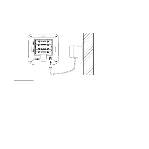
2. Insert the adapter into the jack at the bottom of the station
3. The Weather station will now start receiving the DCF time
signal. After approximately 3 to 5 minutes, t
be displayed (Also see "SETTING UP" below) .
Important!
Use only the adapter provided with the W eather station and make
re that your household voltage is appropriate to the working
su
voltage of the tra
damaged.
POWER SUPPLIED BY BATTERIES AND AC/DC ADAPTER
If the Weat
dapter is subsequently used for extended period of ti me, the main
a
power source of the Weather station will switch to AC/DC p o
The batteries will then act as a backup power source in case of
power failure.
nsformer. Otherwise your Weather station may be
her station is first powered by batteries and the power
he DCF time will
wer.
41
TO INSTALL AND REPLACE BATTERIES IN THE
TEMPERATURE TRANSMITTER
The Temperature Transmitter uses 2 x AA, IEC, LR6, 1.5V batteries.
To install and replace the batteries, please follow the steps below:
BATTERY CHANGE:
It is recommended to replace the batteries in all units regularly to
ensure optimum accuracy of these units (Battery life See
Specifications below).
Please participate in the preservation of the
environment
depot.
1. Remo
2. Insert the batteries, observing the
3. Replace the battery
. Return used batteries to an authorised
ve the cover.
correct polarity (see marking).
cover on the unit.
42

D
CF-77 RADIO CONTROLLED TIME
he time base for th
T
operated by the Physikalisch Te
Braunschweig which has a time deviation of less than one sec ond in
one million years. The time is coded and transmitted from
Mainflingen near Frankfurt via frequency signal DCF-77 ( 77.5 kHz)
and has a transmitting range of approximately 1,500 km. Your radiocontrolled Weather station receives this signal and converts it to
show the precise time in summer or wintertime.
The quality of the reception depends greatly on the geographic
location. In normal cases, there should be no reception pr oblems
within a 1500km radius of Frankfurt.
Once the outdoor reception test period is completed, the D CF tower
con in the time display will start flashi
has detected that there is a radio signal present and is trying to
receive it. When the time code is received, the DCF tower becomes
permanently lit and the time will be displayed.
If the tower icon flashes, but does not set the time or the DCF tower
does not appear at all, then please take note of the following:
• Recommended distance to any interfering sources like
computer monitors or TV sets is a minimum of 1.5 - 2 metres.
• W ithin ferro-concrete rooms (base ments, superstructures ), the
received signal is naturally weakened. In extreme cases,
please place the unit close to a window and/or point its front o r
back towards the Frankfurt transmitter.
e radio controlled time is a Cesium Atomic Clock
chnische Bundesanstalt
ing. This indicates that the unit
43
Durin
g nighttime, the atmospheric disturbances are usually less
sever cases. A single daily
e and reception is possible in most
reception is adequate to keep the accuracy deviation below 1
second.
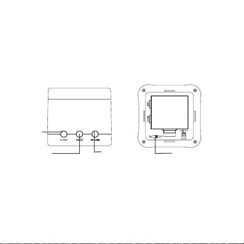
N KEYS
FUNCTIO
here are three function keys at the top of the weather station and
T
one at the back.
A OUR
L/H
key
Light ON/OFF
key
Ba
ck
Top
MODE/MIN
key
44
SNO ey
OZE k
S•NOOZE key
Press to initiate the snooze function when the alarm is
• Press to confirm the manual setting in the different settin g
sound
modes
ing.

• Press to activate the EL back-light
AL R key
/HOU
P
• ress and hold to advance to the alarm time setting
• Press t
• Press to set the hour in time setting mode
• Press to set the date in calendar setting
• Press to activate the EL back-light
• Press to stop the alarm and snooze
DE/M
MO IN key
•
• Press to
• Press to set the minute in time setting mode
• Press to set the month and year in calendar se
• Press to toggle between various display for "
•
• the alarm and snooze
HT O
LIG N/OFF key
•
o set the hour in alarm setting mode
Press and hold to advance to the manual setting
set the minute in alarm setting mode
tting mode
"day & weekday", "indoor temperature & humidity" and
"alarm time"
Press to activate the EL back-light
Press to stop
To Switch On / Off the permanent mode of colour-chan ging
LED backlig
ht
day & month",
45

LCD SCREEN AND SETTINGS:
Radio controlled time
ception On icon
re
Weather
Forecast icon
eat
(W
her man)
"indoor temperature
and humidity",
"preset alarm time" or
"calendar display"
For better distinctness t
ection 1 - TIME
S
• In normal mode, display the current time.
Time
he LCD screen is split into 4 sections:
Alarm icon
Weather
Tendency icon
Outdoor
Temperature
46

Section 2 - WEATHER ICON (FEATURED BY WEATHER MAN)
• Display of the weather to be expected in form of 15 fancy
weather symbols (featured by Weather man) which change
their appearance depending on the air pressure development
(past air pressure change) and the current outdoor
temperature.
• ather tendency indicator
Display the we
ection 3 - INDOOR DATA/ PRESET ALARM TIME/ CALENDAR
S
• Display the "day & month", "day & weekday", "indoor
temperature & humidity" or "alarm time"
ection 4 - OUTDOOR TEMPERATURE
S
• Display the outdoor temperature.
ANUAL SETTING
M
LCD contrast level
After pressing and ho
the manual setting mode is activated. Then The LCD contrast can be
set:
lding the MODE/MIN key for about 3 seconds,
flashing
47

1. The contrast level will be flashing. Press the MODE/MIN key
to adjust the contrast level 0 to 7 (default: 5).
2. Press the SNOOZE ke y to confirm and enter the Time zone
setting mode.
Time zone setting
The time zone default of the Weather station is “0”. T o set a different
time zone:
1. The current time zone value at the bottom of the LCD display
starts flashing.
2. Press and release MODE/MIN key to adjust the time zone.
The range runs from 0, -1, -2 to -12, then 12, 11, 10 to 0, i n
consecutive 1-hour intervals.
3. Confirm with the SNOOZE key and enter the Manual time
setting.
Manual time setting
In case the Weather station cannot detect the DCF-signal (for
example due to disturbances, transmitting distance, etc.), the time
can be manually set. The station will then work as a normal Quartz
flashing
48

clock.
Hours
(flashing)
1. The hour and the minute digits will start flashing.
2. Use the AL/HOUR key to set the hour; MODE/MIN key to set
the minute.
3. Confirm with the SNOOZE key and enter the Calendar
setting.
Note:
The unit will still try and receive the time signal regularl y despite it
being manually set. When it does receive the signal, it will change
the manually set time into the received time.
Calendar setting
The date default of the Weather station is 1. 1. in the year 2005 .
Once the radio-controlled time signals are received, the date is
automatically updated. However, if the signals are not received, the
date can also be set manually.
1. The year starts flashing.
Minutes
(flashing)
49

2. Use the MOD E/MIN key to set the year (between year 2003-
2029).
3. Press the SNOOZE key to confirm and to enter the month and
day setting. The month and day digits will start flashing.
4. Use the AL/HOUR key to set the da y and MODE/MIN key to
set the month.
5. Press the SNOOZE key again to confirm and to enter the
12/24 hour time format setting.
"Day. Month." (for 24h time display)
"Month. Day." (for 12h time display)
Year
50

12/24 hour time format setting
1. The time format digit starts flashing. Press the MODE/ MIN ke y
to select the 12-hour or 24-hour time format.
2. Press the SNOOZE key again to confirm and to enter the
Temperature unit (°C/ °F) setting.
Temperature unit (°C/ °F) setting
1. The temperature unit digit starts flashing. Press the
MODE/MIN key to select the unit °C or °F.
2. Press the SNOOZE key again to confirm and to enter the
Daylight saving time setting.
flashing
flashing
51

Daylight saving time setting
Note:
The function of daylight saving time on/off is only applicable to
specific area in United states using WWVB time sources. It is not
applicable for DCF-77 signal in European countries.
• User may skip doing this part of setting for this European
version weather station (-press the SNOOZE key to exit the
setting mode and go back to the normal display). Setting of
“dST On” or “dST Off” will have no effects on the reception
time.
TIME ALARM
Setting the alarm
1. Press and hold “AL/HOUR” button for about three second s
until the alarm time is flashing.
52

Alarm time
(flashing)
2. Press and release “AL/HOUR” to advance the hour, an d
“MODE/MIN” to advance the minute. The time will display
in 24-hour format.
3. Press the SNOOZE key to confirm. T he alarm is now set
and activated.
Activating / Deactivating the alarm
1. After entering the alarm-setting mode, the alarm is
activated.
2. To toggle between activating and deactivating the alarm,
press the “AL/HOUR” button briefly. Alarm-on icon, “(((•)))”
will be displayed next to the time display when the alarm is
activated.
Alarm icon
flashing
53

Turning alarm off (while sounding)
–
–
–
1. While the alarm is sounding, press and release the
SNOOZE bar to disable the alarm for 10 minutes. (Af ter the
SNOOZE bar is pressed, the alarm icon will keep flashing.
After 10 min, the alarm will sound again.)
2. To disable the alarm, press and r elease the AL/HOUR or
MODE/MIN button.
WEATHER FORECAST AND TENDENCY:
The weather forecast icons (Weather man):
One of the 15 different weather icons (featured by Weather man with
different clothing) is displayed in the centre of LCD, which i ndicates
the different forecast weather condition due to air pressure level
(Sunny, Sunny + Cloudy or Rainy) and the current outdoor
temperature:
Sunny
≥ 26°C
19
25.9°C
10
18.9°C
0
9.9°C
< 0°C
54

–
–
–
–
–
–
Sunny +
Cloudy
Rainy
For every sudden or significant change in the air pressure, the
weather icons will update accordingly to represent the change in
weather. If the icons do not change, then it means either the air
pressure has not changed or the change has been too slo w for the
≥ 26°C
≥ 26°C
19
25.9°C
25.9°C
19
10
18.9°C
10
18.9°C
0
9.9°C
0
9.9°C
< 0°C
< 0°C
55

Weather station to register. However, if the icon displayed is a sun or
raining cloud, there will be no change of icon if the weather gets any
better (with sunny icon) or worse (with rainy icon) since the icons are
already at their extremes.
The icons displayed forecasts the weather in terms of getting better
or worse and not necessarily sunny or rainy as each ico n indicates.
For example, if the current weather is cloudy and the rain y icon is
displayed, it does not mean that the product is faulty because it is
not raining. It simply means that the air pressure has dropped and
the weather is expected to get worse but not necessarily rainy.
Note:
After setting up, readings for weather forecasts should be
disregarded for the next 12-24 hours. This will allow sufficient time
for the Weather station to collect air pressure data at a constant
altitude and therefore result in a more accurate forecast.
Common to weather forecasting, absolute accuracy cannot be
guaranteed. The weather forecasting feature is estimated to have an
accuracy level of about 75% due to the varying areas the Weather
station has been designed for use in. In areas that experience
sudden changes in weather (for example from sunny to rain), the
Weather station will be more accurate compared to use in areas
where the weather is stagnant most of the time (for example mostly
sunny).
56

If the Weather station is moved to another location significantly
higher or lower than its initial standing point (for e xample from the
ground floor to the upper floors of a house), remove the batteries
and re-insert them after about 30 seconds. By doing this, the
Weather station will not mistake the new location as being a p ossibl e
change in air-pressure when really it is due to the slight c hange of
altitude. Again, disregard weather forecasts for the next 12 to 24
hours as this will allow time for operation at a constant altitude.
THE WEATHER TENDENCY INDICATOR
Working together with the weather icons are the weather ten dency
indicators (the upward and downward arrow located near the
Weather man). When the indicator points upwards, it means that the
air-pressure is increasing and the weather is expected to impro ve,
but when indicator points downwards, the air-pressure is dropping
and the weather is expected to become worse.
Therefore, user may see how the weather has changed and is
expected to change. For example, if the indicator is pointing
downwards together with cloudy icons, it means that the last
noticeable change in the weather was when it was sunny (the sunny
icon only). Therefore, the next change in the weather will be the
cloudy icons since the indicator is pointing downwards.
Note:
Once the weather tendency indicator has registered a change in air
pressure, it will remain permanently visualized on the LCD.
57

TOGGLE BETWEEN THE DISPLAY OF INDOOR TEMPERATURE/
HUMIDITY, PRESET ALARM TI ME AND CALENDAR
By pressing shortly the MODE/MIN key, you will toggle between the
following displays:
1. Indoor temperature and humidity;
2. Preset alarm time;
3. Month and day
3. Day and weekday;
COLOUR-CHANGING BACKLIGHT
1. The Weather station has a colour-changing EL backlight
designed for night-viewing. This will light up for about 10
seconds when any button is pressed. The case of the weather
station will also be illuminated when the backlight is ON.
58

2. When the backlight key is s witch "ON ", t h e EL bac klight will be
turned on permanently.
Note: If batteries are used, the permanent switching on the backlight
may drain off the batteries faster.
3. The EL backlight will be turned on when the alarm time is
reached.
433MHz RECEPTION
If the outdoor temperature data are not being received within three
minutes after setting up (or “- -. -” is shown in the outdoor
temperature section of the Weather station after 3 failed atte mpts
during normal operation), please check the following points:
1. The distance of the Weather station or t ransmitter should be
at least 2 metres away from any interfering sources such as
computer monitors or TV sets.
2. Avoid placing the transmitter onto or in the immediate
proximity of metal window frames.
3. Using other electrical products such as headphones or
speakers operating on the 433MHz-signal frequency may
prevent correct signal transmission or reception. Neighbours
using electrical devices operating on the 433MHz-signal
frequency can also cause interferences.
Note:
59

When the 433MHz signal is received correctly, do not re-open the
battery cover of either the transmitter or Weather station, as the
batteries may spring free from the contacts and force a false reset.
Should this happen accidentally then reset all units (see “Setting
up” above) otherwise transmission problems may occur.
The transmission range is around 25 metres from the Temp erature
transmitter to the Weather station in open space). However, this
depends on the surrounding environment and interferenc e levels. If
no reception is possible despite the observation of these factors, all
system units have to be reset (see “Setting up” above).
POSITIONING THE WEATHER STATION:
Free standing
The weather station can be placed onto any flat surface.
60

POSITIONING THE TEMPERATURE TRANSMITTER:
To wall mount:
Note:
Before permanently fixing the transmitter wall base, place all units in
the desired locations to check that the outdoor tempe rature reading
is receivable. In event that the signal is not received, relo cate the
The Transmitter is supplied with a holder
that may be attached to a wall with the
two screws supplied. The Transmitter
can also be position on a flat surface by
securing the stand to the bottom to the
Transmitter.
1. Secure the bracket onto a desired wall
using the screws and plastic anchors.
2. Clip the remote temperature sensor onto
the bracket.
61

transmitters or move them slightly as this may help the signal
reception.
CARE AND MAINTENANCE:
• Extreme temperat ures, vibration and shock should be avoide d
as these may cause damage to the units and gi ve inaccurate
forecasts and readings.
• W hen cleaning the d isplay and casings, use a soft da mp cloth
only. Do not use solvents or scouring agents as they may
mark the LCD and casings.
• Do not submerge the units in water.
• Immediately remove all low powered batteries to avoid
leakage and damage. Replace only with new batteries of the
recommended type.
• Do not make any repair attempts to the units. Retur n it to their
original point of purchase for repair by a qualified engineer.
Opening and tampering with the units may invalidate their
guarantee.
• Do not expose the units to extreme and sudden temperature
changes, this may lead to rapid changes in forecasts and
readings and thereby reduce their accuracy.
SPECIFICATIONS:
Temperature measuring range:
Indoor : -9.9ºC to +36.9ºC with 0.1°C resolution
(“OF.L” displayed if outside this range)
Indoor humidity range : 1% to 99% with 1% resolution
62

(Display “- -“ if outside this range)
Indoor temperature checking intervals : Every 15 seconds
Indoor humidity checking intervals : Every 20 seconds
Outdoor : -29.9ºC to +69.9ºC with 0.1°C resolution
(“OF.L” displayed if outside this range)
Outdoor temperature checking intervals : Every 5 minutes
Power consumption:
Weather station : 4 x AAA, IEC LR3, 1.5V
Or
AC adapter : INPUT 230V AC 50Hz;
OUTPUT: DC 3.4V (use the
provided AC/DC adapter only)
Outdoor transmitter : 2 x AA, IEC LR6, 1.5V
Battery life cycle (Alkaline batteries recommended)
Weather Station : Approximately 12 months
Outdoor transmitter : Approximatel y 24 months
Dimensions (L x W x H):
Weather station : 90 x 81 x 90 mm
Outdoor transmitter : 39 x 21 x 128 mm
63

LIABILITY DISCLAIMER
• The electrical and electronic wastes contain hazardous
substances. Disposal of electronic waste in wild country and/or
in unauthorized grounds strongly damages the environment.
• Please contact your local or/and regional authorities to retrie ve
the addresses of legal dumping grounds with selective
collection.
• All electronic instruments must from now on be recycled. User
shall take an active part in the reuse, recycling and recovery of
the electrical and electronic waste.
• The unrestricted disposal of electronic waste may do ha rm on
public health and the quality of environment.
• As stated on the gift box and labeled on the product, reading
the “User manual” is highly recommended for the benefit of the
user. This product must however not be thrown in general
rubbish collection points.
• The manufacturer and supplier cannot accept any
responsibility for any incorrect readings and any
consequences that occur should an inaccurate reading take
place.
• This product is designed for use in the home only as indic ation
of the temperature.
• This product is not to be used for medical purposes or for
public information.
• The specifications of this product may change without prior
notice.
64

• This product is not a toy. Keep out of the reach of children.
• No part of this manual may be reproduced without written
authorization of the manufacturer.
R&TTE DIRECTIVE 1999/5/EC
Summary of the Declaration of Conformity : We hereby declare that
this wireless transmission device does comply with the essential
requirements of R&TTE Directive 1999/5/EC.
65
 Loading...