

TouchScreen
Wireless Weather Station
WS 2-550
Operating Instructions
La Crosse Technology
1

Contents
1. General aspects and functioning, Quick Overview ...................................................... 4
2. Preparatory work ...................................................................................................................... 8
2.1. Preparing the weather station .............................................................................................. 8
Connecting to the mains ........................................................................................................ 8
Inserting batteries .................................................................................................................... 9
Installing/Mounting .................................................................................................................. 9
Start-up .......................................................................................................................................13
2.2. Combi-sensor TX 550 ............................................................................................................13
3. Operations
3.1. Log in/delete external sensors ...........................................................................................16
3.2. Operations ................................................................................................................................ 18
3.3. Conguration ............................................................................................................................20
3.3.1. "SENSOR" menu, Login/ Delete sensors ..........................................................................20
3.3.2. "TIME/DATE" menu, Set the time and date.....................................................................20
3.3.3. "UNITS" menu, Set the display units .................................................................................21
3.3.4. "POSITION" menu, Set position ..........................................................................................22
3.3.5. "TIMEZONE" menu, Set time zone .....................................................................................23
3.3.6. "LIGHTING” menu, time setting for the background lighting and .............................
regulating the brightness of the lightening ..................................................................23
3.3.7. "SYSTEM" menu, System settings ......................................................................................24
"BEEP", Activate/ deactivate beep ......................................................................................24
"DST", Activate/ deactivate the daylight saving time switching .............................25
"INTERVALL", Set the recording interval for the datalogger .....................................25
"ALTITUDE", Adjust the location height above sea level ............................................25
"RAIN CAL", Enter the comparison value for the rain sensor ....................................26
"SUN CAL", Congure brightness threshold value for duration of sunshine ......26
3.3.8. "CLEANING" menu, Cleaning mode ..................................................................................27
3.3.9. "LIVE MODE" menu, call up the current weather data ow .....................................28
3.4. Other Functions and Displays .............................................................................................29
Display moon phases .............................................................................................................29
Oscar Outlook ...........................................................................................................................29
Weather forecast ......................................................................................................................29
Wind symbol display ..............................................................................................................29
Immediate Rain Display ........................................................................................................30
Comfort Indicator ....................................................................................................................30
History .........................................................................................................................................30
Data memory ...........................................................................................................................30
Data transfer to the combi-sensor "WAIT FOR TRANSMISSION" .............................30
Temperature trend display ...................................................................................................30
Sensor Status Display .............................................................................................................31
Warning against turbulent weather .................................................................................31
Frost warning ............................................................................................................................31
................................................................................................................................16
2

4. Changing the batteries .........................................................................................................31
5. Troubleshooting .....................................................................................................................32
6. Range ..........................................................................................................................................34
7. Instructions for Maintenance and Care ..........................................................................34
7.1. Cleaning the rain quantity sensor .....................................................................................35
7.2. Setting the rain sensor ...........................................................................................................36
8. Technical specications ........................................................................................................37
9. Optional PC connection for third party software ........................................................38
10. Appendix ...................................................................................................................................39
11. Proper use, exclusion of warranty,
Safety Instructions .................................................................................................................40
12. Wireless Technology BidCoS ...............................................................................................41
13. FCC Information .......................................................................................................................42
Appendix A: Menu Overview WS 2-550 .........................................................................43
Appendix B: Table of latitude/longitude of French counties ...................................44
Appendix C: Table of time zone dierence from UTC .................................................62
1. English Edition 3/2007
Documentation © 2007 La Crosse Technology
All rights reserved. No parts of this manual may be reproduced or processed in any form using electronic, mechanical or
chemical processes in part or in full without the prior explicit written permission of the publisher.
It is quite possible that this manual has printing errors or defects.
The details provided in this manual are checked regularly and corrections are done in the next edition. We do not assume
any liability for technical or printing errors.
All registered trade marks and copyrights are acknowledged. Printed in Hong Kong.
We reserve the right to make changes due to technical advancements without prior notice.
74889 Y2007 V1.0
3

1. General aspects and Function
The TouchScreen Wireless Weather Station WS 2-550 is a high-quality, highly comfortable
universal weather measurement system that can record, process and display data from
a maximum of 8 (currently not available) additional wireless temperature and humidity
sensors as well as a combi-sensor up to a distance of 400 ft. (outdoor range).
The combination sensor TX 550 belonging to the weather station is meant for outdoor
use and captures the following:
Temperature, humidity, direction of wind, wind velocity, set in of rain, rain quantity
and duration of sunshine.
The weather sensors for inside temperature, indoor humidity and air pressure are
already located inside the weather station; hence no external sensor is required for
these measurements.
The operating concept is the most excellent feature of the weather station. It does
not have any traditional operating elements; it is operated only with the help of a
highly sensitive TouchScreen and simple menu structures. Even the weather sensors can easily log into the system.
Weather data from the combi-sensor can be queried in real time; in “live mode”
touching the respective display field triggers a data query (bi-directional wireless
technology). Hence, the latest data is always available. Further, the combi-sensor
can also be prompted in "live mode" to send its measurement data for 20 seconds
at 2 seconds intervals. You can track in real time the wind direction and the wind
velocity for 20 seconds. The display can be illuminated permanently or with time
controls; thus the display is legible under almost all light conditions. The glass foot
and the transparent design frame of the device are also illuminated.
As the weather station has a large internal memory it is best suited for observation
over long periods - a total of 3000 records can be stored in the internal memory.
Please read this Operating Instructions manual carefully and in full to avoid
functional disturbances and wrong operations. Please store this manual
for future reference.
Please follow the assembling and calibration instructions for the measure ment recorders.
4

Overview of the display and operating options of WS 2-550 :
Display the inside temperature and humidity
- Switch to displaying the dewpoint
- Save the minimum and maximum temperature with time/date of occurrence
- Save the minimum and maximum humidity with time/date of occurrence
- Comfort zone indicator
- Graphical trend display of the last 24 h (only for temperature)
Display’s outdoor temperature/humidity from Combi Sensor.
- Can be switched: Display the dewpoint or wind-chill temperature
- Save the minimum and maximum temperature with time/date of occurrence
- Save the minimum and maximum humidity with time/date of occurrence
- Graphical trend display of the last 24 h (only for temperature)
- Frost warning (in “Oscar Outlook” display)
Display the wind velocity with wind direction and uctuation range
- Units for selection: : km/h, m/s, mph
- Save the maximum wind intensity with time/date
- Display wind direction with fluctuation range as wind rose and in numeric format
- Wind-sack symbol for prominent signaling of various wind intensities
Display the rainfall quantity in mm, inch or l/m2 for:
-
Total quantity since the last reset / last hour / current hour / last 24 h / current 24 h
(storage for hour: always at xx:30 hours; storage for day: always at 7:30 a. m.)
- Save the maximum quantity per hour and per day
- Additional display when it starts raining (Immediate rain display)
Display the air pressure progress/ air pressure trend display:
- Graphical display of the progress in the last 24 h
- Display the air pressure trend in 5 stages: heavily increasing, increasing, uniform,
decreasing, heavily decreasing
Display symbols of the weather forecast: rainy, cloudy, bright, sunny
Weather display "Oscar Outlook"
Similar to the almost forgotten weather "house" where a person came out of the door
with an umbrella if the weather was bad and wore light clothes if it was good, WS 2-550
has "Oscar Outlook".
The behavior of this character is based on various weather factors; hence it is immediately possible to know the type of clothing one would need outdoors.
Not only the current measured values for outside temperature, humidity, wind and
rain are evaluated for this display.
5

The weather forecast also plays an equally important role. So "Oscar Outlook" has
dierent displays and clothing depending on the weather situation.
You will nd a detailed description of the evaluation criteria in chapter 3.4 of this
Operating Instructions manual.
Display the sunrise and sunset time
- Calculation can be done in the latitude range of -60° to +60˚ N depending on the
location data that is to be entered.
Moon phase display
- Display the current moon phase: New moon, waxing moon, waning moon
Display the total duration of sunshine or of the current day
- Save the minimum and maximum duration per day with time/date of occurrence
- Sun symbol if there is sunshine
Data logging function
- Data logger can collect maximum 3000 records at programmable intervals; these
can then be read via an USB interface using. Optional third party software located
at www.weather-display.com (Note: manufacturer does not support software)
- If the data logger memory is full, the system displays a timely message prompting
you to download the data.
Miscellaneous
- Very simple set up menu
- An acknowledgement beep can be switched on / o as required
-
Depending on the need, the device can be installed on the table or mounted on the
wall
- Switching time of the display lighting can be programmed
All important weather information appears simultaneously on the display so that it
is not necessary to operate the device to capture the data.
Multiple basic units can be operated simultaneously; hence the data of the sensors
can be simultaneously displayed at multiple locations.
The external sensor system of WS 2-550 works exclusively on wireless data transfer. You
can thus install or mount the sensors at a maximum distance of 400 ft. (depending on the
local conditions, see section "Range") from the base station.
2. Preparatory work
6
Quick overview of the display elds
2 3
26
25
24
23
22
4
51
6
7
8
9
21
20
19
18
10
11
12
13
14
151617
1. Current indoor temperature with temperature trend
2. Displays the current direction of the wind (main wind direction)
3. Display the uctuation range when wind direction is changing
4. Displays the speed of the wind
5. Current humidity of the selected outdoor sensor
6. Current temperature of the selected outdoor sensor with temperature trend and recep
tion display
7. Displays the currently selected outdoor sensor (no display if you select TX 550 US)
8. Moon phase display
9. Displays the weather forecast (sunny, bright, cloudy, rainy)
10. Animated multiple weather display "Oscar Outlook"
11. Displays speed of wind (mild, medium, strong)
12. Warning against turbulent weather
13. Frost warning
14. Menu bar
15. Trend display for air pressure: strongly increasing, slightly increasing, constant, slightly
decreasing, heavily decreasing; for further details please refer concept denitions
16. History display, always with reference to the current value, also see 26.
17. Display the current air pressure
18. Time and Date display
19. Displays the sunrise and sunset time
20. Displays duration of sunshine
21. Sun symbol if the sun is currently shining, otherwise cloud symbol
22. Display the rain quantity
23. Display of set in of rain
24. Current indoor humidity level
25. Comfort zone indicator for displaying comfortable / uncomfortable climate
26. Symbol is displayed for the weather factor whose history is currently being displayed
(indoor or outdoor temperature); if this symbol is not displayed, then the air pressure
history is displayed
7
-
2. Preparatory work
2.1. Preparing the weather station
The weather station is exclusively operated via the plug-in mains adapter that is
delivered. Battery operations are possible with 4 AA cells (1.5 V, alkaline type) in an
emergency mode. The functions of the weather station are then available only in a
restricted manner (e. g. no background lighting, no live mode available).
The following image shows the rear of the station with battery comportment, correct
insertion of the batteries, assembling points for foot support and hanging.
Eyelet for wall mounting
USB port
Locks
for foot support
4 x LR6/AA-cells/Mignon
Cover of the battery compartment
Connecting to the mains
First insert the round DC-plug of the AC adapter into the DC-power socket on the
rear side of the device and then the AC adapter in a mains socket.
DC-power socket
Connection for
standing lights
Screw threading
for foot support
Battery compartment
8
Any batteries that have been inserted will get switched o.
Inserting batteries
Remove the cover of the battery compartment and insert four 1.5 V AA-cells, (alkaline type LR6) according to the correct poles into the battery compartment. Close
the battery compartment again.
PC-connection
To connect the station to a PC, use the USB cable to connect the mini USB jack to the USB
port of WS 2-550 . The plug at the other end of the cable is connected to the USB port of
a PC (also see chapter 9.)
Installing / Mounting
Depending on the requirement, the weather station can be mounted on a vertical
surface (such as a wall) using a hanging eye or installed on an horizontal surface
using a table-stand.
The table-stands are mounted using the Allen screws and Allen key according to
the following description:
1. Remove the cover of the foot support:
rst lock it in at the top, then fold it fully down
ward and then remove it.
9
-
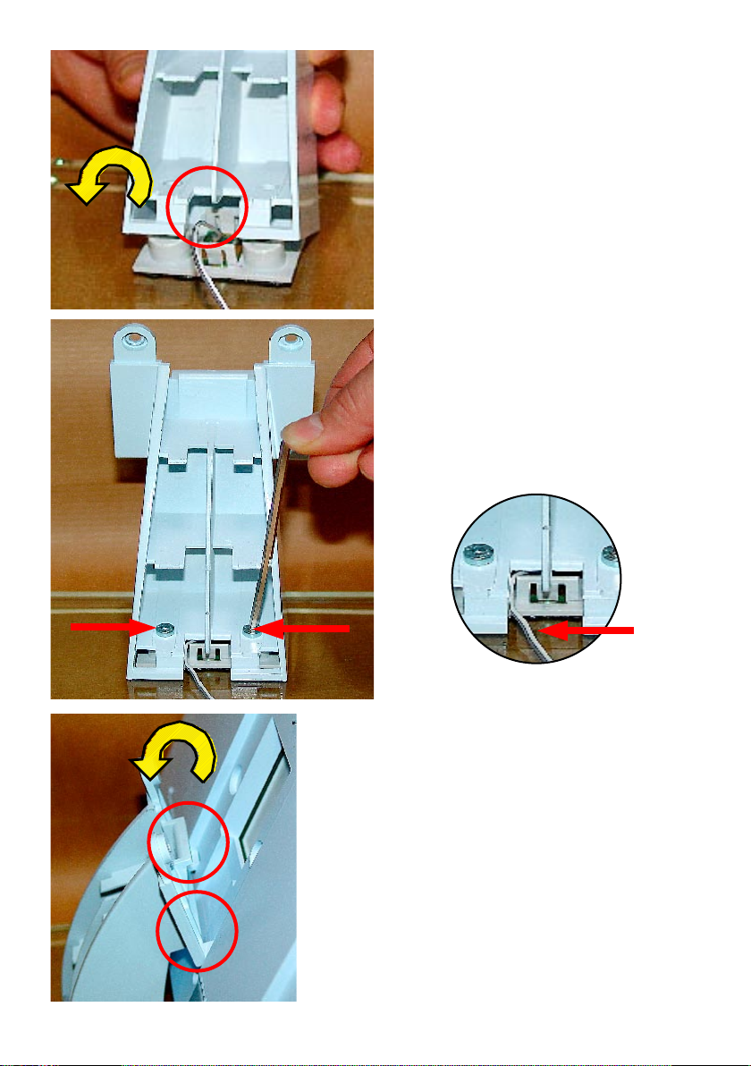
2. Lock in the foot support in the locking nose of the glass foot and place
it on the two screw domes.
3. Screw the enclosed Allen key and 2
Allen screws on the glass foot.
Please note that the lighting cable of
the device foot is guided in from the
side as shown in the picture so that
it does not get crushed.
4. Place t h e we a t her station at the
lock ing nose of the foot support
and tilt it on the foot support till the
screw dome neatly grips into the
corresponding intakes of the weather
station.
Note!
Do not let go of the weather station
till both the Allen screws have been
xed in (see next step)!
Ple ase do n ot p ress the disp lay
when you hold the weather station.
Hold the weather station only at the
frame!
10
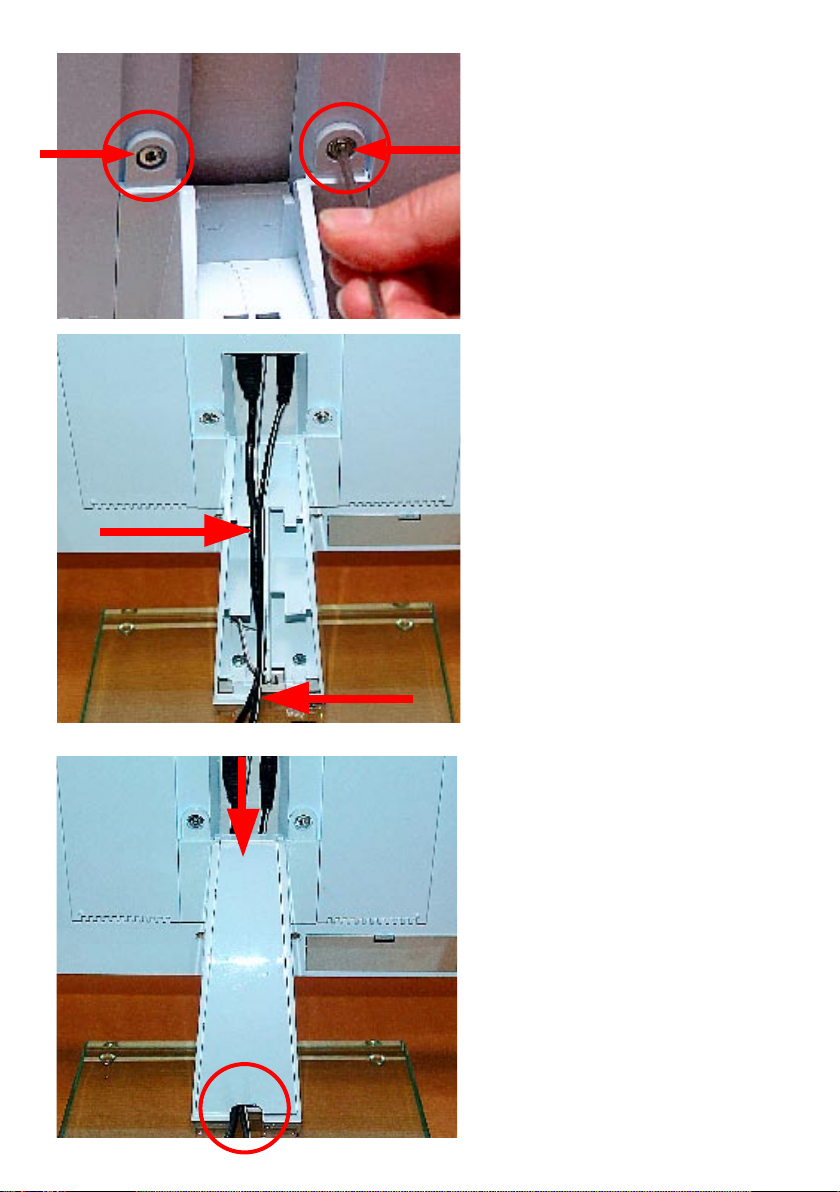
5. Screw the foot support on to
the weather station using the
enclosed Allen key and 2 Allen
screws.
6. The cables are thus connected,
inserted into the foot support
and guided. Please note that
the cable lies exactly in t he
center as shown so that it will
not prevent the lid from subsequently locking in.
Note!
The cable for lighting the sup-
port foot and the USB cable can
only be inserted in one direction!
Do not insert it using force!
Stow away excessive cable in
a chamber of the support.
11
7. Now place the cover for the foot
support:
Insert it at into the support in-
take (also see 1.), fold it upward
and lock it in.
Note!
The cover should fold up easily
without any resistance; otherwise, it means the cover has
not been placed properly or the
cable is not laid correctly in the
guide!
You can see the correct guiding
of the cable.

8. At the end, the cover is inserted
in the corresponding locks of the
cable shaft (see detailed picture
above), tilted upward and locked
in at the top (see lower picture).
12
Start-up (base station)
- After connecting the plug-in AC adapter, the system will run a short test of all
display segments in the display (all segments will be displayed).
- You will then hear a short beep and the version number of the weather station
will be displayed.
- Finally, the inside temperature and the humidity as well as the air pressure will be
displayed. The corresponding sensors are directly built in the base station.
- Now the external sensors need to be started up.
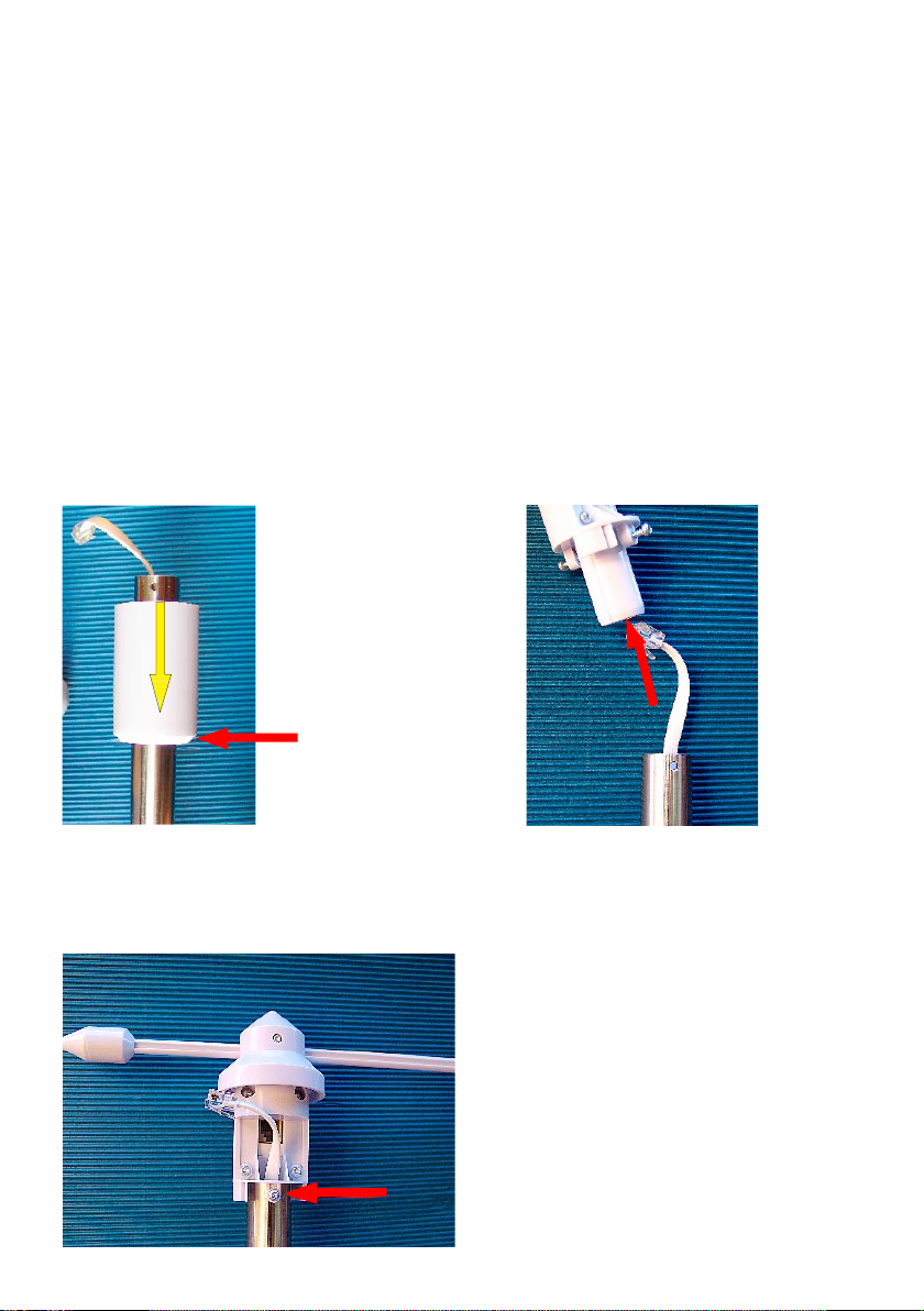
2.2. Combi-sensor TX 550
The combi-sensor is delivered as single parts and needs to be assembled before
start-up (for further information please refer to the TX 550 operating instructions).
- Remove the wind meter and base of the wind meter (small white cylinder), the
combi-sensor and the mounting pipes from the packaging.
- Mount the weather cock according to the following description:
Conical
side below
1. Mount the base of the wind meter on the
free end of the pipe of the combi-sensor
holder as shown in the diagram
2. Put cable through the foot
of the windcock
3. Insert the foot into the pipe and rotate
it in such a way that it can be locked in
the respective holes in the pipe using
the two screws
13
4. Insert the plug into the socket of the wind
meter
5. Push up the base and then lock it by
turning it to the right
- Put together the pipes of the insertion mast. The sensor-holder is mounted on the
pipe-end that is marked with a sticker.
- Install the fully mounted sensor within the possible transmitter radius (max. 400 ft.
free field; take into account the dampening due to building walls, etc.) so that
it stands in open space - the rain can thus fall directly into the rain sensor and
the wind measurement is not hampered by adjacent buildings or trees - 50 ft.
clearence.
A sunny location is possible because the temperature sensor is located in a shaded
and ventilated part of the housing.
- Bury the pressed end of the mast deep into the soil so that it stands securely
(approx. 15 inch depending on the condition of the soil). If the combi-sensor tilts
and falls, it can cause injury to persons and damage to vehicles and other objects.
Please note that the manufacturer is not responsible for injury or damage.
- Once the sensor is mounted, begin start up, and point the peak of the wind meter
towards the North to align the sensor. Lock, if required, the wind meter in this position
14
on the casing with the help of an adhesive tape.
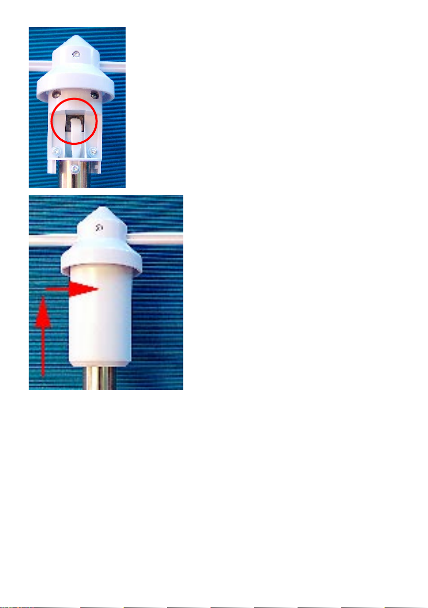
- Open the sensor housing by rotating it towards the left and pulling down the casing (see picture below).
- Use a pointed object to press the key above the battery compartment and insert
three AA Alkaline batteries according to the polarity marking in the battery compartment. Release the switch and then remove any adhesive tape that you may
used to secure the wind meter.
- Bring the respective receiving station in the receiving mode according to the
instructions of the corresponding Operating Instructions (also see chapter 3.1).
- Use a pointed object again to press the switch on the sensor. The receiving station should now register the data from the sensor.
- Close the casing again by pushing it upward and turning it to the right till it locks
in.
3. Operations
Remove
Turn to the left,
remove downward
Mount:
Mount,
turn to the right
Key
–
+
+
–
–
+
Bottom
Insert batteries, position of the key
The fully mounted TX 550 US
15

The wireless sensor data is not shown on the display immediately after installing
the wireless sensors and starting up the base device. As each sensor has an internal individual serial number, which is automaticly logged into the base station
during start up.
The advantage here is that data is individually recorded only for those sensors that
are logged in and not for other sensors, say of neighboring systems, and also not
after a restart.
Please note!
If no input eld is touched on entering data in the menu row for approx. 5 seconds,
then the device automatically goes back to the main menu (after including/saving any
settings that have been done). Hence wait for the main menu to be displayed after
you have entered data. You can thus quit each menu after making the settings.
Only touch the respective input elds slightly - do not press them! Do not press or
hit using any object!
The values can be set faster if you touch a setting eld for a longer time; the values
are then forwarded faster and you do not have to keep touching the setup elds.
3.1. Log in/delete external sensors
A total of 9 external sensors of the types TX 550 (1x), ASH 550, ASH 550-I and S 550 IA-
can be logged in. (Note: The ASH 550, ASH 550-I and S 550 IA are not currently available
for purchase.)
The memory slots 1..8 are reserved for ASH 550- (I) and S 550 IA.
The memory slot 9 has been reserved for the combi-sensor TX 550 .
assignment in case of multiple sensors of types ASH 550-(I),
or S 500 IA we recommend
that you rst remove the batteries from all the sensors.
For unique sensor
Logging in
- Touch the "CFG" eld in the menu row.
- You will see:
NEXT CLEANING ENTER
- Touch the "NEXT" eld, the display is:
NEXT SENSOR ENTER
- Touch the "ENTER" eld, the display is:
16

SENSOR NO 1 ADD DEL
- Repeatedly touch the "SENSOR" eld and select the memory slot where you want to
store the particular sensor. Please note that TX 550 can only be stored in slot 9.
- Then select "ADD"; the display is (for e.g. for sensor 9: TX 550):
SENSOR NO 9 - - SYNC ADD DEL
- The particular sensor is now taught to the system. Insert the batteries in the respective
sensor and press its key to teach. Please also read chapter 2.2 for starting up TX 550
and the operating instructions of the other sensor types.
The TX 550 data is then displayed automatically (after max. 6 minutes) in the correspond-
ing elds of the display - that of the remaining sensors after selecting the memory slot
("sensor" eld) in the "OUTDOOR" display eld.
Marking the populated memory slots
Memory slots that have already been populated are marked as "USED" behind
the memory slot number.
However, this does not indicate whether the respective sensor is actually active.
You can identify it only from the missing or outdated data when you select the
sensor and from the active reception indicator in the "OUTDOOR" eld.
Deleting a sensor assignment
The serial number of a sensor can be deleted from the sensor memory, if re-
quired.
- First proceed according to the instructions given under "Logging in"; select the
desired sensor and then select the "DEL" option instead of the "ADD" option.
- The "USED" lettering of the sensor number is deleted and the memory slot is thus
released again for logging in a sensor.
3.2. Operations
As all important data is displayed simultaneously in the display, operations are basically
Tip for initial senor set-up
To ensure proper set-up, please have the sensors and the receiving station 3 to 5 feet
apart. Note: The distance should not be less than 3 feet (1 m) apart.
17

restricted to selecting other sensors or some other weather data by slightly touching the
corresponding display eld.
The display is divided into display eld and menu row. In the normal mode (device
is in the main menu):
MIN MAX RESET CFG
are accessible by touching the respective fields of the display for the following
functions:
INDOOR: Switching between temperature and dewpoint display
("DEWPOINT")
OUTDOOR: Switching between temperature and dewpoint display
("DEWPOINT") and windchill display
HUMIDITY: No function
SENSOR: Switching between the external sensors:
1...8: Additional sensors not available
for purchase.
No display: TX 550-US
RAIN: Switching between total rain quantity since the last reset
("total"), current hour ("current 1h"), last hour ("1h"), current day ("current 24h") and last day ("24h").
(Storage
for hour: always at xx:30 hours; storage for day: always at
7:30 a. m.)
SUNSHINE DURATION: Switch between the sunshine duration of the current day
("h/day") and total sunshine duration since the last reset
("h")
TIME/DATE: No Function
WIND: Switch the numeric display between wind velocity in
km/h, m/s, mph and wind direction in degrees
AIR PRESSURE: Switch the air pressure display between the pressure
measured on site ("absolute") and the pressure scaled
down to sea level ("relative")
HISTORY: Switch the trend display of the last 24 hours between air
pressure, inside temperature and outside temperature (of
the displayed sensors), also see point 26 on page 7
Weather icon: No function
Main Menu Functions
18

MIN: Call up the minimum values
After touching the ”MIN” area, the minimum values of the respective data
are displayed. When you touch the corresponding eld (temperature, air
pressure, etc.), the corresponding time-stamp (date, time) of the occurrence of the extreme value are displayed.
You will go to the main menu and normal data display if your press "MIN"
again.
MAX: Call up the maximum values
After touching the "MAX" area, the maximum values of the respective data
are displayed. When you touch the corresponding eld (temperature, air
pressure, etc.), the corresponding time-stamp (date, time) of the occurrence of the extreme value are displayed.
You will go to the main menu and normal data display if your press "MAX"
again.
RESET: Reset certain values
This menu has three sub-menus for resetting the cumulated sunshine dura-
tion ("SUN"), rain quantity ("RAIN") or MIN-MAX-memory ("MIN-MAX"):
Activate "RESET". The rst RESET menu is displayed:
RESET RAIN OK
Repeatedly activate the "RESET" area and select the desired option and
then confirm by touching "OK". The corresponding data is now deleted
and the system automatically returns to the main menu and normal data
display.
However, if you do not want to delete data, then wait till the device returns
to the main menu. No data will be deleted.
CFG: Calling up the Conguration Menu
3.3. Conguration
19

The weather station is delivered in such a state that its basic functions (except moon
phase, sunrise, sunset, date, time, min./max. display) are ready to use without doing
any settings. However, another conguration would be needed to use the additional
functions and the time-related functions.
- Touch "CFG" eld to open the conguration menu.
- Repeatedly touch "NEXT" to go to the respective next main menu point of the
conguration menu. You will nd in the appendix a quick reference guide to access the dierent menus.
3.3.1. "SENSOR" menu, Login/ Delete sensors
see 3.1.
3.3.2. "TIME/DATE" menu, Set the time and date
- Select "TIME/DATE" menu:
NEXT TIME/DATE ENTER
- Touch the "ENTER" eld, the display is:
TIME 24H
- Touch the "24H" area to select between time display in 12 and 24 hour format.
- Touch the "TIME" eld, the display is:
YEAR + 2006 -
- Touch the "+" or "-" areas to set the year.
- Touch the "YEAR" eld, the display is:
MONTH + 07 -
- Touch the "+" or "-" areas to set the month.
- Touch the "MONTH" eld, the display is:
DAY + 01 -
- Touch the "+" or "-" elds till today's date (system date) is set.
- Touch the "DAY" eld, the display is:
WEEKDAY + MON -
20

- Touch the "+" or "-" areas to set the day of the week.
- Touch the "WEEKDAY" eld, the display is:
HOUR + 01 -
- Touch the "+" or "-" areas to set the hour.
- Touch the "HOUR" eld, the display is:
MINUTE + 01 -
- Touch the "+" or "-" areas to set the minute.
- Wait for a few seconds, then the time and date along with sunrise and sunset
times for the factory setting (39.8/-77.0 degress, Washington D.C.) and the current moon phase will appear on the display.
3.3.3. "UNITS" menu, Set the display units
- Select the "UNITS" menu:
NEXT UNITS ENTER
- Touch the "ENTER" eld, the display is:
TEMPERATURE DEG C
- Touch the "DEG" field to switch the display between degrees Celsius (C) or
Fahrenheit (F).
- Touch the "TEMPERATURE" eld, the display is:
PRESSURE HPA
- Touch the "HPA" field to switch the air pressure display between hPa (HPA),
mmHg (MMHG) and inHg (INHG).
- Touch the "PRESSURE" eld, the display is:
RAIN MM
- Touch the "MM" eld to switch between rain quantity display in mm (MM), inch
(INCH) or l/m2 (L/M2).
- Wait for a few seconds; the data will then be displayed in the units that have
been set earlier.
3.3.4. "POSITION" menu, Set position
21

The position details of the weather station location are needed to calculate the
sunrise and sunset times. You can enter the latitude in a range between –60.0° and
+60.0° and the longitude between - 180.0° and + 180.0°.
You can determine your position in dierent ways:
- The Appendix B contains a table with the coordinates for many US counties.
You can select a place in your vicinity and then enter its coordinates
- If you have a GPS navigation system in the car or a mobile device you can
take over the position details and you will thus have the exact location.
- You can also nd out the exact coordinates from the Internet.
- Select the "POSITION" menu:
NEXT POSITION ENTER
- Touch the "ENTER" eld, the display is:
LATITUDE + 38.9 -
- Touch the "+" or "-" areas to set the latitude.
- Touch the "LATITUDE" eld, the display is:
LONGITUDE + -77.0 -
- Touch the "+" or "-" areas to set the longitude.
- Wait a few seconds; you will then see the corrected day for sunrise and
sunset in the display.
Please note that the sunrise and sunset details will really be correct at the sea or for a
location on the plains. Mountains, high forests can really cut short the actual day.
The details can deviate slightly even for the ideal location because an
approximation formula is used for the calculations.
3.3.5. "TIMEZONE" menu, Set time zone
22

The time zone details are required for calculating the sunrise and sunset times. Enter
the current dierence to UTC (Coordinated Universal Time).
The Appendix C countains a table with the time zone difference from UTC for the
US.
- Select the "TIMEZONE" menu:
NEXT TIMEZONE ENTER
- Touch the "ENTER" eld, the display is:
TIMEZONE + - 05 -
- Touch the "+" or "-" areas to set the longitude.
- Wait a few seconds; you will then see the corrected day for sunrise and sunset
in the display.
3.3.6. "LIGHTING" menu, time setting for the background lighting and
regulating the brightness of the lightening
In this menu you can set the switching time for the background lighting that automatically switches on when you touch the screen and switches off after a set period. This can range from "OFF" (lighting never switches on), to periods between 5
seconds and 10 minutes till permanent lighting (ON). Further, you can also set the
times when the lighting should permanently be on.
You can also activate/deactivate an automatic adjustment to the surrounding brightness so that the display is optimally legible under all surrounding conditions.
The background lighting can only be used if you are connected to the AC adapter!
- Select the "LIGHTING" menu:
NEXT LIGHTING ENTER
- Touch the "ENTER" eld, the display is:
LIGHTING + 10 SEC -
- Touch the "+" or "-" areas to set the switch-on time.
- Touch the "LIGHTING" eld, the display is:
23

BRIGHT CTRL ON
- Touch the "ON" field to switch between "Automatic Brightness Control" being
active (ON) or deactive (OFF).
- Touch the "BRIGHT CTRL" eld, the display is:
BEGIN +04.00 PM-
- Touch the "+" or "-" elds to set the switching-on time of the lighting (permanent
lighting).
- Touch the "BEGIN" eld, the display is:
END +11.45 PM-
- Touch the "+" or "-" elds to set the switching-o time of the lighting (permanent
lighting).
- Wait for a few seconds, the device switches back to the normal mode and the
data that has just been set gets activated.
3.3.7. "SYSTEM" menu, System settings
In this menu you can do the settings for automatic daylight saving time switching
(DST, also see Appendix), for activating the beep (BEEP), for data recording interval
of the data logger (INTERVALL), for location altitude (ALTITUDE) and for comparing the rain sensor (RAIN CAL) and for comparing the brightness threshold for the
sunshine duration (SUN CAL).
Activate/deactivate Beep
- Select the "SYSTEM" menu:
NEXT SYSTEM ENTER
- Touch the "ENTER" eld, the display is:
BEEP ON
- Touch the "ON" field to switch between "Beep" being activated (ON) or deactivated (OFF).
Activate/ deactivate the daylight saving time switching
24

- Select the "SYSTEM" menu and then the "DST" option (via BEEP); the display is:
DST ON
- Touch the "ON" eld to switch between "daylight saving time switching" being
activated (ON) or deactivated (OFF).
Set the data recording interval for the data logger
The data recording interval for the data logger denes the intervals at which the
integrated data logger records are to be recorded. If you select a shorter interval,
then the recording time is also short and the record will be a detailed one. If
the intervals are longer, then the possible recording time is also longer and the
resolution of the weather data is lesser. This data can be useful if you are using
thrid party software. (Software not supported by manufacturer.)
- Select the "SYSTEM" menu and then the "INTERVALL" option (via BEEP, and
DST); the display is:
INTERVALL + 05 -
- Touch the "+" or "-" fields to set the interval time (OFF (data logger is off ), 5
minutes to 60 minutes). You will nd in the following section a few examples for
the relationship between interval time and recording time
Interval time Max. Recording time
5 minutes 10.4 days (250 hours)
10 minutes 20.8 days (500 hours)
30 minutes 62.5 days (1500 hours)
60 minutes 125 days (3000 hours)
"ALTITUDE", Adjust the location height above sea level
The standard altitude is used for calculating the relative air pressure at sea level
with reference to the absolute air pressure at the location. This relative value is
important as a reference for correctly interpreting the weather reports that refer to
the relative air pressure.
- Select the "SYSTEM" menu and then the "ALTITUDE" option (via BEEP, DST
and INTERVALL), the display is:
ALTITUDE ENTER
You can determine your height above sea level in dierent ways:
- You can find the height in a topographic map or ask your local land registry
oce.
- If you have a GPS navigation system in the car or a mobile device you can take
over the position details and you will thus have the exact location.
- You can also nd out the height above sea level from the Internet.
25

- Touch the "ENTER" eld, the display is:
ALTITUDE + 0000 -
- Touch the "+" or "-" elds to set the geographical altitude of this location above
sea level (height above sea level)
- Wait for a few seconds; the corrected data for the relative air pressure will then
appear on the display.
Alternatively, the value can also be entered via the optional PC program.
"RAIN CAL", Enter the comparison value for the rain sensor
The rain quantity measurement system has a high level of accuracy when it leaves
the factory; so normally, no adjustments are required.
The comparison value must firstly be determined in the normal mode according
to the steps described in "Calibrating the rainfall measurement recorder".
- Select the "SYSTEM" menu and then the "RAIN CAL" option (via BEEP, DST,
INTERVALL, ALTITUDE); the display is:
RAIN CAL ENTER
- Touch the "ENTER" eld, the display is:
RAIN CAL + 295 -
- Touch the "+" or "-" elds to set the value that has been calculated earlier.
- Wait for a few seconds; the device will then go back to the normal mode.
Alternatively, the value can also be entered via the PC program.
"SUN CAL“, Configure brightness threshold value for duration of sunshine
The weather station WS 2-550 nds out the sunshine duration along with the
combi-sensor TX 550 US. The threshold value is set at the base station and transferred to the combi-sensor. The latter performs the data evaluation:
Received brightness is higher than the threshold value → Sun is shining
Received brightness is lesser than the threshold value → Sun does not
shine
The brightness limit can be used to customize the sensor to the local conditions. The
26

threshold value should be dened at the start and end of sunshine so that the current
brightness value can be referred to the threshold.
- Select the "SYSTEM" menu and then the "SUN CAL" option (via BEEP, DST,
INTERVALL, ALTITUDE, RAIN CAL), the display is:
SUN CAL ENTER
- Touch the "ENTER" eld, the display is:
SUN CAL 131 + 085 -
Reduce the threshold value
Currently set threshold value
Increase the threshold value
- Touch the "+“ or "-“areas to set the threshold value. The setting area ranges
Current brightness value
1
from 0 to 255.
- Wait a few seconds; the device switches back to the normal mode.
1
You cannot directly convert to the brightness intensity unit Lux.
3.3.8. "CLEANING", menu, Cleaning mode
As the display gets dirty due to touching, it needs to be cleaned now and then using
a dry soft cloth (the best option is to use a spectacles cleaning cloth; however, do
not use any cleaning liquids as they can damage the display). To prevent the station
from getting displaced while cleaning, there is a cleaning mode where all the touch
elds are locked for approx. 20 seconds.
- Select the "CLEANING" menu:
NEXT CLEANING ENTER
- Touch the "ENTER" eld, the display is:
CLEANING START
- Touch the "START" eld, the display is:
CLEANING WAIT
- The display can now be cleaned. Normal display resumes after 20 seconds.
3.3.9. "LIVE MODE" menu, call up the current weather data ow
27
In this mode, another key of the combi-sensor can be prompted to send its measurement data for 20 seconds at 2 seconds interval. Thus, at the press of a key one
has the latest weather data and can thus follow the wind direction and the trend of
wind velocity for say 20 seconds.
As the combi-sensor frequently goes into the receive mode when the "LIVE MODE"
is activated, its power consumption increases and this has an eect on the life of the
battery. Hence you can use the "LIVE MODE" to set a period for which the "LIVE
MODE" should be activated.
In this period, the main menu bar will show the additional "REQ" key that was used
to query the above-mentioned live data.
- Select the "LIVE MODE" menu:
NEXT LIVE MODE ENTER
- Touch the "ENTER" eld, the display is:
BEGIN +04.00 PM-
- Touch the "+" or "-" elds to set the switching-on time of the "LIVE MODE".
- Touch the "BEGIN" eld, the display is:
END +11.45 PM-
- Touch the "+" or "-" elds to set the switching-o time of the "LIVE MODE".
- Wait for a few seconds, the device switches back to the normal mode and the
data that has just been set gets activated.
- In the menu bar, data transfer to the combi-sensor is indicated with the message: "WAIT FOR TRANSMISSION". The weather station cannot be operated
till this display is on.
- The REQ key for calling data appears in the menu when the "LIVE MODE" is
activated:
MIN MAX RESET REQ CFG
3.4. Other Functions and Displays
28

Display moon phases
The moon phases are displayed using the following symbols:
Moon phase may vary from your calendar by 1-2 days. Also keep in mind that the
moon display will be blank during a new moon and dark during a full moon.
Oscar Outlook
Oscar Outlook is an animated gure that simultaneously displays multiple weather
factors:
Outside temperature (only combi-sensor)
- The clothing status is based on how high the temperature is on the combisensor.
Rain
- If the weather forecast has announced rain, then the figure holds a closed
umbrella.
- The gure carries an opened umbrella when it starts raining.
Wind velocity
- If the wind velocity is higher than 12.4 mph (20 km/h, medium wind) Oscar
Outlook`s hair starts uttering. At the same time, if the temperature is below
57.2 °F (14 ˚C), then even the scarf he is wearing starts uttering.
Weather forecast
- The weather forecast symbols indicate the following forecasts:
· Clouds with rain
· Clouds
· Clouds with sun → Bright
· Sun → Sunny
Waxing
→ Cloudy
New moon
→ Rainy
WaningFull moon
Wind symbol display (wind sock)
- The wind sock symbol in the forecast display eld shows at a glance whether the
wind is currently mild, medium or strong:
· Wind sock is hanging down → mild wind (<6.2 mph)
· Wind sock is raised half
· Wind sock is horizontal
Immediate Rain Display
→ strong wind (>12.4 mph)
→ medium wind (6.2 to 12.4 mph)
29

- The onset of rain is notified to the base station during the next wireless data
transmission and is indicated through a cloud in the "RAIN" eld and through the
opened umbrella of "Oscar Outlook".
Comfort Indicator
- The Comfort Indicator (LKJ) reflects the climate in the room (ratio of temperature to humidity). The Appendix contains a value table for the display areas.
History
- The bar diagram shows the history of air pressure, outside or inside temperature
for the last 24 hours. The individual columns are not an absolute value but only
the dierence to the currently measured value (0h column). This reference point is
always located in the center (4 bars) so that the trend is visible at a single glance
(see also page 18).
Data memory
- If the data memory is almost full, the menu bar displays the message:
MEMORY ALMOST FULL OK
- Touch and confirm this input field and download the collected data using the
PC.
Data transfer to the combi-sensor "WAIT FOR TRANSMISSION"
- When the "WAIT FOR TRANSMISSION" message is displayed in the menu bar,
the weather station transfers data to the combi-sensor, i.e. it activates the live
mode or the conguration data of the sunshine duration.
This transaction can take a few minutes; the weather station cannot be operated
during this period.
Temperature trend display
- On the right, next to the temperature display, a trend arrow is displayed next to the
display fields "Indoor" and "Outdoor" if the temperature in the last transmission
interval has increased (upward arrow) or decreased (downward arrow).
Sensor Status Display
30

- In the outdoor sensor display eld ("Outdoor") there is a small reception indicator
to indicate the sensor status:
· Reception indicator is displayed → Sensor data is being received
constantly
· Reception indicator is blinking → Sensor data is not being
received since the last 40 min.
· Reception indicator is missing → Sensor does not exist,
permanently out of order or defect
Warning against turbulent weather
- When a low pressure area is suddenly formed, there is a warning symbol in the
display field of the weather forecast. This is an indicator of an upcoming storm
or thunderstorm.
Frost warning
- A snow-ake symbol is displayed in the weather forecast eld if the temperature
measured at the combi-sensor falls below 39.2 °F (4 ˚C).
4. Changing the batteries
Base station
When the battery empty symbol appears in the INDOOR display area ( ), then
all batteries are to be replaced according to the instructions in section 2.1 with
those of the same type.
Always change all the 4 batteries and use only high-quality alkaline batteries. Leave
the AC adapter connected when you are changing the batteries so as to avoid
data loss.
Please note!
The data memory is deleted if you do not connect the AC adapter while replacing the
batteries.
31

Wireless sensors
The batteries in these sensors have a lifetime of max. 2 years (alkaline batteries).
They are to be replaced when a 'battery empty' symbol ( ) is displayed when
you select the corresponding sensor in the "OUTDOOR" display area.
Batteries are replaced in TX 550 according to the instructions in section 2.2.; the instructions for the other sensors are to be found in the respective operating instruction manuals.
Please follow the battery disposal regulations!
Do not dispose of disposable and rechargeable batteries as part of
household garbage!
5. Troubleshooting
Po ssible dis ruptio ns t h at ca n ha mper proper dis play of t he tr ansmit ted
measured values are:
No reception - the distance between the transmitter and receiver is too much
or too less (<3 ft., 1 m).
Reduce or increase the distance between the transmitter / receiver.
No reception - there are highly resistant materials (thick walls, steel concrete, ...)
located between the transmitter and the receiver
Relocate the transmitter or receiver. Also see chapter 6 ("Range").
No reception - transmitter batteries are empty.
Replace batteries.
No reception - transmitter is covered by the disturbance source
(Wireless device, wireless headphone/ loudspeaker)
Remove the source of the fault and look for another position for the transmitter and
receiver. Such disturbances are only for a short period (wireless traffic) or can be
rectied in a very simple manner. Any wireless headphones, wireless baby phones
or similar devices are operated at a frequency of 916.5 MHz in your house or in the
vicinity only for a short duration. Most of these devices are enabled for exchanging signals at an interruption-free frequency. Such a measure can eectively fade
out all interruptions.
No reception – Log in of sensor was not successful.
Execute log in procedure again. Refer page 13 of the manual and follow the instructions of the
receiver station.
32

Inaccurate rain
Be sure rain gauge is assembled correctly, with drain holes aligned.
Check that sensor assembly is not tipped, but straight into ground.
Check rain gauge for debris that may be blocking the funnel, rocker (pointer) or drain hole.
Check that the rocker (pointer) is set properly.
Is the rain measurement unit correct? Ex: mm, inch or l/m².
Check the calibration of the rain sensor according 6.2.
Inaccurate wind
Check that sensor assembly is not tipped, but straight into ground.
Are surrounding areas clear of trees, buildings and other obstructions?
Check that the cups spin freely.
Is the wind measurement unit correct? Ex: mph, m/s or km/h.
No sunshine duration
Check that sensor assembly is not tipped, but straight into ground.
Check for debris in vented cap.
If possible: Adjust sunshine calibration. Follow the instructions of the receiver station.
No Min/Max display
Has time and date been set?
Sunrise/set time wrong
Has time and date been set?
Has latitude and longitude been set?
Has time zone been set?
Wireless sensor is disrupting the functioning of other devices in the 868 MHz band.
The transmission of the wireless outdoor sensor can be briey interrupt (every 2-3
minutes for approx. 100 ms) the functioning of other devices on the same channel.
Other instructions for start-up or troubleshooting
Turn the receiving weather station slightly; if there is no reception, mount it away
from electrical motors, electrical machines, televisions, computer monitors and
large metal surfaces. Also see chapter 13 (FCC Information)
To simplify start-up, you can also bring the sensors rst close to the base station (min. 3
ft. distance). You can then properly control the data transmission from the sensor.
6. Range
33

The free-eld range for visual contact between transmitter and receiver is 400 ft. (120 m)
under optimal conditions. Walls and even steel concrete structures may be penetrated;
however, the range is then reduced accordingly. Reduced range can be caused by the
following:
· High frequency disturbances of all types
· All types of structures or vegetation
· The distance between the sensor and the receiver to the conducting areas or
objects (and even to the human body or the earth) has an eect on the transmission properties and in turn the range.
· Broadband disruptions in city areas can reach levels that reduce the signal-noise
distance in the entire frequency range and in turn reduce the range.
· Devices with adjoining working frequencies can also have an effect on the receiver.
· PCs with poor shielding can interfere with the receiver and reduce the range.
7. Instructions for Maintenance and Care
- Protect the base station against dust and moisture. Never clean it with chemical
detergents; just use a soft dry piece of linen. Do not put any pressure on the
display.
- The outdoor sensor is to be cleaned from time to time to remove the dirt and dust
that has settled on it. Check easy accessibility of the wind sensors and ensure
that the sensors are tting tight on the holder.
7.1. Cleaning the rain quantity sensor
- Depending on the location, leaves, dirt, sand and branches blown by the wind
34

get collected in the collection funnel of the rain quantity sensor. Larger parts can
block the passage. Sand can also accumulate on the pointer; large deposits of
it can hamper the measurement result.
- Hence the rain quantity sensor is to be cleaned from time to time - at least once
a year. The pictures shown below are a guideline for installing / dismantling.
- For cleaning the sensor, just remove the sensor housing by slightly turning it to
the left.
- Further, the collection funnel can also be removed by turning it to the left.
- The rainfall sensor is now moved upward, folded towards the cable side and you
can now remove the pointer.
- Clean the collection funnel, contacts, counter and the drain-hole in the housing
and remove all residues.
- Place the counter back in its holder. The magnet of the counter should be on the
side that faces the cable.
- Insert the rain sensor in its holder. It will also automatically hold the pointer. The
rain sensor cable and the magnet of the pointer must be located on the same
Pointer inserted correctly
Lock for collection funnel
Housing locked in correctly at the bottom (collection funnel removed for demonstration)
Drain hole
Rainfall sensor inserted correctly
Remove
Turn to the left,
remove casing
downward,
remove collection
funnel upward
Mount
Mount,
turn to the right
35

side.
- Now place the collection funnel from the top on to the sensor-holder and lock it
in by turning it to the right.
- Now reinstall the casing and lock it by turning it to the right in the sensor-holder till
it locks in. Ensure that the drain-holes of the casing and the sensor-holder match
(drain-hole of the casing points outwards).
7.2. Setting the rain sensor
The rain quantity measurement system has a high level of accuracy when it
leaves the factory; so normally, no adjustments are required.
Adjustments would be necessary only if the accuracy requirements are very
high.
Before you start calibrating the rain water measurement recorder, you need to reset
to zero the rainfall quantity value that has already been totaled up (see chapter 3.2.
"RESET"), total rain quantity display stands at zero). Further, the rainfall quantity
for adjustments must be displayed in "inch".
Proceed as follows for exact calibration:
1. Slowly pour 3.38 fl. oz. (100 ml) water over a period of 10 minutes in the rain
sensor collection funnel.
Note!
Quick pouring will give wrong measurement results! Pour the water so
slowly into the funnel that there is a even passage of water and there is no
water in the funnel at any point of time.
2. The displayed total quantity should now be 0.26 inch (6.5 l/m2).
3. If a dierent value is shown, then the calibration value that is mentioned is to
be recalculated as follows:
0.26 x Current calibration value
New calibration value =
Actual value (Display reading after lling in the water)
The new calibration value must now be entered in the configuration menu (see
3.3.7., System menu/RAIN CAL).
The factory setting is 295/pointer stroke.
36

8. Technical Specications
Measurement interval for outdoor sensors ...................................................................... 2-3 min
Measurement interval for indoor sensor (Temperature, humidity) ............................. 3 min
Interval for measuring air pressure ........................................................................................15 min
Transmission frequency ......................................................................................................... 868 MHz
Outdoor range: .....................................................................................................................max. 120 m
Indoor temperature range: ............................................................ 32 °F to 140 °F (0 °C to 60 °C)
Resolution: ........................................................................................................................................ 0.1 °C
Accuracy: .........................................................................................................±1.8 °C (59 °F to104 °F)
Outdoor temperature range (TX 550): ...........................-20 °F to 175.8 °F (-29 °C to 79.9 °C)
Resolution: ........................................................................................................................................ 0.1 °C
Accuracy: .........................................................................................................±1.4 °F (50 °F to 104 °F)
Measurement range rel. humidity (inside/outside) ........................................1% rH - 99 % rH
Resolution: .......................................................................................................................................1 % rH
Accuracy: ............................................................................................................± 5 % rH (30-70 % rH)
Rain quantity display: .......................................................................0 to 39.3 inch (0 to 999 mm)
Evaluation interval: .........................................................................................last hour: at xx:30 hrs
.........................................................................................................................................day: at 7:30 a. m.
Resolution: ....................................................................................................up to 10 inch: 0.01 inch
.............................................................................................................................above 10 inch: 0.1 inch
Wind velocity: ....................................................................................0 to 124 mph (0 to 200 mph)
Resolution: ....................................................................................................up to 100 mph: 0.1mph
............................................................................................................................ above 100 mph: 1 mph
Wind direction: ........................................................................................................................ 0° to 355°
Resolution: ................................................................................................................................................5°
variation range: ............................................................................................±0°;±22.5°; ±45°; ±67.5°
Voltage supply:
Base station (Main power supply): ..................................7.5 V DC via plug-in mains adapter
Base station (back-up power supply): .......................................................... 4 x Battery AA cells
TX 550 : .....................................................................................................................3 x Battery AA cells
Dimensions Base station without foot (W x H x D): ................................10.2 x 8.5 x 1.3 inch
...................................................................................................................................(260 x 215 x 32 mm)
Instructions for disposal
Do not dispose of the device as part of household garbage!
37

9. PC connection - Third Party Software Installation
You may visit www.weather-display.com to download third party software. Please
note that the manufacturer does not support the software.
The enclosed USB cable with type A connector and mini type B connector is required
for connecting to the USB port.
- Con nect t he weat her st ation v ia the USB c able t o the USB p ort of the
computer.
38

10. Appendix
Dewpoint - Temperature point that is independent of the interaction between a
specic air pressure level, a specic temperature and a certain level of humidity. The
humidity in the air starts to condense at this point, the so-called dew; the humidity
condenses and precipitates as liquid (mist, vapor). If the dewpoint for water vapor
is below 32 °F (0 ˚C), then there is condensation in the form of snow or hoar frost.
Weather forecast - Forecast about weather symbols calculated from the increasing
or decreasing speed of air pressure (trend).
These changes in the air pressure speed is the most decisive dimension for the
forthcoming weather; the absolute value has a lesser role to play. One can generally say that the increasing air pressure would mean better weather and falling air
pressure would then be a sign of bad weather.
Windchill-Equivalent-Temperature - A fictional temperature that is felt by human
beings under certain conditions instead of the measured temperature and which
can be taken into account during low temperatures (for e.g. under 44 °F) to find
out how one would feel at certain temperatures, wind velocities and corresponding clothing. These conditions are a temperature below 91.4 °F (33 ˚C) and a wind
velocity above 5.8 mph (2.6 m/s). Windchill is defined as the cooling effect of the
naked skin at assumed constant 91.4 °F (33 ˚C) skin surface temperature.
The higher the wind velocity and the lower the actual temperature, the stronger is
then the windchill eect.
The "felt" temperature is an approximation that can be compared to the so-called
feeling about the temperature and is taken into account along with the effect of
the emission eects of the sun, light reection of the clouds, the light wave length,
etc.
Wind strength table (Beaufort)
Beaufort Wind velocity km/h Wind velocity mph Description
0 0 - 0.7 km/h 0 - 0.4 mph calm
1 0.7 - 5.4 km/h 0.5 - 3.6 mph light air
2 5.5 - 11.9 km/h 3.7 - 7.4 mph light breeze
3 12.0 - 19.4 km/h 7.5 - 12.1 mph gentle breeze
4 19.5 - 28.5 km/h 12.2 - 17.7 mph moderate breeze
5 28.6 - 38.7 km/h 17.8 - 24.0 mph resh breeze
6 38.8 - 49.8 km/h 24.1 - 30.9 mph strong breeze
7 49.9 - 61.7 km/h 31.0 - 38.3 mph near gale
8 61.8 - 74.6 km/h 38.4 - 46.4 mph gale
9 74.7 - 88.9 km/h 46.5 - 55.2 mph strong gale
10 89.0 - 102.4 km/h 55.3 - 63.6 mph storm
11 102.5 - 117.4 km/h 63.7 - 72.9 mph violent storm
12 > 117.4 km/h > 72.9 mph hurricane
39

Comfort indicator
The symbol of the comfort indicator (the three different "smiles" J K L) reflect
the room climate whereby the weather station works according to the following
table:
Temperature air humidity
20% 30% 35% 40% 45% 50% 55% 60% 65% 70%
<64.4 °F
L L L L L L L L L L
64.4 - 67.8 °F
67.9 - 71.4 °F
71.5 - 75.0 °F
75.1 - 78.6 °F
78.7 - 82.2 °F
over 82.2 °F
L L L K K K K K K L
L L L K J J J J K L
L L K J J J J K L L
L K J J J J K L L L
L K K K K K K L L L
L L L L L L L L L L
One can thus see that depending on the relationship of the temperature to humidity, there are certain marked ranges that can be dened as comfortable or uncomfortable climate. One would thus feel that at a temperature of 77 °F (25 ˚C) and a
humidity of less than 30% is very dry (for e.g. air from the heaters) and one above
60% as sultry.
Daylight saving time switching
The integrated clock implements an automatic daylight saving time switching according to the regulations of the “Energy Policy Act of 2005”.
11. Proper use, Exclusion of warranty, Safety instructions
- This weather station is meant for personal use as an indicator of the forthcoming
weather. The forecasts or predictions made by this device are more for orientation
and are not to be construed as absolute forecasts.
- The manufacturer of the weather station does not assume any liability for incor-
rectly measured values and consequences that can result from it.
- This weather station is not meant for medical purposes or for informing the pub-
lic.
- The components of this weather station are not a toy; they contain many fragile,
glass and small parts. Please install all the components out of the reach of children.
40

12. Wireless technology BidCoS™
BidCoS (Bidirectional Communication Standard) is a new wireless standard
that has been specially developed for wireless control of sensors and actors
for house automation. It allows you to build an entire house controlling system
with compatible components: switch/dim lights and other electrical appliances,
air-conditioners (heating, cooling, airing, weather measuring technology, energy
management, access control, protection against burglary, safety devices, etc.).
Speedy bi-directional communication (wireless signals that are sent are conrmed
by the receiver) increases the functional safety and thus form the basis for a multitude of options for remote control / remote monitoring.
Bi-directional data transfer of WS 550 US to TX 550 and all additional sensors
works according to BidCoS Standard.
41

13. FCC Information
Contains FCC ID: RNT-TRX916
Changes or modifications not expressly approved in writing by La Crosse Technology may void the user’s authority to operate the equipment.
NOTE: This equipment has been tested and found to comply with the limits for a
Class B digital device, pursuant to Part 15 of the FCC Rules. These limits are designed to provide reasonable protection against harmful interference in a residential
installation. This equipment generates, uses and can radiate radio frequency energy
and, if not installed and used in accordance with the instructions, may cause harmful
interference to radio communications. However, there is no guarantee that interference will not occur in a particular installation. If this equipment does cause harmful
interference to radio or television reception, which can be determined by turning
the equipment o and on, the user is encouraged to try to correct the interference
by one or more of the following measures:
- Reorient or relocate the receiving antenna.
- Increase the separation between the equipment and receiver.
- Connect the equipment into an outlet on a circuit different from that to
which the receiver is connected.
- Consult the dealer or an experienced radio/TV technician for help.
The internal antenna used for this mobile transmitter must provide a separation
distance of at least 7.874 in (20 cm) from all persons and must not be co-located
or operating in conjunction with any other antenna or transmitter.
DoC Statement
This device, trade name La Crosse Technology, model number WS 2-550 complies with
Part 15 of the FCC Rules. Operation is subject to the following two conditions:
(1) this device may not cause harmful interference, and
(2) this device must accept any interference received, including interference
that may cause undesired operation
The responsible party for this device compliance is:
La Crosse Technology
6A Rue du commerce
67118 GEISPOLSHEIM - FRANCE
42
Appendix A: Menu Overview WS 550 US
Main menu
MIN
MAX
RESET RESET RAIN
RESET SUN
RESET MIN-MAX
CFG CLEANING
SENSOR
LIGHTING LIGHTING
BRIGHT CTRL
BEGIN
END
TIME/DATE TIME
YEAR
MONTH
DAY
WEEKDAY
HOUR
MINUTE
LIVE MODE BEGIN
END
UNITS TEMPERATURE
PRESSURE
RAIN
POSITION LATITUDE
LONGITUDE
TIMEZONE
SYSTEM BEEP
DST
INTERVALL
ALTITUDE
RAIN CAL
SUN CAL
43

Appendix B: Table of latitude/longitude of French counties.
State County Latitude Longitude
FRANCE
Dép Villes Latitude Longitude
01 BOURG 46°12 5°13
02 LAON 49°34 3°37
03 MOULINS 46°34 3°20
04 DIGNE 44°05 6°14
05 GAP 44°33 6°05
06 NICE 43°42 7°16
07 PRIVAS 44°44 4°36
08 MEZIERES 49°46 4°44
09 FOIX 42°57 1°35
10 TROYES 48°18 4°05
11 CARCASSONNE 43°13 2°21
12 RODEZ 44°21 2°34
13 MARSEILLE 43°18 5°22
14 CAEN 49°11 359°38
15 AURILLAC 44°56 2°26
16 ANGOULEME 45°40 0°10
17 LA ROCHELLE 46°10 358°50
18 BOURGES 47°05 2°23
19 TULLE 45°16 1°46
20 AJACCIO 41°55 8°43
21 DIJON 47°20 5°02
22 ST-BRIEUX 48°31 357°15
23 GUERET 46°10 1°52
24 PERIGUEUX 45°12 0°44
25 BESANCON 47°14 6°12
26 VALENCE 44°56 4°54
27 EVREUX 49°03 1°11
28 CHARTRES 48°27 1°30
29 QUIMPER 48°00 355°54
30 NIMES 43°50 4°21
31 TOULOUSE 43°37 1°27
32 AUCH 43°30 0°36
33 BORDEAUX 44°50 359°26
34 MONTPELLIER 43°36 3°53
35 RENNES 48°06 358°20
36 CHATEAUROUX 46°49 1°41
37 TOURS 47°23 0°42
38 GRENOBLE 45°11 5°43
39 LONS-LE-SAUNIER 46°41 5°33
40 MONT-DE-MARSAN 43°54 359°30
41 BLOIS 47°36 1°20
42 ST-ETIENNE 45°26 4°23
43 LE PUY 45°03 3°53
44 NANTES 47°14 358°25
45 ORLEANS 47°54 1°54
46 CAHORS 44°28 0°26
47 AGEN 44°12 0°38
48 MENDE 44°32 3°30
49 ANGERS 47°29 359°28
50 ST-LO 49°07 358°55
51 CHALONS-S-MARNE 48°58 4°22
52 CHAUMONT 48°07 5°08
53 LAVAL 48°04 359°15
54 NANCY 48°42 6°12
55 BAR-LE-DUC 48°46 5°10
56 VANNES 47°40 357°16
57 METZ 49°07 6°11
58 NEVERS 47°00 3°09
59 LILLE 50°39 3°05
60 BEAUVAIS 49°26 2°05
61 ALENCON 48°25 0°05
62 ARRAS 50°17 2°46
63 CLERMONT-FERRAND 45°47 3°05
64 PAU 43°18 359°38
65 TARBES 43°14 0°05
66 PERPIGNAN 42°42 2°54
67 STRASBOURG 48°35 7°45
68 COLMAR 48°05 7°21
69 LYON 45°46 4°50
70 VESOUL 47°38 6°09
71 MACON 46°18 4°50
72 LE MANS 48°00 0°12
73 CHAMBERY 45°34 5°55
74 ANNECY 45°54 6°07
75 PARIS 48°52 2°20
76 ROUEN 49°26 1°05
77 MELUN 48°32 2°40
78 VERSAILLES 48°48 2°08
79 NIORT 46°19 359°33
80 AMIENS 49°54 2°18
81 ALBI 43°56 2°08
82 MONTAUBAN 44°01 1°20
83 TOULON 43°07 5°55
84 AVIGNON 43°56 4°48
85 LA-ROCHE-SUR-YON 46°38 358°30
86 POITIERS 46°35 0°20
87 LIMOGES 45°50 1°15
88 EPINAL 48°10 6°28
89 AUXERRE 47°48 3°35
90 BELFORT 47°38 6°52
91 EVRY 48°38 2°34
92 NANTERRE 48°53 2°13
93 BOBIGNY 48°55 2°27
94 CRETEIL 48°47 2°28
95 PONTOISE 49°03 2°05
44

La Crosse Technology, Ltd provides a 1-year limited warranty on this product against manufacturing
defects in materials and workmanship.
This limited warranty begins on the original date of purchase, is valid only on products purchased
and used in North America and only to the original purchaser of this product. To receive warranty
service, the purchaser must contact La Crosse Technology, Ltd for problem determination and service
procedures. Warranty service can only be performed by a La Crosse Technology, Ltd authorized
service center. The original dated bill of sale must be presented upon request as proof of purchase
to La Crosse Technology, Ltd or La Crosse Technology, Ltd’s authorized service center.
La Crosse Technology, Ltd will repair or replace this product, at our option and at no charge as
stipulated herein, with new or reconditioned parts or products if found to be defective during the
limited warranty period specified above. All replaced parts and products become the property of
La Crosse Technology, Ltd and must be returned to La Crosse Technology, Ltd.
Replacement parts and products assume the remaining original warranty, or ninety (90) days, whichever is longer. La Crosse Technology, Ltd will pay all expenses for labor and materials for all repairs
covered by this warranty. If necessary repairs are not covered by this warranty, or if a product is
examined which is not in need or repair, you will be charged for the repairs or examination.
The owner must pay any shipping charges incurred in getting your La Crosse Technology, Ltd
product to a La Crosse Technology, Ltd authorized service center.
Your La Crosse Technology, Ltd warranty covers all defects in material and workmanship with
the following specified exceptions: (1) damage caused by accident, unreasonable use or neglect
(including the lack of reasonable and necessary maintenance); (2) damage occurring during shipment (claims must be presented to the carrier); (3) damage to, or deterioration of, any accessory or
decorative surface; (4) damage resulting from failure to follow instructions contained in your owner’s
manual; (5) damage resulting from the performance of repairs or alterations by someone other than
an authorized La Crosse Technology, Ltd authorized service center; (6) units used for other than
home use (7) applications and uses that this product was not intended or (8) the products inability
to receive a signal due to any source of interference.
This warranty covers only actual defects within the produc t itself, and does not cover the cost
of installation or removal from a fixed installation, normal set-up or adjustments, claims based
on misrepresentation by the seller or performance variations resulting from installation-related
circumstances.
LA C ROSSE TE CHNOLO GY, LT D WI LL N OT AS SUM E L IABILIT Y F OR I NC IDENTAL, CONSEQU ENTIAL, PU NIT IVE, OR OTHER SIMILAR DAMA GES AS SOC IATED WITH THE OPERATION
OR MALF UNC TIO N OF TH IS PRODU CT. THIS P RODUCT IS NOT TO BE USED FOR MEDI CAL
PU RPO SES O R FOR P UBLI C INF ORMAT ION . THIS PROD UCT IS NOT A TOY. K EEP OUT OF
CHILDREN’S REACH.
This warranty gives you specic legal rights. You may also have other rights specic to your State.
Some States do no allow the exclusion of consequential or incidental damages therefore the above
exclusion of limitation may not apply to you.
For warranty work, technical support, or information contact:
All rights reserved. This handbook must not be reproduced in any form, even in excerpts, or duplicated or processed using electronic, mechanical or chemical procedures without written permission
of the publisher.
This handbook may contain mistakes and printing errors. The information in this handbook is regularly checked and corrections made in the next issue. We accept no liability for technical mistakes
or printing errors, or their consequences.
All trademarks and patents are acknowledged.
WARRANTY INFORMATION
La Crosse Technology
6 A Rue du commerce
67118 GEISPOLSHEIM - FRANCE
e-mail:
contact@lacrossetechnology.fr
(warranty work)
contact@lacrossetechnology.fr
(information on other products)
web:
www.lacrossetechnology.fr
45

La Crosse Technology
46
 Loading...