


Before commencing assembly, please read these instructions thoroughly!
R
THE FINEST RADIO CONTROL MODELS
For Advanced Flyers
|
|
INSTRUCTION MANUAL |
|
RADIO CONTROLLED ENGINE POWERED SCALE AIRCRAFT
WINGSPAN: 1172mm |
S-2C 40 |
INDEX |
|
● |
2 |
REQUIRED FOR OPERATION |
|
● |
2 |
BEFORE YOU BEGIN |
|
● |
3~15 |
ASSEMBLY |
|
● |
15 |
SPARE PARTS |
|
● |
15~16 |
OPERATING YOUR MODEL SAFELY |
|
|
SAFETY PRECAUTIONS |
! |
This radio control model is not a toy! |
● |
●First-time builders should seek the advice of experienced modellers |
|
before commencing assembly and if they do not fully understand |
|
any part of the construction. |
● |
●Assemble this kit only in places out of children’s reach! |
|
●Take enough safety precautions prior to operating this model. |
||
● |
|||
You are responsible for this model’s assembly and safe operation! |
|||
|
|||
●Always keep this instruction manual ready at hand for quick |
|||
● |
|||
reference, even after completing the assembly. |
|
||
|
|
||
|
|
||
SPECIFICATIONS ARE SUBJECT TO CHANGE WITHOUT NOTICE. |
No. 11061 |
||
© 2001 KYOSHO |
|
|
|
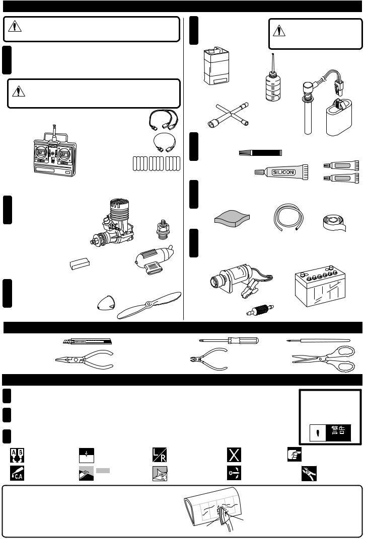
REQUIRED FOR OPERATION (Purchase separately!)
|
|
|
CAUTION: For details concerning the equipment listed below |
|
(size, maker, etc.), check with your hobby shop. |
1 5x 5 x 3x 2
A 4 Channel radio with 5 standard servos is required.
( ) (4 )( )
CAUTION: Only use a minimum 4 channel transmitter, configured |
|
for aircraft! |
|
■4 |
■ …1 |
A minimum 4 channel transmitter, |
1 x Y-Lead |
configured for aircraft. |
|
■ …1  1 x Extension Lead


■3…12 


 AA AA AA
12 AA-size Batteries
Ensure you read and understand the instructions included with your radio.
2
Engine and Muffler
■
Model Aircraft Engine
2 40 ~ 46 4 48 ~ 53
2 Stroke .40 ~ 46 4 Stroke .48 ~ .53
■2
Muffler extention 


 adapter (2 Stroke)
■Muffler
■Glow Plug
3 |
■ |
■ |
|
Propeller and Spinner |
Spinner 62mm |
Propeller |
|
Purchase a propeller thatwill match your engine.
|
|
|
|||
4 Required for engine starting: |
|
|
|||
■ |
|
|
WARNING: Normal gasoline |
||
|
|
cannot be used with |
|||
Glow engine fuel only. |
glow engines. |
||||
|
|||||
|
|
■ |
■ |
||
M OD E L |
|
|
|||
Fuel Bottle |
One-touch Plug Heater Set |
||||
EN |
GIN E |
||||
FUE L |
|
|
|
||
■Plug Wrench
5 Glue |
|
■ (30 ) |
|
|
■ |
|
|
|
|
Epoxy Glue (30 minutes type) |
|
|
Instant Glue |
|
|
|
|
|
|
|
■ |
|
Epoxy A |
|
|
|
|
|
Silicon Glue |
|
Epoxy B |
6 Others |
■ |
||
|
■ |
Silicone Tube ■ |
|
|
Vibration Protection Sponge |
|
Double-side Tape |
7 |
|
|
|
Other equipment for enhancing airplane operation & performance |
|||
|
■ |
■12V |
|
|
Engine Starter |
|
12V Battery (for starter) |
■
Fuel Filter
TOOLS REQUIRED (Purchase separately!)
■ |
■ |
■ |
Sharp Hobby Knife |
Phillips Screwdriver (L, M, S) |
Awl |
■ |
■ |
■ |
Needle Nose Pliers |
Wire Cutters |
Scissors |
BEFORE YOU BEGIN
1
Read through the manual before you begin, so you will have an overall idea of what to do.
2
Check all parts. If you find any defective or missing parts, contact your local dealer or our Kyosho Distributor.
3
Symbols used throughout this instruction manual, comprise:
●
Do not overlook thissymbol!
 Warning!

 2mm
2mm
Apply epoxy glue. 2mm Drill holes with the specified diameter (here: 2mm).
|
|
|
|
|
Apply instant glue |
|
|
|
|
|
|
Cut off shaded portion. |
||
(CA glue, super glue). |
|
|
||
|
|
|
|
|
Assemble left and right sides the same way.
Cut away only film.
|
|
|
Must be purchased |
||
Pay close attention here! |
||
separately! |
||
|
||
|
|
|
Ensure smooth non-binding |
||
Cut off excess. |
||
movement while assembling. |
||
|
The pre-covered film on ARF kits may wrinkledue to |
|
|
variations of temperature. Smooth out as explained right. |
|
low setting |
|
with cover (cloth) |
|

 Use an iron covered with a cloth! Start at low setting. Increase the set-- ting if necessary. If it is too high, you may damage the film.
2

1
Upper Main Wing
0 |
Dihedral (0 ) |
 Warning!

Apply epoxy glue to wing spar halves and join together. When dry, apply epoxy to one end of wing spar and insert into wing. Wipe away excess and
let dry. Apply fresh glue to other half of spar and mating surfaces of wing and join. Secure with tape until dry.
2
Lower Main Wing

Note the direction. Top
84mm |
|
Dihedral 84mm at wing tip. |
Fill the gap with epoxy. |
|
84mm
 Warning!

Join lower wing halves together as for the upper wing(shown above), being careful to check dihedral.
3
Main Wing


Before cutting away the covering film, lightly heat that area with an iron.

Align the centre of the main wing with the aileron.

Wing Underside

Carefully apply instant glue to both sides of the hinge, ensuring free movement.

Pay close attention here!


Apply epoxy glue.
Cut away only film.
Ensure smooth non-binding movement while assembling.
Apply instant glue (CA glue, super glue).
Assemble left and right sides the same way.
●
Do not disregard this symbol!
 Warning!
3
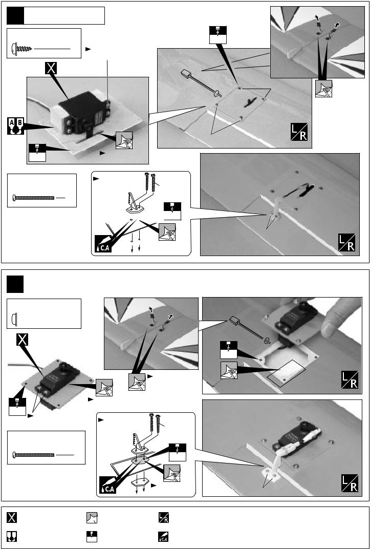
4 |
|
● |
Lower Main Wing |
When using mini servos. |
|
2.6 x 8mm TP |
2mm |
|
|
Screw |
|
|
8 |
|
|
|
Included with the radio set. |
|
|
|
|
Aileron Servo |
|
 2.6x8mm

Cut away only film.
2.6x8mm
2.5mm |
|
|
|
Cut away only film. |
|
||
2 x 20mm |
Apply C/A into holes |
2 x 20mm |
|
to harden surfaces. |
|||
Screw |
|||
|
|
||
|
4 |
|
 2mm
2mm
2x20mm


Cut away only film.
5 |
|
● |
Lower Main Wing |
When using standard servos. |
2.6 x 8mm TP Screw


 8
8
Aileron Servo
|
Cut away only film. |
|
|
|
|
2.5mm |
|
Cut away only film. |
|
|
Apply C/A into holes |
|
|
|
Included with the radio set. |
2 x 20mm |
|
|
to harden surfaces. |
||
|
|
||
2 x 20mm |
|
|
|
|
Screw |
|
|
|
4 |
|
2mm |
|
|
|
|
|
Cut away only film. |
 2.6x8mm
2mm

Cut away only film.
2x20mm
Must be purchased separately!


Apply epoxy glue.
 Cut away only film.
 2mm
2mm
2mm Drill holes with the specified diameter (here: 2mm).
Assemble left and right sides the same way.
Apply instant glue (CA glue, super glue).
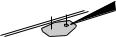
4
6 |
|
● |
Lower Main Wing |
When using standard servos. |

Double-side Tape
7 |
( ) |
|
|
|
|
|
|
|
|
|
|||
|
|
|
|
|||
Lower Main Wing |
|
4mm |
Align with the holes in the main wing. |
|||
|
|
|
|
|||

Cut away only film.
8 |
|
A = A’ |
|
Lower Main Wing / Fuselage |
|
||
4 x 30mm |
|
|
|
|
Screw |
|
|
|
2 |
|
|
4 x 12mm |
A |
A’ |
|
|
Washer |
||
|
2 |
|
|
|
|
4 x 30mm |
|
|
|
4 x 12mm |
|
 2mm
2mm
2mm Drill holes with the specified diameter (here: 2mm).


Apply epoxy glue.
Cut off shaded portion.
Assemble left and right sides the same way.
|
|
Temporarily tighten. |
Must be purchased separately! |
|
|
Pay close attention here! |
Fix it with the both sides tape. |
Cut away only film.
5
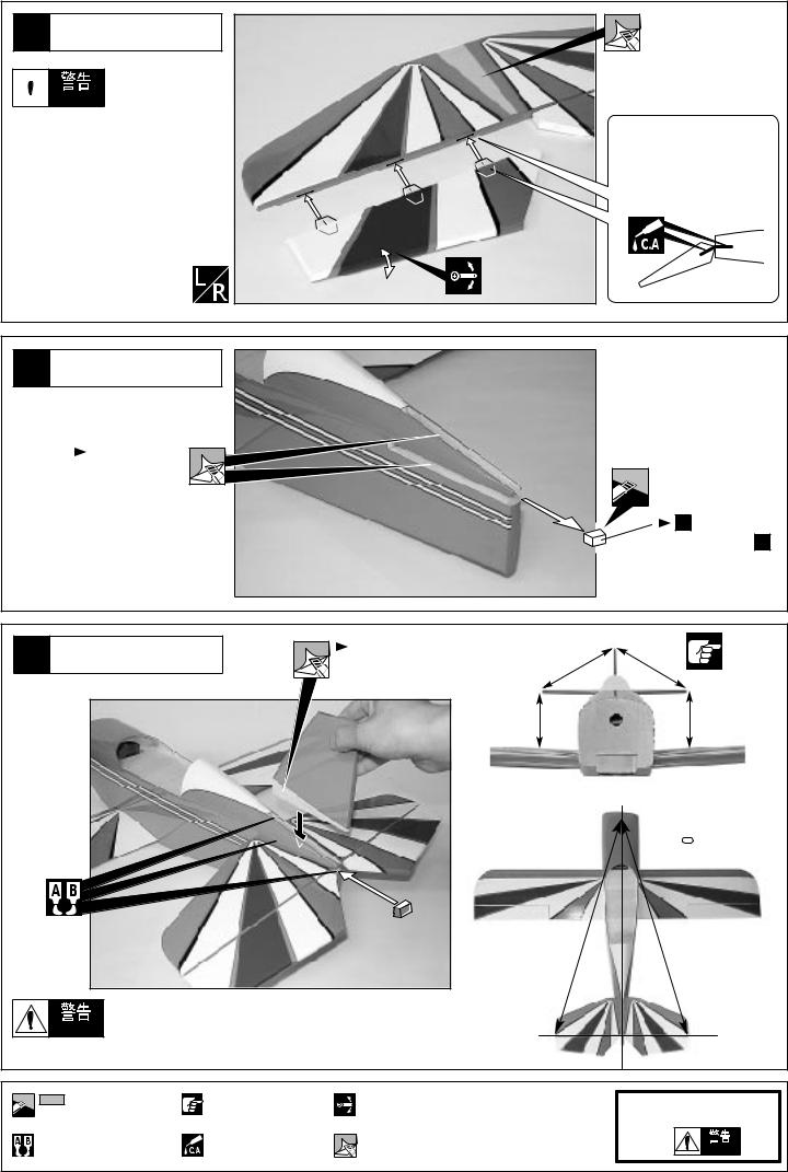
9
Horizontal Tail (Stabilizer)
 Warning!

Securely glue together. If the wing separates during flight, you will lose control of your airplane.


Cut away only film.

Carefully apply instant glue to both sides of the hinge, ensuring free movement.
10 |
|
|
|
|
|
Vertical Tail (Rudder) |
|
|
|
|
|
|
|
|
|
|
|
|
Cut away only film. |
|
|
|
|
|
|
|
|
|
11 |
|
|
|
|
Use this part in Step 11 . |
|
|
|
|
|
|
A = A’ |
11 Vertical / Horizontal Tail |
Cut away only film. |
B |
B’ |
B = B’ |
|
|
|
||||
|
|
|
A |
|
A’ |
 C = C’
C |
C’ |

Warning! Securely glue together. If the wing separates during flight, you will lose control of your airplane.
|
|
|
|
Cut off shaded portion. |
Pay close attention here! |
Ensure smooth non-binding |
|
movement while assembling. |
|||
|
|
●
Do not overlook this symbol!
|
|
|
Warning! |
Apply epoxy glue. |
Apply instant glue |
Cut away only film. |
|
(CA glue, super glue). |
|
|
|
|
|
|
6
 Loading...