


Before use, please carefully read the explanations!
INSTRUCTION MANUAL
R
THE FINEST RADIO CONTROL MODELS
RADIO CONTROLLED
.30 ENGINE POWERED
HELICOPTER
SERIES
30 S S


 NEXUS 30 S TYPE S
INDEX
●REQUIRED FOR OPERATION |
|
2 |
●RADIO PREPARATION |
|
3 |
●BEFORE YOU BEGIN |
|
4 ~ 5 |
●ASSEMBLY |
6 |
~ 24 |
●OPERATING YOUR MODEL SAFELY |
|
25 |
●SETTINGS FLIGHT LESSONS MAINTENANCE |
26 |
~ 35 |
●PARTS LIST |
|
36 |
●EXPLODED VIEW |
37 |
~ 41 |
●SPARE & OPTIONAL PARTS |
42 |
~ 44 |
● ( )
●
●
●
●
SAFETY PRECAUTIONS
This radio control model is not a toy.
●This is a kind of machine including a rotor which rotates with high speed and has a possibility to be dangerous. You are responsible for this model's assembly, safe operation (place to fly, frequency) check and adjustment of the model.
●Assemble this kit only in places out of children's reach! ●Take enough safety precaution before and after operation.
After every flight, inspect screws and nuts for looseness, and parts for wear. Any damaged parts should be immediately replaced, repaired or adjusted for safe operation.
●Use only Kyosho genuine parts for replacement.
Failing to do so will result in accidents or malfunction of the model. Kyosho do not take responsibilities for the accidents and crashes if using the parts which are not Kyosho genuine ones.
●Always keep this instruction manual ready at hand for quick reference, even after completing the assembly.
SPECIFICATIONS ARE SUBJECT TO CHANGE WITHOUT NOTICE.
© 1997 KYOSHO
No. 21702
No. 21705
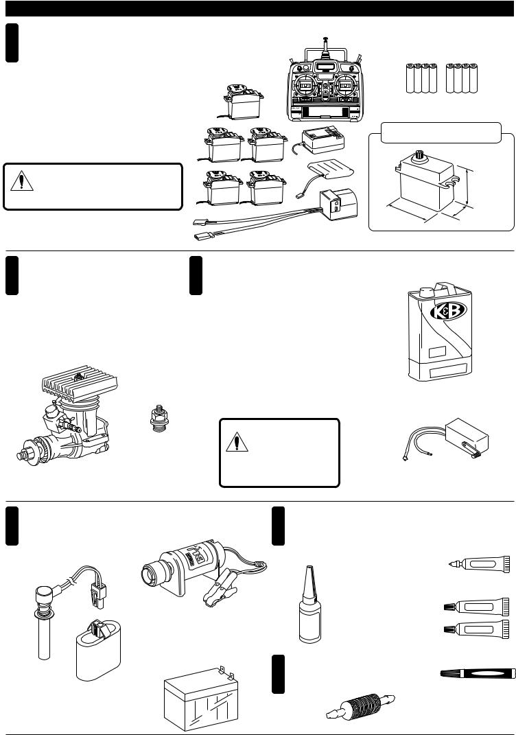
REQUIRED FOR OPERATION (1)
1
Radio for engine-powered R/C helicopters, and dry batteries
● 5+
●
●This kit requires a radio for engine-powered R/C helicopters with 5 servos and 1 gyro.
●For more information on the radio, refer to its explanations.
|
|
|
|
|
CAUTION: Only use a radio for R/C heli- |
copters! (Any other radio is prohibited!) |
■ |
■ |
Radio for engine-powered |
AA-size Batteries (for transmitter) |
R/C helicopters |
|
AA AA
SUITABLE SERVOS
|
33 ~ 36mm |
39 ~ 41mm |
19 ~ 20mm |
|
Futaba
The illustrations showing the radio were taken from the Futaba radio explanations.
2 Engine
●
●With semi-assembled kits, the engine coms pre-installed. Install the muffler.
3
Glow Fuel and Fuel Pump ■
● Glow Fuel
● 10
■ 30
.30 class engine for helicopters
■
Glow Plug
●Engines for R/C models require glow fuel. Do not use gasoline or kerosene; both cannot be used! Also, be very carefulwhen handlingglow fuel which is highly- inflamma-- ble and high-explosive!
●Fuel should contain at least 10% of nitro.
500H |
|
|
|
mod |
el en |
gine |
fuel |
|
|||
|
|
||
●No. 6054 K&B500H
K&B500H Model Engine Fuel
■
Fuel Pump
使用禁止
WARNING: Gasoline or kerosene cannot
be used!
4
Required for engine starting:
■
■ Starter
Plug Heater
●No. 1791
Blitz Starter
■ 12V
12V Battery
●No. 71481
Sealed Battery
●No. 96411
One-touch Plug Heater
(12V-6.5A)
5
6
Glues & Lubes |
■ |
|
■ |
Grease |
|
No. 96506 |
||
Screw Locking Compound / |
||
Ball Diff Grease |
||
Screw Cement / Threadlocker |
||
|
||
|
Grease |
|
● Loctite |
■ |
|
No. 94402 |
Epoxy Glue |
|
Medium Strength |
Epoxy A |
|
|
||
No. 94403 |
|
|
Hard Strength |
Epoxy B |
|
|
||
|
■ |
|
|
Instant Glue |
|
Equipment coming in handy |
|
|
■ |
●No. 96627 |
|
|
||
Fuel Filter |
||
GelBoy |
||
|
||
●No. 1876/No. 39308 |
||
Fuel Filter |
|
|
2
1
2
3
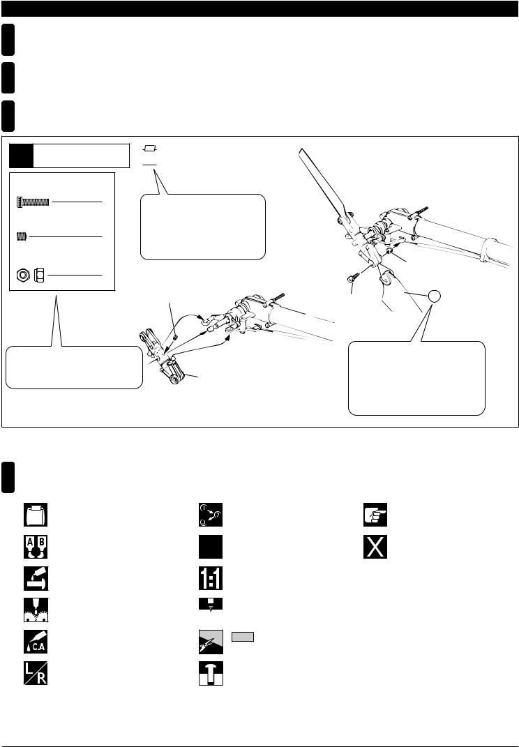
BEFORE YOU BEGIN (1)
Read through the manual before you begin, so you will have an overall idea of what to do.
Check all parts. If you find any defective or missing parts, contact your local dealer or our Kyosho Distributor.
How to read the instruction manual: |
Example |
|
9 |
|
Tail |
|
2.6 x 10mm |
|
|
Cap Screw |
|
2 |
3 x 3mm |
|
|
Set Screw |
|
1 |
2.6mm |
|
|
Nylon Nut |
|
2 |
 HH-2
HH-2
This instruction manual uses several symbols. Please note them during the entire assembly.
|
|
2.6mm |
3 x 3mm |
2.6 x 10mm |
92 |
|
|
Key Number, Part Name, True-to-scale |
|
Diagram, Quantity Used |
Tail Rotor Assembly
No.
No.
All parts except screws are identified by key numbers. For purchasing spare parts, find the key no. of the part needed in the spare part list and refer to the left column to look up the corresponding order no.
4
Symbols used throughout the instruction manual, comprise:
Part bags used.
|
x2 |
|||
|
|
|
||
Apply epoxy glue. |
|
|
|
|
|
|
|
|
|
Apply threadlocker (screw cement). |
|
|
|
|
|
|
|
|
|
|
|
|
||
2mm |
||||
Apply grease. |
||||
|
|
|
||
|
|
|
|
|
Apply instant glue (CA glue, super glue).
Assemble left and right sides the same way.
Assemble in the specified order.
Assemble as many times as specified (here: twice).
True-to-scale diagram.
2mm
Drill holes with the specified diameter (here: 2mm).
Cut off shaded portion.
Tentatively tighten.
Pay close attention here!
Must be purchased separately!
4
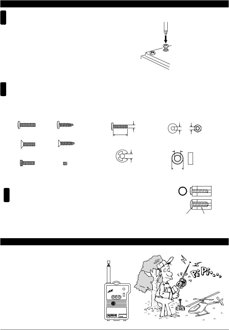
BEFORE YOU BEGIN (2)
5
Inside the kit, you will find assemblies, i.e. sections that are pre-assembled and hence consist of more than one part. To make sure these assemblies are safely assembled, check among others their screws for looseness. Only then, build in the assemblies.
6
This kit contains screws and hardware in different metric sizes and shapes. Before using them, check the screws on the true-to-scale diagrams on the left side in each assembly step. Some screws are extras.
● SCREWS |
|
● OTHER HARDWARE |
|
Screw |
TP |
3x12mm |
3mm |
|
Self-tapping (TP) Screw |
Screw |
Washer Nut |
|
|
3mm |
3mm |
|
|
|
|
|
TP |
12mm |
|
Flat Head (F/H) Screw |
TP F/H Screw |
|
|
|
|
E4 |
5x10mm |
|
|
E-ring |
5mmMetal Bushing Bearing |
|
|
||
Cap Screw |
Set Screw |
4mm |
|
|
|
|
10mm |
7 TP
Self-tapping (TP) screws cut threads into the parts when being tightened. Excessive force may permanently damage parts when tightening TP screws. It is recommended to stop tightening when the part is attached or when some resistance is felt after the threaded portion enters the plastic.
Correct
Wrong 
|
|
Overtightened. |
The threads are stripped. |
ABOUT THE "PERSONAL FREQUENCY MONITOR"
するとブザー音とLED
Before operating your helicopter, plug the crystal of your frequency into the Personal FrequencyMonitor. As soon as you switch it on, you'll know for sure through an interfe-- rence signal and LED lamps whether somebody else is on your frequencyor not!
No.80591 (40MHz)
No.80592 (72MHz)
●6,000
Special crystals are available at Kyosho!
PERSONAL 40MHZ BAND MONITOR 
KYOSHO CORPORATION ON
OFF
No.80591
JRMSA 77
KYOSHO CORPRATION
5
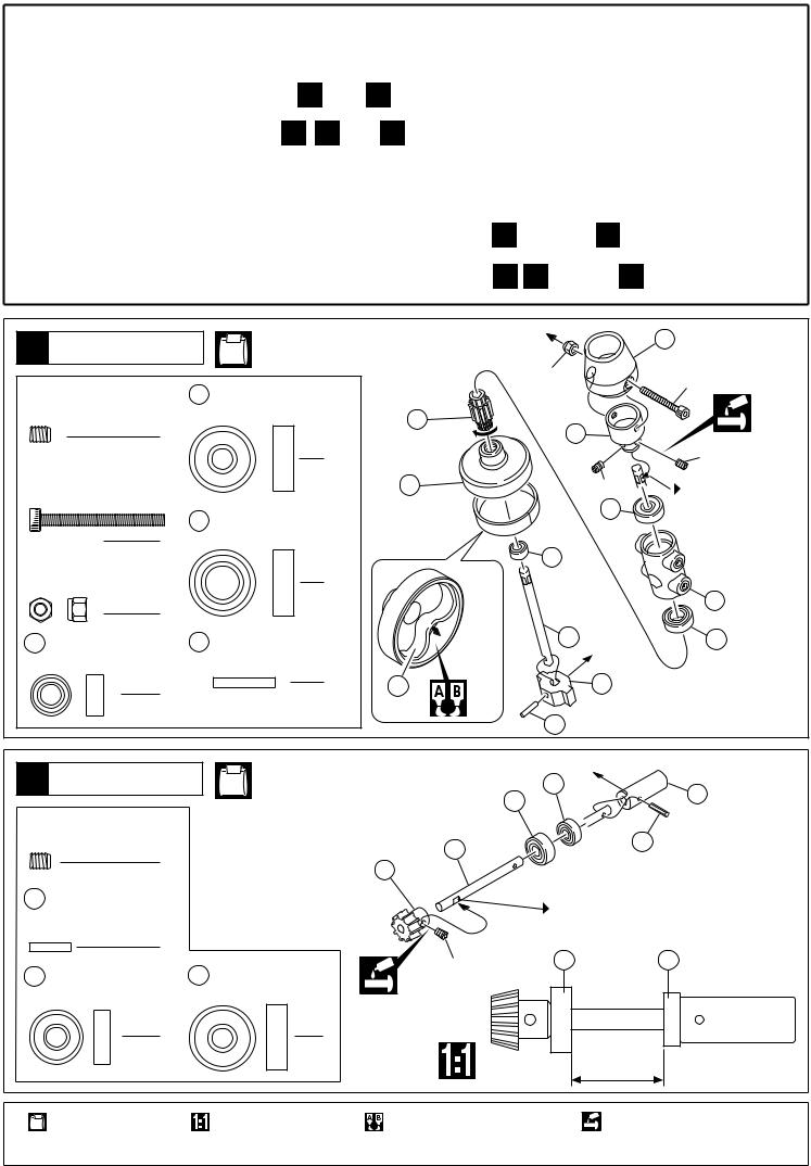
● No.21705 No.21702
1 49
15 28 49
● This instruction manual is both for kit No.21705 and semi-assembled kit No.21702 with engine.When referring to the instructions for completing the assembly, make the following distinctions.
NEXUS 30S type S (assembly kit) |
: All steps from |
1 |
through 49 . |
||||
NEXUS 30S type S (semi-assembled) : All steps from |
15 |
28 through |
49 . |
||||
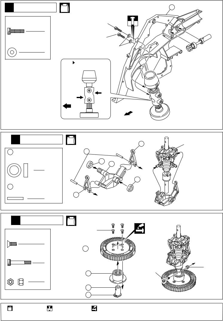
1 Clutch |
NE-B, NE-6 |
|
|
3mm |
385 |
||
|
|
|
|
|
|
3×30mm |
|
|
|
|
|
|
|
|
|
4×5mm |
18 5×16mm |
|
|
|
|
||
Set Screw |
Ball Bearing |
382 |
|
|
|
||
|
|
|
|
|
|
|
|
|
|
2 |
|
|
|
384A |
|
|
|
|
1 |
|
|
|
4×5mm |
3×30mm |
|
381 |
|
4×5mm |
|
||
Cap Screw |
|
|
|||||
|
|
|
|
|
|||
|
|
|
|
|
|
18 |
|
|
|
|
49 8×16mm |
|
|
Firmly tighten the set |
|
|
|
|
|
|
|
||
|
|
1 |
Ball Bearing |
|
|
|
screw to the flat. |
|
|
|
|
|
|
|
|
3mm |
|
|
|
83 |
|
||
|
|
|
|
|
|||
|
Nylon Nut |
1 |
|
|
|
||
|
|
pre-installed |
|
||||
|
|
|
|
|
|
383 |
|
|
|
1 |
|
|
|
|
|
|
|
|
|
|
|
|
|
83 |
5×10mm |
379A 2.5×15mm |
|
380A |
49 |
||
|
|
Ball Bearing |
Pin |
|
pre-installed |
||
|
glued |
|
|||||
|
|
|
1 |
|
|
||
|
|
1 |
209 |
|
378 |
|
|
|
|
|
|
|
|
|
|
|
|
|
|
|
|
|
|
|
|
|
|
|
|
379A pre-installed |
|
|
|
NE-2, NE-6 |
|
|
|
|
|
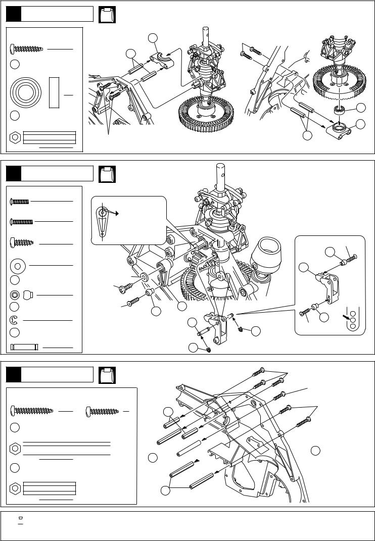
2 Tail Drive Gear |
|
|
56 |
57 |
|||
|
|
18 |
|
||||
|
|
|
|
|
|
||
|
|
|
|
|
|
|
|
4×5mm |
|
|
|
|
|
||
Set Screw |
|
419 |
|
|
58 |
||
|
|
|
|
|
|
|
|
|
|
1 |
|
386 |
|
|
|
|
|
|
|
|
|
|
|
58 |
2×10mm |
|
|
Spring Pin |
|
|
Firmly tighten the set screw to the flat. |
|
|
|
1 |
|
|
|
|
|
|
4×5mm |
18 |
56 |
56 5×13mm |
18 5×16mm |
|
|
|
|
|
|
||
Ball Bearing |
Ball Bearing |
|
|
|
1 |
1 |
|
|
|
|
|
|
|
22.5mm |
|
|
|
|
|
Part bags used. |
True-to-scale diagram. |
Apply epoxy glue. |
|
Apply threadlocker |
|
|
|
|
(screw cement). |
6
|
|
|
369 |
3 Frame |
NE-5 |
|
|
|
|
||
3×12mm |
3×12mm |
|
|
Cap Screw |
|
|
|
|
|
|
|
2 |
|
|
|
3×8mm |
3×12mm |
|
|
|
|
|
|
Washer |
|
3×8mm |
|
|
|
|
|
2 |
|
|
|
|
|
|
|
|
Note the direction. |
|
|
|
|
|
|
|
Front |
|
|
|
|
Front |
|
4 Mast |
NE-2, NE-3, NE-4 |
31 |
|
|
|
||
|
|
|
Mast Assembly |
371 8×12mm |
59 |
|
|
Plastic Bushing |
|
|
|
|
371 |
374 |
|
|
|
|
|
2 |
|
|
|
|
|
371 |
|
59 2×14mm |
|
|
|
Pin |
|
|
|
|
31 |
|
|
2 |
|
|
|
|
|
|
|
5 Main Gear |
NE-4 |
|
|
3×8mm |
3×8mm |
|
|
|
|
|
|
F/H Screw |
|
|
|
4
503 


 3×18mm


Cap Screw
|
1 |
|
|
3mm |
|
3mm |
|
|
3×18mm |
||
Nylon Nut |
48 |
||
|
1
46
150
|
|
|
Part bags used. |
Tentatively tighten. |
Apply threadlocker |
|
|
(screw cement). |
7
6 Mast |
|
NE-2, NE-5, NE-6 |
|
||||
3×15mm TP |
|
|
388 |
|
|
||
|
Screw |
|
|
|
3×15mm |
||
|
|
4 |
|
373 |
|
|
|
|
|
|
|
|
|
|
|
49 |
8×16mm |
|
|
|
|
|
|
|
Ball Bearing |
|
|
|
|
|
|
|
|
1 |
|
|
|
|
|
|
|
|
|
|
|
|
49 |
373 |
S |
|
|
|
|
|
|
|
Insert Nut (S) |
|
|
|
|
387 |
|
|
|
|
3×15mm |
|
|
373 |
|
|
|
|
|
|
|
||
|
|
4 |
|
|
|
|
|
|
|
|
NE-4 |
|
|
|
|
7 Control Lever |
|
|
|
|
|||
|
|
|
|
|
|||
2×8mm |
|
|
|
|
|
||
RT/H Screw |
|
|
|
|
|
||
|
|
2 |
|
|
|
|
|
2×10mm |
|
|
|
|
|||
RT/H Screw |
|
|
|
||||
|
Align both marks. |
|
|
||||
|
|
1 |
|
|
|
||
3×10mm TP |
|
|
|
|
|
||
|
Screw |
|
|
|
|
2×8mm |
|
|
|
1 |
|
|
|
|
|
3×8mm |
|
|
|
|
212 |
||
|
|
|
|
|
|||
|
Washer |
|
|
|
|
|
|
|
|
1 |
|
|
|
|
188 |
|
|
|
|
|
|
|
|
212 |
|
|
3×8mm |
|
|
|
|
3×10mm |
|
|
|
||||
|
Linkage Ball |
|
|
|
|||
|
|
3 |
|
|
|
|
|
230 |
E E2.0 |
2×10mm |
212 |
418 |
|
||
|
E-ring |
|
|
|
|
212 |
|
|
|
2 |
|
|
|
33 |
|
|
|
|
|
|
|
||
|
|
|
|
|
|
2×8mm |
|
|
|
|
|
|
|
|
|
33 |
3×14mm |
|
|
|
|
230 |
|
|
Shaft |
|
|
|
|
|
|
|
|
1 |
|
|
|
230 |
|
|
|
|
NE-5 |
|
|
3×15mm |
|
8 Frame |
|
|
|
|
|
||
|
|
|
|
|
|
||
|
|
|
|
|
|
|
3×15mm |
3×20mm TP |
3×15mm TP |
|
|
|
|||
|
Screw |
|
Screw |
|
|
3×20mm |
|
|
|
|
|
|
|
|
|
|
|
2 |
|
4 |
|
373 |
|
372 |
L |
|
|
|
|
|
|
|
Insert Nut (L) |
|
|
|
|
|
|


 370 4 372


373 S
Insert Nut (S)
372
2

Part bags used.
8
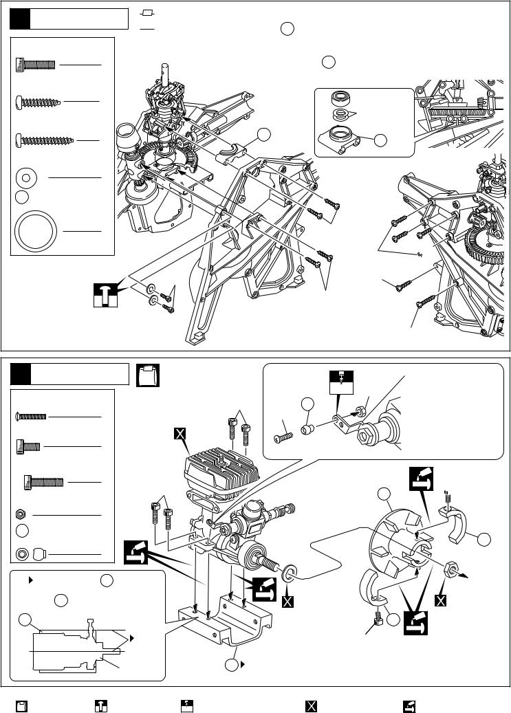
9 Frame |
|
3×12mm |
|
Cap Screw |
|
|
2 |
3×15mm TP |
|
|
Screw |
|
8 |
3×20mm TP |
|
|
Screw |
|
2 |
3×8mm |
|
|
Washer |
|
2 |
535 13×16mm |
|
|
Shim |
|
2 |
 NE-5, NE-6
3×12mm
●
387
Main Gear Backlash Adjustment.
Remove the 387 lower ball bearing case and insert shims as per diagram. The number of shims used will affect the backlash.
13 x 16mm
|
Shim |
388 |
387 |
|
3×15mm
3×15mm 

3×20mm
3×15mm
3×20mm
10 Engine |
2×10mm |
RT/H Screw |
1 |
3×6mm |
Cap Screw |
2 |
3×12mm |
Cap Screw |
4 |
2mm |
Nut |
1 |
212 |
Linkage Ball |
1 |
NE-6, NE-8 |
|
|
2mm 2mm |
3×12mm |
212 |
|
2×10mm |
|
|
Engine. |
|
3×12mm |
376 |
|
 O.S.32SX
With an O.S. 32SX engine, replace this part with the one supplied with the kit.
 3×6mm
3×6mm
502
|
375 |
|
|
|
|
|
|
|
|
|
|
|
|
|
|
|
|
Install 375 |
so it is parallel with the |
|
|
|
|
center line of the engine. |
|
Supplied with the |
|
Supplied with the |
|
375 |
|
|
engine. |
502 |
engine. |
|
|
|
3×6mm |
|
|
|
Parallel |
|
|
|
|
|
|
375 |
|
|
|
|
Engine. |
|
Note the direction. |
|
|
|
|
|
|
2mm 2mm |
|
|
|
|
|||||
|
|
Part bags used. |
Tentatively tighten. |
Drill holes with the specified |
Must be purchased |
Apply threadlocker |
|
|
|
|
diameter (here: 2mm). |
separately! |
(screw cement). |
9
11 Engine |
NE-6 |
|
3×14mm |
|
|
Cap Screw |
|
|
|
|
4 |
3×8mm |
|
|
|
Washer |
|
|
|
4 |
|
|
|
|
|
Fit together. |
|
|
3×14mm |
|
|
3×8mm |
|
|
|
12 Main Gear |
|
|
●
Adjust the backlash as per diagram and
explanations.
 1 2 B A
Tighten the screws in the order B and A with two sheets of paper inserted between the gears.
 377 381
Ensure 377 and 381 do not contact.
A 

381
377 

B
|
|
|
|
|
393 |
|
|
13 Fuel Tank |
|
|
NE-7 |
389 |
|||
|
|
|
Silicone Tube (thick) |
||||
|
|
|
|
|
|||
|
|
|
|
|
|
110 |
|
393 |
|
390 |
391 |
392 |
|
|
|
|
Silicone Tube (thick) |
|
|
Silicone Tube (thin) |
|
|
|
|
|
|
|
|
|
||
|
|
|
|
|
|
||
Part bags used. |
Assemble left and right sides the same way. |
Tentatively tighten. |
Apply threadlocker |
|
|
|
(screw cement). |
10

|
|
|
|
|
|
14 Fuel Tank |
NE-7 |
|
|
|
|
3×10mm TP |
|
|
|
|
|
|
Screw |
|
|
|
|
|
2 |
|
|
|
|
|
|
|
|
3×10mm |
|
|
|
394 |
|
|
|
|
|
|
3mm |
|
|
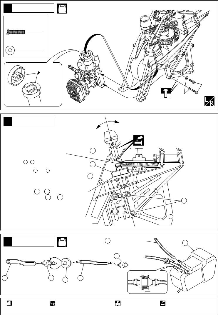
15 Muffler |
NE-9 |
|
|
||
402 |
401 |
|
|||
|
|
|
|
||
4×5mm |
533 |
|
398 |
|
|
|
|
|
|||
Screw |
|
4mm |
|
|
|
|
1 |
|
|
|
|
4×14mm |
|
|
399 |
|
|
|
|
|
|
||
Cap Screw |
400 |
|
|
|
|
|
1 |
|
397 |
|
|
|
|
|
|
||
3×35mm |
3×118mm |
|
|
|
|
Cap Screw |
|
|
|
||
|
|
|
|
||
|
2 |
4×14mm |
4×5mm |
|
|
3mm |
|
|
|
||
|
|
|
|
||
Nut |
|
|
3×35mm |
|
|
|
2 |
|
|
|
|
4mm |
|
|
|
|
|
Nut |
|
|
|
|
|
|
1 |
|
|
|
|
3×118mm |
|
|
|
|
|
|
Screw |
|
|
|
|
|
1 |
|
|
|
3mm |
|
|
|
|
|
|
16 Control Lever |
NE-4 |
|
|
|
|
3×20mm TP |
|
|
|
|
|
|
Screw |
|
|
|
|
|
1 |
|
|
|
|
3×8mm |
|
|
|
30 |
|
|
Washer |
|
|
|
|
|
|
|
|
||
|
1 |
|
|
37 |
36 |
|
|
|
|
|
|
37 |
|
|
|
3×8mm |
|
Aileron Lever Collar |
|
|
|
||
|
|
|
|
||
|
1 |
|
|
|
3×20mm |
|
|
|
|
|
|
|
|
Part bags used. |
Assemble left and right sides the same way. |
11
|
|
NE-5, NE-12 |
|
|
|
|
17 Frame |
|
|
|
|
||
|
|
|
|
|
||
3×15mm TP |
|
|
|
|
|
|
|
Screw |
|
|
|
|
|
|
4 |
|
|
|
|
|
3×25mm TP |
|
395 |
|
|
|
|
|
|
|
|
|
||
|
Screw |
|
|
|
|
|
|
2 |
|
|
|
|
|
|
|
|
|
|
|
3×15mm |
|
|
|
|
|
3×15mm |
3×25mm |
|
|
|
|
|
|
|
|
|
NE-1, NE-2 |
|
|
|
|
18 Rotor Head |
|
|
358 |
|
||
|
|
|
3×10mm |
|||
|
|
|
|
|
|
|
2×8mm |
351 5×8mm |
|
|
352 |
||
|
|
|
||||
|
RT/H Screw |
|
Plastic Bushing |
|
|
|
|
2 |
|
2 |
|
352 |
|
|
|
|
3×10mm |
351 |
2×8mm |
|
3×10mm TP |
|
|
||||
|
|
|
|
|
||
|
Screw |
212 |
|
|
|
|
|
2 |
|
Linkage Ball |
|
|
|
|
|
|
|
|
|
|
|
|
|
2 |
212 |
|
212 |
352 3×5mm |
|
|
|
|||
|
|
2×8mm |
|
|
||
Collar |
|
|
|
|
||
|
|
|
|
|
||
2 |
|
|
|
351 |
350 |
||
Note the direction. |
|||
|
|
|
|
|
|
|
|
3×4mm |
|
|
|
|
|
|
|
|
|
||
19 Rotor Head |
|
NE-1, NE-13 |
|
|
|
|
||
3×4mm |
|
|
|
|
|
|
|
|
Set Screw |
2 |
|
|
|
|
436 |
|
|
|
|
|
|
|
|
|
|
|
4×5mm |
|
|
|
|
5 |
|
4×5mm |
|
Set Screw |
|
|
|
|
|
|
||
|
|
|
|
|
|
|
||
|
|
1 |
|
|
|
|
|
|
6 |
|
|
3×4mm |
3 |
|
|
2 |
|
|
Hiller Control Lever Bushing |
|
|
|
|
|
|
|
|
|
1 |
|
|
|
|
1 |
|
|
|
|
|
|
|
|
|
|
436 |
3mm |
|
|
|
4 |
4 |
|
7 |
|
|
|
|
|
|
|||
|
|
|
|
|
|
|
||
|
Stopper |
|
|
|
|
|
6 |
|
|
|
|
|
436 |
|
|
|
|
|
|
2 |
|
|
|
|
|
|
|
|
|
|
|
|
Note the direction. |
|
|
|
|
|
|
|
|
|
||
Part bags used. |
Assemble left and right |
Tentatively tighten. |
Assemble in the specified |
Apply threadlocker |
Apply grease. |
|
sides the same way. |
|
order. |
(screw cement). |
|
12
|
|
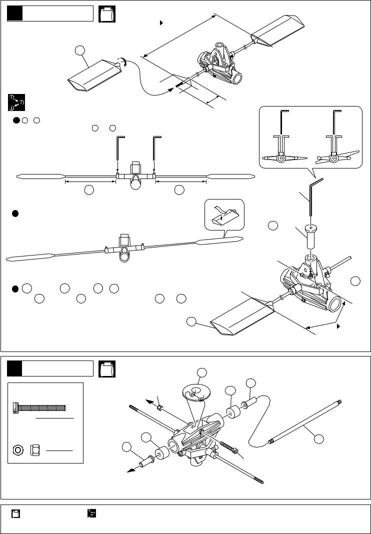
20 Rotor Head |
NE-1 |
|
|
|
Parallel |
|
148 |
|
30mm |
|
|
|
About 30mm |
|
× |
1 A Ð A ' |
|
||
|
|
|
|
Tighten the set screws when A and A ' are equally long. |
|
|
|
A  A '
A '
2
To balance left and right ends, place a piece of tape to the lighter end.
3417 7 7 148
Hold 7 in place with 417 . Tighten the set screw when 7 and 148 are parallel.
2mm Hex Wrench 2mm
417
( jig )


 7
7
|
|
|
148 |
|
|
|
|
|
|
|
Parallel |
|
|
|
|
21Rotor Head |
|
NE-1 |
357 |
|
|
|
354 |
3×25mm |
|
3mm |
536 |
Cap Screw |
|
|
|
|
|
|
|
|
1 |
|
|
3mm |
|
|
|
Nylon Nut |
|
536 |
355 |
|
1 |
354 |
|
|
|
|
|
|
|
|
3×25mm |
|
|
|
|
|
|
|
Part bags used. |
Assemble in the specified order. |
13

cm 0 
 1
1
 2
2
 3
3
 4
4
5
6
7
8
9
10 11 12 13 14
|
|
|
|
|
|
|
|
22 Rotor Head |
|
NE-1, NE-2 |
|
|
353A |
|
x2 |
|
|
2×10mm |
|
|
|
||
|
|
|
212 |
|
|
56 |
|
2×10mm |
16 |
5×7mm |
|
|
|
17 |
|
|
|
|
|
|
|||
RT/H Screw |
|
Spacer |
|
|
|
|
16 |
2 |
|
2 |
|
|
|
|
56 |
|
|
|
|
|
|
||
3×6mm TP |
|
|
|
|
|
|
|
Screw |
17 |
10×13mm |
|
|
|
|
|
4 |
|
Spacer |
|
|
|
|
|
4mm |
|
2 |
|
|
|
|
3×6mm |
Nylon Nut |
|
|
|
|
|
|
|
2 |
56 5×13mm |
|
|
|
|
|
|
|
|
Ball Bearing |
|
|
|
|
|
212 |
|
|
|
|
|
|
|
Linkage Ball |
|
4 |
|
|
4mm |
|
|
2 |
|
|
|
|
|
|
|
|
|
|
|
|
|
|
|
|
|
NE-12, NE-13 |
|
|
|
|
|
23 Tail Boom |
|
|
|
|
|
|
|
|
|
|
|
|
|
|
|
|
|
405 |
403 |
|
|
|
|
|
|
|
|
|
|
|
|
408 |
|
|
177 |
|
|
|
|
|
|
|
|
|
|
|
|
|
|
235 |
|
|
|
|
|
|
|
|
factory - inserted |
|
|
|
|
|
|
|
●403 |
|
|
|
|
403 |
|
|
Positioning |
403 |
|
|
|
|
|
|
|
|
|
|
|
|
|
404 |
|
|
|
|
|
|
|
|
|
220mm |
|
|
120mm |
25 24 23 22 21 20 19 18 17 16 15
|
NE-2, NE-10 |
537 |
79 |
|
|
24 Tail Gearbox |
|
Pass 79 through this hole. |
|||
|
|
|
|||
2.6×8mm |
|
|
1 |
|
|
83 5×10mm |
|
80 |
|
||
Screw |
|
|
|||
|
Ball Bearing |
|
83 |
|
|
|
|
|
|||
|
1 |
|
|
84 |
79 |
2.6×14mm |
|
2 |
|
|
|
|
|
|
|
2 |
|
Screw |
|
|
|
|
|
|
|
|
|
78 |
|
|
2 76 8×14mm |
2.6×8mm |
|
3 |
|
3×4mm |
|
Ball Bearing |
|
|
|
|
|
2.6×14mm |
|
|
|
Set Screw |
|
|
|
|
|
|
|
|
|
3×4mm |
|
|
1 |
2 |
|
83 |
|
|
|
|
|||
|
|
|
|
|
|
4×5mm |
|
|
|
|
|
Set Screw |
|
|
4×5mm |
|
|
|
1 |
|
|
|
|
|
|
|
|
|
|
2.6mm |
|
|
|
77 |
|
Nut |
|
|
76 |
|
|
|
|
|
|
||
|
|
|
|
|
|
|
3 |
|
|
|
|
|
|
|
75 |
|
|
79 2×12mm |
|
|
▲D |
81 |
2.6mm |
Pin |
|
|
|
|
|
1 |
|
|
|
|
|
|
|
|
|
||
|
|
|
Flat end of shaft |
|
|
|
|
x2 |
|
|
|
|
|||||
Part bags used. |
Assemble left and right |
Apply threadlocker |
Assemble as many times as |
Assemble in the |
Apply grease. |
|
sides the same way. |
(screw cement). |
specified (here: twice). |
specified order. |
|
14
 Loading...