


Before commencing assembly, please read these instructions thoroughly.
R
WINGSPAN: 1500mm (59")
THE FINEST RADIO CONTROL MODELS
INSTRUCTION MANUAL
For
Advanced Flyers
D
e
|
|
|
|
|
01 |
|
|
|
|
0 |
|
|
|
|
2 |
|
|
|
|
y |
|
|
|
|
|
b |
|
|
|
|
|
d |
|
|
|
|
e |
|
|
|
|
n |
|
|
|
|
|
ig |
|
|
|
|
|
s |
|
|
|
|
|
F3A
World
Ch a m p i o
n
3D 40
Christophe Paysant-Le Roux
F L I P 3D 40
RADIO CONTROLLED .40-CLASS ENGINE POWERED ALL-BALSA SLOW ACROBATIC 3D AIRCRAFT
INDEX |
|
● |
2 |
REQUIRED FOR OPERATION |
|
● |
3 |
BEFORE YOU BEGIN |
|
● |
3~11 |
ASSEMBLY |
|
● |
12 |
SPARE PARTS / OPTIONAL PARTS |
|
● |
12 / 15 |
OPERATING YOUR MODEL SAFELY |
|

!
●
●
●
●
SAFETY PRECAUTIONS
This radio control model is not a toy!
●First-time builders should seek the advice of experienced modellersbefore commencing assembly and if they do not fully understandany part of the construction.
●Assemble this kit only in places out of children’s reach! ●Take enough safety precautions prior to operating this model.
You are responsible for this model’s assembly and safe operation! ●Always keep this instruction manual ready at hand for quick reference,
even after completing the assembly.
SPECIFICATIONS ARE SUBJECT TO CHANGE WITHOUT NOTICE. |
No.11141 |
© 2001 KYOSHO

REQUIRED FOR OPERATION (Not included in kit!)
|
|
|
CAUTION: For details concerning the equipment listed below |
|
(size, maker, etc.), check with your hobby shop. |
1 4 5 x 5
A minimum 4 channel radio for airplanes (with 5 standard servos), and nicad or alkaline batteries are required.
( )(4 ) ( )
 CAUTION: Only use a minimum 4 channel radio for aircraft!(No other radio may be used!)
■4
A minimum 4 channel transmitter for aircraft with 5 servos.
■ …2
2 aileron extension cords 
For handling the radio properly, refer to its instruction manual.
2 |
|
|
|
Engine and Muffler |
|
|
|
|
■ |
|
|
|
Model Airplane Engine |
|
|
|
2 4650 |
|
|
|
2-stroke .46~.50 |
|
|
|
4 5063 |
|
|
|
4-stroke .50~.63 |
|
■ |
|
|
|
|
|
■ |
Muffler |
|
|
|
Glow Plug |
|
|
|
|
|
*Do not use more powerful engine above.
3 |
|
■ |
Propeller and Spinner |
Propeller |
Purchase a propeller thatwill match your engine.
■ |
■ |
■PP |
|
PP Pipe |
|||
4 Sponge Sheet |
Fuel line |
||
( 2.3mm) |
5
Required for engine starting:
■
Glow engine fuel only.
|
|
|
|
M O DEL |
|
WARNING: Normal gasoline |
|
E N G IN |
E |
|
cannot be used with |
|
|
||
F UEL |
|
glow engines. |
|
|
|
|
|
|
|
|
■ |
■ |
|
One-touch Plug Heater Set |
|
Fuel Primer |
|
||
|
|
||
■Plug Wrench
6 Glue
■ |
■ (30) |
Instant Glue |
Epoxy Glue (30 minutes type) |
|
Epoxy A |
|
Epoxy B |
■ |
|
Silicon Glue |
SILICON |
7
Other equipment for enhancing airplane operation & performance
■ |
■12V |
Engine Starter |
12V Battery (for starter) |
|
|
|
|
■ |
|
|
Fuel Filter |
■ ( ) |
|
|
Polyurethane paint (Clear) |
|
|
A |
B |
■ |
|
|
Spinner(57mm |
|
|
TOOLS REQUIRED (Purchase separately!)
■ |
■ |
■ |
|
Scissors |
Awl |
||
Sharp Hobby Knife |
|||
|
|
||
|
|
■ |
|
■ |
■ |
Phillips Screwdriver (L, M, S) |
|
Needle Nose Pliers |
Wire Cutters |
|
|
|
|
■ |
|
|
|
Drill, Handgrinder |
2
BEFORE YOU BEGIN
1
Read through the manual before you begin, so you will have an overall idea of what to do.
2
Check all parts. If you find any defective or missing parts, contact your local dealer or our Kyosho Distributor.
3
Symbols used throughout this instruction manual, comprise:
|
|
|
|
|
|
2mm |
|
|
|
|
|||||
|
2mm |
|
Drill holes with the specified |
||||
Apply epoxy glue. |
|
|
|||||
|
|
diameter (here: 2mm). |
|||||
|
|
|
|||||
|
|
|
|
|
|
|
|
Apply instant glue |
|
|
|
|
|
|
|
|
|
|
|
|
|
|
|
|
|
|
|
|
Cut off shaded portion. |
||
(CA glue, super glue). |
|
|
|
|
|
||
|
|
|
|
|
|
|
|
|
|
|
|
|
|
||
Assemble left and right |
|
|
|
|
|||
|
|
|
|
Must be purchased separately! |
|||
sides the same way. |
|
|
|
|
|||
|
|
|
|
|
|
||
Cut off excess.
Ensure smooth non-binding movement while assembling.

Pay close attention here!
●
Do not overlook thissymbol!
 Warning!
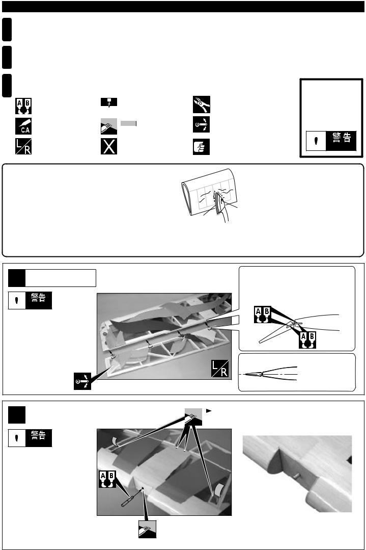
The pre-covered film on ARF kits may wrinkledue to variations of temperature. Smooth out as explained here.
 with cover (cloth)
lowsetting

 Use an iron covered with a cloth! Start at low setting. Increase the set-- ting if necessary. If it is too high, you may damage the film.
You can keep the covering film from wrinkling or peeling by spraying the plane with clear polyurethane.
1
Main Wing
 Warning!

Securely glue together. If it comes off during flights, you may lose control of your airplane, resulting in an accident !
 Metal Hinge
Apply Epoxy glue on Metal Hinge, and install completely.

Align the center line of main wing with aileron.
2 |
|
|
|
|
|
|
|||
Main Wing |
|
|
Cut away covering film only. |
|
Bottom view. |
|
|
||
|
|
|
|
|
|
|
|
|
 Warning!

Securely glue together. If it comes off during flights, you may lose control of your airplane, resulting in an accident !

Cut away covering film only.
3
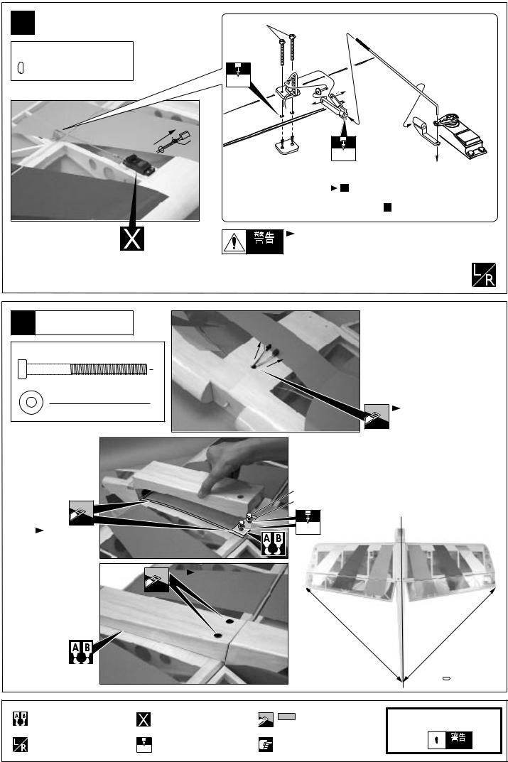
3 |
( |
2 x 20mm |
|
Main Wing(Bottom View) |
|||
|
2 x 20mm Screw


 4
4
2mm
|
|
|
2mm |
|
|
|
17 |
|
|
|
Adjust the travel of each control surface. |
|
|
|
Please refer 17 . |
|
|
|
|
|
Aileron Servo |
Warning! |
|
|
|
Securely glue together. If it comes off during flights, |
|
|
|
|
|
|
|
|
you may lose control of your airplane, resulting |
|
|
|
in an accident ! |
4 |
|
|
|
Main Wing |
|
Top View |
4 x 45mm |
|
|
|
|
Cap Screw |
|
|
|
|
2 |
|
4mm |
|
|
|
Washer |
|
|
|
|
|
2 |
|
|
|
|
|
|
|
|
Cut away film only. |
|
|
|
|
Bottom View |
|
|
|
|
|
|
4 x 45mm |
|
|
|
4mm |
|
|
4.2mm |
|
Cut away film |
|
|
|
only. |
|
|
|
|
|
|
|
Bottom View |
|
||
|
Cut away film |
||
|
|
|
|
|
|
|
only, here. |
A A′
 A = A′
Apply epoxy glue.
Assemble left and right sides the same way.
Must be purchased separately!
 2mm
2mm

 Drill holes with the specified 2mm diameter (here: 2mm).
Cut off shaded portion.
Pay close attention here!
●
Do not disregard this symbol!
 Warning!
4

5 |
|
●2 |
4mm |
|
Engine Mount |
When using a 2 stroke engine. |
|||
4 x 20mm |
|
|
|
|
A 2 A 2 |
|
|
||
|
Cap Screw |
|
||
|
|
4 |
Engine shaft line |
|
|
|
|
|
|
4mm |
|
|
|
|
|
Mount Nut |
5mm |
15mm |
|
|
|
|
||
|
|
4 |
|
|
|
|
23mm |
4 x 20mm |
|
|
|
|
|
|
●4
When using a 4 stroke engine.
Engine shaft line
A |
5mm |
A 2 |
A 2 |
||
|
23mm |
4 x 20mm |
●4
When using a 4 stroke engine with pump.
Engine shaft line
|
A 2 |
5mm |
A 2 |
5mm
4 x 20mm
4mm
4mm
6
Fuel Tank
3 x 35mm TP |
1 |
TP Screw |

After confirming the direction- (see front view of fuel tank), insert and tighten the screw.
●2/4
When using a normal 2 / 4 stroke engine.
3 x 35mm
5mm Sillicon tube 
●4
When using a 4 stroke engine with pump.
3 x 35mm
5mm
Sillicon tube
|
|
|
|
2mm |
|
2mm |
Drill holes with the specified |
||||
Must be purchased separately! |
|||||
diameter (here: 2mm). |
|||||

Pay close attention here!
5
 Loading...