

Page 1
2008 ACCESSORIES & BODY, CAB
Body (Interior & Exterior) - General - Sedona
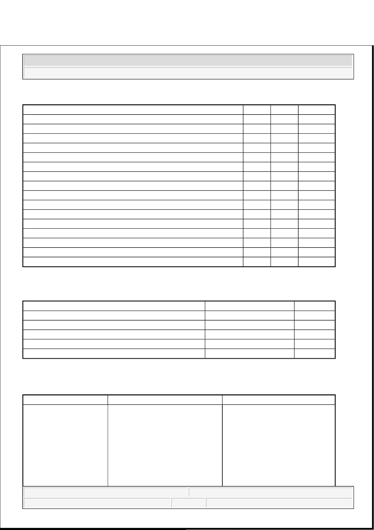
SPECIFICATIONS
GENERAL SPECIFICATIONS
TIGHTENING TORQUE
TIGHTENING TORQUE SPECIFICATIONS
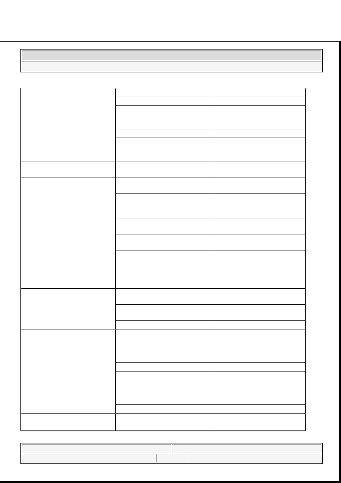
HOOD Type Rear hinged, gas lifter type
FRONT DOOR Construction Front hinged, full door
construction
Regulator system X-ARM type
Locking system Pin-fork system
REAR DOOR Construction Sliding door construction
Regulator system Wire drum type
Locking system Pin-fork system
TAILGATE Type Inner hinged, gas lifter type
GLASS THICKNESS Windshield glass 5 mm
Front door glass 4 mm
Rear door glass 4 mm
Rear window glass 3.5 mm
SEAT BELTS Front 3 point type with Emergency
Locking Retractor (ELR)
Rear 3 point type with Emergency
Locking Retractor (ELR)
Items N.m Kgf. m Lbf. ft
Front and rear doors Door hinge to body 33.3-41.2 3.4-4.2 24.6-30.4
Door hinge to door 21.6-26.5 2.2-2.7 15.9-19.5
Striker 6.9-10.8 0.7-1.1 5.1-8.0
Glass mounting bolt 7.8-11.8 0.8-1.2 5.8-8.7
Outside handle
mounting bolt
6.9-10.8 0.7-1.1 5.1-8.0
Rear channel
mounting nut
7.8-11.8 0.8-1.2 5.8-8.7
Tailgate Tailgate hinge to
body
6.9-8.8 0.7-0.9 5.1-6.5
Tailgate hinge to
tailgate
6.9-8.8 0.7-0.9 5.1-6.5
Tailgate lift
mounting bolt
6.9-8.8 0.7-0.9 5.1-6.5
2008 Kia Sedona EX
2008 ACCESSORIES & BODY, CAB Body (Interior & Exterior) - General - Sedona
2008 Kia Sedona EX
2008 ACCESSORIES & BODY, CAB Body (Interior & Exterior) - General - Sedona
Microsoft
Monday, May 24, 2010 4:05:08 PM Page 1 © 2006 Mitchell Repair Information Company, LLC.
Microsoft
Monday, May 24, 2010 4:05:11 PM Page 1 © 2006 Mitchell Repair Information Company, LLC.
Page 2
SPECIAL TOOLS
SPECIAL TOOLS REFERENCE CHART
Key cylinder
mounting nut
6.9-10.8 0.7-1.1 5.1-8.0
Hood Hood hinge to body 21.6-26.5 2.2-2.7 15.9-19.5
Hood hinge to hood 21.6-26.5 2.2-2.7 15.9-19.5
Hood latch to body 6.9-10.8 0.7-1.1 5.1-8.0
Seat Front seat mounting
bolts
43.1-64.7 4.4-6.6 31.8-47.7
Rear seat mounting
bolts
43.1-64.7 4.4-6.6 31.8-47.7
Seat belt Front seat belt
height adjuster
39.2-53.9 4.0-5.5 28.9-39.8
Front seat belt
buckle mounting
bolt
39.2-53.9 4.0-5.5 28.9-39.8
Front seat belt
anchor mounting
bolt
39.2-53.9 4.0-5.5 28.9-39.8
Front seat belt lower
anchor
39.2-53.9 4.0-5.5 28.9-39.8
Front seat belt upper
anchor
39.2-53.9 4.0-5.5 28.9-39.8
Rear seat belt
anchor attaching
bolt
39.2-53.9 4.0-5.5 28.9-39.8
Rear seat belt
retractor mounting
bolt
39.2-53.9 4.0-5.5 28.9-39.8
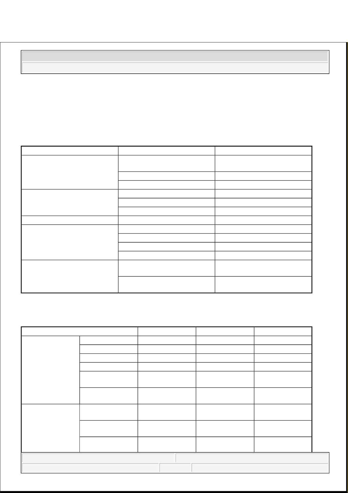
Tool (Number and name) Illustration Use
09793-2100
Door hinge adjusting wrench
Adjustment, removal and
installation
Of the door hinge
09800-21000
Ornament remover
Trim removal
2008 Kia Sedona EX
2008 ACCESSORIES & BODY, CAB Body (Interior & Exterior) - General - Sedona
Microsoft
Monday, May 24, 2010 4:05:08 PM Page 2 © 2006 Mitchell Repair Information Company, LLC.
Page 3
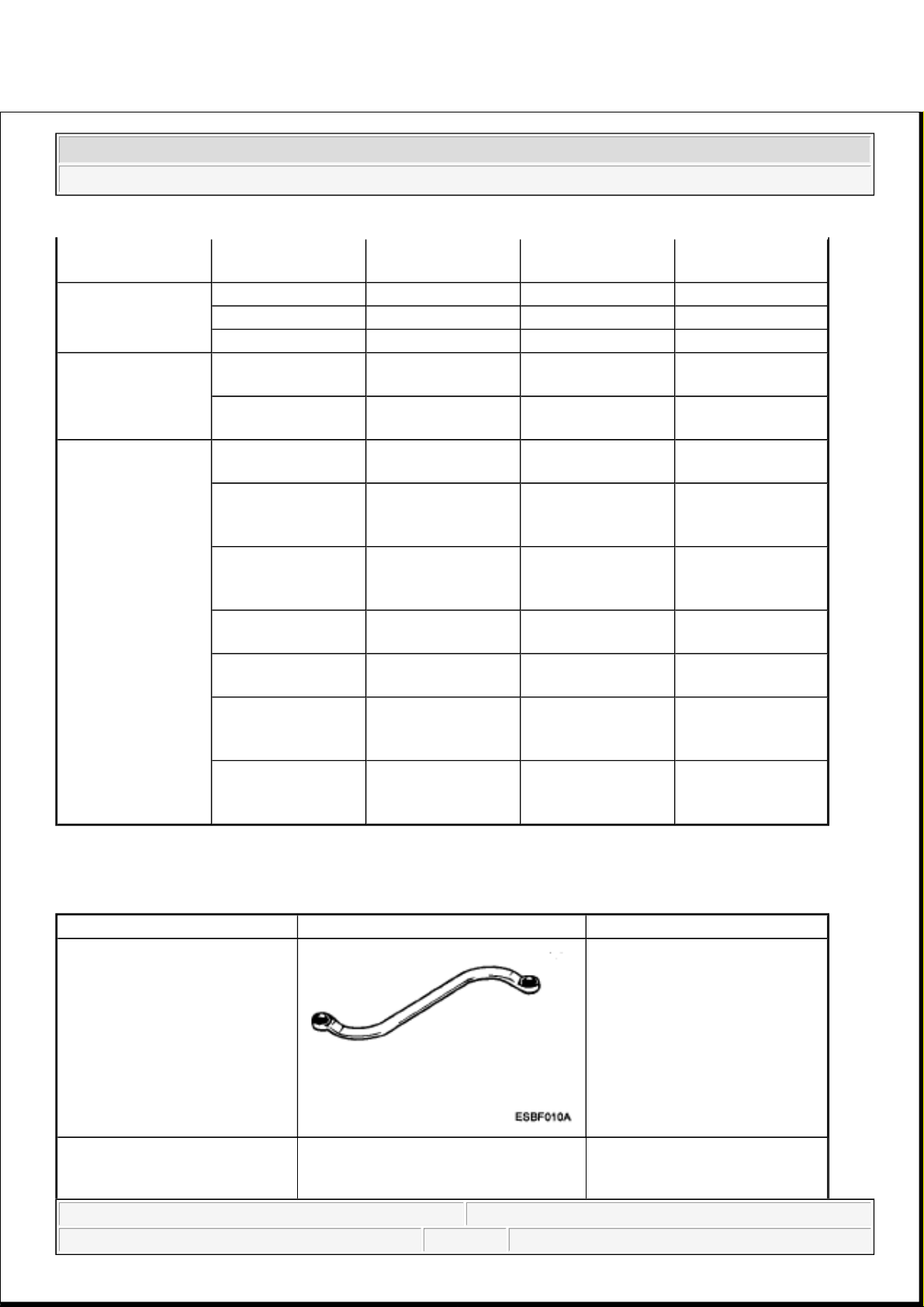
09853-31000
Headliner clip remover
Removal of the headliner clips
09861-31100
Sealant cut-out tool
Cutting the sealant of the
windshield
(Use with 09861-31200)
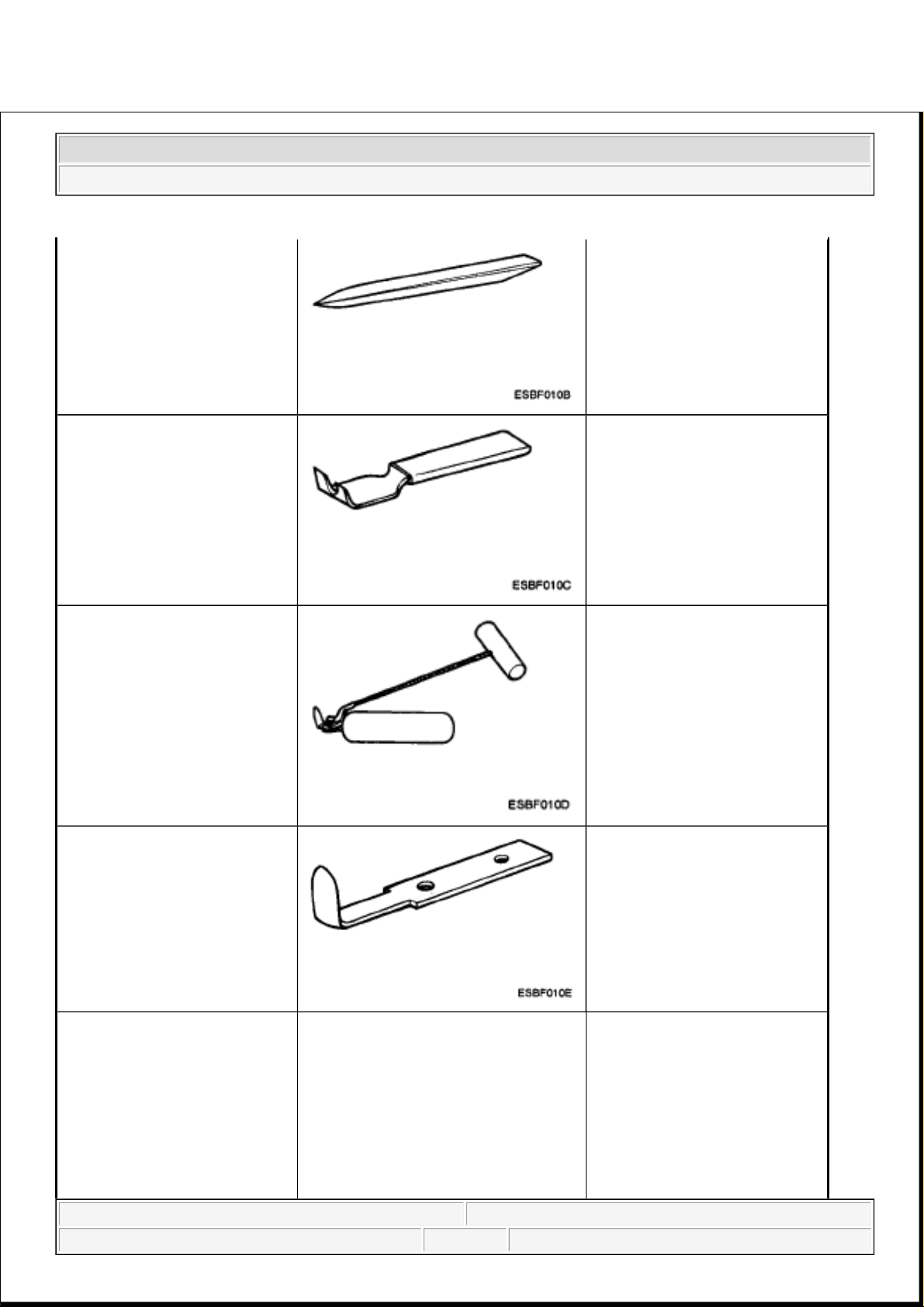
09861-31200
Sealant cutting blade
Cutting the sealant of the
windshield
(Use with 09861-31100)
09861-31300
Sealant gun
Application of the sealant to the
windshield
2008 Kia Sedona EX
2008 ACCESSORIES & BODY, CAB Body (Interior & Exterior) - General - Sedona
Microsoft
Monday, May 24, 2010 4:05:08 PM Page 3 © 2006 Mitchell Repair Information Company, LLC.
Page 4
TROUBLESHOOTING
TROUBLESHOOTING CHART
09681-31400
Glass holder
Removal and installation of the
windshield
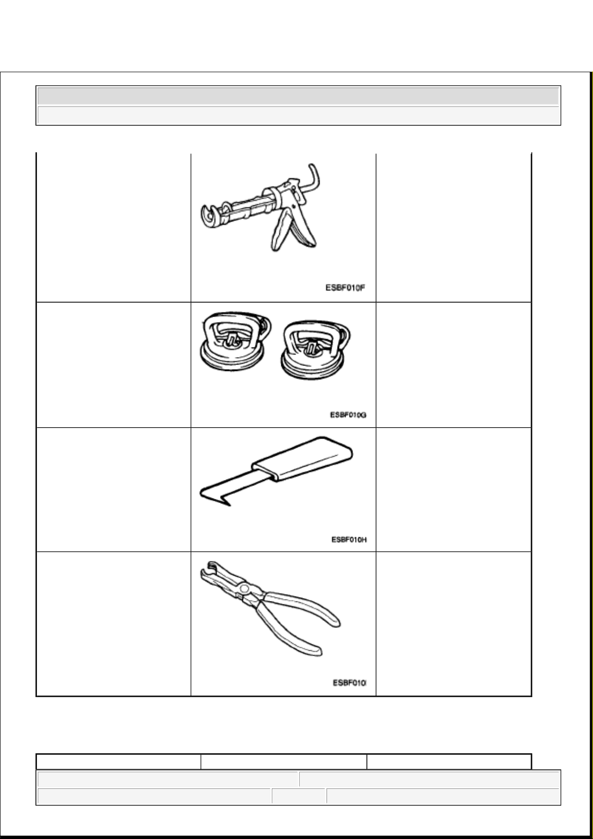
09681-31000
Windshield molding remover
Removal of the windshield
molding
09880-4F000
Hog ring clip installer
Installation of the hog ring clip
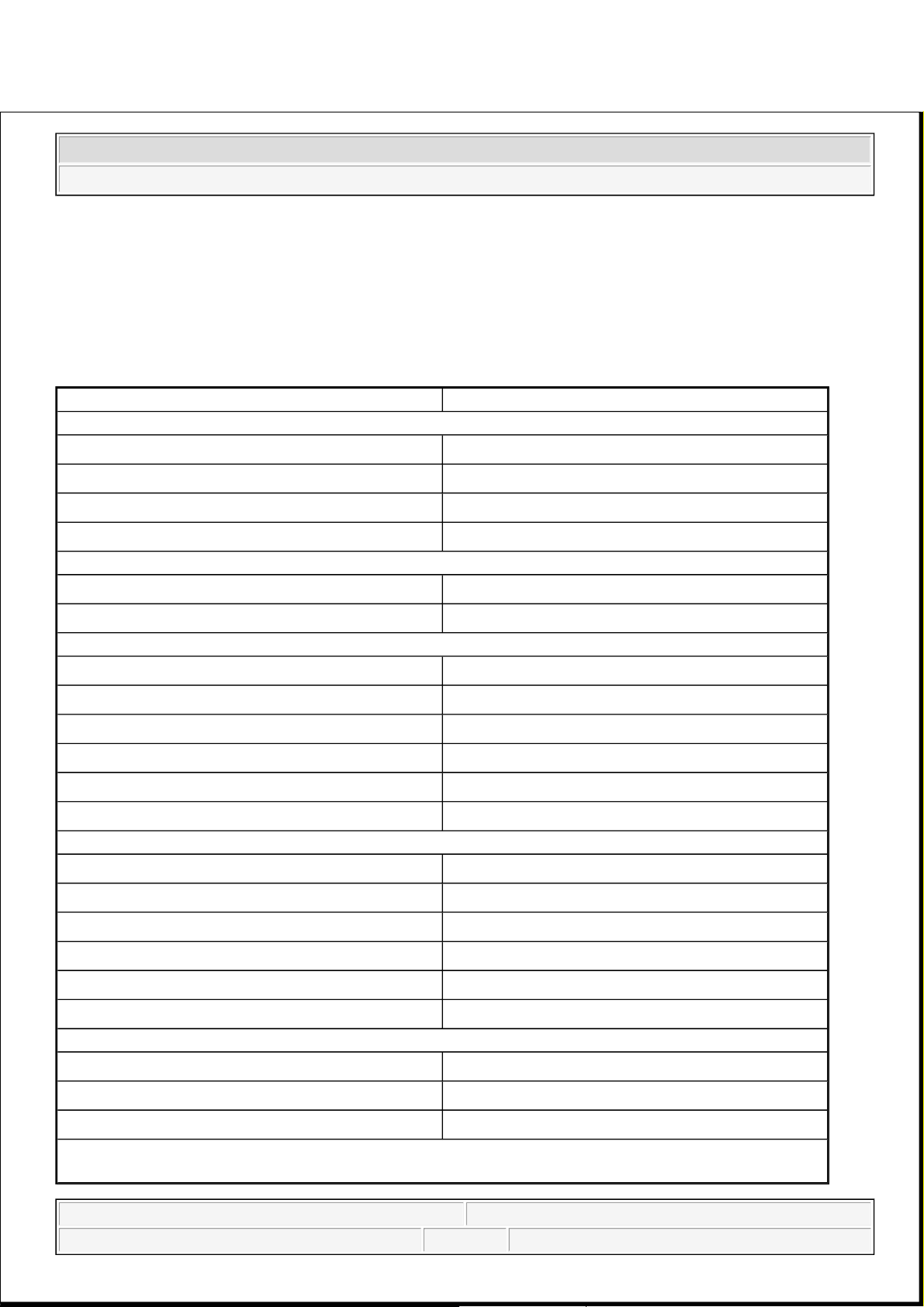
Symptom Suspect Area Remedy
2008 Kia Sedona EX
2008 ACCESSORIES & BODY, CAB Body (Interior & Exterior) - General - Sedona
Microsoft
Monday, May 24, 2010 4:05:08 PM Page 4 © 2006 Mitchell Repair Information Company, LLC.
Page 5
Water leaks from sunroof Dirt accumulated in drain tube Clear dirt inside of drain
Clogged drain tube Blow air into drain to remove dirt
Broken or dislocated drain tube,
defective
Or cracked clip
Check tube installation and Flange
contact
Deteriorated roof lid weatherstrip Replace
Excessive roof lid-to-body
clearance and Improperly fitted
weatherstrip
Adjust
Wind noise around sunroof Loose or deformed deflector, gaps
In body work
Retighten adjust or replace
Sunroof lid makes a noise when
moving
Foreign particles lodged in guide
rail
Check drive cable and guide Rails
for foreign particles
Loose guide rails and lid Retighten
Motor runs but sunroof does not
move or moves only partially
Foreign particles lodged in guide
rail
Check drive cable and guide Rails
for foreign particles
Incorrect engagement of motor
pinion With drive cable
Check for loose motor installation
And damaged pinion
Decrease in motor's clutch slipping
force
Adjust
Increased sunroof sliding
resistance Or interference of
sunroof with drive cables,
weatherstrip, etc. due to
maladjustment of sunroof
Adjust or replace
Noise in motor (clutch slipping
Noise from motor when sunroof Is
fully opened or closed is not An
unusual noise)
Incorrect engagement of motor
pinion With drive cable
Check pinion installation and
Retighten motor
Worn out or damaged motor
pinion bearing
Replace motor assembly
Worn out or deformed drive cable Replace
Door glass fails to operate Up and
down
Incorrect window glass installation Adjust position
Damaged or faulty regulator arm
or regulator
Correct or replace
Door does not open or close
completely
Incorrect door installation Adjust position
Defective door check assembly Correct or replace
Door hinge requires grease Apply grease
Hood does not open or close
completely
Striker and latch not properly
aligned
Adjust
Incorrectly installed hood Adjust
Incorrect hood bumper height Adjust
Water leak through windshield
end rear window
Defective seal Fill with sealant
Defective flange Correct
2008 Kia Sedona EX
2008 ACCESSORIES & BODY, CAB Body (Interior & Exterior) - General - Sedona
Microsoft
Monday, May 24, 2010 4:05:08 PM Page 5 © 2006 Mitchell Repair Information Company, LLC.
Page 6
2008 BRAKES
Brake System - General - Sedona
SPECIFICATIONS
BRAKE SYSTEM SPECIFICATIONS
Item Specification
Master cylinder
Type
Tandem type
I.D. mm (in)
26.99/(1.063)
Piston stroke mm (in)
30 (1.18)
Fluid level warning sensor
Provided
Brake booster
Type
8 + 9 in Tandem
Boosting ratio
9.0: 1
Front brake (Disc)
Type
Floating type with ventilated disc
Disc O.D.
298 mm (11.73 in)
Disc thickness
28 mm (1.10 in)
Pad thickness
10.5 mm (0.41 in)
Cylinder type
Double piston
Cylinder I.D.
Ø48 mm (Ø1.89 in)
Rear Brake (Disc)
Type
Floating type with solid disc
Disc O.D.
302 mm (11.89 in)
Disc thickness
12 mm (0.47 in)
Pad thickness
10 mm (0.39 in)
Cylinder type
Single piston
Cylinder I.D
Ø42.9 mm (Ø1.69 in)
Parking Brake
Type
DIH (Drum in hat)
Actuation
Foot brake
Drum
Ø190 mm (Ø7.48 in)
O.D=Outer Diameter
I.D=Inner Diameter
2008 Kia Sedona
2008 BRAKES Brake System - General - Sedona
2008 Kia Sedona
2008 BRAKES Brake System - General - Sedona
Microsoft
Saturday, May 22, 2010 6:55:01 PM Page 1 © 2006 Mitchell Repair Information Company, LLC.
Microsoft
Saturday, May 22, 2010 6:55:04 PM Page 1 © 2006 Mitchell Repair Information Company, LLC.
Page 7
SPECIFICATION (ABS)
ANTI-LOCK BRAKE SYSTEM SPECIFICATIONS
SPECIFICATION (ESC)
ELECTRONIC STABILITY CONTROL SPECIFICATIONS
NOTE: ABS: Anti-Lock Brake System
ESC: Electronic Stability Control
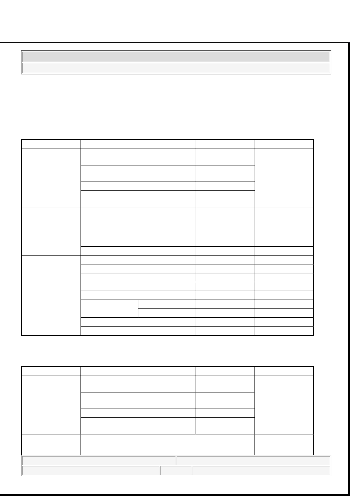
Part Item Standard value Remark
HECU (Hydraulic
and Electronic
Control Unit)
System 4 channel 4 sensor
(Solenoid)
•ABS system: ABS
& EBD control
Type Motor, valve relay
integrated type
Operating voltage 8 V-16 V (DC)
Operating temperature -40 to 120°C (-40 to
248°F)
Warning lamp
Operating voltage 12 V •ABS W/LABS
failure
•Brake W/L:
Parking, brake oil,
EBD failure
Current consumption 80 mA
Active wheel speed
sensor
Supply voltage DC 4.5-2.0 V
Operating temperature -40-150 °C
Output current low 5.9-8.4 mA Typ.7 mA
Output current High 11.8-16.8 mA Typ.14 mA
Frequency range 1-2500 HZ
Air gap
Front 0.15-1.5 mm Typ.0.7 mm
Rear 0.2-1.2 mm Typ.0.7 mm
Tone wheel 48 teeth
Output duty 30-70 %
Part Item Standard Value Remark
HECU (Hydraulic
and Electronic
Control Unit)
System 4 channel 4 sensor
(Solenoid)
•Total control (ABS,
EBD, TCS, ESC)
Type Motor, valve relay
integrated type
Operating voltage 8 V-16 V (DC)
Operating temperature -40 to120°C (-40 to
248°F)
Warning lamp
Operating voltage 12 V •ESC Operating
Lamp
2008 Kia Sedona
2008 BRAKES Brake System - General - Sedona
Microsoft
Saturday, May 22, 2010 6:55:01 PM Page 2 © 2006 Mitchell Repair Information Company, LLC.
Page 8
SERVICE STANDARD
SERVICE STANDARD SPECIFICATIONS
TIGHTENING TORQUE
ESC Warning Lamp
Current consumption 80 mA
Active wheel speed
sensor
Supply voltage DC 4.5-20 V
Operating temperature -40-150 °C
Output current low 5.9-8.4 mA
Output current high 11.8-16.8 mA
Tone wheel 48 teeth
Frequency range 1-2500 HZ
Air gap
Front 0.15-1.5 mm Type. 0.7 mm
Rear 0.2-1.2 mm Type. 0.7 mm
Steering Wheel
Angle Sensor
Operating Voltage 8V-16 V
Current Consumption Max 150 mA
Operating Angular velocity Max ± 780 °/sec
Yaw-rate & Lateral
G sensor
Operating Voltage 8 V-16 V
Current Consumption Max. 120 mA
Output Voltage high 4.35 V-4.65 V Type. 4.5 V
Output Voltage low 0.35-0.65 V Type. 0.5 V
Yaw Sensor Operating Range ±100 ° /s
G Sensor Operating Range ±1.8 G
Reference voltage output 2.464-2.536 V Type. 2.5 V
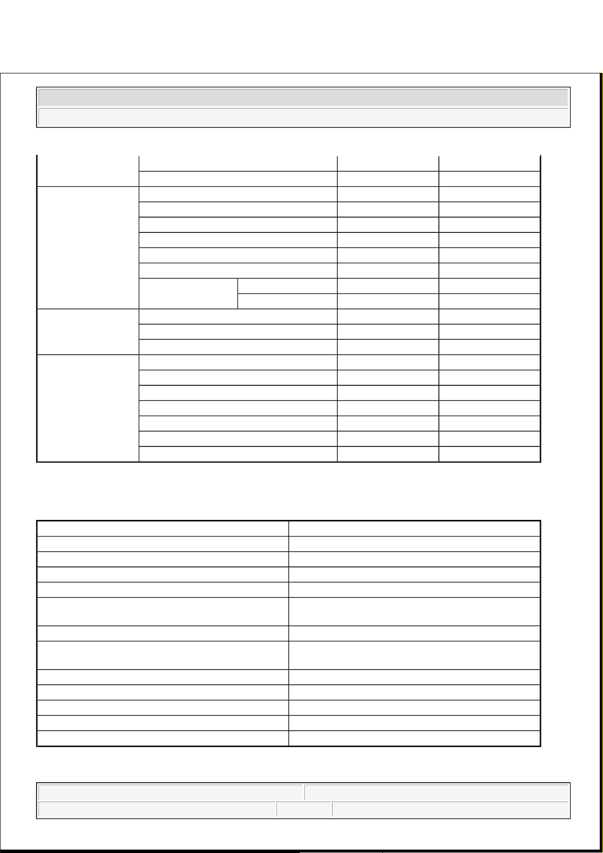
Items Standard value
Brake pedal height 192.4 mm (7.57 in)
Brake pedal full stroke 122 mm (4.8 in)
Adjust Brake pedal full stroke 60 mm (2.36 in)
Brake pedal free play 3-8 mm (0.11-0.31 in)
Stop lamp switch outer case to pedal stopper
clearance
1.0-1.5 mm (0.04-0.06 in)
Booster push rod to master cylinder piston clearance 0.6-1.7 mm (0.02-0.07 in) (at 500 mm.Hg)
Parking brake pedal stroke when pedal assembly is
depressed with 294N (30kgf, 661b force)
145 mm (5.71 in) above
Front disc brake pad thickness 10.5 mm (0.41 in)
Front disc thickness 28 mm (1.10 in)
Rear disc brake pad thickness 10 mm (0.394 in)
Rear disc brake disc thickness 12 mm (0.47 in)
Rear parking brake liner thickness 4 mm (0.16 in)
2008 Kia Sedona
2008 BRAKES Brake System - General - Sedona
Microsoft
Saturday, May 22, 2010 6:55:01 PM Page 3 © 2006 Mitchell Repair Information Company, LLC.
Page 9
TIGHTENING TORQUE SPECIFICATIONS
LUBRICANT
LUBRICANT SPECIFICATIONS
SPECIAL TOOL
SPECIAL TOOLS DESCRIPTION
Items N.m kgf.m lb-ft
Master cylinder to booster mounting nut 8-12 0.8-1.2 5.8-8.7
Brake booster mounting nut 13-16 1.3-1.6 9.4-11.6
Bleeder screw 7-13 0.7-1.3 5.06-9.4
Brake tube nut, brake hose 13-17 1.3-1.7 9.4-12.3
Caliper guide rod bolt (Front) 22-32 2.2-3.2 15.9-23.1
Caliper guide rod bolt (Rear) 22-32 2.2-3.2 15.9-23.1
Caliper assembly to knuckle (Front) 85-100 8.5-10 61.5-72.3
Caliper assembly to knuckle (Rear) 50-60 5.0-6.0 36.2-43.4
Brake hose to front caliper 25-30 2.5-3.0 18.1-21.7
Brake pedal assembly bracket mounting nut 10-15 1.0-1.5 7.2-10.8
Brake pedal mounting nut 13-16 1.3-1.6 9.4-11.6
Stop lamp switch mounting nut 8-10 0.8-1.0 5.8-7.2
Active wheel speed sensor mounting bolt on the brake plate 7-10 0.7-1.0 5.1-7.2
HECU mounting bracket bolt 17-26 1.7-2.6 12.3-18.8
HECU mounting nut 6-10 0.6-1.0 4.3-7.2
Yaw rate & lateral acceleration sensor bolt 5-8 0.5-0.8 3.6-5.8
Item Recommended lubricant Quantity
Brake fluid DOT 3 or DOT 4 As required
Brake pedal bushing and brake pedal bolt Chassis grease As required
Parking brake shoe and backing plate contact surfaces Bearing grease As required
Caliper guide rod and boot RX - 2 grease 0.8-1.3 g
Rear caliper guide rod and boot Rubber grease 0.8-1.3 g
Tool (Number and Name) Illustration Use
09581-11000
Piston expander
Spreading the front disc brake piston
2008 Kia Sedona
2008 BRAKES Brake System - General - Sedona
Microsoft
Saturday, May 22, 2010 6:55:01 PM Page 4 © 2006 Mitchell Repair Information Company, LLC.
Page 10

TROUBLESHOOTING
PROBLEM SYMPTOMS TABLE
Use the table below to help you find the cause of the problem. The numbers indicate the priority of the like
cause of the problem. Check each part in order. If necessary, replace these parts
TROUBLESHOOTING CHART
Symptom Suspect Area Reference
Lower pedal or spongy pedal 1. Brake system (Fluid leaks) repair
2. Brake system (Air in) air-bleed
3. Piston seals (Worn or damaged) replace
4. Rear brake shoe clearance (Out
of adjustment)
adjust
5. Master cylinder (Inoperative) replace
Brake drag 1. Brake pedal freeplay
(Minimum)
adjust
2. Parking brake lever travel (Out
of adjustment)
adjust
3. Parking brake wire (Sticking) repair
4. Rear brake shoe clearance (Out
of adjustment)
adjust
5. Pad or lining (Cracked or
distorted)
replace
6. Piston (Stuck) replace
7. Piston (Frozen) replace
8. Anchor or Return spring
(Inoperative)
replace
9. Booster system (Vacuum leaks) repair
10. Master cylinder (Inoperative) replace
Brake pull 1. Piston (Sticking) replace
2. Pad or lining (Oily) replace
2008 Kia Sedona
2008 BRAKES Brake System - General - Sedona
Microsoft
Saturday, May 22, 2010 6:55:01 PM Page 5 © 2006 Mitchell Repair Information Company, LLC.
Page 11

3. Piston (Frozen) replace
4. Disc (Scored) replace
5. Pad or lining (Cracked or
distorted)
replace
Hard pedal but brake inefficient 1. Brake system (Fluid leaks) repair
2. Brake system (Air in) air-bleed
3. Pad or lining (Worn) replace
4. Pad or lining (Cracked or
distorted)
replace
5. Rear brake shoe clearance (Out
of adjustment)
adjust
6. Pad or lining (Oily) adjust
7. Pad or lining (Glazed) replace
8. Disc (Scored) replace
9. Booster system (Vacuum leaks) repair
Noise from brake 1. Pad or lining (Cracked or
distorted)
replace
2. Installation bolt (Loosen) adjust
3. Disc (Scored) replace
4. Sliding pin (Worn) replace
5. Pad or lining (Dirty) clean
6. Pad or lining (Glazed) replace
7. Anchor or Return spring
(Inoperative)
replace
8. Brake pad shim (Damage) replace
9. Shoe hold-down spring
(Damage)
replace
Brake fades 1. master cylinder replace
Brake vibration, pulsation
1. brake booster replace
2. pedal free play adjust
3. master cylinder replace
4. caliper replace
5. master cylinder cap seal replace
6. damaged brake lines replace
Brake Chatter
Brake chatter is usually caused by
loose or worn components, or
glazed or burnt linings. Rotors
with hard spots can also contribute
to brake chatter. Additional causes
of chatter are out-of-tolerance
rotors, brake lining not securely
attached to the shoes, loose wheel
bearings and contaminated brake
lining.
2008 Kia Sedona
2008 BRAKES Brake System - General - Sedona
Microsoft
Saturday, May 22, 2010 6:55:01 PM Page 6 © 2006 Mitchell Repair Information Company, LLC.
Page 12
2008 ELECTRICAL
Charging System - Sedona
DESCRIPTION
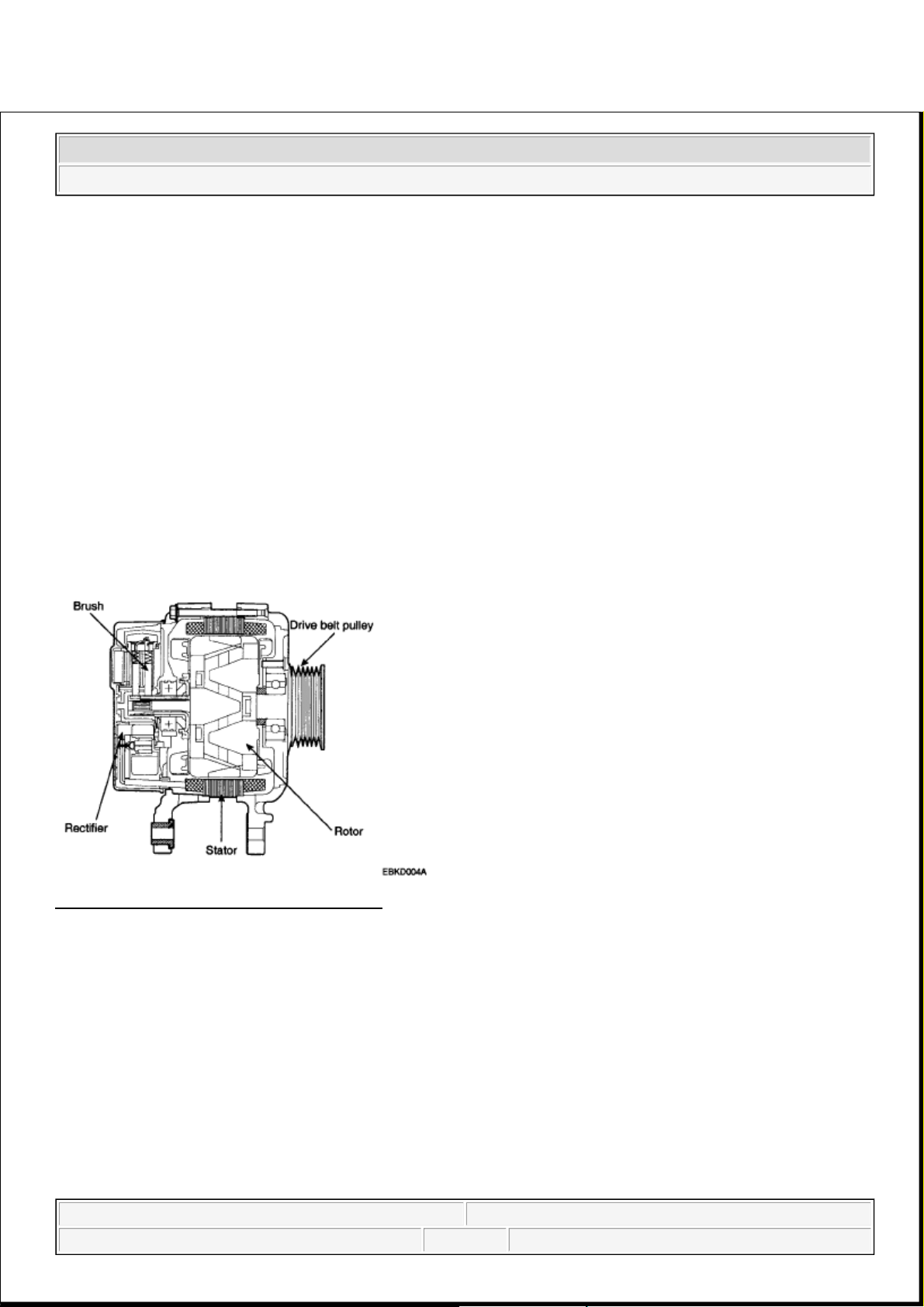
The charging system includes a battery, an generator with a built-in regulator, and the charging indicator light
and wire.
The Generator has built-in diodes, each rectifying AC current to DC current.
Therefore, DC current appears at generator "B" terminal. In addition, the charging voltage of this generator is
regulated by the battery voltage detection system.
The main components of the generator are the rotor, stator, rectifier, capacitor brushes, bearings and V-ribbed
belt pulley. The brush holder contains a built-in electronic voltage regulator.
Fig. 1: Identifying Generator Components
Courtesy of KIA MOTORS AMERICA, INC.
ON-VEHICLE INSPECTION
CHECK BATTERY VOLTAGE
1. If 20 minutes have not passed since the en
g
ine was stopped, turn the ignition switch ON and turn on the
CAUTION:
Check that the battery cables are connected to the correct terminals.
Disconnect the battery cables when the battery is given a quick
charge.
Never disconnect the battery while the engine is running.
2008 Kia Sedona
2008 ELECTRICAL Charging System - Sedona
2008 Kia Sedona
2008 ELECTRICAL Charging System - Sedona
Microsoft
Saturday, May 22, 2010 4:06:11 PM Page 1 © 2006 Mitchell Repair Information Company, LLC.
Microsoft
Saturday, May 22, 2010 4:06:14 PM Page 1 © 2006 Mitchell Repair Information Company, LLC.
Page 13
electrical system (headlamp, blower motor, rear defogger etc.) for 60 seconds to remove the surface
charge.
2. Turn the ignition switch OFF and turn off the electrical systems.
3. Measure the battery voltage between the negative (-) and positive (+) terminals of the battery.
Standard voltage: 12.5-12.9V at 20°C (68°F)
If the voltage is less than specification, charge the battery.
CHECK THE BATTERY TERMINALS AND FUSES
1. Check that the battery terminals are not loose or corroded.
2. Check the fuses for continuity.
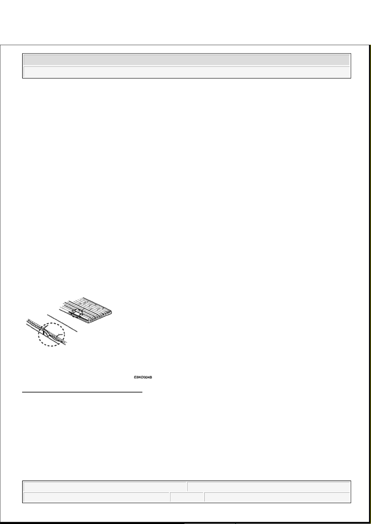
INSPECT DRIVE BELT
Visually check the belt for excessive wear, frayed cords etc.
If any defect has been found, replace the drive belt.
Fig. 2: Identifying Defective Drive Belt
Courtesy of KIA MOTORS AMERICA, INC.
VISUALLY CHECK GENERATOR WIRING AND LISTEN FOR ABNORMAL NOISES
1. Check that the wiring is in good condition.
2. Check that there is no abnormal noise from the alternator while the engine is running.
CHECK BATTERY WARNING LIGHT CIRCUIT
1. Warm up the engine and then turn it off.
NOTE: Cracks on the rib side of a belt are considered acceptable. If the belt has
chunks missing from the ribs, it should be replaced.
2008 Kia Sedona
2008 ELECTRICAL Charging System - Sedona
Microsoft
Saturday, May 22, 2010 4:06:11 PM Page 2 © 2006 Mitchell Repair Information Company, LLC.
Page 14
2. Turn off all accessories.
3. Turn the ignition switch "ON". Check that the battery warning light is lit.
4. Start the engine. Check that the light is lit.
If the light does not go off as specified, troubleshoot the discharge light circuit.
INSPECT CHARGING SYSTEM
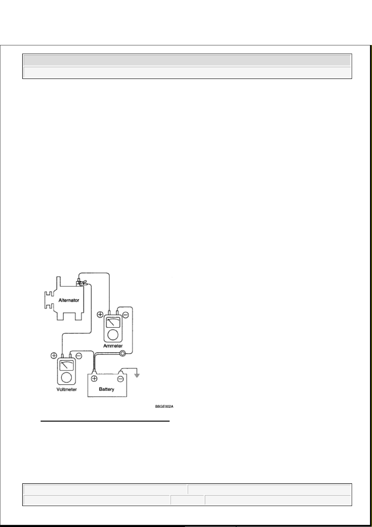
VOLTAGE DROP TEST OF GENERATOR OUTPUT WIRE
This test determines whether or not the wiring between the generator "B" terminal and the battery (+) terminal
is good by the voltage drop method.
PREPARATION
1. Turn the ignition switch to "OFF".
2. Disconnect the output wire from the generator "B" terminal. Connect the (+) lead wire of ammeter to the
"B" terminal of generator and the (-) lead wire of ammeter to the output wire. Connect the (+) lead wire o
f
voltmeter to the "B" terminal of generator and the (-) lead wire of voltmeter to the (+) terminal of battery.
Fig. 3: Charging System Circuit Diagram
Courtesy of KIA MOTORS AMERICA, INC.
TEST
1. Start the engine.
2. Turn on the headlamps and blower motor, and set the engine speed until the ammeter indicates 20A.
2008 Kia Sedona
2008 ELECTRICAL Charging System - Sedona
Microsoft
Saturday, May 22, 2010 4:06:11 PM Page 3 © 2006 Mitchell Repair Information Company, LLC.
Page 15
And then, read the voltmeter at this time.
RESULT
1. The voltmeter may indicate the standard value.
Standard value: 0.2V max
2. If the value of the voltmeter is higher than expected (above 0.2V max.), poor wiring is suspected. In this
case check the wiring from the alternator "B" terminal to the battery (+) terminal. Check for loose
connections, color change due to an overheated harness, etc. Correct them before testing again.
3. Upon completion of the test, set the engine speed at idle.
Turn off the headlamps, blower motor and the ignition switch.
OUTPUT CURRENT TEST
This test determines whether or not the generator gives an output current that is equivalent to the normal output.
PREPARATION
1. Prior to the test, check the following items and correct as necessary.
Check the battery installed in the vehicle to ensure that it is in good condition. The battery checking
method is described in BATTERY.
The battery that is used to test the output current should be one that has been partially discharged. With a
fully charged battery, the test may not be conducted correctly due to an insufficient load.
Check the tension of the generator drive belt. The belt tension check method is described in INSPECT
DRIVE BELT.
2. Turn off the ignition switch.
3. Disconnect the battery ground cable.
4. Disconnect the generator output wire from the alternator "B" terminal.
5. Connect a DC ammeter (0 to 150A) in series between the "B" terminal and the disconnected output wire.
Be sure to connect the (-) lead wire of the ammeter to the disconnected output wire.
6. Connect a voltmeter (0 to 20V) between the "B" terminal and ground. Connect the (+) lead wire to the
alternator "B" terminal and (-) lead wire to a good ground.
7. Attach an engine tachometer and connect the battery ground cable.
8. Leave the engine hood open.
NOTE: Tighten each connection securely, as a heavy current will flow. Do not rely
on clips.
2008 Kia Sedona
2008 ELECTRICAL Charging System - Sedona
Microsoft
Saturday, May 22, 2010 4:06:11 PM Page 4 © 2006 Mitchell Repair Information Company, LLC.
Page 16
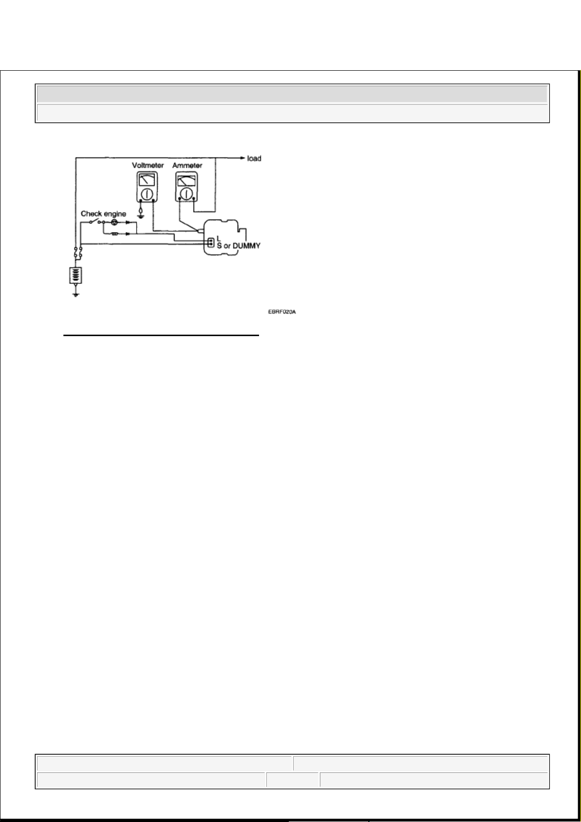
Fig. 4: Output Current Circuit Diagram
Courtesy of KIA MOTORS AMERICA, INC.
TEST
1. Check to see that the voltmeter reads as the same value as the battery voltage. If the voltmeter reads 0V,
and the open circuit in the wire between alternator "B" terminal and battery (-) terminal or poor grounding
is suspected.
2. Start the engine and turn on the headlamps.
3. Set the headlamps to high beam and the heater blower switch to HIGH, quickly increase the engine speed
to 2,500 RPM and read the maximum output current value indicated by the ammeter.
RESULT
1. The ammeter reading must be higher than the limit value. If it is lower but the generator output wire is in
good condition, remove the generator from the vehicle and test it.
Limit value: 91A min. (130A alternator)
NOTE: After the engine start up, the charging current quickly drops.
Therefore, the above operation must be done quickly to read the maximum
current value correctly.
NOTE:
The nominal output current value is shown on the nameplate affixed
to the generator body.
The output current value changes with the electrical load and the
temperature of the generator itself.
The nominal output current may not be obtained if the temperature of
the generator itself or ambient temperature is too high.
2008 Kia Sedona
2008 ELECTRICAL Charging System - Sedona
Microsoft
Saturday, May 22, 2010 4:06:11 PM Page 5 © 2006 Mitchell Repair Information Company, LLC.
Page 17
2. Upon completion of the output current test, lower the engine speed to idle and turn off the ignition switch.
3. Disconnect the battery ground cable.
4. Remove the ammeter and voltmeter and the engine tachometer.
5. Connect the generator output wire to the generator "B" terminal.
6. Connect the battery ground cable.
REGULATED VOLTAGE TEST
The purpose of this test is to check that the electronic voltage regulator controls voltage correctly.
PREPARATION
1. Prior to the test, check the following items and correct if necessary.
Check that the battery installed on the vehicle is fully charged. The battery checking method is described
in BATTERY.
Check the alternator drive belt tension. The belt tension check method is described in INSPECT DRIVE
BELT.
2. Turn ignition switch to "OFF".
3. Disconnect the battery ground cable.
4. Connect a digital voltmeter between the "B" terminal of the alternator and ground. Connect the (+) lead of
the voltmeter to the "B" terminal of the alternator. Connect the (-) lead to good ground or the battery (-)
terminal.
5. Disconnect the alternator output wire from the alternator "B" terminal.
6. Connect a DC ammeter (0 to 150A) in series between the "B" terminal and the disconnected output wire.
Connect the (-) lead wire of the ammeter to the disconnected output wire.
7. Attach the engine tachometer and connect the battery ground cable.
In such a case, reduce the temperature before testing again.
2008 Kia Sedona
2008 ELECTRICAL Charging System - Sedona
Microsoft
Saturday, May 22, 2010 4:06:11 PM Page 6 © 2006 Mitchell Repair Information Company, LLC.
Page 18
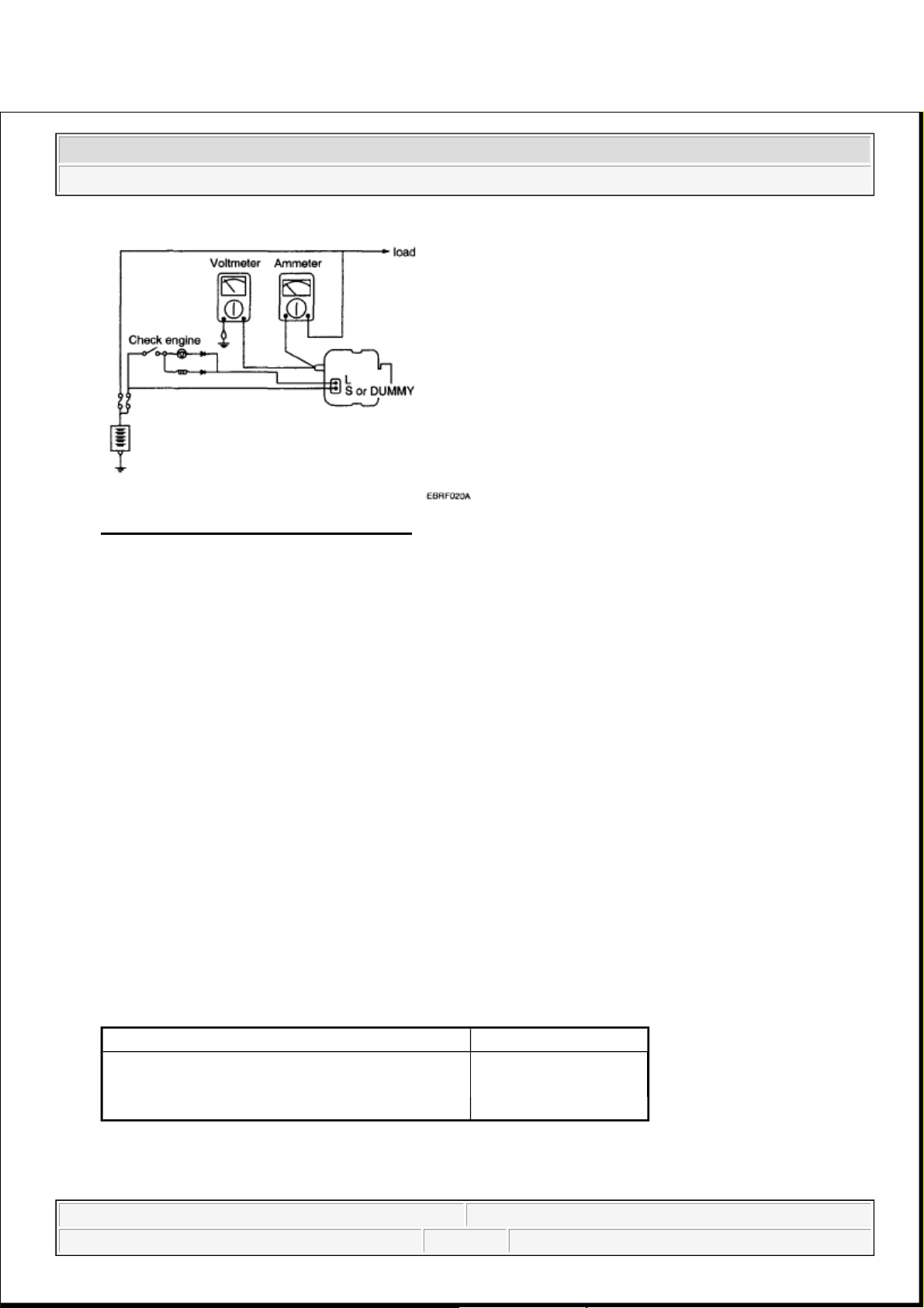
Fig. 5: Output Current Circuit Diagram
Courtesy of KIA MOTORS AMERICA, INC.
TEST
1. Turn on the ignition switch and check to see that the voltmeter indicates the following value.
Voltage: Battery voltage
If it reads 0V, there is an open circuit in the wire between the generator "B" terminal and the battery and
the battery (-) terminal.
2. Start the engine. Keep all lights and accessories off.
3. Run the engine at a speed of about 2,500 RPM and read the voltmeter when the generator output current
drops to 10A or less
RESULT
1. If the voltmeter reading agrees with the value listed in the regulating voltage table below, the voltage
regulator is functioning correctly. If the reading is other than the standard value, the voltage regulator or
the alternator is faulty.
REGULATING VOLTAGE TABLE
REGULATING VOLTAGE CHART
2. Upon completion of the test, reduce the engine speed to idle, and turn off the ignition switch.
3. Disconnect the battery ground cable.
Voltage regulator ambient temperature °C (°F)Regulating voltage (V)
-30 (-22) 14.2-15.3
25 (77) 14.2-14.8
135 (275) 13.3-14.8
2008 Kia Sedona
2008 ELECTRICAL Charging System - Sedona
Microsoft
Saturday, May 22, 2010 4:06:11 PM Page 7 © 2006 Mitchell Repair Information Company, LLC.
Page 19
4. Remove the voltmeter and ammeter and the engine tachometer.
5. Connect the generator output wire to the generator "B" terminal.
6. Connect the battery ground cable.
ALTERNATOR
REMOVAL
1. Disconnect the battery negative terminal first, then the positive terminal.
2. Disconnect the alternator connector, and remove the cable from alternator "B" terminal.
3. Remove the drive belt.
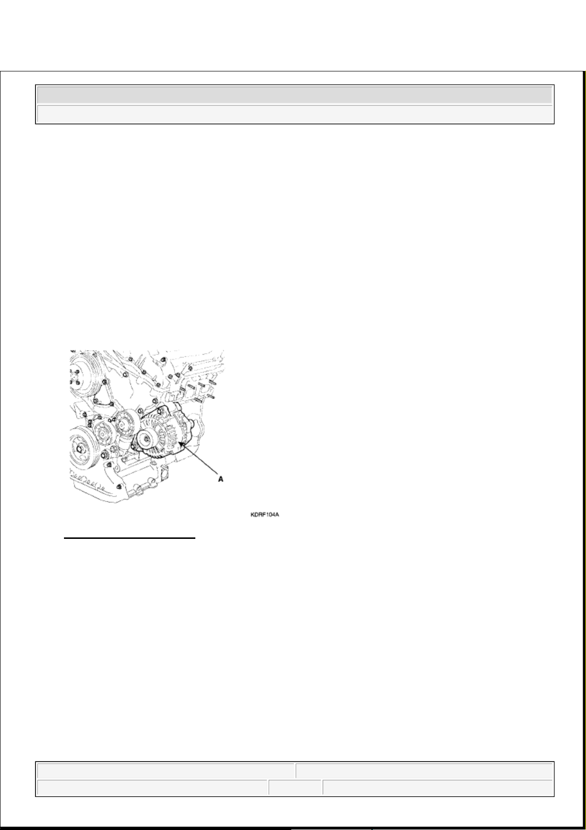
4. Pull out the through bolts and then remove the alternator (A).
Fig. 6: Locating Generator
Courtesy of KIA MOTORS AMERICA, INC.
5. Installation is the reverse of removal.
COMPONENT
2008 Kia Sedona
2008 ELECTRICAL Charging System - Sedona
Microsoft
Saturday, May 22, 2010 4:06:11 PM Page 8 © 2006 Mitchell Repair Information Company, LLC.
Page 20

Fig. 7: Exploded View Of Generator
Courtesy of KIA MOTORS AMERICA, INC.
DISASSEMBLY
1. Remove the
g
enerator cover (A) using a screwdriver (B).
2008 Kia Sedona
2008 ELECTRICAL Charging System - Sedona
Microsoft
Saturday, May 22, 2010 4:06:11 PM Page 9 © 2006 Mitchell Repair Information Company, LLC.
Page 21
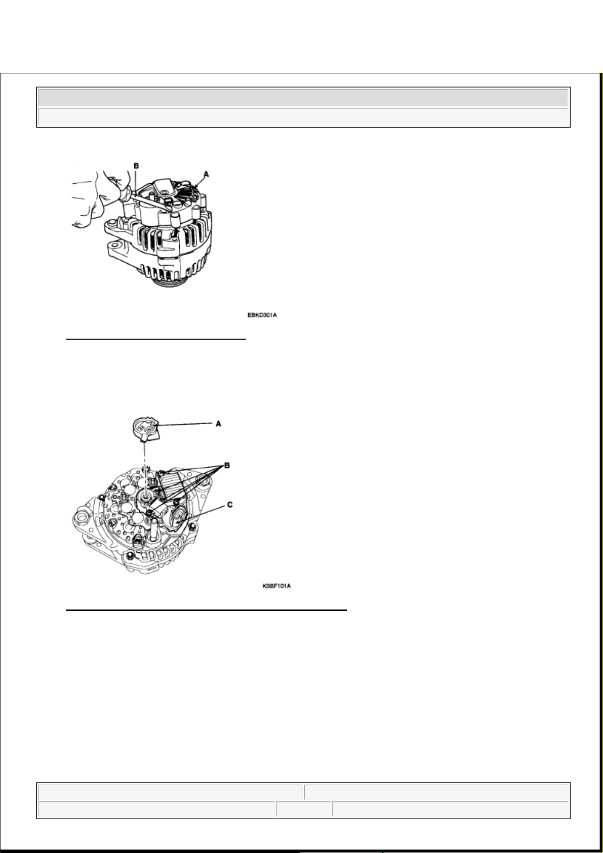
Fig. 8: Identifying Generator Cover
Courtesy of KIA MOTORS AMERICA, INC.
2. Remove the slip ring guide (A).
3. Loosen the mounting bolts (B) and disconnect the brush holder assembly (C).
Fig. 9: Identifying Slip Ring Guide And Mounting Bolts
Courtesy of KIA MOTORS AMERICA, INC.
4. Remove the rectifier (A) with 4 screw.
2008 Kia Sedona
2008 ELECTRICAL Charging System - Sedona
Microsoft
Saturday, May 22, 2010 4:06:11 PM Page 10 © 2006 Mitchell Repair Information Company, LLC.
Page 22
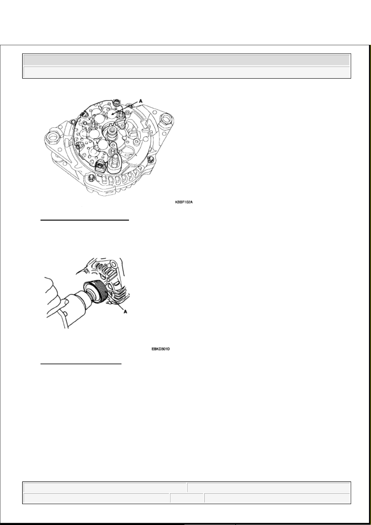
Fig. 10: Identifying Rectifier
Courtesy of KIA MOTORS AMERICA, INC.
5. Remove the nut, pulley (A) and spacer.
Fig. 11: Identifying Pulley
Courtesy of KIA MOTORS AMERICA, INC.
6. Loosen the 4 nuts (A).
2008 Kia Sedona
2008 ELECTRICAL Charging System - Sedona
Microsoft
Saturday, May 22, 2010 4:06:11 PM Page 11 © 2006 Mitchell Repair Information Company, LLC.
Page 23
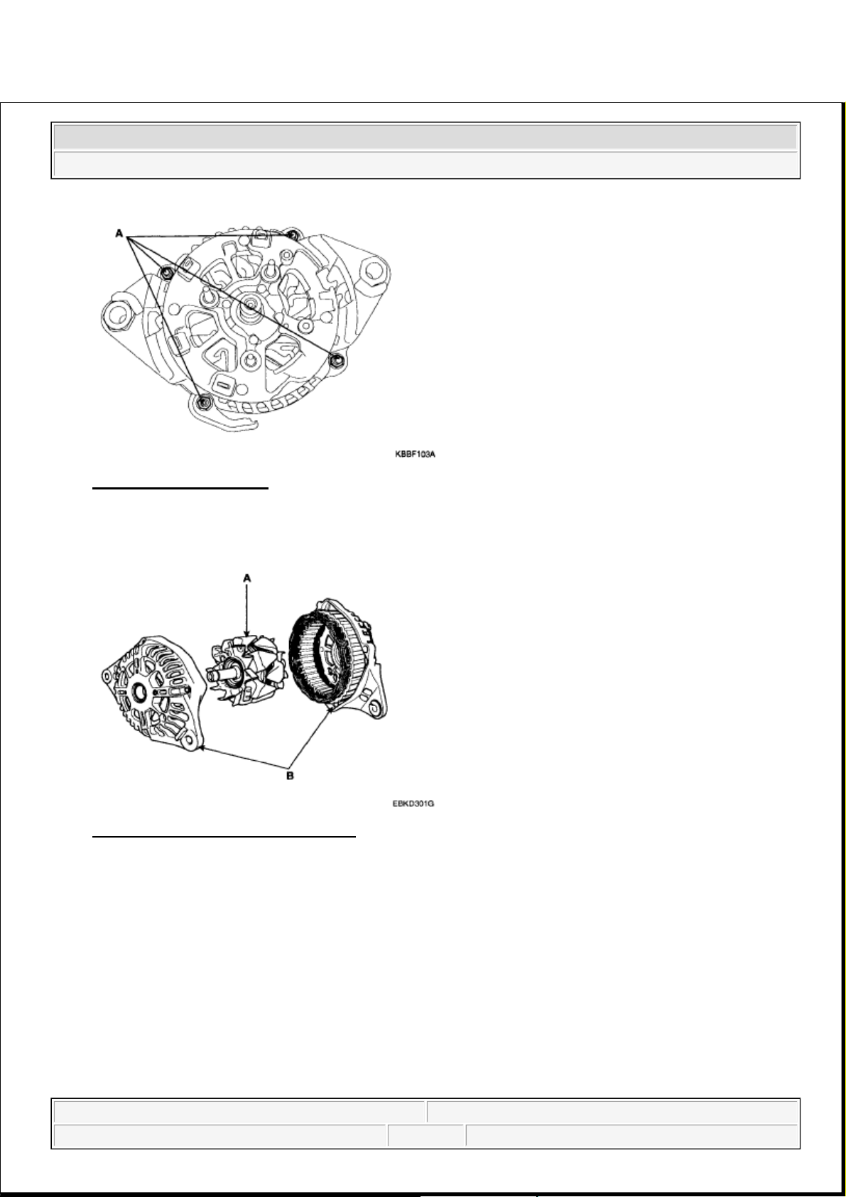
Fig. 12: Identifying Bolts
Courtesy of KIA MOTORS AMERICA, INC.
7. Disconnect the rotor (A) and cover (B).
Fig. 13: Identifying Rotor And Cover
Courtesy of KIA MOTORS AMERICA, INC.
8. Reassembly is the reverse order of disassembly.
INSPECTION
INSPECT ROTOR
1. Check that there is continuity between the slip rings (A).
2008 Kia Sedona
2008 ELECTRICAL Charging System - Sedona
Microsoft
Saturday, May 22, 2010 4:06:11 PM Page 12 © 2006 Mitchell Repair Information Company, LLC.
Page 24
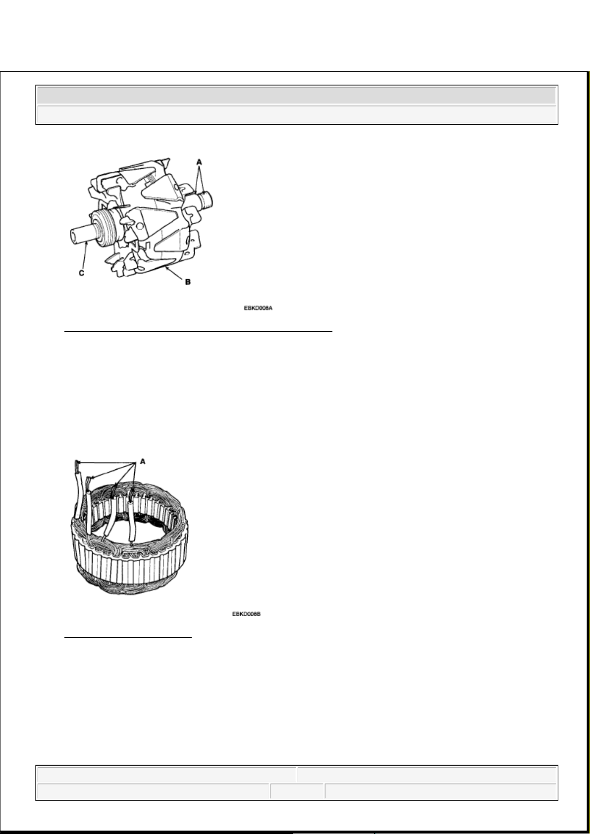
Fig. 14: Identifying Slip Rings, Rotor And Rotor Shaft
Courtesy of KIA MOTORS AMERICA, INC.
2. Check that there is no continuity between the slip rings and the rotor (B) or rotor shaft (C).
3. If the rotor fails either continuity check, replace the generator.
INSPECT STATOR
1. Check that there is continuity between each pair of leads (A).
Fig. 15: Identifying Leads
Courtesy of KIA MOTORS AMERICA, INC.
2. Check that there is no continuity between each lead and the coil core.
3. If the coil fails either continuity check, replace the alternator.
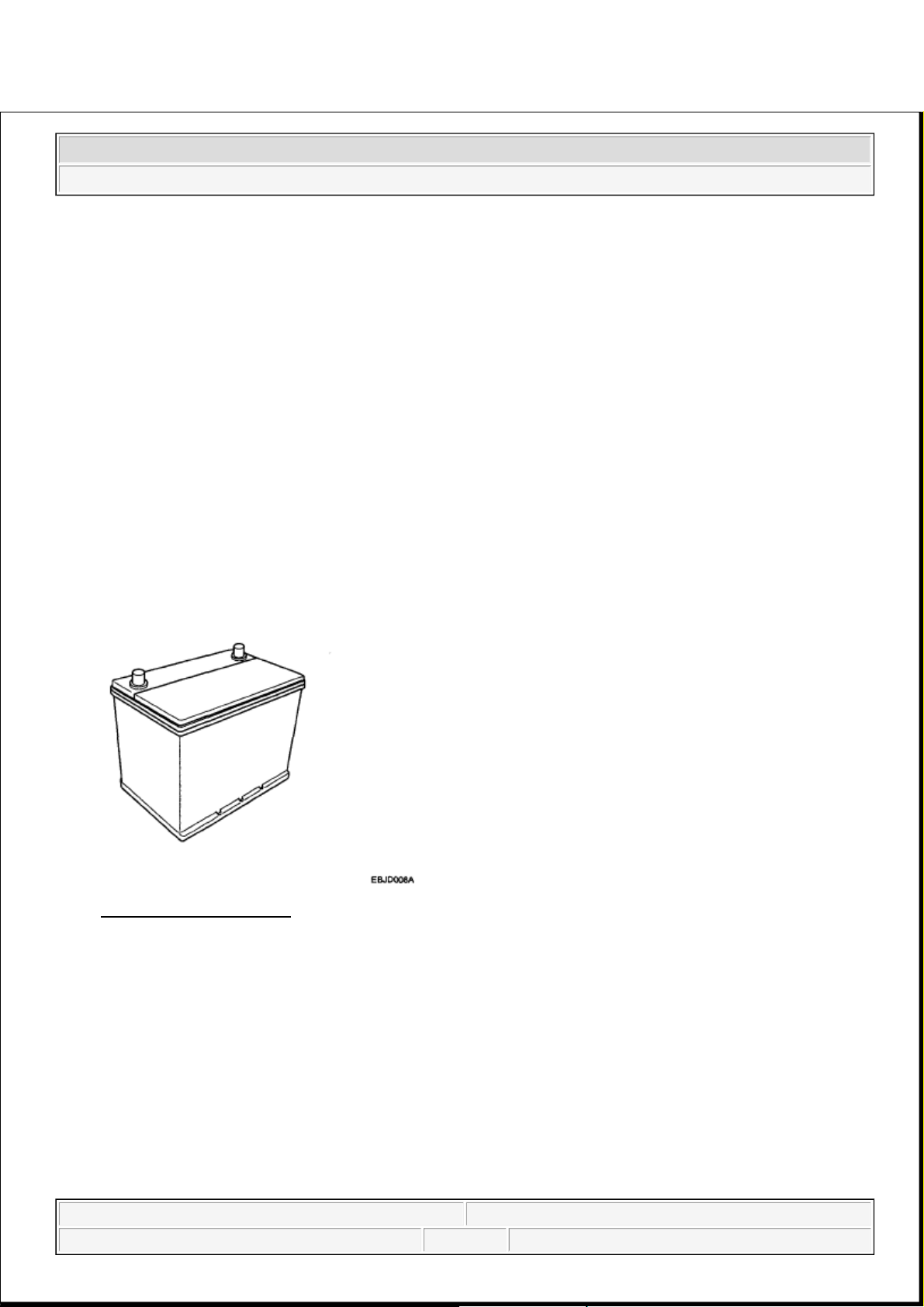
BATTERY
DESCRIPTION
2008 Kia Sedona
2008 ELECTRICAL Charging System - Sedona
Microsoft
Saturday, May 22, 2010 4:06:11 PM Page 13 © 2006 Mitchell Repair Information Company, LLC.
Page 25
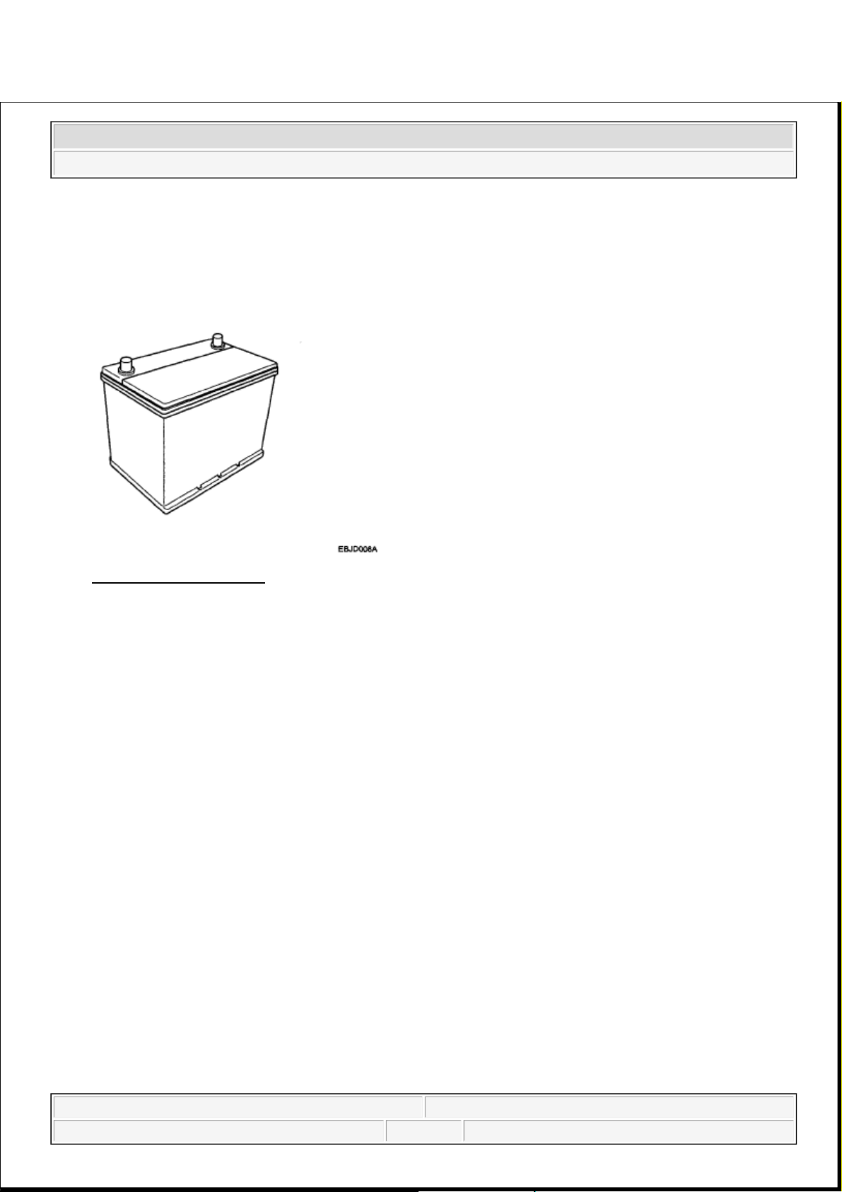
1. The maintenance-free battery is, as the name implies, totally maintenance free and has no removable
battery cell caps.
2. Water never needs to be added to the maintenance-free battery.
3. The battery is completely sealed, except for small vent holes in the cover.
Fig. 16: View Of Battery
Courtesy of KIA MOTORS AMERICA, INC.
INSPECTION
BATTERY DIAGNOSTIC TEST (1)
CHECKING FLOW
2008 Kia Sedona
2008 ELECTRICAL Charging System - Sedona
Microsoft
Saturday, May 22, 2010 4:06:11 PM Page 14 © 2006 Mitchell Repair Information Company, LLC.
Page 26
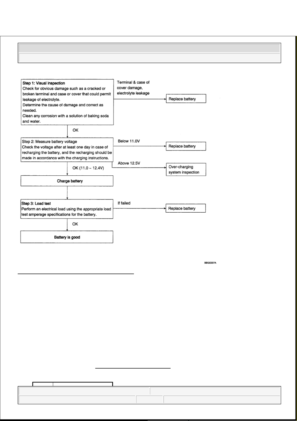
Fig. 17: Battery Diagnostic Test Flow Diagram
Courtesy of KIA MOTORS AMERICA, INC.
LOAD TEST
1. Perform the following steps to complete the load test procedure for maintenance free batteries.
2. Connect the load tester clamps to the terminals and proceed with the test as follow:
1. If the battery has been on charge, remove the surface charge by connecting a 300 ampere load for
15 seconds.
2. Connect the voltmeter and apply the specified load.
3. Read the voltage after the load has been applied for 15 seconds.
4. Disconnect the load.
5. Compare the voltage reading with the minimum and replace the battery if battery test voltage is
below that shown in BATTERY TEST VOLTAGE
.
BATTERY TEST VOLTAGE
2008 Kia Sedona
2008 ELECTRICAL Charging System - Sedona
Microsoft
Saturday, May 22, 2010 4:06:11 PM Page 15 © 2006 Mitchell Repair Information Company, LLC.
Page 27
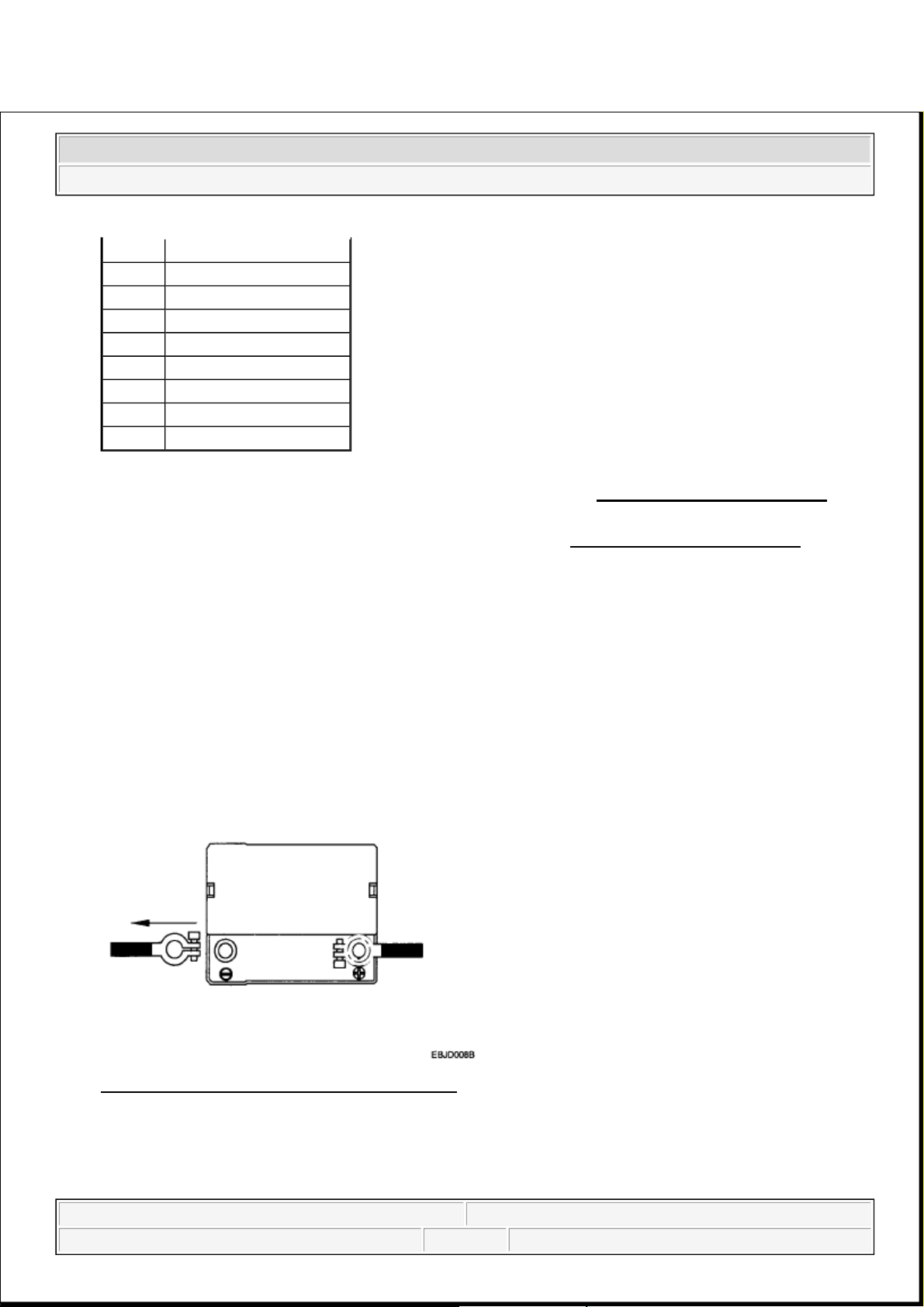
BATTERY DIAGNOSTIC TEST (2)
1. Make sure the ignition switch and all accessories are in the OFF position.
2. Disconnect the battery cables (negative first).
3. Remove the battery from the vehicle.
Fig. 18: Disconnecting Negative Battery Cable
Courtesy of KIA MOTORS AMERICA, INC.
4. Inspect the battery tray for damage caused by the loss of electrolyte. If acid damage is present, it will be
necessary to clean the area with a solution of clean warm water and baking soda. Scrub the area with a
stiff brush and wipe off with a cloth moistened with baking soda and water.
Voltage Temperature
9.6V 20°C (68.0°F) and above
9.5V 16°C (60.8°F)
9.4V 10°C (50.0°F)
9.3V 4°C (39.2°F)
9.1V -1°C (30.2°F)
8.9V -7°C (19.4°F)
8.7V -12°C (10.4°F)
8.5V -18°C (-0.4°F)
NOTE:
If the voltage is greater than shown in BATTERY TEST VOLTAGE, the
battery is good.
If the voltage is less than shown in BATTERY TEST VOLTAGE,
replace the battery.
CAUTION: Care should be taken in the event the battery case is cracked or
leaking, to protect your skin from the electrolyte.
Heavy rubber gloves (not the household type) should be wore when
removing the battery.
2008 Kia Sedona
2008 ELECTRICAL Charging System - Sedona
Microsoft
Saturday, May 22, 2010 4:06:11 PM Page 16 © 2006 Mitchell Repair Information Company, LLC.
Page 28
5. Clean the top of the battery with the same solution as described above.
6. Inspect the battery case and cover for cracks. If cracks are present, the battery must be replaced.
7. Clean the battery posts with a suitable battery post tool.
8. Clean the inside surface of the terminal clamps with a suitable battery cleaning tool. Replace damaged or
frayed cables and broken terminal clamps.
9. Install the battery in the vehicle.
10. Connect the cable terminals to the battery post, making sure tops of the terminals are flush with the tops
of the posts.
11. Tighten the terminal nuts securely.
12. Coat all connections with light mineral grease after tightening.
Fig. 19: View Of Battery
Courtesy of KIA MOTORS AMERICA, INC.
CAUTION: When batteries are being charged, an explosive gas forms beneath
the cover of each cell. Do not smoke near batteries being charged or
which have recently been charged. Do not break live circuit at the
terminals of batteries being charged. A spark will occur when the
circuit is broken. Keep open flames away from battery.
2008 Kia Sedona
2008 ELECTRICAL Charging System - Sedona
Microsoft
Saturday, May 22, 2010 4:06:11 PM Page 17 © 2006 Mitchell Repair Information Company, LLC.
Page 29
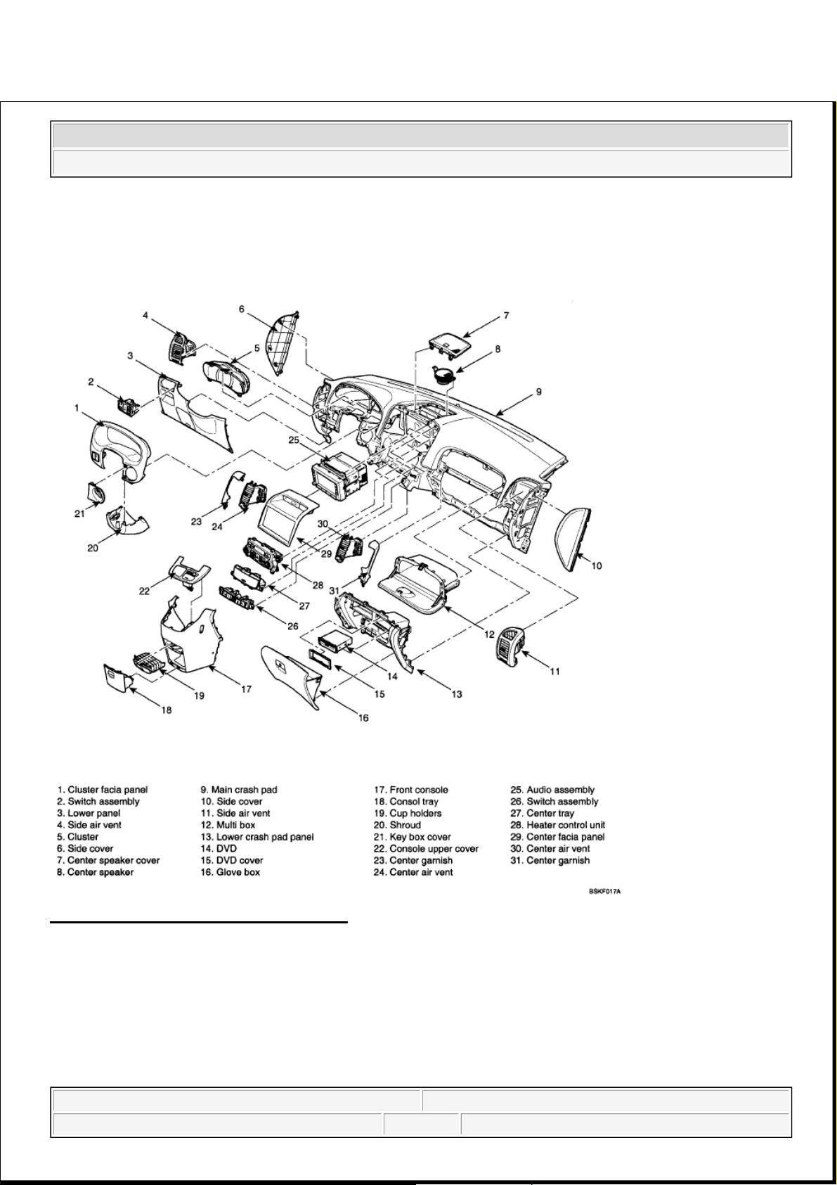
CRASH PAD
COMPONENTS
Fig. 7: Identifying Crash Pad Components
Courtesy of KIA MOTORS AMERICA, INC.
REPLACEMENT
CLUSTER FASCIA PANEL REPLACEMENT
NOTE:
When prying with a flat-tipped screwdriver, wrap it with protective tape,
and apply protective tape around the related parts, to prevent damage.
2008 Kia Sedona
2008 ACCESSORIES & BODY, CAB Interior - Sedona
2008 Kia Sedona
2008 ACCESSORIES & BODY, CAB Interior - Sedona
Microsoft
Saturday, May 22, 2010 6:56:12 PM Page 1 © 2006 Mitchell Repair Information Company, LLC.
Microsoft
Saturday, May 22, 2010 6:56:15 PM Page 1 © 2006 Mitchell Repair Information Company, LLC.
Page 30
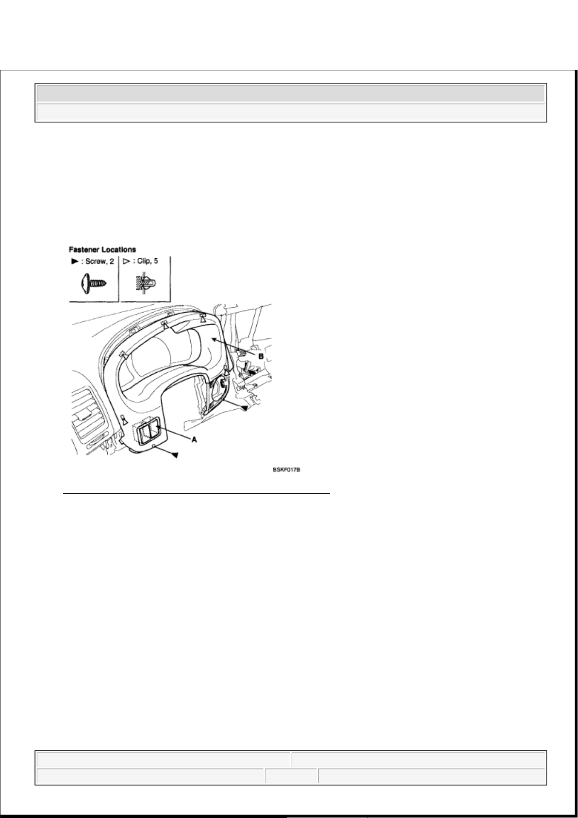
1. Tilt the steering column down.
2. Remove the screws, and detach the clips.
3. After disconnecting the connector (A), remove the cluster fascia panel (B).
Fig. 8: Identifying Connector And Cluster Fascia Panel
Courtesy of KIA MOTORS AMERICA, INC.
4. Installation is the reverse of removal.
CENTER FASCIA PANEL REPLACEMENT
1. Detach the clips, then remove the center fascia panel (A).
Put on gloves to protect your hands.
NOTE:
Make sure the connector is plugged in properly.
NOTE:
When prying with a flat-tipped screwdriver, wrap it with protective tape,
and apply protective tape around the related parts, to prevent damage.
Put on gloves to protect your hands.
2008 Kia Sedona
2008 ACCESSORIES & BODY, CAB Interior - Sedona
Microsoft
Saturday, May 22, 2010 6:56:12 PM Page 2 © 2006 Mitchell Repair Information Company, LLC.
Page 31

Fig. 9: Identifying Center Fascia Panel And Clip
Courtesy of KIA MOTORS AMERICA, INC.
2. Installation is the reverse the removal.
LOWER PANEL REPLACEMENT
1. Remove the crash pad side cover. See COVER REPLACEMENT.
2. Remove the fuse box cover (A).
Fig. 10: Identifying Fuse Box Cover
Courtesy of KIA MOTORS AMERICA, INC.
3. After loosenin
g
the crash pad lower panel mounting screws, then remove the lower panel (B).
NOTE:
Make sure the connector is plugged in properly.
2008 Kia Sedona
2008 ACCESSORIES & BODY, CAB Interior - Sedona
Microsoft
Saturday, May 22, 2010 6:56:12 PM Page 3 © 2006 Mitchell Repair Information Company, LLC.
Page 32

4. Remove the parking brake lever (C).
Fig. 11: Identifying Lower Panel, Parking Brake Lever And Fastener Locations
Courtesy of KIA MOTORS AMERICA, INC.
5. Disconnect the connector (A).
Fig. 12: Identifying Connector
Courtesy of KIA MOTORS AMERICA, INC.
6. Installation is the reverse of removal.
HEATER CONTROL UNIT REPLACEMENT
2008 Kia Sedona
2008 ACCESSORIES & BODY, CAB Interior - Sedona
Microsoft
Saturday, May 22, 2010 6:56:12 PM Page 4 © 2006 Mitchell Repair Information Company, LLC.
Page 33

1. Remove the center fascia panel. See REPLACEMENT.
2. Remove the console upper cover (A).
3. Disconnect the connector (B).
Fig. 13: Identifying Center Cover And Connector
Courtesy of KIA MOTORS AMERICA, INC.
4. Loosen the air vent mounting screw, then remove the air vent (A).
2008 Kia Sedona
2008 ACCESSORIES & BODY, CAB Interior - Sedona
Microsoft
Saturday, May 22, 2010 6:56:12 PM Page 5 © 2006 Mitchell Repair Information Company, LLC.
Page 34

Fig. 14: Identifying Air Vent And Fastener Locations
Courtesy of KIA MOTORS AMERICA, INC.
5. After loosening the heater control unit mounting screws, then remove the heater control unit (A).
Fig. 15: Identifying Heater Control Unit And Screw
Courtesy of KIA MOTORS AMERICA, INC.
6. Installation is the reverse of removal.
Fig. 16: Identifying Connector (1 Of 2)
Courtesy of KIA MOTORS AMERICA, INC.
NOTE:
Make sure the connector (A) is plugged in properly.
2008 Kia Sedona
2008 ACCESSORIES & BODY, CAB Interior - Sedona
Microsoft
Saturday, May 22, 2010 6:56:12 PM Page 6 © 2006 Mitchell Repair Information Company, LLC.
Page 35

Fig. 17: Identifying Connector (2 Of 2)
Courtesy of KIA MOTORS AMERICA, INC.
CLUSTER REPLACEMENT
1. Remove the cluster fascia panel. See REPLACEMENT.
2. Loosen the screws.
Fig. 18: Identifying Cluster Panel And Screw
Courtesy of KIA MOTORS AMERICA, INC.
3. Disconnect the cluster connectors (A), then remove the cluster (B).
2008 Kia Sedona
2008 ACCESSORIES & BODY, CAB Interior - Sedona
Microsoft
Saturday, May 22, 2010 6:56:12 PM Page 7 © 2006 Mitchell Repair Information Company, LLC.
Page 36

Fig. 19: Identifying Cluster Connectors And Cluster
Courtesy of KIA MOTORS AMERICA, INC.
4. Installation is the reverse of removal.
AUDIO ASSEMBLY REPLACEMENT
1. Remove the center fascia panel. See REPLACEMENT.
2. Loosen the screws.
Fig. 20: Identifying Center Fascia Panel And Screw
Courtesy of KIA MOTORS AMERICA, INC.
NOTE:
Make sure the connector are plugged in properly.
2008 Kia Sedona
2008 ACCESSORIES & BODY, CAB Interior - Sedona
Microsoft
Saturday, May 22, 2010 6:56:12 PM Page 8 © 2006 Mitchell Repair Information Company, LLC.
Page 37

3. Disconnect the connector (A), then remove the audio assembly (B).
Fig. 21: Identifying Connector And Audio Assembly
Courtesy of KIA MOTORS AMERICA, INC.
4. Installation is the reverse of removal.
AIR VENT REPLACEMENT
1. Remove the side cover. See COVER REPLACEMENT.
2. Loosen the mounting screws, then remove the air vent (A).
NOTE:
Make sure the connector are plugged in properly.
NOTE:
When prying with a flat-tipped screwdriver, wrap it with protective tape,
and apply protective tape around the related parts, to prevent damage.
Put on gloves to protect your hands.
2008 Kia Sedona
2008 ACCESSORIES & BODY, CAB Interior - Sedona
Microsoft
Saturday, May 22, 2010 6:56:12 PM Page 9 © 2006 Mitchell Repair Information Company, LLC.
Page 38

Fig. 22: Identifying Air Vent
Courtesy of KIA MOTORS AMERICA, INC.
3. Installation is the reverse of removal.
GLOVE BOX REPLACEMENT
1. Disconnect the damper (B) from the glove box (A).
2008 Kia Sedona
2008 ACCESSORIES & BODY, CAB Interior - Sedona
Microsoft
Saturday, May 22, 2010 6:56:12 PM Page 10 © 2006 Mitchell Repair Information Company, LLC.
Page 39

Fig. 23: Identifying Damper And Glove Box
Courtesy of KIA MOTORS AMERICA, INC.
2. Remove the glove box (A) from the lift (B).
Fig. 24: Identifying Glove Box And Lift
Courtesy of KIA MOTORS AMERICA, INC.
3. Disconnect the pine (A), then remove the glove box (B).
2008 Kia Sedona
2008 ACCESSORIES & BODY, CAB Interior - Sedona
Microsoft
Saturday, May 22, 2010 6:56:13 PM Page 11 © 2006 Mitchell Repair Information Company, LLC.
Page 40

Fig. 25: Identifying Pine And Glove Box
Courtesy of KIA MOTORS AMERICA, INC.
4. Installation is the reverse of removal.
COVER REPLACEMENT
1. Remove the crash pad side cover (A), crash pad center under cover (B).
1. Crash pad side cover.
NOTE:
When prying with a flat-tipped screwdriver, wrap it with protective tape,
and apply protective tape around the related parts, to prevent damage.
Put on gloves to protect your hands.
2008 Kia Sedona
2008 ACCESSORIES & BODY, CAB Interior - Sedona
Microsoft
Saturday, May 22, 2010 6:56:13 PM Page 12 © 2006 Mitchell Repair Information Company, LLC.
Page 41

Fig. 26: Identifying Crash Pad Side Cover And Clip
Courtesy of KIA MOTORS AMERICA, INC.
2. Front crash pad center under cover, LH.
Fig. 27: Identifying Center Under Cover And Clip
Courtesy of KIA MOTORS AMERICA, INC.
3. Front crash pad center under cover, RH.
2008 Kia Sedona
2008 ACCESSORIES & BODY, CAB Interior - Sedona
Microsoft
Saturday, May 22, 2010 6:56:13 PM Page 13 © 2006 Mitchell Repair Information Company, LLC.
Page 42

Fig. 28: Identifying Front Crash Pad Center Under Cover And Clip
Courtesy of KIA MOTORS AMERICA, INC.
2. Installation is the reverse of removal.
SHROUD REPLACEMENT
1. Loosen the screws.
2. Disconnect the connector, then remove the shroud assembly (A).
Fig. 29: Identifying Shroud Assembly And Screw
Courtesy of KIA MOTORS AMERICA, INC.
2008 Kia Sedona
2008 ACCESSORIES & BODY, CAB Interior - Sedona
Microsoft
Saturday, May 22, 2010 6:56:13 PM Page 14 © 2006 Mitchell Repair Information Company, LLC.
Page 43

3. Installation is the reverse of removal.
LOWER CRASH PAD PANEL REPLACEMENT
1. Remove the glove box. See GLOVE BOX REPLACEMENT.
2. Remove the side air vent. See AUDIO ASSEMBLY REPLACEMENT.
3. Remove the DVD cover (A).
Fig. 30: Identifying DVD Cover
Courtesy of KIA MOTORS AMERICA, INC.
4. Loosen the mounting screws, remove the DVD (A).
Fig. 31: Identifying DVD And Screw
2008 Kia Sedona
2008 ACCESSORIES & BODY, CAB Interior - Sedona
Microsoft
Saturday, May 22, 2010 6:56:13 PM Page 15 © 2006 Mitchell Repair Information Company, LLC.
Page 44

Courtesy of KIA MOTORS AMERICA, INC.
5. Disconnect the connector (A).
Fig. 32: Identifying Connector
Courtesy of KIA MOTORS AMERICA, INC.
6. After loosening the upper glove box mounting screws, then remove the upper glove box (A).
Fig. 33: Identifying Upper Glove Box And Fastener Locations
Courtesy of KIA MOTORS AMERICA, INC.
7. Loosen the panel mounting bolts and screws.
8. After disconnecting the connector, remove the panel (A).
2008 Kia Sedona
2008 ACCESSORIES & BODY, CAB Interior - Sedona
Microsoft
Saturday, May 22, 2010 6:56:13 PM Page 16 © 2006 Mitchell Repair Information Company, LLC.
Page 45

Fig. 34: Identifying Panel And Fastener Locations
Courtesy of KIA MOTORS AMERICA, INC.
9. Installation is the reverse of removal.
CRASH PAD REPLACEMENT
1. Remove the following items.
Front seat. See FRONT SEAT .
Cluster fascia panel, cluster. See CLUSTER REPLACEMENT.
Audio assembly. See AUDIO ASSEMBLY REPLACEMENT.
Glove box. See GLOVE BOX REPLACEMENT.
Side cover, center under cover. See COVER REPLACEMENT.
Front pillar trim. See FRONT PILLAR TRIM.
2. Remove the photo sensor (C), speaker connector (B).
3. Disconnect the passenger's air bag connector (A). Loosen the bolt and nut, then remove the crash pad (D).
4. Installation is the reverse of removal.
NOTE:
When prying with a flat-tipped screwdriver, wrap it with protective tape,
and apply protective tape around the related parts, to prevent damage.
Put on gloves to protect your hands.
NOTE:
Make sure the crash pad fits onto the guide pins correctly.
Before tightening the bolts, make sure the crash pad wire harnesses
2008 Kia Sedona
2008 ACCESSORIES & BODY, CAB Interior - Sedona
Microsoft
Saturday, May 22, 2010 6:56:13 PM Page 17 © 2006 Mitchell Repair Information Company, LLC.
Page 46

Fig. 35: Identifying Crash Pad Fastener Locations
Courtesy of KIA MOTORS AMERICA, INC.
COWL CROSSBAR ASSEMBLY REPLACEMENT
1. Remove the crash pad. See CRASH PAD REPLACEMENT.
2. Remove the connectors.
are not pinched.
Make sure the connectors are plugged in properly, and the antenna
lead is connected properly.
Enter the anti-theft code for the radio, then enter.
NOTE:
When prying with a flat-tipped screwdriver, wrap it with protective tape,
and apply protective tape around the related parts, to prevent damage.
Put on gloves to protect your hands.
2008 Kia Sedona
2008 ACCESSORIES & BODY, CAB Interior - Sedona
Microsoft
Saturday, May 22, 2010 6:56:13 PM Page 18 © 2006 Mitchell Repair Information Company, LLC.
Page 47

3. Loosen the bolts and nuts, then remove cowl crossbar assembly (A).
4. Installation is the reverse of removal.
Fig. 36: Identifying Cowl Crossbar Fastener Locations
Courtesy of KIA MOTORS AMERICA, INC.
NOTE:
Make sure the crash pad fits onto the guide pins correctly.
Before tightening the bolts, make sure the crash pad wire harnesses
are not pinched.
Make sure the connectors are plugged in properly, and the antenna
lead is connected properly.
Enter the anti-theft code for the radio, then enter the customer's radio
station presets.
2008 Kia Sedona
2008 ACCESSORIES & BODY, CAB Interior - Sedona
Microsoft
Saturday, May 22, 2010 6:56:13 PM Page 19 © 2006 Mitchell Repair Information Company, LLC.
Page 48

2008 ACCESSORIES & BODY, CAB
Horns - Sedona
COMPONENT LOCATION
Fig. 1: Horn System Component Locations
Courtesy of KIA MOTORS AMERICA, INC.
HORN
REPLACEMENT
1. Remove the bolt from the high pitch horn and the low pitch horn and disconnect the horn connector, then
remove the horn.
2. Installation is the reverse of removal.
2008 Kia Sedona EX
2008 ACCESSORIES & BODY, CAB Horns - Sedona
2008 Kia Sedona EX
2008 ACCESSORIES & BODY, CAB Horns - Sedona
Microsoft
Monday, May 24, 2010 4:12:43 PM Page 1 © 2006 Mitchell Repair Information Company, LLC.
Microsoft
Monday, May 24, 2010 4:12:46 PM Page 1 © 2006 Mitchell Repair Information Company, LLC.
Page 49

Fig. 2: Identifying Horn
Courtesy of KIA MOTORS AMERICA, INC.
ADJUSTMENT
Operate the horn, and adjust the tone to a suitable level by turning the adjusting screw.
Fig. 3: Adjusting Horn
Courtesy of KIA MOTORS AMERICA, INC.
INSPECTION
Test the horn by connecting battery voltage to the terminal 1, and ground terminal 2.
The horn should make a sound. If the horn fails to make a sound, replace it.
NOTE: After adjustment, apply a small amount of paint around the screw head to keep
it from loosening.
2008 Kia Sedona EX
2008 ACCESSORIES & BODY, CAB Horns - Sedona
Microsoft
Monday, May 24, 2010 4:12:43 PM Page 2 © 2006 Mitchell Repair Information Company, LLC.
Page 50

2008 HVAC
HVAC General - Sedona
SPECIFICATION
AIR CONDITIONER
AIR CONDITIONER SPECIFICATION
BLOWER UNIT
BLOWER UNIT CHART
HEATER AND EVAPORATOR UNIT
HEATER AND EVAPORATOR UNIT CHART
Item
Specification
3.8L
Compressor
Type Fixed type (Swash plate)
Oil type & Capacity FD46XG (PAG), 210 ± 10cc
Pulley type 6PK-TYPE
Displacement 214cc/rev
Condenser Heat rejection 19,500 ± 5% kcal/hr
APT (A/C pressure transducer) The method to measure the
pressure
Vout = 0.00878835* pa +
0.37081095
Expansion valve Type Block (L-TYPE)
Refrigerant
Type R-134a
Capacity [oz. (g)] 31.7 ± 0.88 (900 ± 25)
Item Specification
Fresh and recirculation Operating method Actuator
Blower
Type Sirocco
Speed step Auto + 8 speed (Automatic)
1-8 speed (Manual)
Speed control Power Mosfet
Air filter Type Particle filter
Item Specification
Heater
Type Pin & Tube type
Heating capacity 4,700 ± 5% kcal/hr
Mode operating method Actuator
Temperature operating method Actuator
Evaporator
Temperature control type Evaporator temperature sensor
2008 Kia Sedona EX
2008 HVAC HVAC General - Sedona
2008 Kia Sedona EX
2008 HVAC HVAC General - Sedona
Microsoft
Monday, May 24, 2010 4:02:38 PM Page 1 © 2006 Mitchell Repair Information Company, LLC.
Microsoft
Monday, May 24, 2010 4:02:41 PM Page 1 © 2006 Mitchell Repair Information Company, LLC.
Page 51

TROUBLESHOOTING
PROBLEM SYMPTOMS TABLE
Before replacing or repairing air conditioning components, first determine if the malfunction is due to the
refrigerant charge, air flow or compressor.
Use the Troubleshooting table to help you find the cause of the problem. See TROUBLESHOOTING
CHART. The numbers indicate the priority of the likely cause of the problem. Check each part in order. If
necessary, replace these parts.
After correcting the malfunction, check the complete system to ensure that performance is satisfactory.
STANDARD:
TROUBLESHOOTING CHART
A/C ON/OFF °C (°F)]
ON: 2.6 ± 0.5 (36.7 ± 0.9)
OFF: 1.1 ± 0.5 (34.0 ± 0.9)
Symptom Suspect Area
No blower operation
1. Blower fuse
2. Blower relay
3. Blower motor
4. Power Mosfet
5. Blower speed control switch
6. Wire harness
No air temperature control
1. Engine coolant capacity
2. Heater control assembly
No compressor operation
1. Refrigerant capacity
2. A/C Fuse
3. Magnetic clutch
4. Compressor
5. A/C pressure transducer
6. A/C switch
7. Evaporator temperature sensor
8. Wire harness
No cool air comes out
1. Refrigerant capacity
2. Refrigerant pressure
3. Drive belt
4. Magnetic clutch
5. Compressor
6. A/C pressure transducer
7. Evaporator temperature sensor
8. A/C switch
2008 Kia Sedona EX
2008 HVAC HVAC General - Sedona
Microsoft
Monday, May 24, 2010 4:02:38 PM Page 2 © 2006 Mitchell Repair Information Company, LLC.
Page 52

SPECIAL TOOLS
SPECIAL TOOLS CHART
9. Heater control assembly
10. Wire harness
Insufficient cooling
1.Refrigerant capacity
2. Drive belt
3. Magnetic clutch
4. Compressor
5. Condenser
6. Expansion valve
7. Evaporator
8. Refrigerant lines
9. A/C pressure transducer
10. Heater control assembly
No engine idle-up when A/C switch ON
1. Engine ECM
2. Wire harness
No air inlet control 1. Heater control assembly
No mode control
1. Heater control assembly
2. Mode actuator
No cooling fan operation
1. Cooling fan fuse
2. Fan motor
3. Engine ECM
4. Wire harness
Tool (Number and name) Illustration Use
09977-29000
Disc & hub assembly bolt remover
Removal and installation of the
disc & hub assembly bolt
2008 Kia Sedona EX
2008 HVAC HVAC General - Sedona
Microsoft
Monday, May 24, 2010 4:02:38 PM Page 3 © 2006 Mitchell Repair Information Company, LLC.
Page 53

2008 ACCESSORIES & BODY, CAB
Power Door Mirrors - Sedona
COMPONENT LOCATION
Fig. 1: Power Door Mirror Component Locations
Courtesy of KIA MOTORS AMERICA, INC.
POWER DOOR MIRROR ACTUATOR
INSPECTION
1. Remove the front door quadrant inner cover (A). Take care not to damage fixing clips. Refer to FRONT
DOOR .
2008 Kia Sedona EX
2008 ACCESSORIES & BODY, CAB Power Door Mirrors - Sedona
2008 Kia Sedona EX
2008 ACCESSORIES & BODY, CAB Power Door Mirrors - Sedona
Microsoft
Monday, May 24, 2010 4:12:07 PM Page 1 © 2006 Mitchell Repair Information Company, LLC.
Microsoft
Monday, May 24, 2010 4:12:11 PM Page 1 © 2006 Mitchell Repair Information Company, LLC.
Page 54

Fig. 2: Identifying Front Door Quadrant Inner Cover
Courtesy of KIA MOTORS AMERICA, INC.
2. Disconnect the power door mirror connector from the harness.
3. Verify that the mirror operates properly. See Fig. 4.
Fig. 3: Identifying Power Door Mirror Actuator Connector Terminals
Courtesy of KIA MOTORS AMERICA, INC.
2008 Kia Sedona EX
2008 ACCESSORIES & BODY, CAB Power Door Mirrors - Sedona
Microsoft
Monday, May 24, 2010 4:12:07 PM Page 2 © 2006 Mitchell Repair Information Company, LLC.
Page 55

Fig. 4: Testing Power Mirror Actuator
Courtesy of KIA MOTORS AMERICA, INC.
MIRROR HEATER
Fig. 5: Testing Mirror Heater
Courtesy of KIA MOTORS AMERICA, INC.
FOLDING MIRROR
Fig. 6: Identifying Folding Mirror Position
Courtesy of KIA MOTORS AMERICA, INC.
2008 Kia Sedona EX
2008 ACCESSORIES & BODY, CAB Power Door Mirrors - Sedona
Microsoft
Monday, May 24, 2010 4:12:07 PM Page 3 © 2006 Mitchell Repair Information Company, LLC.
Page 56

Fig. 7: Testing Folding Mirror
Courtesy of KIA MOTORS AMERICA, INC.
OUTSIDE FOLDING MIRROR SWITCH
REPLACEMENT
1. Disconnect the negative (-) battery terminal.
2. Remove the front door trim panel. Refer to FRONT DOOR .
3. Remove the power window main switch mounting screws (3 each) (A) after disconnecting the switch
connector (12-pin) from the switch.
Fig. 8: Identifying Power Window Main Switch And Mounting Screws
Courtesy of KIA MOTORS AMERICA, INC.
4. Remove the switch from the front door trim panel.
5. Installation is the reverse of removal.
INSPECTION
1. Disconnect the 12-pin connector from the switch.
2008 Kia Sedona EX
2008 ACCESSORIES & BODY, CAB Power Door Mirrors - Sedona
Microsoft
Monday, May 24, 2010 4:12:07 PM Page 4 © 2006 Mitchell Repair Information Company, LLC.
Page 57

Fig. 9: Identifying Outside Folding Mirror Switch 12-Pin Connector
Courtesy of KIA MOTORS AMERICA, INC.
2. Check for continuity between the terminals in each switch position. See Fig. 10.
2008 Kia Sedona EX
2008 ACCESSORIES & BODY, CAB Power Door Mirrors - Sedona
Microsoft
Monday, May 24, 2010 4:12:07 PM Page 5 © 2006 Mitchell Repair Information Company, LLC.
Page 58

Fig. 10: Testing Outside Folding Mirror Switch
Courtesy of KIA MOTORS AMERICA, INC.
2008 Kia Sedona EX
2008 ACCESSORIES & BODY, CAB Power Door Mirrors - Sedona
Microsoft
Monday, May 24, 2010 4:12:07 PM Page 6 © 2006 Mitchell Repair Information Company, LLC.
Page 59

2008 ACCESSORIES & BODY, CAB
Power Sliding Door System - Sedona
COMPONENT LOCATION
Fig. 1: Power Sliding Door System Component Locations
Courtesy of KIA MOTORS AMERICA, INC.
DESCRIPTION
Power sliding door is an electro-mechanical system designed to provide power opening and closing of a
vehicle's sliding door through the push of a button of the transmitter key or the main control buttons on the
2008 Kia Sedona EX
2008 ACCESSORIES & BODY, CAB Power Sliding Door System - Sedona
2008 Kia Sedona EX
2008 ACCESSORIES & BODY, CAB Power Sliding Door System - Sedona
Microsoft
Monday, May 24, 2010 4:16:17 PM Page 1 © 2006 Mitchell Repair Information Company, LLC.
Microsoft
Monday, May 24, 2010 4:16:20 PM Page 1 © 2006 Mitchell Repair Information Company, LLC.
Page 60

overhead console or the sub control buttons on the center pillar trim or inside/outside door handle switch.
The power sliding door will reverse direction of travel if resistance to movement is detected while the door is
being closed. If resistance to movement is detected while the power sliding door is being opened, the door will
stop moving.
1. DRIVE UNIT
Drive unit (A) consists of a DC motor, optical sensor, clutch, cables and pulleys and wire harness. The
clutch and motor portion of the assembly provides the power and torque required to open or close the
sliding door. The clutch assembly is used to connect or disconnect the motor so that the Sliding Door may
be moved manually, if desired.
Fig. 2: Identifying Drive Unit
Courtesy of KIA MOTORS AMERICA, INC.
2. POWER SLIDING DOOR CONTROL MODULE (PSDM)
The PSD System uses a power sliding door control module (microprocessor controller) to operate the
drive unit. Signals are received from the vehicle and used to start or stop power open or close operations.
The PSDM cannot be ad
j
usted or repaired and if found to be faulty, must be replaced.
2008 Kia Sedona EX
2008 ACCESSORIES & BODY, CAB Power Sliding Door System - Sedona
Microsoft
Monday, May 24, 2010 4:16:17 PM Page 2 © 2006 Mitchell Repair Information Company, LLC.
Page 61

Fig. 3: Identifying Power Sliding Door Control Module
Courtesy of KIA MOTORS AMERICA, INC.
3. SLIDING DOOR CHIME (C)
When the power sliding door detect the resistance or abnormal operation, the chime will sound.
Fig. 4: Identifying Sliding Door Chime
Courtesy of KIA MOTORS AMERICA, INC.
4. ANTI-PINCH STRIP (D)
Secondary Obstacle Detection is provided by means of a contact type strip. Strip is composed of two
conductive zones separated by an air gap. When strip is compressed, conductive zones make contact,
activating the switch signal.
Copper wire is extruded through conductive material to prevent resistive buildup. Terminating resistor is
molded into end of strip to detect failures of strip.
2008 Kia Sedona EX
2008 ACCESSORIES & BODY, CAB Power Sliding Door System - Sedona
Microsoft
Monday, May 24, 2010 4:16:17 PM Page 3 © 2006 Mitchell Repair Information Company, LLC.
Page 62

Fig. 5: Identifying Anti-Pinch Strip
Courtesy of KIA MOTORS AMERICA, INC.
5. OVERHEAD CONSOLE AND REMOTE CONTROL SWITCH (A)
The power sliding doors can be opened and closed automatically with the RKE and the main control
button on the overhead console.
Fig. 6: Identifying Overhead Console And Remote Control Switch
Courtesy of KIA MOTORS AMERICA, INC.
6. DOOR LATCH (B)
The door latch contains a detent switch [C] used to detect the latch state and report the latch state to the
power slidin
g
door module.
2008 Kia Sedona EX
2008 ACCESSORIES & BODY, CAB Power Sliding Door System - Sedona
Microsoft
Monday, May 24, 2010 4:16:17 PM Page 4 © 2006 Mitchell Repair Information Company, LLC.
Page 63

Fig. 7: Identifying Door Latch
Courtesy of KIA MOTORS AMERICA, INC.
7. KEYLESS ENTRY (A)
Power sliding doors can be opened and closed by pressing the button on the RKE more than 0.5 sec.
Open operation shall be reserved when an additional open/close signal is received during power opening.
Fig. 8: Identifying Keyless Entry Transmitter
Courtesy of KIA MOTORS AMERICA, INC.
8. INSIDE/OUTSIDE DOOR HANDLE SWITCH
Power sliding door can be opened and closed manually/automatically from inside or outside vehicle.
Outside door handle switch (A)
2008 Kia Sedona EX
2008 ACCESSORIES & BODY, CAB Power Sliding Door System - Sedona
Microsoft
Monday, May 24, 2010 4:16:17 PM Page 5 © 2006 Mitchell Repair Information Company, LLC.
Page 64

Fig. 9: Identifying Outside Door Handle Switch
Courtesy of KIA MOTORS AMERICA, INC.
Inside door handle switch (B)
Fig. 10: Identifying Inside Door Handle Switch
Courtesy of KIA MOTORS AMERICA, INC.
OPERATION
POWER SLIDING DOOR OPEN/CLOSE
1. The right/left sliding door is opened and closed automatically if the main switch (A) is pressed on the
overhead console.
2008 Kia Sedona EX
2008 ACCESSORIES & BODY, CAB Power Sliding Door System - Sedona
Microsoft
Monday, May 24, 2010 4:16:17 PM Page 6 © 2006 Mitchell Repair Information Company, LLC.
Page 65

Fig. 11: Identifying Main Switch
Courtesy of KIA MOTORS AMERICA, INC.
2. When the power ON/OFF button (PWR) (B) is ON, the power sliding door and power tailgate can be
opened and closed automatically by using trim switch.
3. When the sliding door window is open (more than 3 in/80 mm), the power sliding door will not power
open fully but will open to the 3/4 position and the chime will sound 3 times.
4. General rules for chime functions
Chime shall operate when a power operation cannot be performed as requested except handle pull:
1 Time (Duration 0.5 second on)
Chime shall operate when an obstacle has been detected: 3 Time (0.5 sec on, 0.5 sec off)
Chime shall operate if PSD has not reached primary latch position after a power cinch cycle: 3
Time (0.5 sec on, 0.5 sec off)
POWER SLIDING DOOR OPERATING CONDITION
1. The sliding door will not power open when vehicle is moving above 3 mph (5 km/h) or the gearshift lever
is not in P (Park) for automatic transaxle.
2. The power sliding door will not open with the transmitter or the main control button when all power
sliding doors are locked and closed.
3. The power sliding door will detect the resistance, then stop movement or move to the full open position to
allow the object to be cleared.
4. The left sliding door cannot be opened when the fuel filler lid is open.
5. If the automatic stop and reversal feature operates continuously more than twice during one opening or
closing operation, the power sliding door may stop at that position. At this time, close the doors manually
and operate the door automatically again.
WARNING: Do not leave the power sliding door at half-opened position. Close
the window and then open the door fully. Half-opened door is held
and then released after 10 minutes. The chime sounds 3 times to
indicate the door is released. If the vehicle is stopped on a
downward slope, it may move and cause an injury.
2008 Kia Sedona EX
2008 ACCESSORIES & BODY, CAB Power Sliding Door System - Sedona
Microsoft
Monday, May 24, 2010 4:16:17 PM Page 7 © 2006 Mitchell Repair Information Company, LLC.
Page 66

6. The power sliding door can be opened by pulling the outside door handle while the door is unlocked and
child safety lock is engaged.
CHILD SAFETY LOCKS
To prevent children from opening the power sliding doors from the inside, the child safety locks (A) should be
used whenever children are in the vehicle.
Fig. 12: Identifying Child Safety Locks
Courtesy of KIA MOTORS AMERICA, INC.
NOTE:
If the fuel filler lid is opened when the left sliding door is not closed
completely, the door may be opened. Close the left sliding door
before refueling to prevent possible damage to the door or the fuel
filler lid.
Sudden starting or accelerating the vehicle while the door is closing
could cause it to open the door and result in a serious injury or
damage to cargo.
CAUTION:
The door could suddenly close by itself and cause a serious
injury especially when stopping on a downhill grade.
To prevent the battery from being discharged, do not leave the
power sliding door and power tailgate at open position for a
long time.
WARNING:
Let the rear passengers get on or off the vehicle after the door
is open fully. Sudden closing could cause a serious injury.
To prevent power sliding door system damage, don't use
excessive force to open/close the door during operation.
2008 Kia Sedona EX
2008 ACCESSORIES & BODY, CAB Power Sliding Door System - Sedona
Microsoft
Monday, May 24, 2010 4:16:17 PM Page 8 © 2006 Mitchell Repair Information Company, LLC.
Page 67

POWER OPERATION
The PSD system shall not open the Sliding Door when the vehicle is moving.
The PSD system shall operate through the full range of Sliding Door travel.
The PSD system shall learn the position of each travel extreme: full open and full closed.
PSD SYSTEM OPERATION CHART
WARNING: Be careful, when the child safety lock is used in an accident, that the
passengers are not held in vehicle.
Vehicle
Motion
Door Position
Zone
ON/OFF
Door Lock
Status
Operation
RKE Key
Fob Note 2
PSD main
switch
PSD sub
switch
Door handle
switch
-: No action •: Close O: Open X: Stop
Not
Moving
1 or 2
OFF Any O o - X
ON
Not Locked O O O O
Locked O O
X (Chime 1
T)
X
3 or 4
OFF Any • •
X (Chime 1
T)
X
ON Any • • • •
Closing
OFF Any O O X X
ON Any O O O O
Opening 1 or
2
ON/OFF Any X X X X
Opening 3 or
4
OFF Any • • X X
ON Any • • • •
Moving
1 or 2 ON/OFF Any -
X (Chime 1 T)X (Chime 1
T)
X
3 or 4
OFF Any - •
X (Chime 1
T)
•
ON Any - • • •
Closing ON/OFF Any - X X X
Opening 1 or
2
ON/OFF Any - X X X
Opening 3 or
4
OFF Any - • X X
ON Any - • • •
Any
1 or 2 ON
Any
Manual Move in open/close direction
Any
3 or 4 ON
Any
Manual Move in open/close direction
Any
2008 Kia Sedona EX
2008 ACCESSORIES & BODY, CAB Power Sliding Door System - Sedona
Microsoft
Monday, May 24, 2010 4:16:17 PM Page 9 © 2006 Mitchell Repair Information Company, LLC.
Page 68

1. Vehicle condition
Moving
(IGN=OFF and Vehicle Speed > 5 km/h) or (IGN= ON and (Vehicle Speed > 5 km/h or PIN - not
PIN))
Not moving
(IGN=OFF and Vehicle Speed < 5 km/h) or (IGN= ON and (Vehicle Speed < 5 km/h and TRANS -
P/N))
2. DOOR TRAVEL - ZONES
The door travel is divided into four zones starting at the full closed and latched position.
Dimensions are at the rear edge of the door and are approximate.
Zone 1 - Latching - 0 to 10 mm (primary and secondary latch positions).
Zone 2 - Near latching position including curved track portion -10 to 300 mm.
Zone 3 - Straight track - 300 mm to hold open latch.
Zone 4 - Hold Open - door in hold open latch.
POWER SLIDING DOOR OPERATION
1. Vehicle condition
Stopping condition
When the ignition switch is in the OFF or ACC position, vehicle is stopped or moving below 5
km/h.
When the ignition switch is in the ON position, vehicle is stopped or moving below 5 km/h (the
gearshift lever is in N (Neutral) for manual transaxle, P (Park) for automatic transaxle).
Driving condition
When the ignition switch is in the OFF or ACC position, vehicle is moving above 5 km/h.
When the ignition switch is in the ON position, vehicle is moving above 5 km/h or the gearshift
lever is not in N (Neutral) for manual transaxle, P (Park) for automatic transaxle.
2. Door position
Any OFF Any Manual Move
2008 Kia Sedona EX
2008 ACCESSORIES & BODY, CAB Power Sliding Door System - Sedona
Microsoft
Monday, May 24, 2010 4:16:17 PM Page 10 © 2006 Mitchell Repair Information Company, LLC.
Page 69

If the power sliding door is operated while the door is in slightly-opened position (less than 300mm), the
door is automatically opened fully. If the power sliding door is operated while the door is in slightlyopened position (more than 300mm), the door is automatically closed completely.
3. If the door handle is pulled from inside or outside while the door is locked or child safety lock is engaged,
the power sliding door is not opened.
TROUBLESHOOTING
Check the following items prior to performing Power Sliding Door System service.
1. Manual movement
Make sure the sliding door moves manually. Place the ON/OFF switch on the overhead console in the
OFF position. Move the door manually and check for proper door fit and latch effort. Check for
interference with other body parts such as latch striker, trim, and weather seals.
2. Battery voltage
Make sure the battery is fully charged. The PSD system is an electronic device and requires a minimum
battery voltage to operate. The PSDM (Power sliding door module) monitors the battery voltage present
at the PSDM input battery input and will not permit operation if the battery voltage is out of range.
3. Fuses
Two fuses protect the battery supply to the PSDM (Power sliding door module), one for Power, and one
for logic. Check that the fuses are intact
4. Repeat Operations
Make sure the customer has not been operating the PSD repeatedly while the vehicle is turned off. The
battery will be discharged and the PSDM (Power sliding door module) will not permit operation.
5. Vehicle on Steep Grade
Make sure the customer has not been operating the PSD system when the vehicle is parked on a steep
grade (greater than 30%). The system will operate but the force of gravity and normal flex of the vehicle
body may affect proper operation.
6. Obstacle Detection
The obstacle detection force is not adjustable. Factors that may affect the force are vehicle grade, battery
voltage, or dirt in sliding door tracks.
7. Outside handle response time
When the vehicle has been parked and OFF, there ma
y
be a delay before power operation starts after the
2008 Kia Sedona EX
2008 ACCESSORIES & BODY, CAB Power Sliding Door System - Sedona
Microsoft
Monday, May 24, 2010 4:16:17 PM Page 11 © 2006 Mitchell Repair Information Company, LLC.
Page 70

outside handle is pulled. This is normal because the PSDM (Power sliding door module) must wake up
and check for proper conditions before starting a power open operation.
8. The sliding doors are not identical. Open and close times and obstacle detection efforts may vary when
comparing the two doors. This is normal and is caused by vehicle build conditions such as door fit and
rolling resistance.
9. Scan tool Diagnostic tool
Connect Scan tool to the K-line and check status of system.
POWER SLIDING DOOR SYSTEM DIAGNOSIS
POWER SLIDING DOOR SYSTEM DIAGNOSIS CHART
CONDITION
POSSIBLE
CAUSES
CORRECTION
Sliding Door opens
unexpectedly
Accidental activation
or failure of
open/close command
switch
Check for shorted or defective switch
Failure of latch
assembly
Check wiring connections
Check for diagnostic trouble codes
Failure of Power
Sliding Door or Body
Control module
Disconnect then reconnect battery or fuse to reset
module and function sliding door. If no function exists,
check for loose wire connections. See ENGINE
ELECTRICAL SYSTEM - GENERAL for detailed
procedures
Sliding Door will not
power open or close
Not in Park or false
indication
Check switch status with SCAN tool
Battery voltage at
PSDM is too low
Check for proper voltage at the PSDM. Charge battery
Blown fuse Check for blown fuse
BCM or sliding door
control module
critical fault codes
Check for diagnostic trouble codes
Failure of latch
assembly
Check wire connections and for blown fuse
Check for foreign matter preventing the operation of
latch assembly
Failure of motor
assembly
Test motor assembly
Binding or sticking of
components
Establish location of binding and replace necessary
components
Wiring problems
(system or vehicle)
Troubleshoot using electrical schematics
Refer to appropriate SYSTEM WIRING DIAGRAMS
article.
Troubleshoot using electrical schematics
2008 Kia Sedona EX
2008 ACCESSORIES & BODY, CAB Power Sliding Door System - Sedona
Microsoft
Monday, May 24, 2010 4:16:17 PM Page 12 © 2006 Mitchell Repair Information Company, LLC.
Page 71

Power loss during Sliding
Door operation
Wiring problems
(system or vehicle)
Refer to appropriate SYSTEM WIRING DIAGRAMS
article.
Battery voltage at
PSDM is too low
< 9.5V to start
operation and
< 8.0V to continue
operation
Check for proper voltage at the PSDM.
Charge battery
Failure of Power
Sliding Door or Body
Control Module
Check for diagnostic trouble codes
Failure of motor
assembly
Test motor assembly
Sliding Door does not
close to primary latch
position
Door mis-alignment
Check latch and striker alignment
Check rollers and track alignment
Binding or sticking of
components
Establish location of binding and adjust or replace
necessary components
Failure of Power
Sliding Door or Body
Control Module
Check for diagnostic trouble codes
Sliding Door seal
force too high
Inspect seals for damage, mis-assembly, foreign matter
or other possible obstruction
Failure of motor
assembly
Test motor assembly
Latch will not release
from primary position
Not in Park or false
indication
Check switch status with SCAN tool
Battery voltage at
PSDM is too low
< 9.5V to start
operation and
< 8.0V to continue
operation
Check for proper voltage at the PSDM Charge battery
Blown fuse Check fuse and replace if required
Failure of latch
assembly
Check switch status with scan tool
Check for foreign matter or damaged components
preventing the operation of latch assembly
Troubleshoot using BCM (BODY CONTROL
MODULE) . Replace latch assembly, if necessary
Failure of outside or
inside handle
connection
Check handle connections on drain plate.
Failure of Power
Sliding Door or Body
Control Module
Check for diagnostic trouble codes.
2008 Kia Sedona EX
2008 ACCESSORIES & BODY, CAB Power Sliding Door System - Sedona
Microsoft
Monday, May 24, 2010 4:16:17 PM Page 13 © 2006 Mitchell Repair Information Company, LLC.
Page 72

Binding or sticking of
components
Establish location of binding and adjust or replace
necessary components
Key fob or overhead
console switch does not
power operate sliding
door
Blown Fuse Check fuse and replace
Battery voltage at
PSDM is too low
Check for proper voltage at the PSDM. Charge battery
Wiring problems
(system or vehicle)
Refer to appropriate SYSTEM WIRING DIAGRAMS.
Check for diagnostic trouble codes.
Does Not Power Unlatch
Failure of latch
assembly
Check for foreign matter preventing the operation of
latch assembly
Check for diagnostic trouble codes.
Check Detent switch.
Troubleshoot using BCM (BODY CONTROL
MODULE) .
Failure of Latch
Release Actuator
Check actuator and replace if necessary
Wiring problems
(system or vehicle)
Refer to appropriate SYSTEM WIRING DIAGRAMS
article.
Check for diagnostic trouble codes.
Failure of Body
Control Module
(BCM)
Troubleshoot using BCM (BODY CONTROL
MODULE) .
Replace BCM if necessary
Failure of key fob
Reprogram key fob
Replace key fob if necessary
Failure of Power
Sliding Door Module
Check for diagnostic trouble codes. See DTC CODES
for detailed procedures
Failure of sliding
door motor assembly
Check for foreign matter preventing the operation of
motor assembly
Check wire connections
Drive Unit clutch does not engage. Replace Drive Unit.
Troubleshoot using BCM (BODY CONTROL
MODULE) .
Replace motor if necessary
Sliding Door does not
stay open
Hold Open Latch not
working
Check if sliding door powers open to hold open latch
Check if H-O-L is working
High inside/outside
opening effort
Bound cables
Check for smooth manual operation
Check for broken attachments
Drive unit jammed or
did not disengage
Troubleshoot using BCM (BODY CONTROL
MODULE) .
Replace components, if necessary
Binding or sticking of
components
Establish location of binding and replace
necessary components
Failure of latch
Check wire connections and Detent switch
Check for foreign matter
2008 Kia Sedona EX
2008 ACCESSORIES & BODY, CAB Power Sliding Door System - Sedona
Microsoft
Monday, May 24, 2010 4:16:17 PM Page 14 © 2006 Mitchell Repair Information Company, LLC.
Page 73

DTC LIST
DTC LIST
Sliding Door continues to
power close
assembly Troubleshoot using BCM (BODY CONTROL
MODULE) .
Control Module Check for diagnostic trouble codes
Wiring problems
(system or vehicle)
Troubleshoot using electrical schematics
Refer to appropriate SYSTEM WIRING DIAGRAMS
article.
Sliding Door continues to
power open
Failure of PSDM
Check for diagnostic trouble codes. See DTC CODES
for detailed procedures
Wiring problems
(system or vehicle)
Troubleshoot using electrical schematics
Refer to appropriate SYSTEM WIRING DIAGRAMS
article.
Sliding Door opens very
slowly
Battery voltage at
PSDM is too low
Check for proper voltage at the PSDM Charge battery
Bound cables Replace drive unit if necessary
Binding or sticking of
components
Establish location of binding and replace
necessary components
Grade of vehicle too
steep for power
operation
Operate sliding door manually
Failure of sliding
door motor assembly
Replace motor assembly, if necessary
Squeaks, Noises and
rattles
Foreign material in
Sliding Door
Remove foreign material
Worn or Loose
components
Check and tighten loose components
DTC CODE DISPLAY
B1101 Battery Voltage High
B1102 Battery Voltage Low
B1105 Reference Voltage Fault
B1223 VSS Fault
B1270 Optical Sensor-1 Output Stuck High
B1271 Optical Sensor-1 Output Stuck Low
B1272 Optical Sensor-2 Output Stuck High
B1273 Optical Sensor-2 Output Stuck Low
B1274 Broken Cable (PSD Only)
B1580 Ignition Start Switch Short High
B1586 Chime Open Or Short High
B1621 ECU Fault
B1645 Drive Unit Fault
2008 Kia Sedona EX
2008 ACCESSORIES & BODY, CAB Power Sliding Door System - Sedona
Microsoft
Monday, May 24, 2010 4:16:17 PM Page 15 © 2006 Mitchell Repair Information Company, LLC.
Page 74

INPUT/OUTPUT MONITORING
INPUT/OUTPUT MONITORING
B2420 Drive Motor Open
B2421 Drive Motor Short High
B2422 Drive Motor Short Low
B2423 Clutch Open Or Short High
B2424 Clutch Short Low
B2425 Pinch strip (PSD) open or Stuck High
B2426 Pinch strip (PSD) Stuck Low
B2450 Unlatch Motor (PSD) Short High
B2451 Unlatch or Cinch Motor (PTG)/Unlatch Motor (PSD) Short Low
BCM DISPLAY UNIT
1 Battery Logic Voltage Voltages
2 Battery Power Voltage Voltages
3 Optical Sensor Power Voltages
4 Door/Gate Optical Sensor 2-
Logical State
LOW/HIGH
5 Door/Gate Optical Sensor 1-
Logical State
LOW/HIGH
6 Detent Switch LOW/HIGH
7 Power Battery Voltage OUT OF RANGE/ IN RANGE
8 Pinch strip-pinch condition (PSD
Only)
Not Pinched/Pinched
9 Park Switch Out Of Park/Park
10 Ignition Switch LOW/HIGH
11 Child Lock Status (PSD Only) Lock/Unlock
12 Lock Status (PSD Only) Lock/Unlock
13 Handle Switch (PSD Only) Not Pressed/Pressed
14 Local Open/Close Switch Not Pressed/Pressed
15 Master Open/Close Switch Not Pressed/Pressed
16 Learn Process Complete Status Not Complete/Complete
17 Vehicle Speed Slow Status > or = 5 kph/< 5 kph
18 On/Off Switch ON/OFF
19 Start Switch LOW/HIGH
20 PSD Right Select Status Left/Right
21 Fuel Filler Door switch LOW/HIGH
22 Door/Gate Open Feedback Voltages
23 Door/Gate Close Feedback Voltages
24 Unlatch Feedback Voltages
2008 Kia Sedona EX
2008 ACCESSORIES & BODY, CAB Power Sliding Door System - Sedona
Microsoft
Monday, May 24, 2010 4:16:17 PM Page 16 © 2006 Mitchell Repair Information Company, LLC.
Page 75

POWER SLIDING DOOR DRIVE UNIT
INSPECTION
SLIDING DOOR MOTOR INSPECTION
1. It will be able to diagnose defects of PSD motor with scan tool quickly.
2. Select model and menu (BCM).
Fig. 13: Diagnosis Tool Display
- BODY CONTROL MODULE
Courtesy of KIA MOTORS AMERICA, INC.
3. Select "rear area module (RAM)".
25 Clutch Feedback Voltages
26 Door/Gate Position Count 27 Most Recent Cinch Time ms
28 2nd Most Recent Cinch Time ms
29 3rd Most Recent Cinch Time ms
30 4th Most Recent Cinch Time ms
31 Left Pinch Strip Voltage Voltages
32 Right Pinch Strip Voltage Voltages
2008 Kia Sedona EX
2008 ACCESSORIES & BODY, CAB Power Sliding Door System - Sedona
Microsoft
Monday, May 24, 2010 4:16:17 PM Page 17 © 2006 Mitchell Repair Information Company, LLC.
Page 76

Fig. 14: Diagnosis Tool Display - REAR AREA MODULE
Courtesy of KIA MOTORS AMERICA, INC.
4. Select the "Actuation test" and "PSD open/close" to operate tailgate motor.
Fig. 15: Identifying Scan Tool Display
- ACTUATION TEST
Courtesy of KIA MOTORS AMERICA, INC.
5. Replace the drive unit, if actuator operates abnormal.
DRIVE UNIT CLUTCH INSPECTION
1. Check the power sliding door control module input/output value by using the diagnostic tool. If the
operation of power sliding control module is abnormal, replace power sliding door drive unit.
2. When checking the clutch operation, select a vehicle type and "POWER SLIDING/TAILGATE" menu.
2008 Kia Sedona EX
2008 ACCESSORIES & BODY, CAB Power Sliding Door System - Sedona
Microsoft
Monday, May 24, 2010 4:16:17 PM Page 18 © 2006 Mitchell Repair Information Company, LLC.
Page 77

Fig. 16: Identifying Scan Tool Display - POWER SLIDING/TAILGATE
Courtesy of KIA MOTORS AMERICA, INC.
3. Select the "POWER SLIDING DOOR" to check.
Fig. 17: Identifying Scan Tool Display
- POWER SLIDING LH
Courtesy of KIA MOTORS AMERICA, INC.
4. Select the sensor output. And then check the clutch feedback sensor output while operating power sliding
door in power mode.
2008 Kia Sedona EX
2008 ACCESSORIES & BODY, CAB Power Sliding Door System - Sedona
Microsoft
Monday, May 24, 2010 4:16:17 PM Page 19 © 2006 Mitchell Repair Information Company, LLC.
Page 78

Fig. 18: Identifying Scan Tool Display - CLUTCH F/BACK
Courtesy of KIA MOTORS AMERICA, INC.
* Above voltage and numerical value may be different from the real value.
5. Change the drive unit, if there is no change during operation.
OPTICAL SENSOR INSPECTION
1. Check the power sliding door control module input/output value by using the diagnostic tool.
2. When checking the optical sensor, select a vehicle type and "Power sliding/tailgate" menu.
Fig. 19: Identifying Scan Tool Display - POWER SLIDING/TAILGATE
Courtesy of KIA MOTORS AMERICA, INC.
3. Select the "POWER SLIDING DOOR" to check.
2008 Kia Sedona EX
2008 ACCESSORIES & BODY, CAB Power Sliding Door System - Sedona
Microsoft
Monday, May 24, 2010 4:16:17 PM Page 20 © 2006 Mitchell Repair Information Company, LLC.
Page 79

Fig. 20: Identifying Scan Tool Display - POWER SLIDING LH
Courtesy of KIA MOTORS AMERICA, INC.
4. Select the sensor output. And then check the optical sensor volt while operating power sliding door in
power mode.
Fig. 21: Identifying Scan Tool Display
- OPTICAL SNSR VOLT
Courtesy of KIA MOTORS AMERICA, INC.
* Above voltage and numerical value may be different from the real value.
5. Change the drive unit, if there is no change during operation.
REPLACEMENT
1. Disconnect the negative (-) battery terminal.
2. Remove the rear trim panel. Refer to INTERIOR TRIM
.
3. Disconnect the connectors (6EA) from the power sliding door drive unit.
2008 Kia Sedona EX
2008 ACCESSORIES & BODY, CAB Power Sliding Door System - Sedona
Microsoft
Monday, May 24, 2010 4:16:17 PM Page 21 © 2006 Mitchell Repair Information Company, LLC.
Page 80

4. Remove the rear combination lamp. Refer to REAR BUMPER .
5. Remove the mounting bolts (4EA) and rail cover (A).
Fig. 22: Identifying Rail Cover
Courtesy of KIA MOTORS AMERICA, INC.
6. Pull the rear cable (A) and draw the cable clip (B) to bottom of roller hinge post and then remove the rear
cable (A).
Fig. 23: Identifying Rear Cable And Cable Clip
Courtesy of KIA MOTORS AMERICA, INC.
7. Remove the roller hinge bracket assembly (A) as below.
2008 Kia Sedona EX
2008 ACCESSORIES & BODY, CAB Power Sliding Door System - Sedona
Microsoft
Monday, May 24, 2010 4:16:17 PM Page 22 © 2006 Mitchell Repair Information Company, LLC.
Page 81

Fig. 24: Identifying Roller Hinge Bracket Assembly
Courtesy of KIA MOTORS AMERICA, INC.
8. Remove the front cable (A) from center roller hinge (B).
Fig. 25: Identifying Front Cable And Center Roller Hinge
Courtesy of KIA MOTORS AMERICA, INC.
9. Loosen the bolts (2EA) and remove the rear pulley bracket (A). And then remove the front pulley bracket
(B) after loosening the mounting bolts (2EA) and nut (1EA).
TORQUE: 0.07-0.11 N.m (0.007-0.011 kg.m)
2008 Kia Sedona EX
2008 ACCESSORIES & BODY, CAB Power Sliding Door System - Sedona
Microsoft
Monday, May 24, 2010 4:16:17 PM Page 23 © 2006 Mitchell Repair Information Company, LLC.
Page 82

Fig. 26: Identifying Rear And Front Pulley Brackets
Courtesy of KIA MOTORS AMERICA, INC.
10. Loosen the mounting bolt (1EA) and nuts (2EA). And then remove the power sliding door drive unit
assembly after removing the front cable.
TORQUE: 0.07-0.11 N.m (0.007-0.011 kg.m)
11. Installation is the reverse of removal.
12. When installation, check the grease on the center roller hinge barrel and club contact part (A).
Fig. 27: Identifying Center Roller Hinge Barrel And Club Contact Part
Courtesy of KIA MOTORS AMERICA, INC.
WARNING:
A learn cycle must be performed whenever the power is
removed.
Check the normal operation whenever a power sliding door
component is removed or replaced. If the chime sound is
heard, check the DTC, wiring harness and cable connections.
2008 Kia Sedona EX
2008 ACCESSORIES & BODY, CAB Power Sliding Door System - Sedona
Microsoft
Monday, May 24, 2010 4:16:17 PM Page 24 © 2006 Mitchell Repair Information Company, LLC.
Page 83

POWER SLIDING DOOR CONTROL MODULE (PSDM)
REPLACEMENT
1. Disconnect the negative (-) battery terminal.
2. Remove the rear trim panel. Refer to INTERIOR TRIM
.
3. Remove the connectors and mounting bolts (2EA) from the power sliding door unit (A). And then remove
the power sliding door control module (B).
TORQUE: 0.025-0.035 N.m (0.0025-0.0035 kg.m)
Fig. 28: Identifying Power Sliding Door Unit And Control Module
Courtesy of KIA MOTORS AMERICA, INC.
4. Installation is the reverse of removal.
POWER SLIDING DOOR CHIME
REPLACEMENT
1. Remove the rear side trim. Refer to INTERIOR TRIM .
2. Disconnect the sliding door chime connector (A) from chime (B).
WARNING:
A learn cycle must be performed whenever the power is
removed.
Check the normal operation whenever a power sliding door
component is removed or replaced. If the chime sound is
heard, check the DTC, wiring harness and cable connections.
2008 Kia Sedona EX
2008 ACCESSORIES & BODY, CAB Power Sliding Door System - Sedona
Microsoft
Monday, May 24, 2010 4:16:17 PM Page 25 © 2006 Mitchell Repair Information Company, LLC.
Page 84

Fig. 29: Identifying Sliding Door Chime Connector And Chime
Courtesy of KIA MOTORS AMERICA, INC.
3. Remove the chime from drive unit and replace it with a new one.
ADJUSTMENT
POWER SLIDING DOOR INITIALIZATION
A learn cycle must be performed whenever the power is removed, a Power Sliding Door component is removed
or replaced, or a sliding door adjustment is performed. The learn cycle enables the Power Sliding Door control
module (PSDM) to learn the range of full travel and effort required to power the Sliding Door which allows it to
p
erform properly and safely.
POWER SLIDING DOOR SYSTEM RESET
Certain conditions may require that the PSD system be reset
1. Remove the MEMORY fuse that provides power to the PSDM.
2. Wait 1 minute. Replace fuse. Initialize PSDM.
INITIALIZATION PROCEDURE
1. Manually close and latch the sliding door.
2. Power the sliding door open using the remote control, Open/Close switch, B-pillar switch, or handle.
3. Power the door close from full open to full closed position.
4. Power the door open again to full open position.
ALTERNATE METHOD
1. Remove the black connector (J2) from the PSDM.
2. Wait a short time. Replace connector. Initialize PSDM.
2008 Kia Sedona EX
2008 ACCESSORIES & BODY, CAB Power Sliding Door System - Sedona
Microsoft
Monday, May 24, 2010 4:16:17 PM Page 26 © 2006 Mitchell Repair Information Company, LLC.
Page 85

DETENT SWITCH
INSPECTION
1. Detent switch detects the latch position within latch assembly.
Fig. 30: Identifying Detent Switch Connector
Courtesy of KIA MOTORS AMERICA, INC.
2. Check the power sliding door control module input/output value by using the diagnostic tool.
3. When checking the detent switch, select a vehicle type and "POWER SLIDING/TAIL GATE" menu.
CAUTION:
The PSD system initialization must start from the primary or
secondary latched position.
Obstacle detection shall be active during Sliding Door
initialization.
Work on level ground.
2008 Kia Sedona EX
2008 ACCESSORIES & BODY, CAB Power Sliding Door System - Sedona
Microsoft
Monday, May 24, 2010 4:16:17 PM Page 27 © 2006 Mitchell Repair Information Company, LLC.
Page 86

Fig. 31: Identifying Scan Tool Display - POWER SLIDING/TAILGATE
Courtesy of KIA MOTORS AMERICA, INC.
4. Select the "POWER SLIDING DOOR".
Fig. 32: Identifying Scan Tool Display - POWER SLIDING LH
Courtesy of KIA MOTORS AMERICA, INC.
5. Select the detent sensor output. And then check the detent switch output with operating power sliding
door.
Fig. 33: Identifying Scan Tool Display - DETENT SWITCH
Courtesy of KIA MOTORS AMERICA, INC.
* Above voltage and numerical value may be different from the real value.
6. If there is no change in output, change the latch assembly.
2008 Kia Sedona EX
2008 ACCESSORIES & BODY, CAB Power Sliding Door System - Sedona
Microsoft
Monday, May 24, 2010 4:16:17 PM Page 28 © 2006 Mitchell Repair Information Company, LLC.
Page 87

LATCH SWITCH
INSPECTION
1. Check the power sliding door control module input/output value by using the diagnostic tool.
2. When checking the latch, select a vehicle type and "POWER SLIDING/TAIL GATE" menu.
Fig. 34: Identifying Scan Tool Display
- POWER SLIDING/TAILGATE
Courtesy of KIA MOTORS AMERICA, INC.
3. Select the "POWER SLIDING DOOR".
Fig. 35: Identifying Scan Tool Display
- POWER SLIDING LH
Courtesy of KIA MOTORS AMERICA, INC.
4. Select the sensor output. And then check the unlatch feedback (Unlocked state) voltage while operating
power slidin
g
door in power mode.
2008 Kia Sedona EX
2008 ACCESSORIES & BODY, CAB Power Sliding Door System - Sedona
Microsoft
Monday, May 24, 2010 4:16:17 PM Page 29 © 2006 Mitchell Repair Information Company, LLC.
Page 88

Fig. 36: Identifying Scan Tool Display - UNLATCH F/BACK
Courtesy of KIA MOTORS AMERICA, INC.
* Above voltage and numerical value may be different from the real value.
5. If there is no change in voltage, change the latch.
ANTI PINCH STRIP
1. Check the power sliding door control module input/output value by using the diagnostic tool. If the
operation of door control module is abnormal, replace anti pinch strip control module.
2. When checking the anti pinch strip operation, select a vehicle type and "POWER SLIDING/TAIL
GATE" menu.
Fig. 37: Identifying Scan Tool Display
- POWER SLIDING/TAILGATE
Courtesy of KIA MOTORS AMERICA, INC.
3. Select power sliding door.
2008 Kia Sedona EX
2008 ACCESSORIES & BODY, CAB Power Sliding Door System - Sedona
Microsoft
Monday, May 24, 2010 4:16:17 PM Page 30 © 2006 Mitchell Repair Information Company, LLC.
Page 89

Fig. 38: Identifying Scan Tool Display - POWER SLIDING LH
Courtesy of KIA MOTORS AMERICA, INC.
4. Select the sensor output. And then check the anti pinch strip sensor output while operating power sliding
door in power mode.
Fig. 39: Identifying Scan Tool Display
- PINCH STRIP CONDITION
Courtesy of KIA MOTORS AMERICA, INC.
* Above voltage and numerical value may be different from the real value.
5. Change the anti pinch strip sensor, if there is no change from OFF to ON during operation.
POWER SLIDING DOOR SWITCH
INSPECTION
OVERHEAD CONSOLE DOOR SWITCH INSPECTION
2008 Kia Sedona EX
2008 ACCESSORIES & BODY, CAB Power Sliding Door System - Sedona
Microsoft
Monday, May 24, 2010 4:16:17 PM Page 31 © 2006 Mitchell Repair Information Company, LLC.
Page 90

1. Check the overhead console door switch input/output value by using the diagnostic tool. If the operation
of overhead console door switch is abnormal, check the IPM and replace.
2. When checking the overhead console switch operation, select a vehicle type and "IPM" menu.
Fig. 40: Identifying Scan Tool Display - IN PANEL MODULE
Courtesy of KIA MOTORS AMERICA, INC.
3. Select a in panel module (IPM) and "CURRENT DATA".
Fig. 41: Identifying Scan Tool Display - CURRENT DATA
Courtesy of KIA MOTORS AMERICA, INC.
4. Check the PSD PTG power control switch and PSD left/ri
g
ht switch.
2008 Kia Sedona EX
2008 ACCESSORIES & BODY, CAB Power Sliding Door System - Sedona
Microsoft
Monday, May 24, 2010 4:16:17 PM Page 32 © 2006 Mitchell Repair Information Company, LLC.
Page 91

Fig. 42: Identifying Scan Tool Display - LH PSD OPEN/CLOSE
Courtesy of KIA MOTORS AMERICA, INC.
5. Confirm that output is changed by the controlling ON/OFF of each switch on the overhead console.
DOOR HANDLE SWITCH INSPECTION
1. Check the power sliding door control module input/output value by using the diagnostic tool. If the
operation of door control module is abnormal, replace power sliding door control module.
2. When checking handle switch operation, select a vehicle type and "POWER SLIDING/TAIL GATE"
menu.
Fig. 43: Identifying Scan Tool Display - POWER SLIDING/TAILGATE
Courtesy of KIA MOTORS AMERICA, INC.
3. Select the "POWER SLIDING DOOR" menu to check.
2008 Kia Sedona EX
2008 ACCESSORIES & BODY, CAB Power Sliding Door System - Sedona
Microsoft
Monday, May 24, 2010 4:16:17 PM Page 33 © 2006 Mitchell Repair Information Company, LLC.
Page 92

Fig. 44: Identifying Scan Tool Display - POWER SLIDING LH
Courtesy of KIA MOTORS AMERICA, INC.
4. Select the sensor output. And then check the handle switch output value changed by the controlling PSD
or PTG.
Fig. 45: Identifying Scan Tool Display
- HANDLE SWITCH
Courtesy of KIA MOTORS AMERICA, INC.
5. Check that the handle switch output changed from OFF to ON during PSD or PTG operation.
TRIM SWITCH INSPECTION
1. Check the trim switch input/output value by using the diagnostic tool. If the operation of rear area module
(RAM) is abnormal, replace RAM.
2. When checking the trim switch operation, select a vehicle type and "IPM" menu.
2008 Kia Sedona EX
2008 ACCESSORIES & BODY, CAB Power Sliding Door System - Sedona
Microsoft
Monday, May 24, 2010 4:16:17 PM Page 34 © 2006 Mitchell Repair Information Company, LLC.
Page 93

Fig. 46: Identifying Scan Tool Display - IN PANEL MODULE
Courtesy of KIA MOTORS AMERICA, INC.
3. Select a rear area module (RAM) and sensor output.
Fig. 47: Diagnosis Tool Display
- REAR AREA MODULE
Courtesy of KIA MOTORS AMERICA, INC.
4. Check the value of RSD/LSD, left/right door switch.
2008 Kia Sedona EX
2008 ACCESSORIES & BODY, CAB Power Sliding Door System - Sedona
Microsoft
Monday, May 24, 2010 4:16:17 PM Page 35 © 2006 Mitchell Repair Information Company, LLC.
Page 94

Fig. 48: Identifying Scan Tool Display - RH S/DOOR SW
Courtesy of KIA MOTORS AMERICA, INC.
5. Confirm that the door switch output is changed by the controlling ON/OFF switch on center pillar trim.
REPLACEMENT
OVERHEAD CONSOLE SWITCH
1. Disconnect the negative (-) battery terminal.
2. Open the sunglass case cover from the overhead console then remove the 2 screws holding the overhead
console (A). And then disconnect the connector (B).
Fig. 49: Identifying Overhead Console And Connector
Courtesy of KIA MOTORS AMERICA, INC.
3. Installation is the reverse of removal.
DOOR TRIM SWITCH
2008 Kia Sedona EX
2008 ACCESSORIES & BODY, CAB Power Sliding Door System - Sedona
Microsoft
Monday, May 24, 2010 4:16:17 PM Page 36 © 2006 Mitchell Repair Information Company, LLC.
Page 95

1. Disconnect the negative (-) battery terminal.
2. Remove the connector (B) and door trim switch (A) from the center pillar (C) by using the scraper.
Fig. 50: Identifying Door Trim Switch, Connector And Center Pillar
Courtesy of KIA MOTORS AMERICA, INC.
3. Installation is the reverse of removal.
2008 Kia Sedona EX
2008 ACCESSORIES & BODY, CAB Power Sliding Door System - Sedona
Microsoft
Monday, May 24, 2010 4:16:17 PM Page 37 © 2006 Mitchell Repair Information Company, LLC.
Page 96

2008 STEERING
Mechanical Power Steering System - Sedona
COMPONENTS
Fig. 1: Identifying Mechanical Power Steering System Components And Torque Specifications
Courtesy of KIA MOTORS AMERICA, INC.
POWER STEERING GEAR BOX
COMPONENT
2008 Kia Sedona EX
2008 STEERING Mechanical Power Steering System - Sedona
2008 Kia Sedona EX
2008 STEERING Mechanical Power Steering System - Sedona
Microsoft
Monday, May 24, 2010 3:50:03 PM Page 1 © 2006 Mitchell Repair Information Company, LLC.
Microsoft
Monday, May 24, 2010 3:50:07 PM Page 1 © 2006 Mitchell Repair Information Company, LLC.
Page 97

Fig. 2: Identifying Power Steering Gear Box Components
Courtesy of KIA MOTORS AMERICA, INC.
REMOVAL
1. Remove the both front wheel & tire assemblies.
2. Drain the power steering fluid.
3. Remove the bolt (A) connecting steering column to universal joint.
Tightening torque N.m (kgf.m, lb-ft):
2008 Kia Sedona EX
2008 STEERING Mechanical Power Steering System - Sedona
Microsoft
Monday, May 24, 2010 3:50:03 PM Page 2 © 2006 Mitchell Repair Information Company, LLC.
Page 98

13-18 (1.3-1.8, 9.4-13.0)
Fig. 3: Identifying Bolt Between Steering Universal Joint Assembly
Courtesy of KIA MOTORS AMERICA, INC.
4. Disconnect the pressure tube (A) from the power steering oil pump by loosening eye bolt.
Tightening torque N.m (kgf.m, lb-ft):
65-75 (6.5-7.5, 47-54)
Fig. 4: Identifying Pressure Tube
Courtesy of KIA MOTORS AMERICA, INC.
5. Disconnect the return hose (A)
2008 Kia Sedona EX
2008 STEERING Mechanical Power Steering System - Sedona
Microsoft
Monday, May 24, 2010 3:50:03 PM Page 3 © 2006 Mitchell Repair Information Company, LLC.
Page 99

Fig. 5: Identifying Return Hose
Courtesy of KIA MOTORS AMERICA, INC.
6. Loosen the split pin and castle nut, and then remove the tie rod end (A) from the knuckle by using a SST
(09568-4A000).
Tightening torque N.m (kgf.m, lb-ft):
50-55 (5.0-5.5, 36-40)
Fig. 6: Identifying Tie Rod End
Courtesy of KIA MOTORS AMERICA, INC.
2008 Kia Sedona EX
2008 STEERING Mechanical Power Steering System - Sedona
Microsoft
Monday, May 24, 2010 3:50:03 PM Page 4 © 2006 Mitchell Repair Information Company, LLC.
Page 100

Fig. 7: Disconnecting Tie Rod And Knuckle With Special Tool (09568-4A000)
Courtesy of KIA MOTORS AMERICA, INC.
7. Remove the split pin and lower arm bolts and nut (A).
Tightening torque N.m (kgf-m, lb-ft):
90-120 (9.0-12.0, 65-87)
Fig. 8: Identifying Split Pin, Nut And Lower Arm Nut
Courtesy of KIA MOTORS AMERICA, INC.
8. Disconnect the stabilizer link (B) from the strut assembly (A) by loosening nut.
Tightening torque N.m (kgf.m, lb-ft):
100-120 (10.0-12.0, 72-87)
2008 Kia Sedona EX
2008 STEERING Mechanical Power Steering System - Sedona
Microsoft
Monday, May 24, 2010 3:50:03 PM Page 5 © 2006 Mitchell Repair Information Company, LLC.
 Loading...