

Page 1
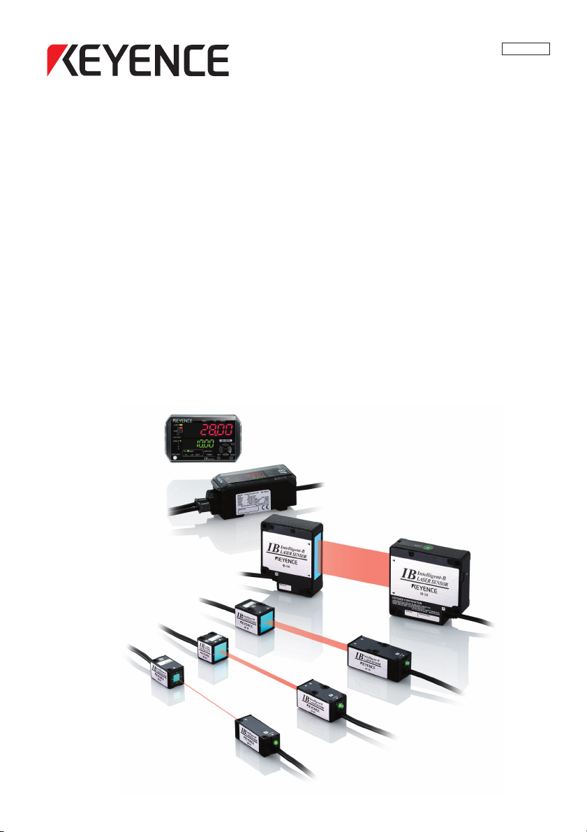
IB Series
User’s Manual
Read this manual before using the product in order to
achieve maximum performance.
Keep this manual in a safe place after reading it so that
it can be referenced at any time.
96099E
Thrubeam Type
Laser Detection Sensor
Page 2
Introduction
DANGER
WARNING
CAUTION
NOTICE
Important
Point
This manual describes the basic operations and information for the IB Series.
Read this manual carefully to ensure performance and safe function of the IB Series for safe
use.
Keep this manual in a safe place for future reference.
Make sure this manual is provided to the end user of this product.
Symbols
The following symbols are used in this manual to alert you to important matters for preventing
personal injury and device damage.
It indicates a hazardous situation which, if not avoided, will result in
death or serious injury.
It indicates a hazardous situation which, if not avoided, could result in
death or serious injury.
It indicates a hazardous situation which, if not avoided, could result in
minor or moderate injury.
It indicates a situation which, if not avoided, could result in product
damage as well as property damage.
It indicates cautions and limitations that must be followed during
operation.
It indicates additional information on proper operation.
Reference
It indicates tips for better understanding or useful information.
Reference pages are indicated.
Page 3
Safety Information for IB Series
WARNING
NOTICE
WARNING
Point
General Precautions
•
This product is just intended to detect object(s). Do not use this
product for the purpose of protecting a human body or a part of
human body.
•
This product is not intended for use as explosion-proof product. Do
not use this product in a hazardous location and/or potentially
explosive atmosphere.
•
Provide sufficient safety measures to prevent various damage in the
event this product fails.
•
When using this product in combination with other devices, there
may be cases when the functions and performance cannot be
achieved because of the working conditions or environment, etc.
Always review the combination carefully before starting use.
•
Do not apply sudden temperature changes on any device including the
peripheral devices. Condensation could cause device damage.
Safety Precautions on Laser Products
•
This product uses a semiconductor laser as a light source.
•
Use of controls or adjustments or performance of procedures other
than those specified herein may result in hazardous radiation
exposure.
•
Follow the instructions mentioned in this manual. Otherwise, injury
to the human body (eyes and skin) may result.
Precautions on Class 1 laser products
Do not stare into the beam.
•
•
Do not disassemble this product. Laser emission from this product
is not automatically stopped when it is disassembled.
Model IB-01/IB-05/IB-10/IB-30
Wavelength 660 nm
Output 170 μW
Pulse width 30 μs
FDA (CDRH) Part 1040.10
IEC60825-1 Class 1 Laser Product
* The classification is implemented based on IEC60825-1 following the requirement of Laser Notice No.50 of
FDA (CDRH).
Laser emission stop input
When laser emission stop input is set as an external input, laser
emission can be stopped by turning on the external input (2 ms or
more). Laser emission stays stopped while the external input is on.
The laser is emitted within 3 ms after the external input is turned off.
IB-E
*
Class 1 Laser Product
96099E
1
Page 4
WARNING
WARNING
CAUTION
NOTICE
Troubleshooting
Turn the power OFF immediately in the following cases. Continuing
use in an abnormal state can cause damage.
When water or foreign matter enters the product body
•
•
When the product has been dropped or the case damaged
•
When smoke or abnormal odors are emitted from the product
Precautions for Use
•
Use this product with the correct power voltage. Failure to do so
could result in fire or electric shock.
•
Do not disassemble or modify this product. Failure to observe this
could result in fire or electric shock.
•
Always turn off the power of the main unit and any device connected to
the main unit before connecting or disconnecting a cable.
•
Do not turn the power off while modifying device settings. Doing so
could result in the lost of some or all setting data.
Installation Environment
To ensure correct and safe use of this product, do not install it in the
following type of environment. Failure to observe this could result in
faults.
Location subject to high levels of moisture or dust, or which is
•
poorly ventilated
•
Location subject to high temperatures, such as where product is
subject to direct sunlight
•
Location subject to corrosive or flammable gases
•
Location directly subject to vibration or impact
•
Location subject to water, oil or chemical spray
•
Location where static electric is easily generated
Effect of Contaminants
•
Contaminants such as dirt, dust, water or oil may prevent a correct
measurement from being made.
•
Remove any contaminants from the transmitter and receiver
sections with clean air. If heavily contaminated, wipe the sections off
with a soft cloth soaked with alcohol.
•
Remove any contaminants from the measurement target with clean
air, or wipe them off.
•
If contaminants are suspended in the measurement range, install a
protective cover, or perform air purging, etc.
Measures for Noise
When installing this product near a source of noise such as a power
cable or high voltage cable, it could malfunction or fail because of
the noise. Provide measures for noise such as installing a noise
filter, laying the cables in a separate conduit, or insulating the
amplifier unit or sensor head.
2
IB-E
Page 5
NOTICE
Warming Up
WARNING
NOTICE
Wait at least 30 minutes after turning the power on before starting
use. The circuit will be unstable immediately after the power is
turned on so the display value may gradually fluctuate.
Power On Reset
Once the power is turned on, it will take approx. 2 seconds for the
measurement to start. The judgment output will be output after the
response time (average number of times x sampling rate) has elapsed.
Other Precautions
Power Supply
•
The product could malfunction due to noise superimposed on the
power supply. Use a DC stabilized power supply with insulated
transformer for the power supply.
•
When using a commercially-available switching regulator, always
ground the frame ground terminal.
Precautions on Regulations and Standards
CE Marking
Keyence corporation has confirmed that this product complies with
the essential requirements of the applicable EC Directives, based on
the following specifications. Be sure to consider the following
specifications when using this product in the Member States of
European Union.
EMC Directive
•
Applicable standards EMI: EN60947-5-2, Class A
These specifications do not guarantee that the end-product with this
product incorporated complies with the essential requirements of
the EMC Directives. The manufacturer of the end-product is solely
responsible for ensuring the compliance of the end-product.
Low-voltage Directive
•
Applicable standard: EN60825-1
UL Certification
This product is an UL/cUL Listed product.
•
UL File No. E301717
•
Category: NRKH, NRKH7
Be sure to consider the following specifications when using this
product as a UL/cUL Listed Product.
•
Use the power supply with Class 2 output defined in NFPA70 (NEC:
National Electrical Code).
•
The UL certificate for the IB series is for the sensor head and
amplifier used in combination. The IB series sensor head must be
used together with the IB series sensor amplifier unit exclusively.
•
Power supply/ Control input/ Control output shall be connected to a
single Class 2 source only.
•
Use with the over current protection device which is rated 30V or more
and not more than 1A.
•
Use this product under pollution degree 2.
EMS: EN60947-5-2
IB-E
3
Page 6

Table of Contents
Introduction
Safety Information for IB Series ................................................................ 1
General Precautions ................................................................................ 1
Safety Precautions on Laser Products..................................................... 1
Troubleshooting ....................................................................................... 2
Precautions for Use ................................................................................. 2
Other Precautions.................................................................................... 3
Precautions on Regulations and Standards............................................. 3
Chapter 1 Before Use
1-1 Checking the Package Contents ................................................... 1-2
Sensor Amplifier Unit ............................................................................ 1-2
Sensor Head ......................................................................................... 1-3
List of Optional Parts............................................................................. 1-4
1-2 Part Names and Functions............................................................ 1-5
Sensor Amplifier Unit ............................................................................ 1-5
Sensor Head Unit.................................................................................. 1-8
Chapter 2 Installation and Connection
2-1 Mounting and Wiring the Sensor Amplifier Unit............................. 2-2
Mounting the Sensor Amplifier Unit ...................................................... 2-2
Wiring the Sensor Amplifier Unit........................................................... 2-6
2-2 Connecting and Mounting the Sensor Head .................................2-8
Mounting the Sensor Head ................................................................... 2-8
Connecting the Sensor Head................................................................ 2-9
Chapter 3 Basic Operations
3-1 Operation when the Power Is Turned On for the First Time.......... 3-2
3-2 Operations on the Main Screens................................................... 3-3
R.V. (Internal Measurement Value) and P.V. (Judgment Value) .......... 3-3
Main Display (Upper Level)................................................................... 3-3
Sub Display (Lower Level).................................................................... 3-4
Setting Operations ................................................................................ 3-6
3-3 Beam Axis Adjustment .................................................................. 3-8
4
IB-E
Page 7

Beam Axis Adjustment Assistant Function ........................................... 3-8
3-4
Reference Light Registration (Gain Adjustment) and Adjust Function
Reference Light Registration (Gain Adjustment) ................................ 3-10
Adjust Function ................................................................................... 3-11
Cancelling the Adjust Function (Reset)............................................... 3-11
3-5 Initial Reset (Initialize)................................................................. 3-12
3-6 Setting the Tolerance Setting Value ........................................... 3-13
Manual Setting.................................................................................... 3-14
Automatic Setting................................................................................ 3-15
3-7
Zero Shift Function (Shifting the Internal Measurement Value (R.V.))
Setting the Shift Target Value............................................................. 3-18
Performing the Zero Shift.................................................................... 3-19
Canceling the Zero Shift (Reset)......................................................... 3-19
3-8
Bank Function (Registering Multiple Tolerance Setting Values)
Settings Registered with the Bank...................................................... 3-20
How to Switch the Bank...................................................................... 3-21
3-9 Key Lock Function ...................................................................... 3-23
Starting the Key Lock.......................................................................... 3-23
Canceling the Key Lock (Unlock)........................................................ 3-23
Chapter 4 Setting Various Functions
... 3-10
... 3-18
...... 3-20
4-1 Setting Operations ........................................................................ 4-2
4-2 Basic Settings and Advanced Settings ......................................... 4-4
List of Setting Items .............................................................................. 4-4
Setting Screen ...................................................................................... 4-6
1. Measurement Mode.......................................................................... 4-8
2. Received/Blocked Light Mode ........................................................ 4-10
3. Averaging/High-Pass Filter............................................................. 4-11
4. Output Mode ................................................................................... 4-13
5. Hold Function.................................................................................. 4-14
6. Timing Input .................................................................................... 4-23
7. Delay Timer..................................................................................... 4-23
8. Hysteresis ....................................................................................... 4-26
9. Analog Output Scaling .................................................................... 4-27
10. External Input................................................................................ 4-29
11. Bank Switching Method ................................................................ 4-35
12. Save Zero-Shift State.................................................................... 4-36
13. Save Adjust State ......................................................................... 4-36
IB-E
5
Page 8

14. Adjust Level .................................................................................. 4-37
15. Auto Adjust Function..................................................................... 4-37
16. Check Output Function ................................................................. 4-38
17. Error Output Mode ........................................................................ 4-39
18. Display Digit.................................................................................. 4-40
19. Power Save Function.................................................................... 4-40
20. Judgment Indicator Color.............................................................. 4-41
21. P.V. Value Display Color............................................................... 4-41
4-3 Calibration Function ....................................................................4-42
Setting Method (Measured Correction)............................................... 4-43
Setting Method (Logical Correction) ................................................... 4-45
Chapter 5 Specifications
5-1 Specifications ................................................................................ 5-2
Sensor Head ......................................................................................... 5-2
Amplifier Unit......................................................................................... 5-3
5-2 Circuit Diagram.............................................................................. 5-4
Output Circuit........................................................................................ 5-4
Analog Output Circuit............................................................................ 5-4
Input Circuit........................................................................................... 5-5
5-3 Dimensions.................................................................................... 5-6
Amplifier Unit......................................................................................... 5-6
Sensor Head ......................................................................................... 5-8
Chapter A Appendix
Troubleshooting .................................................................................... A-2
Frequently Asked Questions.................................................................A-2
Error Displays and Corrective Actions ..................................................A-4
Non-Error Related Displays and Countermeasures..............................A-7
Display Screen and Output................................................................... A-9
Factory Setting (Default Value) List .................................................... A-10
Index ................................................................................................... A-11
6
IB-E
Page 9

Before Use1
This chapter describes the overview of the IB Series and the name
and function of each part.
1-1 Checking the Package Contents.......................... 1-2
1-2 Part Names and Functions................................... 1-5
1
IB-E
1-1
Page 10
1
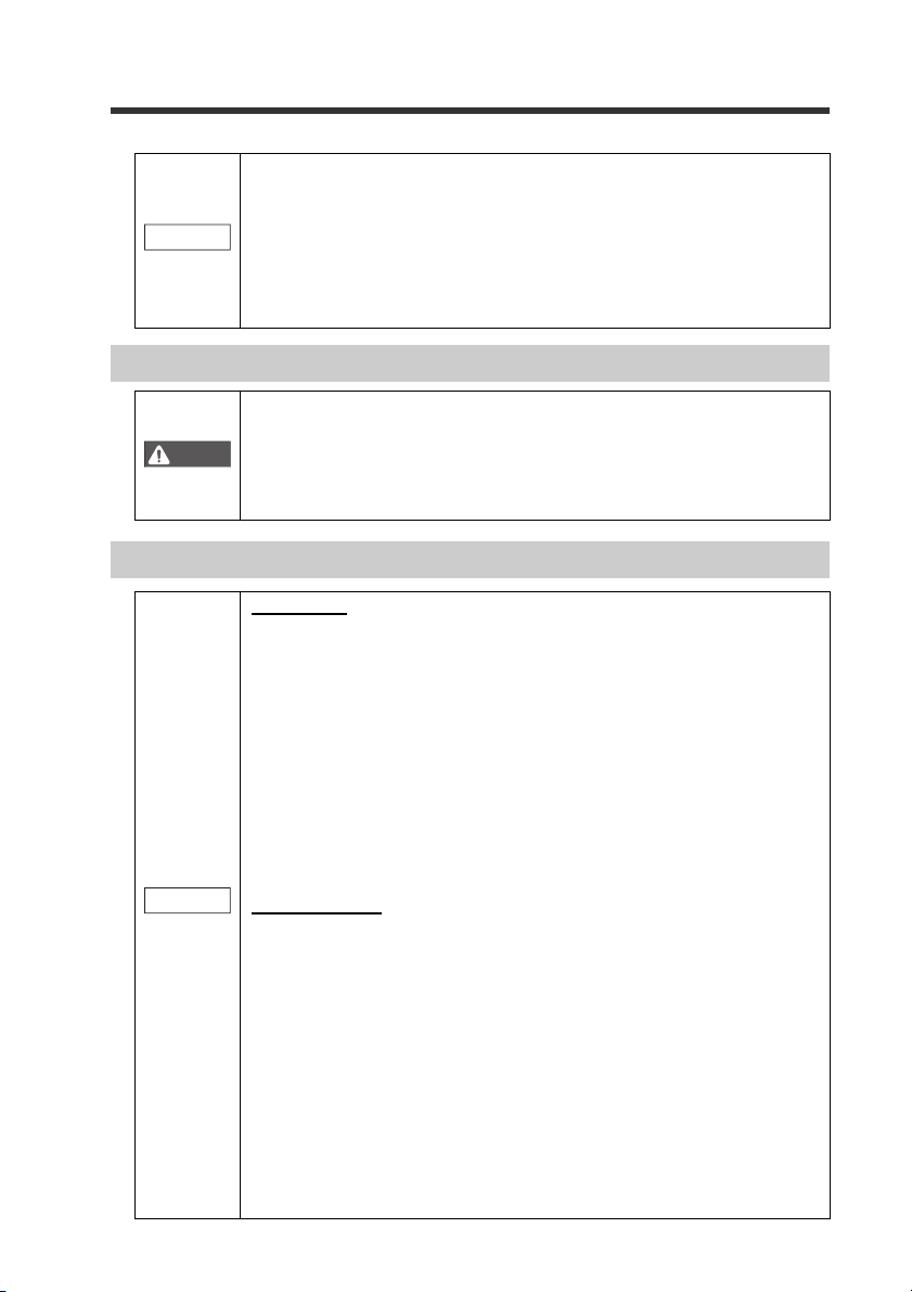
Amplifier x 1
Instruction manual x 1
Amplifier x 1
IB-1000 (main unit) IB-1050 (expansion unit)
IB-1500 (main unit)
Amplifier x 1 Panel mounting
bracket x 1
Front protection
cover x 1
Power/Input-output cable (2 m) x 1
(Number of cable cores: 12)
Instruction manual x 1
IB-1550 (expansion unit)
Amplifier x 1 Panel mounting
bracket x 1
Front protection
cover x 1
Power/Input-output cable (2 m) x 1
(Number of cable cores: 8)
Expansion cable
(50 mm) x 1
1-1 Checking the Package Contents
The following equipment and accessories are included in the package. Before using the
unit, make sure that all items are included.
We have thoroughly inspected the package contents before shipment. However, in the
event of defective or broken items, contact your nearest KEYENCE office.
Sensor Amplifier Unit
Before Use
DIN rail mount type
Panel mount type
1-2
IB-E
Page 11
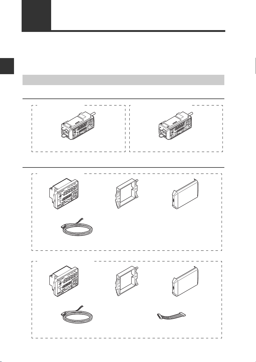
Sensor Head
R
.oN LA
IRES
R
ESAL
T
IB-01 (Measurement range φ1 to 2.5 mm)
Transmitter x 1 Receiver x 1
Mounting bracket x 2
Flat nut x 2
M3 x 20 mm screw x 4
RE
S
AL
T
R
.oN LAI
RES
IB-05 (Measurement range 5 mm)
Transmitter x 1 Receiver x 1
Mounting bracket x 2
Flat nut x 2
M3 x 25 mm screw x 4
IB-10 (Measurement range 10 mm)
Transmitter x 1 Receiver x 1
Mounting bracket x 2
M3 x 25 mm screw x 4
Flat nut x 2
LASER
IB-30 (Measurement range 30 mm)
Transmitter x 1 Receiver x 1
Mounting bracket x 2
M4 x 25 mm screw x 6
1-1 Checking the Package Contents
1
Before Use
AL
S
RE
T
IB-E
.oN LAIRES
R
1-3
Page 12
1-1 Checking the Package Contents
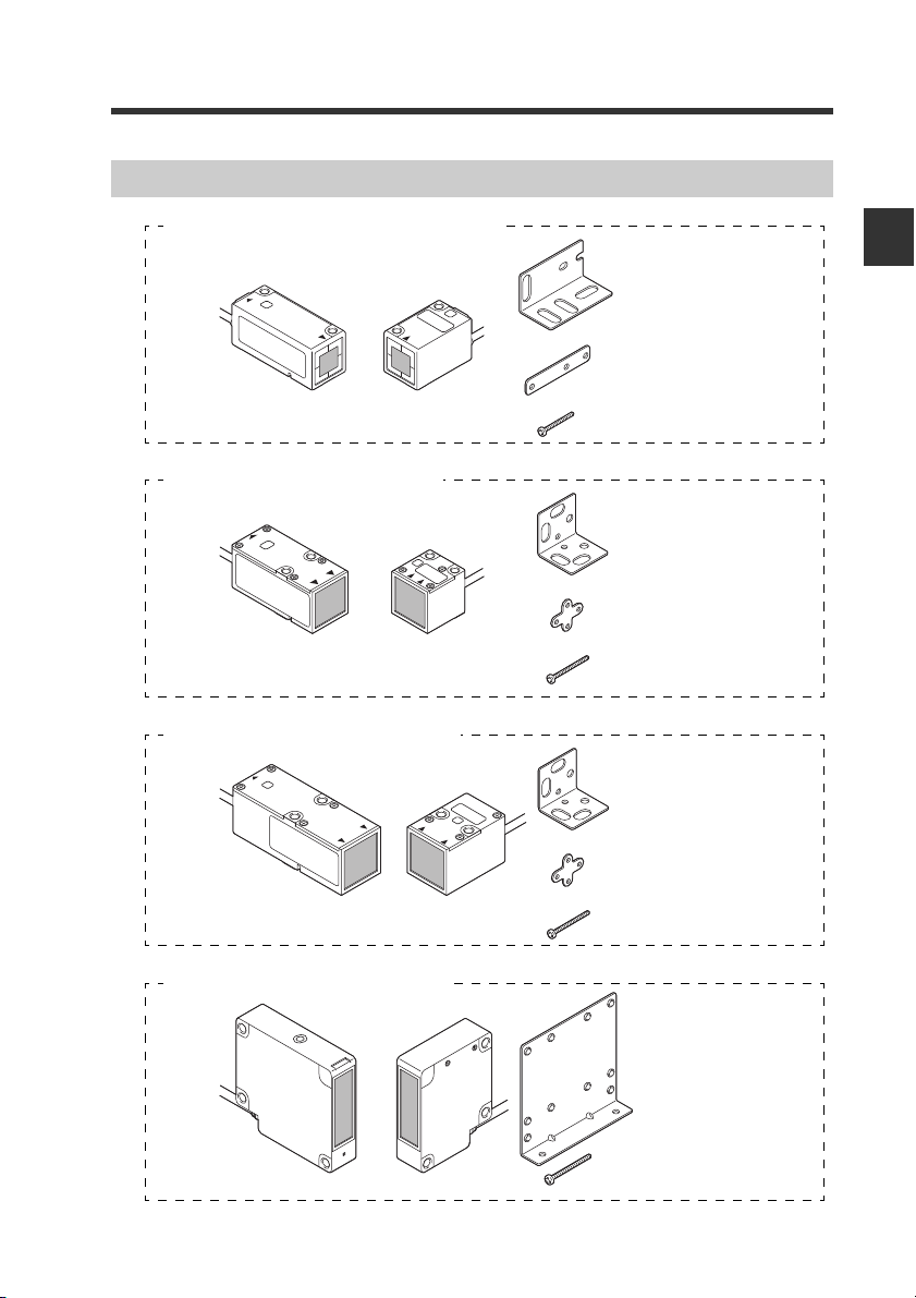
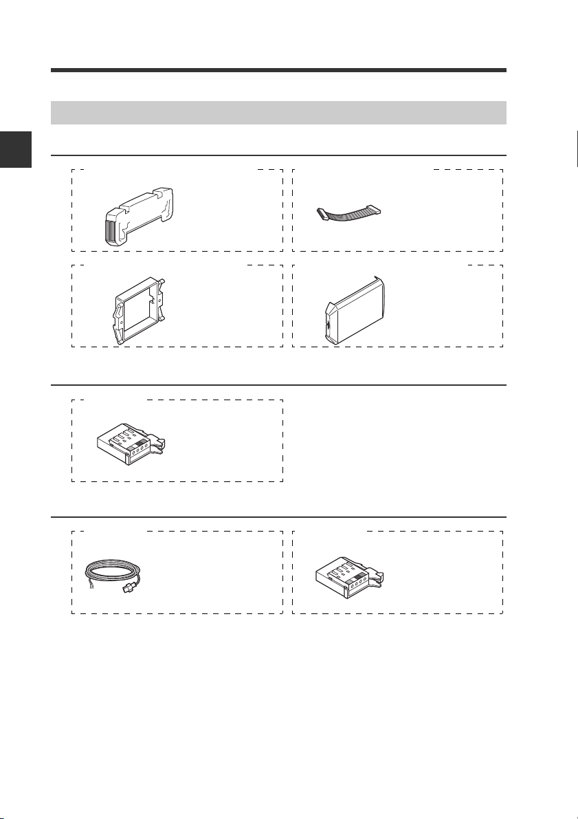
end unit
x 2
Expansion cable
(300 mm) x 1
OP-26751 (For IB-1000/IB-1050) OP-35361 (For IB-1550)
Panel mounting
bracket x 1
Front protection
cover x 1
OP-4122 (For IB-1500/IB-1550) OP-87076 (For IB-1500/IB-1550)
Sensor head
cable connector
x 2
OP-87060
Extension cable (17m) × 1
Accessory
• Female connector × 1
*Male connector is connected
Female connector x 1
Dust cover x 1
OP-87222 OP-87296
List of Optional Parts
1
For sensor amplifier unit
Before Use
For sensor head
Extension cable
1-4
IB-E
Page 13
1-2 Part Names and Functions
%HOLD
R.V.
HI
HI
LASER
GO
LOLOSHIFT
ANALOG ZERO SHIFT
Auto-ADJ
ZERO SHIFT
TIMING
BANK0
1
2
3
CHECK
SELECT
MODESET
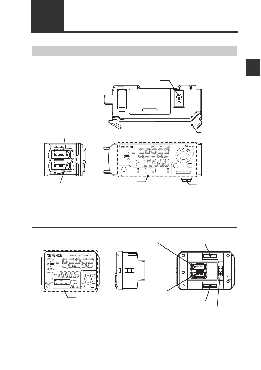
Expansion unit connector
*1
Amplifier control
unit cover
Sensor head connector (Transmitter)
Amplifier control unit
Sensor head connector (Receiver)
Expansion unit
connector
*2
Power/Input-output
cable connector
Expansion unit connector
(Upper)
*1
Expansion unit connector (Lower)*
2
Sensor head connector (Transmitter)
Sensor head connector (Receiver)
Amplifier control unit
Sensor Amplifier Unit
DIN rail mount type (IB-1000/IB-1050)
*1 When shipped from the factory, a protective cover is installed over the expansion
slots.
*2 It is not installed on the main unit (IB-1000).
Panel mount type (IB-1500/IB-1550)
1
Before Use
*1 It is not installed on the main unit (IB-1500).
*2 When shipped from the factory, a protective seal is attached.
IB-E
1-5
Page 14
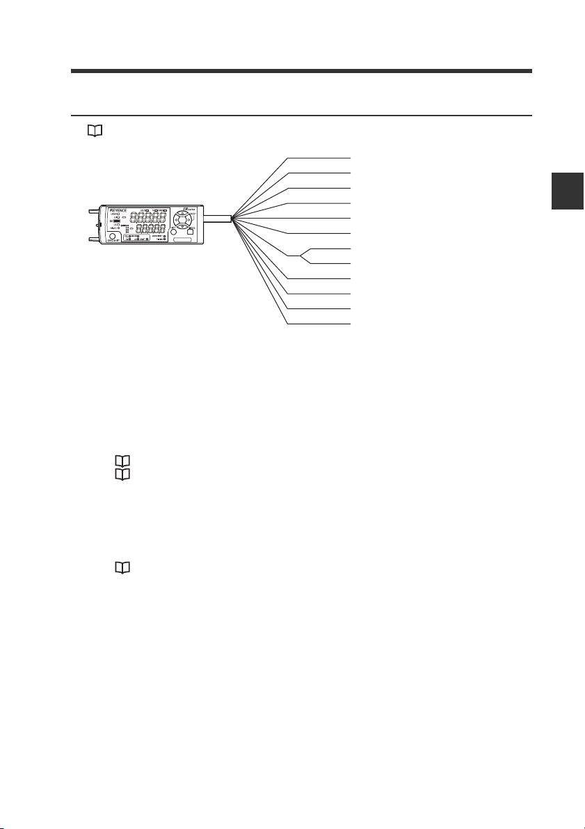
1-2 Part Names and Functions
(11) (12)(10)(6)
(16) (15) (14)
(1)
(2)
(3)
(4)
(5)
(7) (8) (9)
(13)
(11) (12)(10)(6)
(16) (15)
(14)
(1)
(2)
(3)
(4)
(5)
(7) (8) (9)
(13)
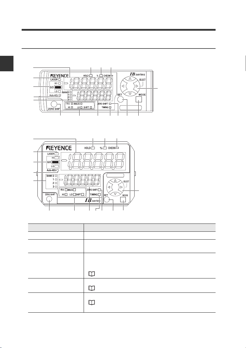
Amplifier control unit
DIN rail mount type (IB-1000/IB-1050)
1
Before Use
Panel mount type (IB-1500/IB-1550)
Item Description
(1) Main display Displays the judgment value (P.V.) and various setting items.
(2) Laser emission
warning indicator
(3) Judgment indicator
(4) Auto adjust indicator
(5) Bank indicator
Turns on while the laser beam is emitted. Flashes when laser
beam is stopped.
Indicates whether the judgment value (P.V.) in respect to the
tolerance setting is HIGH (higher than the upper limit), GO
(within tolerance range) or LOW (lower than the lower limit).
"3-6 Setting the Tolerance Setting Value" (page 3-13)
Turns on while the auto adjust function is operating.
" 15. Auto Adjust Function" (page 4-37)
Indicates the bank in use.
"3-8 Bank Function (Registering Multiple Tolerance Setting
Values)" (page 3-20)
1-6
IB-E
Page 15
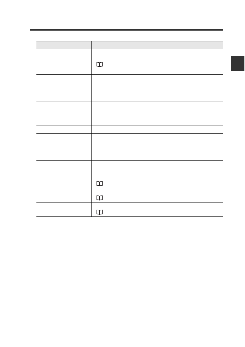
1-2 Part Names and Functions
Item Description
Press this to set the internal measurement value (R.V.) to the
(6) Zero shift button
(7) Sub display
identification indicator
(8) Sub display
(9) Timing input indicator
(10)Zero shift indicator Turns on for approx. 0.5 seconds when zero shift is executed.
(11)SET button
(12)MODE button
(13) Arrow buttons
(14) Check indicator
(15) Percentage indicator
(16)Hold indicator
shift target value.
"3-7 Zero Shift Function (Shifting the Internal Measurement
Value (R.V.))" (page 3-18)
Turns on according to the type of value displayed on the sub
display.
Displays the internal measurement value (R.V.), analog output
value and various settings (selections).
If the timing input (external input) is set to level, this indicator
lights while the timing input is on. If the timing input is set to
edge, this indicator turns on for approx. 0.5 seconds when the
timing input is on.
When making various settings, press this button to
automatically set the setting value.
When making various settings, press this button to start or end
the setting or to move the item.
Use this to select the setting item or to change the details
displayed on the sub display.
Turns on when the check output is on.
" 16. Check Output Function" (page 4-38)
Turns on when the measurement mode is % mode.
" 1. Measurement Mode" (page 4-8)
Turns on when the judgment value (P.V.) is held.
" 5. Hold Function" (page 4-14)
1
Before Use
IB-E
1-7
Page 16
1-2 Part Names and Functions
Point
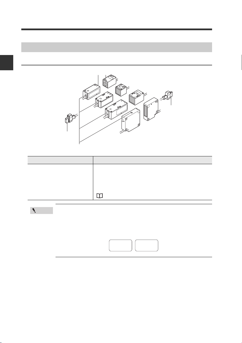
Laser receiverLaser transmitter
(1) Laser emission warning indicator
ReceiverTransmitter
Receiver head
connector
Transmitter head
connector
SERIAL No.
12345678
Receiver
No.
12345678
Transmitter
Sensor Head Unit
1
IB-01/IB-05/IB-10/IB-30
Before Use
(1) Laser emission warning
indicator
R
.oN L
A
IRES
R
T
ESAL
R
T
AL
S
RE
.oN LAIRES
.oN L
AIR
R
ES
T
RESAL
LASER
Item Description
Always on when the power is supplied to the sensor head.
Flashes while using the beam axis adjustment assistant
function. The flashing cycle quickens as the received
amount increases and can be uses as a guide for adjusting
the beam axis.
" Beam Axis Adjustment Assistant Function" (page 3-8)
Use a transmitter and receiver with the same serial No. combination.
The operation and accuracy cannot be guaranteed if units with
different serial numbers are used in combination. The serial No. is
attached to the top of the transmitter and receiver.
1-8
IB-E
Page 17

Installation and Connection2
This chapter describes precautions when installing and connecting
the IB Series.
2-1 Mounting and Wiring the Sensor Amplifier Unit 2-2
2-2 Connecting and Mounting the Sensor Head....... 2-8
2
IB-E
2-1
Page 18
2
(1)
(2)
(3)
CAUTION
Point
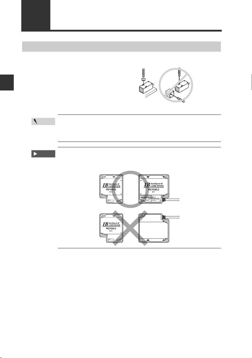
2-1 Mounting and Wiring the Sensor Amplifier Unit
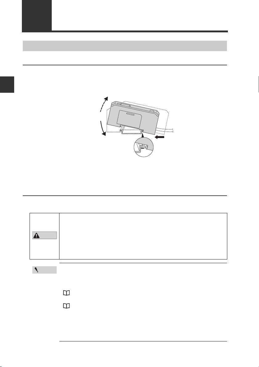
Mounting the Sensor Amplifier Unit
DIN rail mount type, main unit (IB-1000)
Align the claw at the bottom of the main body with the DIN rail. While
1
pushing the main body in the direction of the arrow (1), tilt the amplifier in
the direction of the arrow (2).
Installation and Connection
To remove the amplifier, raise the main body in the direction of the arrow
2
(3) while pushing it in the direction of the arrow (1).
DIN rail mount type, expansion unit (IB-1050)
Expansion units must be connected to the main unit before they can be used.
Up to 3 expansion units can be connected to one main unit.
• When connecting multiple amplifiers (expansion units), first check
to make sure that the power is turned off to all of the main and
expansion units. Installing an expansion unit with power on may
damage this device.
• Push the amplifiers (expansion units) as far as possible into the
main unit. If they are connected at an angle or not inserted
securely, this device could get damaged.
2-2
• When connecting the expansion units, make sure to initialize the
expansion units and set the output polarity.
(1) When turning on the amplifier for the first time after connecting
the sensor head please reference
"3-1 Operation when the Power is Turned On for the First Time" (page 3-2)
(2) When initializing the unit please reference
"3-5 Initial Reset (Initialize)" (page 3-12)
• Expansion units with different settings for output polarity (such as
an NPN output expansion unit to a PNP output main unit) cannot
be connected together.
• Expansion units using DIN rail mount cannot be connected to a
panel mount style main unit.
IB-E
Page 19
2-1 Mounting and Wiring the Sensor Amplifier Unit
Point
Connector cover
Main unit
End unit
End unit
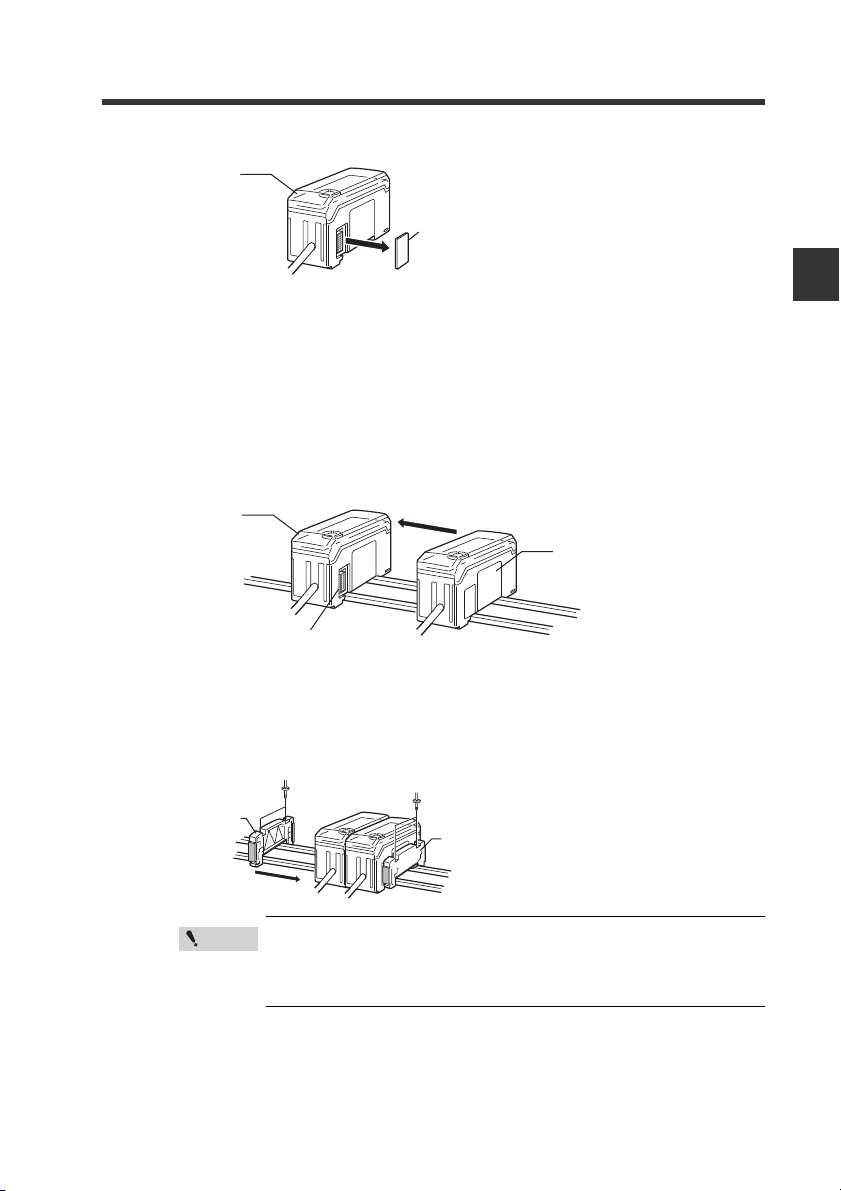
Remove the expansion protective cover from the IB-1000 (main unit).
1
Install the amplifiers (expansion units) onto the DIN rail.
2
Do the same as instructed under “DIN rail mount type, main unit.”
Push the expansion unit into the main unit connector until a clicking
3
sound can be heard.
The expansion unit installed next to the main unit is referred to as expansion unit 1.
Subsequent expansion units are referred to as expansion unit 2, expansion unit 3,
and so on.
Main unit
Expansion
unit
Connecter
2
Installation and Connection
IB-E
Install the end units (OP-26751: 2 units per set) (sold separately) on both
4
sides of the amplifiers (main or expansion units). Secure the end units in
place with screws on top (2 on each end unit).
The end units are mounted in the same way as the amplifiers.
Mount the amplifiers securely using the end units (OP-26751: 2
units per set) (sold separately) or a commercially available DIN
rail mounting tool to prevent the amplifiers from slipping and
coming off from the DIN rail due to machine vibration.
2-3
Page 20
2-1 Mounting and Wiring the Sensor Amplifier Unit
Minimum
85 mm
45 mm
45 mm
+ 0.6
- 0
+ 0.6
- 0
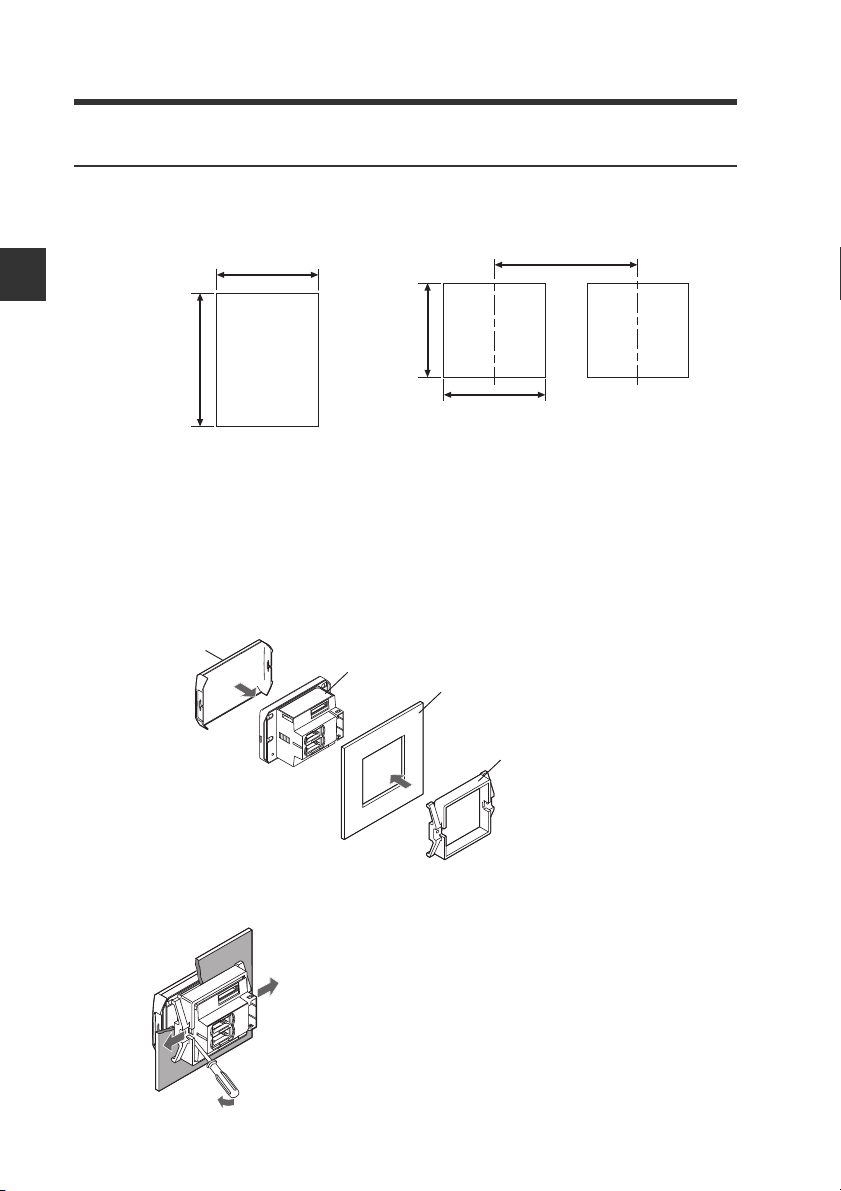
Panel mount type, main unit (IB-1500)
Make a hole on the panel as shown in the diagrams below.
1
When stacking the units vertically When stacking the units horizontally
+ 0.6
45 mm
- 0
2
Installation and Connection
X mm
• Panel thicknes 1 to 6 mm
• X = 48 x (Number of amplifiers) - 3
Insert the back side of amplifier to the hole of the panel.
2
Arrange the panel mounting tool in the direction below, mount to the
3
amplifier from the back and attach the front protection cover to the
amplifier.
Front protection
cover
Amplifier
Panel
2-4
Panel mounting
bracket
To remove the panel mounting tool, widen the claws at both ends of the panel
mounting tool using a screwdriver, as illustrated below.
IB-E
Page 21

2-1 Mounting and Wiring the Sensor Amplifier Unit
CAUTION
Point
Reference
Panel mount type, expansion unit (IB-1550)
Several expansion units can be used in connection with the main unit. Up to 3 expansion
units can be connected to one main unit.
• When connecting the expansion cable, make sure to turn off the
power beforehand. Inserting or removing the cable with the power
turned on may cause damage to the units.
• Push the expansion cable connector securely all the way. If it is
connected at an angle or not inserted securely, the units could get
damaged.
• When connecting the expansion units, make sure to initialize the
connected expansion units and set the output polarity.
(1) When turning on the amplifier for the first time after connecting
the sensor head
"3-1 Operation when the Power is Turned On for the First Time" (page 3-2)
(2) When initializing the unit
"3-5 Initial Reset (Initialize)" (page 3-12)
• Expansion units with different settings for output polarity (such as
an NPN output expansion unit to a PNP output main unit) cannot
be connected together.
• Expansion units using panel mount cannot be connected to a DIN
rail mounted main unit.
Make the appropriate number of holes in the panel according to the
1
number of amplifiers required (expansion units).
For the panel cutting measurement, refer to “Panel mount type, main unit”.
Install the amplifiers (expansion units) on the panel.
2
For the amplifier mounting method, refer to “Panel mount type, main unit”.
Connect the amplifiers (main and expansion units) using the expansion
3
cable (50 mm) supplied with the expansion unit.
The expansion unit installed next to the main unit is referred to as expansion unit 1.
Subsequent expansion units are referred to as expansion unit 2, expansion unit 3,
and so on.
2
Installation and Connection
IB-E
Main unit
Expansion cable
Expansion unit
When arranging the amplifiers side by side, the 300 mm expansion cable
(OP-35361) is required.
2-5
Page 22
2-1 Mounting and Wiring the Sensor Amplifier Unit
Point
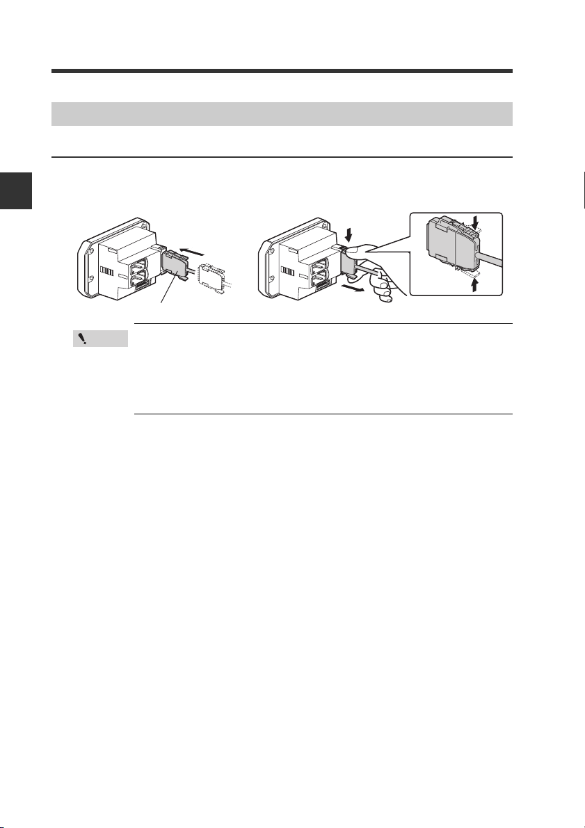
Power/Input-output cable
To attach To remove
Wiring the Sensor Amplifier Unit
Connecting the power/input-output cable (for panel mount type only)
Connect the power/input-output cable to the panel mount type main unit and the input/
output cable to the expansion unit.
2
Installation and Connection
• The number of core wires for the power/input-output cable for the
main unit is 12, and the number of core wires for the input-output
cable for the expansion units is 8.
• Power for the expansion units is supplied from the main unit.
• When not using the I/Os of expansion unit, cut the cable near the
connector.
2-6
IB-E
Page 23
2-1 Mounting and Wiring the Sensor Amplifier Unit
Power/Input-output cable
"Output Circuit" (page 5-4)
*1
Brown
*1
Light blue
Orange
Shield
Yellow
Pink/Purple
Purple
*1 IB-1050/IB-1550 (expansion units) do not have brown, blue or light blue wires. Power
is supplied to the expansion units through IB-1000/IB-1500 (main unit).
*2 The analog output can be set to any of the following options either “when the power is
turned on for the first time” or “when performing the initial reset”.
• Not used (OFF)
•0 to 5 V
• -5 to 5 V
•1 to 5 V
• 4 to 20 mA
"3-1 Operation when the Power is Turned On for the First Time" (page 3-2)
"3-5 Initial Reset (Initialize)" (page 3-12)
*3 The external input can be selected among the following in addition to the above.
• Bank A input
• Bank B input
• Laser emission stop input
• Not used (OFF)
Adjust input can be selected only for the external input 4.
"10. External Input" (page 4-29)
10 to 30 VDC
*1
Blue
0 V
Black
HIGH judgment output
White
LOW judgment output
Gray
GO judgment output
Green
Check output
*2
Analog output +
*2
Analog output GND
*3
Pink
External input 1 (Zero shift input)
*3
External input 2 (Reset input)
*3
External input 3 (Timing input)
*3
External input 4 (Not used)
2
Installation and Connection
IB-E
2-7
Page 24
2
Point
Important
Installation and Connection
2-2 Connecting and Mounting the Sensor Head
Mounting the Sensor Head
Mounting
Mount the sensor head with the
enclosed screws (IB-01/IB-05/IB-10:
M3, IB-30: M4).
Tightening torque: 0.3 N·m or less
(Tightening torque for IB-01: 0.1 N·m
or less)
• Always use mounting holes facing the same direction for the
sensor head transmitter and receiver. (Excluding IB-01)
• Do not tighten the screws with a torque exceeding 0.3 N·m. The
sensor head could deform, thus preventing beam axis alignment.
When mounting the sensor, confirm that the transmitter and receiver
faces on which the nameplate label is attached are facing the same
direction. (Only for IB-30)
2-8
IB-E
Page 25

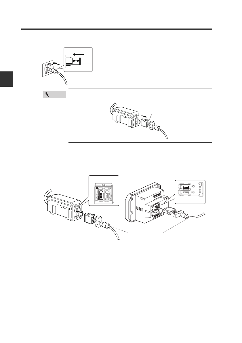
2-2 Connecting and Mounting the Sensor Head
Unlocked
Lock cover
Click
Connecting the Sensor Head
Connecting the sensor head and sensor amplifier unit
Attach the receiver’s sensor head connection cable to the amplifier’s [R]
1
connector.
Remove the lock cover of the connector and
insert it into the connectors of amplifier until a
clicking sound can be heard.
2
Installation and Connection
DIN rail mount type
(IB-1000/IB-1050)
Panel mount type
(IB-1500/IB-1550)
Right side is [R] side
Bottom is [R] side
Blue ring
IB-E
2-9
Page 26
2-2 Connecting and Mounting the Sensor Head
Point
Lock lever
Top is [T] side
Red ring
Left is [T] side
Attach the lock cover to the connector to secure the cable.
2
Lock cover
Locked
2
Installation and Connection
When removing the sensor head connection cable, push
the lock lever and pull it out.
Attach the transmitter’s sensor head connection cable to the amplifier’s
3
[T] connector.
DIN rail mount type
(IB-1000/IB-1050)
The connection procedures are the same as the receiver side.
Panel mount type
(IB-1500/IB-1550)
2-10
IB-E
Page 27
2-2 Connecting and Mounting the Sensor Head
Point
Point
Blue Black
White Brown
Insert further
than here.
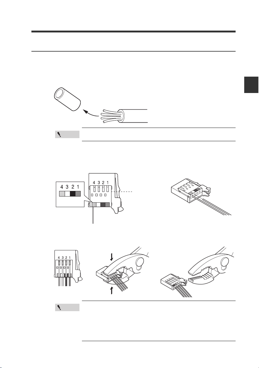
Attaching the sensor head cable connector (OP-87060)
Cut the sensor head cable to the required length and attach the new connector to use the
sensor. The connection method is the same for the transmitter and receiver.
Cut the cable to the required length and strip approx. 15 mm of insulation
1
from the end.
Do not strip the core wire insulation.
Insert each color coded cable into the same colored marked points on the
2
connector.
Each cable is secured temporarily when it is inserted completely.
2
Installation and Connection
IB-E
Confirm that all the cables are inserted properly into the connector and
3
crimp them using pliers or a similar tool.
Once the connector has been installed, make sure to connect
it to the amplifier and confirm that the sensor operates
normally.
If the sensor head does not function properly, crimp the
connector again using pliers or a similar tool.
Once the connector is crimped, it cannot be reused.
2-11
Page 28

2-2 Connecting and Mounting the Sensor Head
2
Installation and Connection
MEMO
2-12
IB-E
Page 29

Basic Operations3
This chapter describes basic operations and settings for the IB
Series.
3-1 Operation when the Power is Turned On for the
First Time ............................................................... 3-2
3-2 Operations on the Main Screens ......................... 3-3
3-3 Beam Axis Adjustment......................................... 3-8
3-4 Reference Light Registration (Gain Adjustment) and
Adjust Function ................................................... 3-10
3-5 Initial Reset (Initialize)......................................... 3-12
3-6 Setting the Tolerance Setting Value .................. 3-13
3-7 Zero Shift Function (Shifting the Internal
Measurement Value (R.V.)) ................................. 3-18
3-8 Bank Function (Registering Multiple Tolerance
Setting Values)..................................................... 3-20
3-9 Key Lock Function.............................................. 3-23
3
IB-E
3-1
Page 30
3
Point
Power ON
PRP
LASER
BANK
0
1
2
3
HI
LO
R.V.
ANALOG
HI SHIFT
ZERO SHIFT
TIMING
LO
ALIGNMENT
QWV
GO
HOLD CALC
CHECK
Output polarity
Setting value Description
npn
NPN output
pnp
PNP output
QHH
LASER
BANK
0
1
2
3
HI
LO
R.V.
ANALOG
HI SHIFT
ZERO SHIFT
TIMING
LO
ALIGNMENT
#P.)
GO
HOLD CALC
CHECK
Analog output
Setting value Description
off
Not output
0-5u
Analog output after the judgment value is converted to
the range from 0 to 5 V.
-5-5u
Analog output after the judgment value is converted to
±5 V.
1-5u
Analog output after the judgment value is converted to
the range from 1 to 5 V.
aMpr
Analog output after the judgment value is converted to
the range from 4 to 20 mA.
LASER
BANK
0
1
2
3
HI
LO
R.V.
ANALOG
HI SHIFT
ZERO SHIFT
TIMING
LO
ALIGNMENT
GO
HOLD CALC
CHECK
'PF
Basic Operations
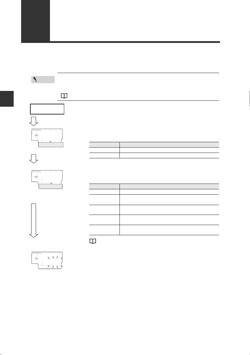
3-1 Operation when the Power is
Turned On for the First Time
When the amplifier is turned on for the first time after the sensor head is connected, the
initial setting display appears. Make the initial setting according to the following procedure
as this is necessary for both the main unit and the expansion units when units are added.
Once the initial setting is completed, the initial setting display will
not appear when the power is turned on the second time or the after.
To change the initial setting, perform the initial reset.
"3-5 Initial Reset (Initialize)" (page 3-12)
Select the judgment output and check output polarity
1
with the / button, and press the [MODE] button.
[MODE] button
Press the / button to select the analog output
2
method and press the [MODE] button.
[MODE] button
3
Carry out "3-3 Beam Axis Adjustment" (page 3-8) and "3-4 Reference
4
Light Registration (Gain Adjustment) and Adjust Function" (page 3-10).
Make other settings as necessary.
3-2
"9. Analog Output Scaling" (page 4-27)
After the setting is complete, [end] blinks several
times on the sub display and changes to the main
screen.
IB-E
Page 31

3-2 Operations on the Main Screens
LASER
BANK
0
1
2
3
HI
GO
LO
R.V.
ANALOG
HI SHIFT
ZERO SHIFT
TIMING
LO
ALIGNMENT
HOLD CALC
CHECK
LASER
BANK
0
1
2
3
HI
LO
R.V.
ANALOG
HI SHIFT
ZERO SHIFT
TIMING
LO
ALIGNMENT
[HOLD] ON
GO
HOLD CALC
CHECK
R.V. (Internal Measurement Value) and P.V. (Judgment Value)
This section describes R.V. (Internal Measurement Value) displayed on the sub display
(lower level) and P.V. (Judgment Value) displayed on the main display (upper level).
R.V. (Internal Measurement Value)
R.V. (Internal Measurement Value) is the value displayed when a target is inserted into the
measurement range.
* R.V. = Raw Value
P.V. (Judgment Value)
P.V. (Judgment Value) is the value to set the judgment output to ON/OFF according to the
tolerance setting value. Also, the analog output is output based on the P.V.
* P.V. = Present Value
"3-6 Setting the Tolerance Setting Value" (page 3-13)
The judgment value (P.V.) and the internal measurement value (R.V.) are basically the
same, however, those values differ only when the hold function is used.
"5. Hold Function" (page 4-14)
Main Display (Upper Level)
The judgment value (P.V.) is displayed on the main display.
The display varies as below according to whether the hold function is used or not.
Normal
The same value as the internal measurement value (R.V.) is displayed
as a judgment value (P.V.).
When the hold function is used
The judgment value (P.V.) is held according to the hold function setting.
"5. Hold Function" (page 4-14)
3
Basic Operations
IB-E
3-3
Page 32

3-2 Operations on the Main Screens
GO
HOLD CALC
CHECK
LASER
BANK
0
1
2
3
HI
LO
R.V.
ANALOG
HI SHIFT
ZERO SHIFT
TIMING
LO
ALIGNMENT
LOW setting value
[LO]
ON
GO
LASER
BANK
0
1
2
3
HI
LO
R.V.
ANALOG
HI SHIFT
ZERO SHIFT
TIMING
LO
ALIGNMENT
HOLD CALC
CHECK
[HI]
ON
HIGH setting value
GO
HOLD CALC
CHECK
LASER
BANK
0
1
2
3
HI
LO
R.V.
ANALOG
HI SHIFT
ZERO SHIFT
TIMING
LO
ALIGNMENT
Shift target value
[SHIFT
]
ON
LASER
BANK
0
1
2
3
HI
LO
R.V.
ANALOG
HI SHIFT
ZERO SHIFT
TIMING
LO
ALIGNMENT
HOLD CALC
CHECK
GO
R.V.
[R.V.]
ON
W
LASER
BANK
0
1
2
3
HI
LO
R.V.
ANALOG
HI SHIFT
ZERO SHIFT
TIMING
LO
ALIGNMENT
HOLD CALC
CHECK
GO
Analog output
[ANALOG]
ON
(1) R.V. value display screen
* Displayed only for the
main unit and when the
analog output is used.
(2) Analog output screen
(5) Shift target value
setting screen
(3) HIGH setting
value screen
(4) LOW setting
value screen
Sub Display (Lower Level)
The sub display can be switched with the arrow button / .
According to the type of displayed value, the sub display indicator [R.V. / ANALOG / HI / LO /
SHIFT] lights up.
3
Basic Operations
3-4
IB-E
Page 33

3-2 Operations on the Main Screens
(1) R.V. value display screen
The internal measurement value (R.V.) is displayed. The displayed value is not held.
(2) Analog output screen (Displayed when using main unit’s analog output)
The voltage value (unit: V) or current value (unit: mA) of the analog output is displayed.
"3-1 Operation when the Power is Turned On for the First Time" (page 3-2)
"3-5 Initial Reset (Initialize)" (page 3-12)
(3) HIGH setting value screen
The upper limit of the acceptable range (tolerance setting value) for the object is
displayed. Also, the setting value can be changed. If the judgment value (P.V.) exceeds
the value set here, the HIGH judgment output turns on.
"3-6 Setting the Tolerance Setting Value" (page 3-13)
(4) LOW setting value screen
The lower limit of the acceptable range (tolerance setting value) for the object is
displayed. Also, the setting value can be changed. If the judgment value (P.V.) falls
below the value set here, the LOW judgment output turns on.
"3-6 Setting the Tolerance Setting Value" (page 3-13)
(5) Shift target value screen
When the zero shift button is pressed or the zero shift input is set to ON, the internal
measurement value (R.V.) is adjusted to the value set here.
"3-7 Zero Shift Function (Shifting the Internal Measurement Value (R.V.))" (page 3-18)
3
Basic Operations
IB-E
3-5
Page 34

3-2 Operations on the Main Screens
%HOLD
R.V.
HI
HI
LASER
GO
LO
LO
SHIFT
ANALOG ZERO SHIFT
Auto-ADJ
ZERO SHIFT
TIMING
BANK0
1
2
3
CHECK
SELECT
MODE SET
Buttons used
LASER
BANK
0
1
2
3
HI
GO
LO
R.V.
ANALOG
HI SHIFT
ZERO SHIFT
TIMING
LO
ALIGNMENT
HOLD CALC
CHECK
Setting Operations
This section explains functions selectable from the main screen and functions selectable after
the display changes to each setting screen.
Functions available on the main screen
3
DIN rail mount type (IB-1000/IB-1050)
Basic Operations
Main screen
3-6
Panel mount type (IB-1500/IB-1550)
Press the or button.
Switching display on the sub display (lower level) (page 3-4)
Any of the internal measurement value (R.V.), analog output
value, HIGH setting value, LOW setting value or shift target
value are displayed and the settings can be changed.
3-6 Setting the Tolerance Setting Value (page 3-13)
HIGH setting value and LOW setting value are set. The
judgment is made among HIGH/GO/LOW, and the value is
displayed and output.
3-7 Zero Shift Function (Shifting the Internal Measurement
Value (R.V.)) (page 3-18)
The internal measurement value (R.V.) can be shifted (offset)
to an arbitrary shift target value.
While pressing down the [MODE] button, press the or button.
3-8 Bank Function (Registering Multiple Tolerance Setting
Values) (page 3-20)
HIGH setting value, LOW setting value, and shift target value
can be saved at up to four banks and switched.
Press the [MODE] and [SET] buttons for approx. 2 seconds.
(Reference light registration)
or
Press the and buttons simultaneously. (Adjust function)
3-4 Reference Light Registration (Gain Adjustment) and
Adjust Function (page 3-10)
To ensure measurement stability, make sure to perform
“reference light registration (gain adjustment)” when using
the sensor for the first time or each time the sensor head
mounting position has been changed, etc.
Press the [MODE] and buttons for approx. 2 seconds.
or
Press the [MODE] and buttons for approx. 2 seconds.
3-9 Key Lock Function (page 3-23)
This function prevents unwanted button operations during
measurement.
IB-E
Page 35

Functions available on the setting screen
LASER
BANK
0
1
2
3
HI
GO
LO
R.V.
ANALOG
HI SHIFT
ZERO SHIFT
TIMING
LO
ALIGNMENT
HOLD CALC
CHECK
Main screen
Press the [MODE] button for approx. 2 seconds.
4-2 Basic Settings and Advanced Settings (page 4-4)
Basic settings
Basic settings, such as measurement mode and averaging,
are made.
Advanced settings
More advanced settings such as hold function, delay timer
enable the unit to be used in more complex applications.
Press the [MODE] and buttons for approx. 2 seconds.
4-3 Calibration Function (page 4-42)
When there is a difference between the internal
measurement value (R.V.) or calculated value (CALC value)
and the actual dimension of the object, the value can be
calibrated.
While pressing the [MODE] button, press the [SET] button 5
times.
3-5 Initial Reset (Initialize) (page 3-12)
All settings, excluding the calibration function, are initialized.
Press the and buttons for approx. 2 seconds.
3-3 Beam Axis Adjustment (page 3-8)
This function assists adjusting the laser beam’s axis.
3-2 Operations on the Main Screens
3
Basic Operations
IB-E
3-7
Page 36

3-3 Beam Axis Adjustment
Reference
1
LASER
BANK
0
1
2
3
HI
LO
R.V.
ANALOG
HI SHIFT
ZERO SHIFT
TIMING
LO
ALIGNMENT
#.K)P
GO
HOLD CALC
CHECK
Received light
Transmitter
Receiver
1
LASER
BANK
0
1
2
3
HI
LO
R.V.
ANALOG
HI SHIFT
ZERO SHIFT
TIMING
LO
ALIGNMENT
#.K)P
GO
HOLD CALC
CHECK
Beam axis is misaligned.
Transmitter
Receiver
1
LASER
BANK
0
1
2
3
HI
LO
R.V.
ANALOG
HI SHIFT
ZERO SHIFT
TIMING
LO
ALIGNMENT
#.K)P
GO
HOLD CALC
CHECK
Beam axis is aligned.
Adjust the laser beam’s axis.
Mount the receiver so that the transmitter and receiver are on the same
1
line.
With no object set in the detection area, move the transmitter and mount it
2
where the display value is the largest.
Receiver
3
Transmitter
Basic Operations
The beam axis does not need to be adjusted if the base of the sensor head
and the left side of the receiver looking from the transmitter are installed on
the same reference surface.
Beam Axis Adjustment Assistant Function
The IB Series has a beam axis adjustment assistant function which makes it easy to adjust
the beam axis.
The beam axis can be adjusted easily with the help of the amplifier unit’s display and
sensor head laser emission warning indicator.
Press the / buttons on the main screen simultaneously for 2 seconds,
1
and display the received light on the sub display (lower level).
With no object in the detection area, move the transmitter and mount the
2
transmitter and receiver so that the displayed received light is the largest.
3-8
IB-E
Page 37

3-3 Beam Axis Adjustment
Reference
Laser emission warning indicator
LASER
R
.oN LAIRES
RE
S
AL
T
RESAL
T
R
.oN
L
AIRES
R
.oN L
A
IRES
R
ESAL
T
When the beam axis is aligned, the value on the sub display (lower level) will increase.
Mount the units where the value is the largest when possible.
At this time, the laser emission warning
indicator on the sensor head will turn off or
blink. The indicator’s flashing cycle quickens
as the received light increases.
Adjust the beam axis together with the
received light level on the sub display (lower
level).
3
Basic Operations
Laser emission
warning indicator
Description Status drawing
State when laser beam is
Off
Blink (slow)
* Axis beam is deviated.
not transmitted into
receiver.
Off
Blink (slow)
Blink (fast)
*
Axis beam is
approximately aligned.
Blink (fast)
* The blinking cycle changes in stages. The faster the indicator blinks, the more accurate
the beam axis alignment is.
The main screen will reappear when any button on the amplifier unit is
3
pressed.
All judgment outputs turn off while using the beam axis adjustment assistant
function. The analog voltage output is fixed to 5.5 V and the analog current
output is fixed to 3.0 mA.
IB-E
3-9
Page 38

3
Point
Q-
LASER
BANK
0
1
2
3
HI
LO
R.V.
ANALOG
HI SHIFT
ZERO SHIFT
TIMING
LO
ALIGNMENT
)#KP
GO
HOLD CALC
CHECK
Registration completed
3-4
Reference Light Registration (Gain Adjustment) and Adjust Function
The amount of received light when the sensor head is mounted for the first time is
registered as the reference light.
If the incoming state of the laser beam changes during use because the front of the sensor
head is dirty, etc., the adjust function can be used to calibrate the light to the “reference
light” registered at the start of use. The adjust function can also be executed with external
inputs.
"10. External Input" (page 4-29)
Reference Light Registration (Gain Adjustment)
Basic Operations
Perform “reference light registration (gain adjustment)” when using the sensor for the first
time or each time the sensor head mounting position has been changed, etc.
Press the [MODE] and [SET] buttons simultaneously for 2 seconds.
[GAin] will display on the main display (upper level), and the reference light will be
registered. When the registration is completed, [oK] will flash a few times on the sub
display (lower level), and then the main screen will reappear.
3-10
•
The reference light cannot be registered with external inputs. Always
use the buttons on the main unit.
•
The following error displays will appear when the light is insufficient
or there is an interfering light.
LASER
GO
ALIGNMENT
HI
LO
BANK
HOLD CALC
'T)
0
1
2
3
ANALOG
R.V.
HI SHIFT
LO
F#T-
ZERO SHIFT
TIMING
CHECK
LASER
GO
ALIGNMENT
HI
LO
BANK
HOLD CALC
'T)
0
1
2
3
ANALOG
R.V.
HI SHIFT
LO
KP(
ZERO SHIFT
TIMING
CHECK
Light insufficient Interfering light
"Error Displays and Corrective Actions" (page A-4)
Press the [MODE] button to remove the error and return to the
main screen.
IB-E
Page 39

3-4 Reference Light Registration (Gain Adjustment) and Adjust Function
Point
Q-
LASER
BANK
0
1
2
3
HI
LO
R.V.
ANALOG
HI SHIFT
ZERO SHIFT
TIMING
LO
ALIGNMENT
#F,
GO
HOLD CALC
CHECK
Registration completed
F#T-
LASER
BANK
0
1
2
3
HI
LO
R.V.
ANALOG
HI SHIFT
ZERO SHIFT
TIMING
LO
ALIGNMENT
'T#F,
GO
HOLD CALC
CHECK
QX'T
LASER
BANK
0
1
2
3
HI
LO
R.V.
ANALOG
HI SHIFT
ZERO SHIFT
TIMING
LO
ALIGNMENT
'T#F,
GO
HOLD CALC
CHECK
KP(
LASER
BANK
0
1
2
3
HI
LO
R.V.
ANALOG
HI SHIFT
ZERO SHIFT
TIMING
LO
ALIGNMENT
'T#F,
GO
HOLD CALC
CHECK
Light insufficient Excess light Interfering light
T'5'V
LASER
BANK
0
1
2
3
HI
LO
R.V.
ANALOG
HI SHIFT
ZERO SHIFT
TIMING
LO
ALIGNMENT
#F,
GO
HOLD CALC
CHECK
Adjust Function
If the received light changes because the front of the sensor head is dirty, etc., the adjust
function can be used to calibrate the light to the “reference light” registered at the start of
use. The adjust function can also be executed with external inputs.
The following two methods can be used to use the adjust function.
• Button operation on the front panel of the amplifier
Press the and buttons simultaneously. (When sub display is R.V. value display
screen)
• External input (Adjust input)
Assign the external input 4 (purple) to “adjust input”.
* "10. External Input" (page 4-29)
[AdJ] will display on the main display (upper level), and the reference light will be corrected.
When the correction is completed, [oK] will flash a few times on the sub display (lower
level), and then the main screen will reappear.
The following error displays will appear when the light is insufficient
or excessive, or there is an interfering light.
*
3
Basic Operations
"Error Displays and Corrective Actions" (page A-4)
Press the [MODE] button to remove the error and return to the
main screen.
Cancelling the Adjust Function (Reset)
Press the and buttons simultaneously for 5 seconds or more on the main screen. The
adjust function will be cancelled and the adjusted light will be reset to the amount before
adjustment. If the reference light is not been registered, the amount will be reset to the
factory setting.
The following display will appear after cancelling the adjust function.
IB-E
3-11
Page 40

3-5 Initial Reset (Initialize)
Reference
LASER
BANK
0
1
2
3
HI
GO
LO
R.V.
ANALOG
HI SHIFT
ZERO SHIFT
TIMING
LO
ALIGNMENT
HOLD CALC
CHECK
;GU
LASER
BANK
0
1
2
3
HI
LO
R.V.
ANALOG
HI SHIFT
ZERO SHIFT
TIMING
LO
ALIGNMENT
T'5'V
GO
HOLD CALC
CHECK
Performing the initial reset
PRP
LASER
BANK
0
1
2
3
HI
LO
R.V.
ANALOG
HI SHIFT
ZERO SHIFT
TIMING
LO
ALIGNMENT
QWV
GO
HOLD CALC
CHECK
Output polarity
Setting value Description
npn NPN output
pnp PNP output
QHH
LASER
BANK
0
1
2
3
HI
LO
R.V.
ANALOG
HI SHIFT
ZERO SHIFT
TIMING
LO
ALIGNMENT
#P.)
GO
HOLD CALC
CHECK
Analog output
Setting value Description
off Not using the analog output
0-5u Analog output range is from 0 to 5 V.
-5-5u Analog output range is ±5 V.
1-5u Analog output range is from 1 to 5 V.
aMpr Analog output range is from 4 to 20 mA.
'PF
LASER
BANK
0
1
2
3
HI
LO
R.V.
ANALOG
HI SHIFT
ZERO SHIFT
TIMING
LO
ALIGNMENT
T'5'V
GO
HOLD CALC
CHECK
LASER
BANK
0
1
2
3
HI
LO
R.V.
ANALOG
HI SHIFT
ZERO SHIFT
TIMING
LO
ALIGNMENT
.QE
GO
HOLD CALC
CHECK
When initial reset is performed, all settings, excluding the calibration function, are
initialized. (When initial reset is performed, make sure to register the reference light again.
"3-4 Reference Light Registration (Gain Adjustment) and Adjust Function" (page 3-10)
The polarity of the judgment output and check output, and also the analog output setting,
can be changed with the same operation.
Main screen
While holding down the [MODE] button on the main
1
screen, press the [SET] button 5 times.
3
Basic Operations
While pressing the
[MODE] button,
press the [SET]
button 5 times.
[reset] will be displayed on the main display.
Press the / button to select [yes] and press the
2
[MODE] button.
If [no] is selected, the settings of output polarity and analog
[MODE] button
[MODE] button
[MODE] button
output can be changed without initial reset.
Press the / button to select the output polarity
3
and press the [MODE] button.
Press the / button to select the analog output
4
and press the [MODE] button.
After the initialization is complete, [end] blinks several
5
times on the sub display and the main screen is
restored.
• When buttons other than the / and [MODE] buttons are pressed
during the initial reset procedure, the initial reset is canceled and the
screen in step 2 is restored.
• When you attempt to initialize the unit while the key lock
function is set, the screen shown on the right appears
and the initialization fails.
Cancel the key lock before attempting to initialize the
unit.
3-12
"3-9 Key Lock Function" (page 3-23)
"9. Analog Output Scaling" (page 4-27)
IB-E
Page 41

3-6
Point
Reference
Judgment indicator
The tolerance setting value consists of the upper limit value (HIGH setting value) and the
lower limit value (LOW setting value). By setting these values, judgments are made in three
levels: when the judgment value (P.V.) goes beyond the upper limit (HIGH judgment), when
the judgment goes beyond the lower limit (LOW judgment) and when the judgment is within
the acceptable range (GO judgment). Then, the judgment indicator and judgment output
are turned ON/OFF.
Judgment
HIGH ON OFF OFF
GO OFF ON OFF
LOW OFF OFF ON
Error
*1 When the output mode of judgment output is Normally Open (default value) ON/OFF
*2 The judgment indicator ON/OFF condition can be changed.
*3 "Error Displays and Corrective Actions" (page A-4)
DIN rail mount type (IB-1000/IB-1050)
Setting the Tolerance Setting Value
Judgment output
HIGH GO LOW HI GO LO
*3
is reversed for Normal Close.
ON OFF ON
"4. Output Mode" (page 4-13)
"20. Judgment Indicator Color" (page 4-41)
*1
Lights in red OFF OFF
OFF Lights in green OFF
OFF OFF Lights in red
Lights in red OFF Lights in red
Panel mount type (IB-1500/IB-1550)
Judgment output
*2
3
Basic Operations
The tolerance setting value can be set either manually or automatically.
Item Setting Method
Manual setting
Automatic
setting
IB-E
Tolerance tuning Detect the master workpiece and set the tolerance.
2-point tuning
When setting the tolerance setting value manually using the 2-point
tuning, make sure to set HIGH setting value to be larger than LOW
setting value.
When setting HIGH setting value to be smaller than LOW setting value, the
judgment output is as follows.
• GO judgment output is not output regardless of the judgment value (P.V.).
(When setting HIGH setting value = LOW setting value = judgment value
(P.V.), and the hysteresis to 0.000, GO judgment output is turned on.)
• When the judgment value (P.V.) goes beyond the HIGH setting value and
falls below the LOW setting value, the HIGH judgment output and LOW
judgment output are output at the same time.
Directly enter the tolerance setting value (HIGH setting
value, LOW setting value).
Detect the good target and defective target and set the
tolerance.
3-13
Page 42

3-6 Setting the Tolerance Setting Value
Reference
GO
LASER
BANK
0
1
2
3
HI
LO
R.V.
ANALOG
HI SHIFT
ZERO SHIFT
TIMING
LO
ALIGNMENT
HOLD CALC
CHECK
[HI]
ON
HIGH setting value
GO
HOLD CALC
CHECK
LASER
BANK
0
1
2
3
HI
LO
R.V.
ANALOG
HI SHIFT
ZERO SHIFT
TIMING
LO
ALIGNMENT
LOW setting value
[LO]
ON
Manual Setting
This is the method to directly enter the tolerance setting value (HIGH setting value, LOW
setting value).
Press the / button several times on the main screen. Then display the
1
HIGH setting value on the sub display (lower level).
3
Basic Operations
2
3
"Sub Display (Lower Level)" (page 3-4)
Press the / button to set the HIGH setting value.
Item Measurement mode Setting range Default value
HIGH setting
value
"1. Measurement Mode" (page 4-8)
Press the button once and display the LOW setting value on the sub
display (lower level).
% mode -999.99 to 999.99
Dimension mode -99.999 to 99.999
20.00
2.000
4
3-14
Press the / button to set the LOW setting value.
Item Measurement mode Setting range Default value
LOW setting
value
% mode -999.99 to 999.99
Dimension mode -99.999 to 99.999
10.00
1.000
"1. Measurement Mode" (page 4-8)
After setting, press the / button to return the sub display to the original display
as necessary.
As soon as the HIGH setting value and the LOW setting value are
entered, the judgment and output start with the new setting value.
IB-E
Page 43

3-6 Setting the Tolerance Setting Value
Point
LASER
BANK
0
1
2
3
HI
LO
R.V.
ANALOG
HI SHIFT
ZERO SHIFT
TIMING
LO
ALIGNMENT
HOLD CALC
CHECK
GO
R.V.
[ R.V.]
ON
GO
HOLD CALC
CHECK
LASER
BANK
0
1
2
3
HI
LO
R.V.
ANALOG
HI SHIFT
ZERO SHIFT
TIMING
LO
ALIGNMENT
Tolerance tuning setting width
Master workpiece P.V.
Tolerance tuning
setting width
Measurement upper limit
Measurement lower limit
LOW side setting value (lower limit)
HIGH side setting value (upper limit)
Master workpiece P.V. (judgment value)
Item
Measurement mode
Setting range
Default value
Tolerance tuning
setting width
% mode 0.00 to 999.99
10.00
Dimension mode
0.000 to
99.999
1.000
Automatic Setting
Tolerance tuning
When the target (master workpiece) as a reference is present, the HIGH setting value
(upper limit) and LOW setting value (lower limit) can automatically be set with the master
workpiece measurement value as the center value.
Tolerance tuning cannot be performed when the displayed P.V.
(judgment value) is [-----], [FFFF] or [-FFFF]. [no.uAL] will blink
several times on the main display if attempted.
Press the / button several times on the main screen. Then display the
1
R.V. value display screen on the sub display (lower level).
"Sub Display (Lower Level)" (page 3-4)
Measure the master workpiece and press the [SET] button.
2
The judgment value (P.V.) as a reference value for the tolerance setting is imported.
[set] and the tolerance tuning setting width are displayed alternately on the sub
display (lower level).
Press the / button to set the tolerance tuning setting width.
3
3
Basic Operations
Press the [SET] button to complete the tolerance tuning.
4
IB-E
[set] blinks on the main display (upper level), and the HIGH setting value and LOW
setting value are determined. Then, the display returns to the R.V. screen
automatically.
3-15
Page 44

3-6 Setting the Tolerance Setting Value
Point
GO
LASER
BANK
0
1
2
3
HI
LO
R.V.
ANALOG
HI SHIFT
ZERO SHIFT
TIMING
LO
ALIGNMENT
HOLD CALC
CHECK
[HI]
ON
HIGH setting value
GO
HOLD CALC
CHECK
LASER
BANK
0
1
2
3
HI
LO
R.V.
ANALOG
HI SHIFT
ZERO SHIFT
TIMING
LO
ALIGNMENT
LOW setting value
[LO]
ON
2-point tuning
With this method, the median value of the good target and defective target is set as the
tolerance setting value when there are good target and HIGH/LOW defective target.
2-point tuning cannot be performed if the internal measurement
value (R.V.) is [-----], [FFFF] or [-FFFF]. If performed, [no.uAL] will
blink several times on the main display.
Press the / button several times on the main screen. Then display the
3
Basic Operations
1
HIGH setting value on the sub display (lower level).
"Sub Display (Lower Level)" (page 3-4)
Measure the good target and press the [SET] button. (HIGH side 1st point
2
confirmation operation)
The internal measurement value (R.V.) is imported as a good target measurement
value.
[Hiset] is displayed on the main display (upper level).
Measure the HIGH side defective target and press the [SET] button. (HIGH
3
side 2nd point confirmation operation)
4
3-16
The internal measurement value (R.V.) is imported as a measurement value for
HIGH side defective target.
After [set] blinks on the main display (upper level), the judgment value (P.V.) is
displayed.
On the sub display (lower level), the median value of the good target value (1st point)
imported on step 5 and HIGH defective target value (2nd point) is displayed.
Setting the HIGH setting value (upper limit) is complete.
Press the button once and display the LOW setting value on the sub
display (lower level).
IB-E
Page 45

3-6 Setting the Tolerance Setting Value
Measure the good target again and press the [SET] button. (LOW side 1st
5
point confirmation operation)
The internal measurement value (R.V.) is imported as a good target measurement
value.
[Loset] is displayed on the main display (upper level).
Measure the LOW side defective target and press the [SET] button. (LOW
6
side 2nd point confirmation operation)
The internal measurement value (R.V.) is imported as a measurement value for LOW
side defective target.
After [set] blinks on the main display (upper level), the judgment value (P.V.) is
displayed.
On the sub display (lower level), the median value of the good target value (1st point)
imported on step 5 and LOW defective target value (2nd point) is displayed.
Setting the LOW setting value (lower limit) is complete.
The 2-point tuning is complete.
Measurement upper limit
HIGH setting value (upper limit)
LOW setting value (lower limit)
Measurement lower limit
Measurement value of
HIGH limit defective target
Measurement value of acceptable target
Measurement value of
LOW limit defective target
3
Basic Operations
IB-E
3-17
Page 46

3
GO
HOLD CALC
CHECK
LASER
BANK
0
1
2
3
HI
LO
R.V.
ANALOG
HI SHIFT
ZERO SHIFT
TIMING
LO
ALIGNMENT
Shift target value
[
SHIFT]
ON
3-7
Zero Shift Function (Shifting the Internal Measurement Value (R.V.))
The internal measurement value (R.V.) is shifted (offset) to an arbitrary shift target value.
The judgment value (P.V.) is shifted (offset) as well.
The following two methods can be used.
• Press the [ZERO SHIFT] button (within 1 second).
• Set the external input (zero shift input) to ON for 2 ms or more.*
* When the zero shift input is set for the external input 1 (pink wire), the zero shift is
enabled when the input is triggered.
"10. External Input" (page 4-29)
Basic Operations
Setting the Shift Target Value
Press the / button several times on the main screen. To display the
1
shift target value on the sub display (lower level).
"Sub Display (Lower Level)" (page 3-4)
Press the / button to set the shift target value.
2
Item Measurement mode Setting range Default value
Shift target
value
"1. Measurement Mode" (page 4-8)
% mode -999.99 to 999.99
Dimension mode -99.999 to 99.999
0.00
0.000
3-18
Press the / button to return the sub display to the original screen.
3
IB-E
Page 47

3-7 Zero Shift Function (Shifting the Internal Measurement Value (R.V.))
Point
Reference
'TT
LASER
BANK
0
1
2
3
HI
GO
LO
R.V.
ANALOG
HI SHIFT
ZERO SHIFT
TIMING
LO
ALIGNMENT
5JKHV
HOLD CALC
CHECK
TGUGV
LASER
BANK
0
1
2
3
HI
GO
LO
R.V.
ANALOG
HI SHIFT
ZERO SHIFT
TIMING
LO
ALIGNMENT
5JKHV
HOLD CALC
CHECK
Performing the Zero Shift
When the following operation is performed on the main screen, the zero shift indicator
[ZERO SHIFT] lights up for approx. 0.5 seconds and the current internal measurement
value (R.V.) shifts to the shift target value.
• Press the zero shift button [ZERO SHIFT] (within 1 second).
• Turn ON the zero shift input of external input for 2 ms or more.
• When the zero shift from the external input is performed, if the
power is turned OFF, the previous state before the zero shift
function is restored. If you wish to keep the shifted state of the
internal measurement value (R.V.) even after the power is turned
OFF, set the save zero-shift state to ON.
"12. Save Zero-Shift State" (page 4-36)
• When the internal measurement value (R.V.) is [-----], [FFFF],
-FFFF] the zero shift function cannot be used. After the
[
following screen appears, the main screen is automatically
restored.
When the zero shift is performed by pressing the zero shift button, the
shifted state of the internal measurement value (R.V.) is preserved even
after the power is turned off.
3
Basic Operations
IB-E
Canceling the Zero Shift (Reset)
When the following operation is performed on the main screen, the zero shift is canceled
and the internal measurement value (R.V.) returns to the previous state (initial state) before
the zero shift function is used.
• Press the zero shift button [ZERO SHIFT] for 2 seconds or more.
The following screen appears after operation.
3-19
Page 48

3
3-8
Bank Function (Registering Multiple Tolerance Setting Values)
Using the bank function, you can register up to four patterns of specified tolerance settings.
By using the bank function, each setting item registered beforehand can be switched easily.
Settings Registered with the Bank
Settings Reference page
HIGH setting value
Basic Operations
LOW setting value
Shift target value
*1 The shifted amount when the internal measurement value (R.V.) is shifted using the
zero shift function is saved in each bank.
Example: Suppose the zero shift function is used with bank 0, then the unit is
*1
switched to bank 1, and while in bank 1, the zero shift is used again. If the
unit is switched back to bank 0, the zero shift associated with bank 0 is
recalled.
"3-6 Setting the Tolerance Setting Value" (page 3-
13)
"3-7 Zero Shift Function (Shifting the Internal
Measurement Value (R.V.))" (page 3-18)
3-20
IB-E
Page 49

3-8 Bank Function (Registering Multiple Tolerance Setting Values)
Reference
<While bank 0 is selected>
<While bank 1 is selected>
<While bank 2 is selected>
<While bank 3 is selected>
Press while holding
down the [MODE] button.
Press while holding
down the [MODE] button.
Press while holding
down the [MODE] button.
Press while holding
down the [MODE] button.
BANK 0 ON
BANK 1 ON
BANK 2 ON
BANK 3 ON
How to Switch the Bank
The following two methods can be used to switch the bank. Set the method you wish to use
on the Bank Switching Method setting screen.
• Button operation on the front panel of the amplifier
• External input (Bank A input and Bank B input)*
* If the bank A input and bank B input are set to the external inputs, the bank can be
switched with the external inputs.
"10. External Input" (page 4-29)
3
Switching the bank with button operations
Press the / button while holding down the [MODE] button on the main screen. The
bank will switch, and the corresponding bank indicators [Bank 0] to [Bank 3] will be ON.
HOLD CALC
ANALOG
LO
HOLD CALC
ANALOG
LO
HOLD CALC
ANALOG
LO
HOLD CALC
ANALOG
LO
CHECK
ZERO SHIFT
TIMING
CHECK
ZERO SHIFT
TIMING
CHECK
ZERO SHIFT
TIMING
CHECK
ZERO SHIFT
TIMING
LASER
Bank indicator
HI
GO
LO
BANK
0
1
ALIGNMENT
2
3
R.V.
HI SHIFT
LASER
Bank indicator
HI
GO
LO
BANK
0
1
ALIGNMENT
2
3
R.V.
HI SHIFT
LASER
Bank indicator
HI
GO
LO
BANK
0
1
ALIGNMENT
2
3
R.V.
HI SHIFT
LASER
Bank indicator
HI
GO
LO
ALIGNMENT
BANK
0
1
2
3
R.V.
HI SHIFT
If the button is pressed while holding down the [MODE] button, the
banks will change in reverse order.
Basic Operations
IB-E
3-21
Page 50

3-8 Bank Function (Registering Multiple Tolerance Setting Values)
Reference
Switching the bank by the external input
When the bank A input and bank B input are set to the external inputs, the bank can be
switched using the external inputs.
"10. External Input" (page 4-29)
The banks are switched with the ON/OFF combination of the bank A input and bank B
input.
• The bank input must be held 20 ms or longer.
3
Basic Operations
"10. External Input" (page 4-29)
• The combinations of bank A input and bank B input are shown in the following table.
Bank Bank A input Bank B input
Bank 0
Bank 1
Bank 2
Bank 3
If the external input is not set to bank A or bank B, it is regarded as OFF.
Example: If only Bank A input is set for the external input, only two patterns
OFF OFF
ON OFF
OFF ON
ON ON
(bank 0 and bank 1) can be switched using the external input.
ON: Short-circuited
OFF:Open
3-22
IB-E
Page 51

3-9 Key Lock Function
LASER
BANK
0
1
2
3
HI
LO
R.V.
ANALOG
HI SHIFT
ZERO SHIFT
TIMING
LO
ALIGNMENT
.QE
GO
HOLD CALC
CHECK
Lock set
WP.
LASER
BANK
0
1
2
3
HI
GO
LO
R.V.
ANALOG
HI SHIFT
ZERO SHIFT
TIMING
LO
ALIGNMENT
HOLD CALC
CHECK
Lock canceled
The key lock function prevents unwanted button operations during measurement.
When the key lock function is active, operations other than switching the main screen and
canceling the key lock function are disabled.
Starting the Key Lock
While pressing the [MODE] button on the main screen, press the or button for 2
seconds or more.
After [Loc] blinks on the main display (upper level) for several seconds, the main screen is
restored.
If buttons other than display switching button on the sub display (lower level) are operated
in the key-locked state, [Loc] is displayed on the main display (upper level) and setting
change operation is ignored.
Canceling the Key Lock (Unlock)
While pressing the [MODE] button, press the or button for 2 seconds or more.
After [unL] blinks on the sub display (lower level) for several seconds, the main screen is
restored.
3
Basic Operations
IB-E
3-23
Page 52

3-9 Key Lock Function
3
Basic Operations
MEMO
3-24
IB-E
Page 53

Setting Various Functions4
This chapter describes the various functions of the IB Series.
4-1 Setting Operations................................................ 4-2
4-2 Basic Settings and Advanced Settings............... 4-4
4-3 Calibration Function ........................................... 4-42
4
IB-E
4-1
Page 54

4-1 Setting Operations
%HOLD
R.V.
HI
HI
LASER
GO
LO
LO
SHIFT
ANALOG ZERO SHIFT
Auto-ADJ
ZERO SHIFT
TIMING
BANK0
1
2
3
CHECK
SELECT
MODE SET
Buttons used
LASER
BANK
0
1
2
3
HI
GO
LO
R.V.
ANALOG
HI SHIFT
ZERO SHIFT
TIMING
LO
ALIGNMENT
HOLD CALC
CHECK
This section explains functions selectable from the main screen and functions selectable
after the display changes to each setting screen.
Functions available on the main screen
4
DIN rail mount type (IB-1000/IB-1050)
Main screen
Setting Various Functions
4-2
Panel mount type (IB-1500/IB-1550)
Press the or button.
Switching display on the sub display (lower level) (page 3-4)
Any of the internal measurement value (R.V.), analog output
value, HIGH setting value, LOW setting value or shift target
value are displayed and the settings can be changed.
3-6 Setting the Tolerance Setting Value (page 3-13)
HIGH setting value and LOW setting value are set. The
judgment is made among HIGH/GO/LOW, and the value is
displayed and output.
3-7 Zero Shift Function (Shifting the Internal Measurement
Value (R.V.)) (page 3-18)
The internal measurement value (R.V.) can be shifted (offset)
to an arbitrary shift target value.
While pressing down the [MODE] button, press or
button.
3-8 Bank Function (Registering Multiple Tolerance Setting
Values) (page 3-20)
HIGH setting value, LOW setting value, shift target value,
and analog output scaling upper/lower limit value can be
saved at up to four banks and switched.
Press the [MODE] and [SET] buttons for approx. 2
seconds. (Reference light registration)
or
Press the and buttons simultaneously. (Adjust
function)
3-4 Reference Light Registration (Gain Adjustment) and
Adjust Function (page 3-10)
To ensure measurement stability, make sure to perform
“reference light registration (gain adjustment)” when using
the sensor for the first time or each time the sensor head
mounting position has been changed, etc.
Press the [MODE] and buttons for approx. 2 seconds.
or
Press the [MODE] and buttons for approx. 2 seconds.
3-9 Key Lock Function (page 3-23)
This function prevents unwanted button operations during
measurement.
IB-E
Page 55

Functions available on the setting screen
LASER
BANK
0
1
2
3
HI
GO
LO
R.V.
ANALOG
HI SHIFT
ZERO SHIFT
TIMING
LO
ALIGNMENT
HOLD CALC
CHECK
Main screen
Press the [MODE] button for approx. 2 seconds.
4-2 Basic Settings and Advanced Settings (page 4-4)
Basic settings
Basic settings, such as measurement mode and averaging,
are made.
Advanced settings
More advanced settings such as hold function, delay timer
enable the unit to be used in wider applications.
Press the [MODE] and buttons for approx. 2 seconds.
4-3 Calibration Function (page 4-42)
When there is a difference between the internal
measurement value (R.V.) or calculated value (CALC value)
and the actual dimension of the object, the value can be
calibrated.
While pressing the [MODE] button, press the [SET] button
5 times.
3-5 Initial Reset (Initialize) (page 3-12)
All settings, excluding the calibration function, are initialized.
Press the and buttons for approx. 2 seconds.
3-3 Beam Axis Adjustment (page 3-8)
This function assists adjusting the laser beam’s axis.
4-1 Setting Operations
4
Setting Various Functions
IB-E
4-3
Page 56

4-2 Basic Settings and Advanced
Settings
List of Setting Items
The following items can be set.
4
Setting Various Functions
Typ e
1. Measurement mode
Basic setting
2. Received/Blocked light mode
3. Averaging/High-pass filter
4. Output mode
5. Hold function
6. Timing input
7. Delay timer
Advanced setting
8. Hysteresis
9. Analog output scaling
Setting items Description
Set the method for displaying the
amount of laser beam transmitted
into the receiver. (% mode or
dimension mode)
Set whether to detect the amount
of light received or the amount of
light blocked.
Set the averaging or high-pass
filter for the data retrieved at the
sampling rate.
According to the judgment value
(P.V.), select the output mode (NO/
NC) of judgment output ON/OFF.
The hold method is set for the
judgment value (P.V.).
Set the timing input response used
for the hold function.
Set the delay timer for the
judgment output.
Set the hysteresis used to stabilize
the judgment output.
The analog output scaling for the
judgment value (P.V.) is set.
Reference
page
4-8
4-10
4-11
4-13
4-14
4-23
4-23
4-26
4-27
4-4
10. External input
11. Bank switching method
Select functions of the 4 external
inputs.
Set the bank switching method. 4-35
4-29
IB-E
Page 57

4-2 Basic Settings and Advanced Settings
Typ e
12. Save zero-shift state
13. Save adjust state
14. Adjust level
15. Auto adjust function
Advanced setting
16. Check output function
17. Error output mode
18. Display digit
19. Power save function
20. Judgment indicator color
Setting items Description
Enable or disable storing the zero
shift function state into nonvolatile
memory. (EEPROM)
Set whether to save the light
compensation value set with the
adjust input into the non-volatile
memory (EEPROM).
Set the received light level at which
the adjust function activates.
Set the auto adjust function. 4-37
Set the check output. 4-38
Set the operation to take place
when an error occurs.
Set the displayed digits of the
judgment value (P.V.) and, the
internal measurement value (R.V.).
Select power saving options for the
display.
Set the indicator colors for the
amplifier judgment output indicator.
Reference
page
4-36
4-36
4-37
4
Setting Various Functions
4-39
4-40
4-40
4-41
21. P.V. value display color Set the display color of the P.V. for
the panel mount type amplifier (IB1500/IB-1550).*
*Can be set only when using the panel mount type amplifier unit (IB-1500/IB-1550).
IB-E
4-41
4-5
Page 58

4-2 Basic Settings and Advanced Settings
LASER
BANK
0
1
2
3
HI
GO
LO
R.V.
ANALOG
HI SHIFT
ZERO SHIFT
TIMING
LO
HOLD CALC
CHECK
2EV
LASER
BANK
0
1
2
3
HI
LO
R.V.
ANALOG
HI SHIFT
ZERO SHIFT
TIMING
LO
(PE
GO
HOLD CALC
CHECK
.K)*V
LASER
BANK
0
1
2
3
HI
LO
R.V.
ANALOG
HI SHIFT
ZERO SHIFT
TIMING
LO
.F
GO
HOLD CALC
CHECK
LASER
BANK
0
1
2
3
HI
LO
R.V.
ANALOG
HI SHIFT
ZERO SHIFT
TIMING
LO
#X'
GO
HOLD CALC
CHECK
PQ
LASER
BANK
0
1
2
3
HI
LO
R.V.
ANALOG
HI SHIFT
ZERO SHIFT
TIMING
LO
QWV
GO
HOLD CALC
CHECK
LASER
BANK
0
1
2
3
HI
LO
R.V.
ANALOG
HI SHIFT
ZERO SHIFT
TIMING
LO
'PF
GO
HOLD CALC
CHECK
LASER
BANK
0
1
2
3
HI
LO
R.V.
ANALOG
HI SHIFT
ZERO SHIFT
TIMING
LO
2TQ
GO
HOLD CALC
CHECK
Basic settings
Main screen
1. Measurement
mode
2. Received/Blocked light
mode
3. Averaging/
High-pass filter
4. Output mode
Basic settings
complete
[MODE]
Press for 2
seconds.
[MODE]
or
[MODE]
or
[MODE]
or
[MODE]
or
[MODE]
or
or
Advanced settings
selection screen
[MODE]
or
Return to the
main screen.
Go to the “5. Hold
function” setting screen.
(page 4-8)
(page 4-10)
(page 4-11) (page 4-13)
Setting Screen
This section describes operations and setting screen to modify the basic settings and the
advanced settings.
How to go to the setting screen
Press the the [MODE] button for approx. 2 seconds on the main screen.
The setting screen appears.
Basic operations on the setting screen
4
Changing the setting value: / button
Go to the next setting item: [MODE] button or button
Return to the previous setting item: button
Setting Various Functions
Skip the rest of the settings and finish: Press and hold the [MODE] button for approx. 2
seconds.
Setting screen view
The setting is displayed on the main display (upper level) and the setting value is displayed
on the sub display (lower level).
4-6
IB-E
Page 59

5*
LASER
BANK
0
1
2
3
HI
LO
R.V.
ANALOG
HI SHIFT
ZERO SHIFT
TIMING
LO
*.F
GO
HOLD CALC
CHECK
.'X'.
LASER
BANK
0
1
2
3
HI
LO
R.V.
ANALOG
HI SHIFT
ZERO SHIFT
TIMING
LO
VK/
GO
HOLD CALC
CHECK
Q((
LASER
BANK
0
1
2
3
HI
LO
R.V.
ANALOG
HI SHIFT
ZERO SHIFT
TIMING
LO
F.;
GO
HOLD CALC
CHECK
DVP
LASER
BANK
0
1
2
3
HI
LO
R.V.
ANALOG
HI SHIFT
ZERO SHIFT
TIMING
LO
DP-
GO
HOLD CALC
CHECK
/Q((
LASER
BANK
0
1
2
3
HI
LO
R.V.
ANALOG
HI SHIFT
ZERO SHIFT
TIMING
LO
5(V
GO
HOLD CALC
CHECK
/Q((
LASER
BANK
0
1
2
3
HI
LO
R.V.
ANALOG
HI SHIFT
ZERO SHIFT
TIMING
LO
#F,
GO
HOLD CALC
CHECK
2
LASER
BANK
0
1
2
3
HI
LO
R.V.
ANALOG
HI SHIFT
ZERO SHIFT
TIMING
LO
#.8
GO
HOLD CALC
CHECK
Q((
LASER
BANK
0
1
2
3
HI
LO
R.V.
ANALOG
HI SHIFT
ZERO SHIFT
TIMING
LO
#C,
GO
HOLD CALC
CHECK
Q((
LASER
BANK
0
1
2
3
HI
LO
R.V.
ANALOG
HI SHIFT
ZERO SHIFT
TIMING
LO
%*-
GO
HOLD CALC
CHECK
F'(.V
LASER
BANK
0
1
2
3
HI
LO
R.V.
ANALOG
HI SHIFT
ZERO SHIFT
TIMING
LO
'44
GO
HOLD CALC
CHECK
F'(.V
LASER
BANK
0
1
2
3
HI
LO
R.V.
ANALOG
HI SHIFT
ZERO SHIFT
TIMING
LO
F52
GO
HOLD CALC
CHECK
Q((
LASER
BANK
0
1
2
3
HI
LO
R.V.
ANALOG
HI SHIFT
ZERO SHIFT
TIMING
LO
'EQ
GO
HOLD CALC
CHECK
F'(.V
LASER
BANK
0
1
2
3
HI
LO
R.V.
ANALOG
HI SHIFT
ZERO SHIFT
TIMING
LO
KPF
GO
HOLD CALC
CHECK
'PF
LASER
BANK
0
1
2
3
HI
LO
R.V.
ANALOG
HI SHIFT
ZERO SHIFT
TIMING
LO
GO
HOLD CALC
CHECK
LASER
BANK
0
1
2
3
HI
LO
R.V.
ANALOG
HI SHIFT
ZERO SHIFT
TIMING
LO
*;5
GO
HOLD CALC
CHECK
F'(.V
LASER
BANK
0
1
2
3
HI
LO
R.V.
ANALOG
HI SHIFT
ZERO SHIFT
TIMING
LO
#P)
GO
HOLD CALC
CHECK
F'(.V
LASER
BANK
0
1
2
3
HI
LO
R.V.
ANALOG
HI SHIFT
ZERO SHIFT
TIMING
LO
KP
GO
HOLD CALC
CHECK
F'(.V
LASER
BANK
0
1
2
3
HI
LO
R.V.
ANALOG
HI SHIFT
ZERO SHIFT
TIMING
LO
28
GO
HOLD CALC
CHECK
From the advanced settings selection screen
Return to the
main screen.
Advanced settings
5. Hold function 6. Timing input
7. Delay timer
8.Hysteresis
9.
Analog output
scaling
10.External input
[MODE]
or
[MODE]
or
[MODE]
or
[MODE]
or
[MODE]
or
[MODE]
or
11. Bank switching
method
12. Save Zero- Shift
State
13. Save Adjust
State
[MODE]
or
[MODE]
or
[MODE]
or
14. Adjust
level
15. Auto adjust
function
16. Check output
function
[MODE]
or
[MODE]
or
[MODE]
or
17. Error output
mode
18. Display digit
[MODE]
or
[MODE]
or
[MODE]
or
[MODE]
or
(page 4-14) (page 4-23) (page 4-23)
(page 4-26) (page 4-27) (page 4-29)
(page 4-35) (page 4-36) (page 4-36)
(page 4-37) (page 4-37) (page 4-38)
(page 4-39) (page 4-40)
20.
Judgment
indicator color
21. P.V. value
display color
Advanced settings
complete
[MODE]
or
[MODE]
or
(page 4-41) (page 4-41)
19. Power save
function
(page 4-40)
[MODE]
or
4-2 Basic Settings and Advanced Settings
4
Setting Various Functions
IB-E
4-7
Page 60

4-2 Basic Settings and Advanced Settings
1. Measurement Mode
Select whether to display the received light (or blocked light) of the laser beam emitted to
the receiver as a dimension (mm) or a percentage (%) in respect to the measurement
range.
4
Setting Various Functions
Measurement mode Description
% mode
Dimension mode
* The beam axis width applied during the dimension mode is as follows.
IB-01: 1 mm
IB-05: 5 mm
IB-10: 10 mm
IB-30: 30 mm
Example: If the received light currently used by the IB-10 is 50% (multiplier: 0.5), the
width will be displayed as 10 mm x 0.5 = 5 mm in the dimension mode.
The details displayed for each head model are as follow.
Total received light
Semi-blocked
Displays what percentage the current received light or
blocked light is in respect to the reference received light.
Calculates what percent the current received light or
blocked light, multiples the result with the beam axis
width, and displays the final result as a dimension.
Dimension mode
IB-01 IB-05 IB-10 IB-30
1.000 5.000 10.000 30.00 100.00
0.500 2.500 5.000 15.00 50.00
% mode
Default
value
0.000 0.000 0.000 0.00 0.00
Total blockage
The above values are displayed when the received light mode is selected for the “2.
Received/Blocked light mode".
4-8
IB-E
Page 61

4-2 Basic Settings and Advanced Settings
2EV
LASER
BANK
0
1
2
3
HI
LO
R.V.
ANALOG
HI SHIFT
ZERO SHIFT
TIMING
LO
(PE
GO
HOLD CALC
CHECK
.GP
LASER
BANK
0
1
2
3
HI
LO
R.V.
ANALOG
HI SHIFT
ZERO SHIFT
TIMING
LO
(PE
GO
HOLD CALC
CHECK
;QTP
LASER
BANK
0
1
2
3
HI
LO
R.V.
ANALOG
HI SHIFT
ZERO SHIFT
TIMING
LO
.GP
GO
HOLD CALC
CHECK
;'5
LASER
BANK
0
1
2
3
HI
LO
R.V.
ANALOG
HI SHIFT
ZERO SHIFT
TIMING
LO
.GP
GO
HOLD CALC
CHECK
.K)JV
LASER
BANK
0
1
2
3
HI
LO
R.V.
ANALOG
HI SHIFT
ZERO SHIFT
TIMING
LO
.F
GO
HOLD CALC
CHECK
1. Measurement
mode
Settings
change screen
Setting change
selection screen
Setting change
confirmation screen
*
2. Received/Blocked light
mode
or
[MODE]
or
or
[MODE]
or
Measurement mode setting screen
When changing the measurement mode from [% mode] to [Dimension mode]
4
* If YES is selected on the setting change confirmation screen, the zero shift function and
• Zero shift function ... The zero shift state of all banks is returned to the default settings.
• Calibration function ... The settings are returned to the default state [dEFLt].
Set the zero shift function and calibration function again after changing the measurement
mode.
calibration function settings will be initialized as explained blow.
"3-7 Zero Shift Function (Shifting the Internal Measurement Value (R.V.))" (page 3-18)
"4-3 Calibration Function" (page 4-42)
Setting Various Functions
IB-E
4-9
Page 62

4-2 Basic Settings and Advanced Settings
Point
Example
2. Received/Blocked Light Mode
This function sets whether to display according to the light transmitted into the receiver or
according to the blocked light.
4
Setting Various Functions
Item Description
Received Light Mode
Blocked Light Mode
Display value when set to the percentage mode
Total received light
Semi-blocked
Total blockage
When the received/blocked light mode has been changed, the shift
target value and tolerance setting value for the zero shift function
will not be applied onto the new settings, and thus must be set again.
Displays according to the amount of laser beam
transmitted into the receiver.
Displays according to the blocked light (amount of
shadow).
Display value
Received Light Mode Blocked Light Mode
100.00 0.00
50.00 50.00
0.00 100.00
"3-6 Setting the Tolerance Setting Value" (page 3-13)
"3-7 Zero Shift Function (Shifting the Internal Measurement Value
(R.V.))" (page 3-18)
Default
value
4-10
IB-E
Page 63

4-2 Basic Settings and Advanced Settings
LASER
BANK
0
1
2
3
HI
LO
R.V.
ANALOG
HI SHIFT
ZERO SHIFT
TIMING
LO
#X'
GO
HOLD CALC
CHECK
LASER
BANK
0
1
2
3
HI
LO
R.V.
ANALOG
HI SHIFT
ZERO SHIFT
TIMING
LO
#X'
GO
HOLD CALC
CHECK
PQ
LASER
BANK
0
1
2
3
HI
LO
R.V.
ANALOG
HI SHIFT
ZERO SHIFT
TIMING
LO
QWV
GO
HOLD CALC
CHECK
3. Averaging/ High-pass filter
Averaging setting
screen
4. Output mode
/ button
[MODE]
or
(page 4-11)
(page 4-11)
(page 4-13)
3. Averaging/High-Pass Filter
Set the averaging or high-pass filter for the data retrieved at the sampling rate.
Averaging
The average value is moved and averaged. If the measured values fluctuate, stable
measurements can be obtained by increasing the average number of times. When [HPF] is
set, the high-pass filter will be enabled.
Item Setting range Default value
Averag ing
List of averaging
The sampling rate, R.V. update cycle and response time differ according to the auto adjust
function settings.
Auto adjust function disabled
Averaging
1
2 0.24
4 0.4
8 0.72
16 1.36
64 5.2
256 20.56
1024 0.32 82.24
4096 1.28 328.96
16384 5.12 1315.84
1/2/4/8/16/64/256/1024/4096/16384/HPF 64
Sampling rate
(ms)
R.V. refresh rate
(ms)
0.08
0.08
Response
time (ms)
0.16
4
Setting Various Functions
IB-E
4-11
Page 64

4-2 Basic Settings and Advanced Settings
Reference
High-pass filter
selection screen
High-pass filter
setting screen
4. Output mode
Press S
button
several times
[MODE]
or X
(page 4-11)
(page 4-12) (page 4-12)
[MODE]
or X
(page 4-13)
3.
Averaging/Highpass filter
Measured
value
Measured
value
Input waveform
Time
Time
Waveform onto
which high-pass
filter was applied
z Auto adjust function enabled
Averaging
Sampling rate
1
2 0.48
4 0.80
8 1.44
16 2.72
64 10.40
256 41.12
1024 0.64 164.00
4
Setting Various Functions
4096 2.56 655.52
16384 10.24 2621.60
*
" 15. Auto Adjust Function" (page 4-37)
High-pass filter
This function ignores fluctuations which are less than an arbitrary frequency (cut-off
frequency), and displays the results. This is effective to ignore gradual changes and only
capture the sudden changes. When [HPF] is selected on the averaging setting screen, the
cut-off frequency setting screen will open.
HOLD CALC
#8'
0
1
2
3
ANALOG
R.V.
HI SHIFT
LO
ZERO SHIFT
TIMING
CHECK
LASER
HI
GO
LO
BANK
(ms)
0.16
LASER
HI
GO
LO
#8'
BANK
0
1
2
3
ANALOG
R.V.
HI SHIFT
LO
HOLD CALC
*2(
ZERO SHIFT
TIMING
CHECK
R.V. refresh rate
(ms)
0.16
LASER
HI
GO
LO
BANK
0
1
2
3
ANALOG
R.V.
HI SHIFT
LO
HOLD CALC
(T'S
ZERO SHIFT
TIMING
Response
time (ms)
0.32
CHECK
HOLD CALC
QWV
0
1
2
3
R.V.
ANALOG
HI SHIFT
LO
PQ
ZERO SHIFT
TIMING
CHECK
LASER
HI
GO
LO
BANK
Item Setting range (Hz) Default value
Cut-off frequency 0.1/0.2/0.5/1/2/5/10/20/50/100 0.1
The following process takes place when the high-pass filter is set.
4-12
IB-E
Page 65

4-2 Basic Settings and Advanced Settings
Reference
Judgment
Judgment output
HIGH GO LOW
HIGH
Lights in red OFF OFF
GO
OFF Lights in green OFF
LOW
OFF OFF Lights in red
Error Lights in red OFF Lights in red
----- OFF OFF OFF
4. Output Mode
According to the judgment value (P.V.), set the output mode (NO/NC) of judgment output
ON/OFF and edge check output.
Item Setting range Default value
Output mode no (Normally Open), nC (Normally Closed) no
There are three judgment outputs as below.
• HIGH judgment output (Black wire)
• GO judgment output (Gray wire)
• LOW judgment output (White wire)
The judgment output is turned ON/OFF as below according to the tolerance setting value.
"3-6 Setting the Tolerance Setting Value" (page 3-13)
" 16. Check Output Function" (page 4-38)
When Normally Open is set
Judgment
HIGH ON OFF OFF
GO OFF ON OFF
LOW OFF OFF ON
*1
Error
*2
-----
When Normally Closed is set
Judgment
HIGH OFF ON ON
GO ON OFF ON
LOW ONONOFF
Error
-----
*1 " Error Displays and Corrective Actions" (page A-4)
*1
*1
*2
*2 When the judgment value (P.V.) is [-----].
Regardless of the output mode setting, the judgment indicator on the
amplifier unit interlocks the judgment output when Normally Open is set.
The following is the default state of the judgment indicator. The lighting
status can be changed in the items for “18. Display Color”.
Judgment output
HIGH GO LOW
ON OFF ON
OFF OFF OFF
Judgment output
HIGH GO LOW
OFF ON OFF
ON ON ON
"3-6 Setting the Tolerance Setting Value" (page 3-13)
" 20. Judgment Indicator Color" (page 4-41)
4
Setting Various Functions
IB-E
4-13
Page 66

4-2 Basic Settings and Advanced Settings
Point
Reference
LASER
BANK
0
1
2
3
HI
LO
R.V.
ANALOG
HI SHIFT
ZERO SHIFT
TIMING
LO
ALIGNMENT
[HOLD] ON
GO
HOLD CALC
CHECK
5. Hold Function
The holding method is set for the judgment value (P.V.).
Functions other than “auto peak hold” and “auto bottom hold” require the use of the
external input (timing input).
When functions other than “sample hold”, “auto peak hold” and
“auto bottom hold” are set, assign external input 3 (pink/purple wire)
to the timing input.
Even when set to “sample hold”, assign external input 3 (pink/purple
wire) to the timing input if necessary.
4
Setting Various Functions
" 10. External Input" (page 4-29)
While the judgment value (P.V.) is held, the hold indicator on the amplifier
unit lights up.
Hold Function Description
Sample hold
When the timing input is turned ON, the judgment value
(P.V.) is held.
" Sample hold" (page 4-15)
Peak hold
The maximum value of the specified period (sampling
period) is held as the judgment value (P.V.).
" Peak hold" (page 4-16)
Bottom hold
The minimum value of the specified period (sampling
period) is held as the judgment value (P.V.).
" Bottom hold" (page 4-17)
Peak-to-Peak
hold
The difference between the maximum value and
minimum value of the specified period (sampling period)
is held as the judgment value (P.V.).
" Peak-to-Peak hold" (page 4-18)
Auto peak
hold
According to the specified trigger level, the maximum
value sampled is held as a judgment value (P.V.).
The external input is not required.
" Auto peak hold" (page 4-19)
Auto bottom
hold
According to the specified trigger level, the minimum
value sampled is held as a judgment value (P.V.).
The external input is not required.
" Auto bottom hold" (page 4-21)
4-14
Default
value
IB-E
Page 67

4-2 Basic Settings and Advanced Settings
Display value
Time
Judgment value (P.V.)
Internal measurement
value (R.V.)
Timing Input
ON
OFF
Power ON or
Reset input*
1
After the power is turned on or reset is input, the judgment value (P.V.) is
[- - - - -] until the timing input is first turned ON.
Sample hold
When the timing input is turned ON, the judgment value (P.V.) is held.
When “Level” is set for " 6. Timing Input" (page 4-23)
The judgment value (P.V.) is held only while the timing input is ON.
Display value
Judgment value (P.V.)
Internal measurement
value (R.V.)
Timing Input
ON
OFF
When “Edge” is set for " 6. Timing Input" (page 4-23)
The judgment value (P.V.) is held while the timing input is ON.
*1 " 10. External Input" (page 4-29)
Time
4
Setting Various Functions
IB-E
4-15
Page 68

4-2 Basic Settings and Advanced Settings
Peak hold
The maximum value of the specified period (sampling period) is held as a judgment value
(P.V.).
When “Level” is set for " 6. Timing Input" (page 4-23)
The sampling period is from the falling edge of the timing input to the next rising edge. On
the rising edge, the internal measurement value (R.V.) maximum during the sampling
period is held as a judgment value. When the timing input is turned OFF, the next sampling
period begins.
Display value
4
Judgment value (P.V.)
Internal measurement
value (R.V.)
Setting Various Functions
Sampling period Sampling periodSampling period
Timing Input
Power ON or
Reset input*
*1
ON
OFF
1
After the power is turned on or reset is input, the judgment value (P.V.) is
[- - - - -] until the timing input is first turned ON.
" 10. External Input" (page 4-29)
When “Edge” is set for " 6. Timing Input" (page 4-23)
The sampling period is from the rising edge of the timing input to the next rising edge of the
timing input. On the rising edge, the internal measurement value (R.V.) maximum during
the sampling period is held as a judgment value. When the timing input is turned ON, the
next sampling period has already begun.
Display value
Sampling period Sampling periodSampling period
Timing Input
Power ON or
Reset input*
*1
ON
OFF
1
After the power is turned on or reset is input, the judgment value (P.V.) is
[- - - - -] until the timing input is first turned ON.
" 10. External Input" (page 4-29)
Time
Judgment value (P.V.)
Internal measurement
value (R.V.)
Time
4-16
IB-E
Page 69

4-2 Basic Settings and Advanced Settings
Display value
Time
Timing Input
Sampling period Sampling periodSampling period
ON
OFF
Power ON or
Reset input*
1
After the power is turned on or reset is input, the judgment value (P.V.) is
[- - - - -] until the timing input is first turned ON.
Judgment value (P.V.)
Internal measurement
value (R.V.)
Display value
Time
Timing Input
Sampling period Sampling period Sampling period
ON
OFF
Power ON or
Reset input*
1
After the power is turned on or reset is input, the judgment value (P.V.) is
[- - - - -] until the timing input is first turned ON.
Judgment value (P.V.)
Internal measurement
value (R.V.)
Bottom hold
The minimum value of the specified period (sampling period) is held as a judgment value
(P.V.).
When “Level” is set for " 6. Timing Input" (page 4-23)
The sampling period is from the falling edge of the timing input to the next rising edge. On
the rising edge, the internal measurement value (R.V.) minimum during the sampling period
is held as a judgment value. When the timing input is turned OFF, the next sampling period
begins.
4
Setting Various Functions
*1
" 10. External Input" (page 4-29)
When “Edge” is set for " 6. Timing Input" (page 4-23)
The sampling period is from the rising edge of the timing input to the next rising edge of the
timing input. On the rising edge, the internal measurement value (R.V.) minimum during the
sampling period is held as a judgment value. When the timing input is turned ON, the next
sampling period has already begun.
*1
IB-E
" 10. External Input" (page 4-29)
4-17
Page 70

4-2 Basic Settings and Advanced Settings
Display value
Time
Timing Input
Sampling period Sampling period
ON
OFF
Power ON or
Reset input*
1
After the power is turned on or reset is input, the judgment value (P.V.) is
[- - - - -] until the timing input is first turned ON.
p: Maximum
b: Minimum
b
b
p
(p-b)
p
(p-b)
Judgment value (P.V.)
Internal measurement
value (R.V.)
Display value
Time
Timing Input
Sampling period Sampling period
ON
OFF
Power ON or
Reset input*
1
After the power is turned on or reset is input, the judgment value (P.V.) is
[- - - - -] until the timing input is first turned ON.
b
b
p
(p-b)
p
(p-b)
p: Maximum
b: Minimum
Judgment value (P.V.)
Internal measurement
value (R.V.)
Peak-to-Peak hold
The difference between the maximum value and minimum value of the specified period
(sampling period) is held as a judgment value (P.V.).
When “Level” is set for " 6. Timing Input" (page 4-23)
The sampling period is from the falling edge of the timing input to the next rising edge. On
the rising edge, the difference between the maximum value and minimum value of the
internal measurement value (R.V.) during the sampling period is held as a judgment value
(P.V.). When the timing input is turned OFF, the next sampling period begins.
4
Setting Various Functions
*1
" 10. External Input" (page 4-29)
When “Edge” is set for " 6. Timing Input" (page 4-23)
The sampling period is from the rising edge of the timing input to the next rising edge of the
timing input. On the rising edge, the difference between the maximum value and minimum
value of the internal measurement value (R.V.) during the sampling period is held as a
judgment value (P.V.).
When the timing input is turned ON, the next sampling period has already begun.
" 10. External Input" (page 4-29)
4-18
*1
IB-E
Page 71

4-2 Basic Settings and Advanced Settings
Reference
Display value
Time
Timing Input
Trigger level
Hysteresis
ON
OFF
Power ON or
Reset input*
1
*3
*2
Judgment value (P.V.)
Internal measurement
value (R.V.)
5. Hold function
Trigger level
setting screen
Hysteresis for
trigger level
[MODE]
or
[MODE]
or
[MODE]
or
7. Delay timer
Auto peak hold
When the internal measurement value (R.V.) goes beyond the specified trigger level, the
sampling begins. When it falls below the trigger level, the sampling finishes. When the
sampling finishes, the maximum internal measurement value (R.V.) during the sampling
period is held as a judgment value (P.V.).
The external input is not required.
*1 " 10. External Input" (page 4-29)
*2 After the power is turned on or reset is input, the judgment value (P.V.) is [-----] until
the judgment value (P.V.) is first held.
*3 While the timing input is ON, the sampling does not start. If the sampling is already in
process, it continues.
The operation by the timing input is the same regardless of the " 6. Timing
Input" (page 4-23) setting.
Trigger level setting screen
When the auto peak hold is set, the display goes to the trigger level setting screen.
4
Setting Various Functions
HOLD CALC
LASER
GO
ALIGNMENT
HI
LO
BANK
*.F
0
1
2
#WVQ2
3
ANALOG
R.V.
HI SHIFT
LO
ZERO SHIFT
CHECK
TIMING
LASER
GO
ALIGNMENT
HI
LO
HOLD CALC
V).X
BANK
0
1
2
3
ANALOG
R.V.
HI SHIFT
LO
ZERO SHIFT
TIMING
CHECK
LASER
GO
ALIGNMENT
HI
LO
BANK
HOLD CALC
V)*;U
0
1
2
F'(.V
3
ZERO SHIFT
ANALOG
R.V.
HI SHIFT
LO
CHECK
TIMING
LASER
GO
ALIGNMENT
HI
LO
Press the / button on the trigger level setting screen to specify the trigger level.
Item
Trigger level
Measurement
mode
Setting range Default value
% mode - 999.99 to 999.99 90.00
Dimension mode - 99.999 to 99.999 9.000
" 1. Measurement Mode" (page 4-8)
IB-E
&.;
BANK
0
1
2
3
ANALOG
R.V.
HI SHIFT
LO
HOLD CALC
Q((
ZERO SHIFT
TIMING
CHECK
4-19
Page 72

4-2 Basic Settings and Advanced Settings
#WVQD
LASER
BANK
0
1
2
3
HI
GO
LO
R.V.
ANALOG
HI SHIFT
ZERO SHIFT
TIMING
LO
ALIGNMENT
*.F
HOLD CALC
CHECK
LASER
BANK
0
1
2
3
HI
LO
R.V.
ANALOG
HI SHIFT
ZERO SHIFT
TIMING
LO
ALIGNMENT
V).X
GO
HOLD CALC
CHECK
75T
LASER
BANK
0
1
2
3
HI
LO
R.V.
ANALOG
HI SHIFT
ZERO SHIFT
TIMING
LO
ALIGNMENT
V)*;U
GO
HOLD CALC
CHECK
LASER
BANK
0
1
2
3
HI
LO
R.V.
ANALOG
HI SHIFT
ZERO SHIFT
TIMING
LO
ALIGNMENT
V)*X
GO
HOLD CALC
CHECK
Q((
LASER
BANK
0
1
2
3
HI
LO
R.V.
ANALOG
HI SHIFT
ZERO SHIFT
TIMING
LO
ALIGNMENT
&.;
GO
HOLD CALC
CHECK
5. Hold function
Trigger level
setting screen
Hysteresis for trigger
level setting
[MODE]
or
[MODE]
or
[MODE]
or
Hysteresis set value for
trigger level setting
[MODE]
or
7. Delay timer
Model % mode Dimension mode
IB-01
1.00%
0.010 mm
IB-05 0.050 mm
IB-10 0.100 mm
IB-30 0.300 mm
Hysteresis for trigger level setting screen
Set the hysteresis for the trigger level.
4
Setting Various Functions
Item Description Default value
Default setting Using the reference received light as the 100%
received light set 1% of that amount as the
hysteresis.
User setting
Set a random hysteresis.
If user setting is selected for the “Hysteresis for trigger level setting”, the hysteresis value
can be set on the “Hysteresis set value for trigger level setting” screen using the and
buttons.
Item
Hysteresis set value
for trigger level
Measurement
% mode 0.00 to 999.99 1.00
Dimension mode 0.000 to 99.999 0.100
" 1. Measurement Mode" (page 4-8)
4-20
mode
Setting range Default value
IB-E
Page 73

4-2 Basic Settings and Advanced Settings
Reference
Display value
Time
Timing Input
Trigger level
Hysteresis
ON
OFF
Power ON or
Reset input*
1
*3
*2
Judgment value (P.V.)
Internal measurement
value (R.V.)
5.
Hold function
Trigger level
setting screen
Hysteresis set value
for trigger level setting
[MODE]
or
[MODE]
or
[MODE]
or
7. Delay timer
Auto bottom hold
When the internal measurement value (R.V.) falls below the specified trigger level, the
sampling begins. When it goes beyond the trigger level, the sampling finishes. When the
sampling finishes, the internal measurement value (R.V.) minimum during the sampling
period is held as a judgment value (P.V.).
The external input is not required.
*1 " 10. External Input" (page 4-29)
*2 After the power is turned on or reset is input, the judgment value (P.V.) is [-----] until
the judgment value (P.V.) is first held.
*3 While the timing input is ON, the sampling does not start. If the sampling is already in
process, it continues.
• The operation by the timing input is the same regardless of the " 6. Timing Input" (page 4-23) setting.
• After the sampling starts, if the internal measurement value (R.V.)
becomes [-----] before the sampling goes beyond the specified trigger
level, the sampling is automatically finished and the minimum value during the sampling period is held as a judgment value (P.V.).
Trigger level setting screen
When the Auto bottom hold is set, the display goes to the trigger level setting screen.
4
Setting Various Functions
HOLD CALC
LASER
GO
ALIGNMENT
HI
LO
BANK
*.F
0
1
2
#WVQ2
3
ANALOG
R.V.
HI SHIFT
LO
ZERO SHIFT
CHECK
TIMING
LASER
GO
ALIGNMENT
HI
LO
HOLD CALC
V).X
BANK
0
1
2
3
ANALOG
R.V.
HI SHIFT
LO
ZERO SHIFT
TIMING
CHECK
LASER
GO
ALIGNMENT
HI
LO
BANK
HOLD CALC
V)*;U
0
1
2
F'(.V
3
ZERO SHIFT
ANALOG
R.V.
HI SHIFT
LO
CHECK
TIMING
Press the / button on the trigger level setting screen to specify the trigger level.
Measurement
mode
Setting range Default value
% mode - 999.99 to 999.99 90.00
Dimension mode - 99.999 to 99.999 9.000
Item
Trigger level
" 1. Measurement Mode" (page 4-8)
IB-E
LASER
GO
ALIGNMENT
HI
LO
BANK
HOLD CALC
&.;
0
1
2
3
ANALOG
R.V.
HI SHIFT
LO
Q((
ZERO SHIFT
TIMING
CHECK
4-21
Page 74

4-2 Basic Settings and Advanced Settings
#WVQD
LASER
BANK
0
1
2
3
HI
GO
LO
R.V.
ANALOG
HI SHIFT
ZERO SHIFT
TIMING
LO
ALIGNMENT
*.F
HOLD CALC
CHECK
LASER
BANK
0
1
2
3
HI
LO
R.V.
ANALOG
HI SHIFT
ZERO SHIFT
TIMING
LO
ALIGNMENT
V).X
GO
HOLD CALC
CHECK
75T
LASER
BANK
0
1
2
3
HI
LO
R.V.
ANALOG
HI SHIFT
ZERO SHIFT
TIMING
LO
ALIGNMENT
V)*;U
GO
HOLD CALC
CHECK
LASER
BANK
0
1
2
3
HI
LO
R.V.
ANALOG
HI SHIFT
ZERO SHIFT
TIMING
LO
ALIGNMENT
V)*X
GO
HOLD CALC
CHECK
Q((
LASER
BANK
0
1
2
3
HI
LO
R.V.
ANALOG
HI SHIFT
ZERO SHIFT
TIMING
LO
ALIGNMENT
&.;
GO
HOLD CALC
CHECK
5. Hold function
Trigger level
setting screen
Hysteresis for trigger
level setting
[MODE]
or
[MODE]
or
[MODE]
or
Hysteresis set value for
trigger level setting
[MODE]
or
7. Delay timer
Model % mode Dimension mode
IB-01
1.00%
0.010 mm
IB-05 0.050 mm
IB-10 0.100 mm
IB-30 0.300 mm
Hysteresis for trigger level setting screen
Set the hysteresis for the trigger level.
4
Setting Various Functions
Item Description
Default setting Using the reference received light as the 100% received
light, set 1% of that amount as the hysteresis.
User setting
Set a random hysteresis.
If user setting is selected for the “Hysteresis for trigger level setting”, the hysteresis value
can be set on the “Hysteresis set value for trigger level setting” screen using the and
buttons.
Item Measurement mode Setting range Default value
Hysteresis set value
for trigger level
% mode 0.00 to 999.99 1.00
Dimension mode 0.000 to 99.999 0.100
" 1. Measurement Mode" (page 4-8)
4-22
Default
value
IB-E
Page 75

4-2 Basic Settings and Advanced Settings
6. Timing Input
The external input (timing input) operation used for " 5. Hold Function" (page 4-14) is set.
If “Auto peak hold” or “Auto bottom hold” is set, this item is skipped.
Item Setting range Default value
Timing Input LeVel (Level), edGe (Edge)
" 5. Hold Function" (page 4-14)
Level
7. Delay Timer
The delay timer for the judgment output is set.
There are three judgment outputs as below.
• HIGH judgment output (Black wire)
• GO judgment output (Gray wire)
• LOW judgment output (White wire)
The judgment output is turned ON/OFF according to the tolerance setting value and the
output mode settings.
"3-6 Setting the Tolerance Setting Value" (page 3-13)
" 4. Output Mode" (page 4-13)
* There is no delay timer for the check output.
4
Setting Various Functions
Delay timer off
On delay timer
Off delay timer
One shot timer
IB-E
Delay timer Description
The delay timer is not used.
Time required to change the GO judgment output
operation from OFF to ON is delayed for specified time
set on the timer.
"On delay timer" (page 4-24)
Time required to change the GO judgment output
operation from ON to OFF is delayed for specified time
set on the timer.
"Off delay timer" (page 4-25)
When GO judgment output is turned ON, if the specified
time elapses, GO judgment output is automatically
turned OFF.
"One shot timer" (page 4-25)
Default
value
4-23
Page 76

4-2 Basic Settings and Advanced Settings
Reference
Time
Judgment value (P.V.)
HIGH setting value
LOW setting value
ON
OFF
ON
OFF
ON
OFF
HIGH judgment output
GO judgment output
LOW judgment output
Timing chart
• The following are the timing charts when the output mode of judgment
output is Normally Open (default value). ON/OFF is reversed for Normally
Closed.
" 4. Output Mode" (page 4-13)
• The hysteresis is not taken into account in the following timing charts.
Note that the hysteresis affects the ON/OFF timing of the actual judgment
output.
" 8. Hysteresis" (page 4-26)
Delay timer off
4
Setting Various Functions
The delay timer is not used.
On delay timer
Time required to change the GO judgment output operation from OFF to ON is delayed for
specified time set on the timer. Also, time required to change the HIGH judgment output
and LOW judgment output operations from ON to OFF is delayed.
4-24
HIGH setting value
LOW setting value
HIGH judgment output
GO judgment output
LOW judgment output
Judgment value (P.V.)
ON
OFF
ON
OFF
ON
OFF
Timer value
Time
IB-E
Page 77

4-2 Basic Settings and Advanced Settings
Time
Timer duration
Judgment value (P.V.)
HIGH setting value
LOW setting value
ON
OFF
ON
OFF
ON
OFF
HIGH judgment output
GO judgment output
LOW judgment output
Time
Judgment value (P.V.)
HIGH setting value
LOW setting value
ON
OFF
ON
OFF
ON
OFF
HIGH judgment output
GO judgment output
LOW judgment output
Timer duration*
QP&
LASER
BANK
0
1
2
3
HI
LO
R.V.
ANALOG
HI SHIFT
ZERO SHIFT
TIMING
LO
ALIGNMENT
&.;
GO
HOLD CALC
CHECK
LASER
BANK
0
1
2
3
HI
GO
LO
R.V.
ANALOG
HI SHIFT
ZERO SHIFT
TIMING
LO
ALIGNMENT
&.;6
HOLD CALC
CHECK
LASER
BANK
0
1
2
3
HI
LO
R.V.
ANALOG
HI SHIFT
ZERO SHIFT
TIMING
LO
ALIGNMENT
*;5
GO
HOLD CALC
CHECK
7. Delay timer
Timer setting screen
8. Hysteresis
[MODE]
or
[MODE]
or
Off delay timer
Time required to change the GO judgment output operation from ON to OFF is delayed for
specified time set on the timer. Also, time required to change the HIGH judgment output
and LOW judgment output operations from OFF to ON is delayed.
4
One shot timer
When the GO judgment output is turned ON, if the specified time set on the timer elapses,
the GO judgment output is forcibly turned OFF. The HIGH judgment output and the LOW
judgment output are not turned ON.
* Even if a judgment other than GO is made while the Timer duration is elapsing, the GO
output will not turn OFF until the Timer duration has elapsed.
Timer setting screen
When the timer settings other than the Delay timers off are set, the display goes to the
timer setting screen. (When the Delay timer off is set, this screen is skipped.)
Press the / button on the timer setting screen to specify the timer.
Timer value 1 to 9999 (ms)
Setting Various Functions
Item Setting range Default value
60
IB-E
4-25
Page 78

4-2 Basic Settings and Advanced Settings
Reference
Time
Hysteresis
Hysteresis
Judgment value (P.V.)
HIGH setting value
LOW setting value
ON
OFF
ON
OFF
ON
OFF
HIGH judgment output
GO judgment output
LOW judgment output
8. Hysteresis
The hysteresis for the tolerance setting value is set.
If the judgment value (P.V.) fluctuates due to the vibration of the object, etc. and the
judgment output repeats ON/OFF, increasing the hysteresis value stabilizes ON/OFF.
"3-6 Setting the Tolerance Setting Value" (page 3-13)
Item Measurement mode Setting range Default value
Hysteresis
" 1. Measurement Mode" (page 4-8)
% mode 0.00 to 999.99
Dimension mode 0.000 to 99.999
4
Setting Various Functions
0.00
0.000
4-26
The above is the timing chart when the output mode of judgment output is
Normally Open (default value). ON/OFF is reversed for Normally Closed.
" 4. Output Mode" (page 4-13)
IB-E
Page 79

4-2 Basic Settings and Advanced Settings
Reference
Judgment
value
(P.V.)
Lower limit Upper limit
(V)
5
1
Output
lower limit
Output
upper limit
Model Upper limit Lower limit
IB-01
100.00
0.00
IB-05 0.00
IB-10 0.00
IB-30 0.00
Model Upper limit Lower limit
IB-01 1.000 0.000
IB-05 5.000 0.000
IB-10 10.000 0.000
IB-30 30.000 0.000
Model Upper limit Lower limit
IB-01
100.00 - 100.00
IB-05
IB-10
IB-30
Model Upper limit Lower limit
IB-01 1.000 - 1.000
IB-05 5.000 - 5.000
IB-10 10.000 - 10.000
IB-30 30.000 - 30.000
9. Analog Output Scaling
The analog output scaling for the judgment value (P.V.) is set.
If the setting not to output the analog output is set, this screen is skipped.
"3-1 Operation when the Power is Turned On for the First Time" (page 3-2)
"3-5 Initial Reset (Initialize)" (page 3-12)
Analog output Description
No scaling
(Default setting)
Free range
Scaling is not performed.
Scaling is performed. The analog output range can be
changed by specifying the upper limit and lower limit of
the judgment value (P.V.).
Example 1: Lower limit < Upper limit
(Analog output 1 to 5 V)
(V)
Output
upper limit
Output
lower limit
5
1
Lower limit Upper limit
Judgment
value
(P.V.)
Example 2: Lower limit > Upper limit
(Analog output 1 to 5 V)
If Upper limit = Lower limit is set, the analog output is output as below.
Judgment value (P.V.) ≤ Upper limit: Analog output lower limit (1 V when 1 to 5 V)
Judgment value (P.V.) > Upper limit: Analog output upper limit (5 V when 1
to 5 V)
Relation of voltage and analog output in default state (dEFLt)
• Analog output setting: Other than -5 to 5 V
% mode Dimension mode
Default
value
4
Setting Various Functions
• Analog output setting: -5 to 5 V
% mode Dimension mode
IB-E
4-27
Page 80

4-2 Basic Settings and Advanced Settings
(TGG
LASER
BANK
0
1
2
3
HI
LO
R.V.
ANALOG
HI SHIFT
ZERO SHIFT
TIMING
LO
ALIGNMENT
#P)
GO
HOLD CALC
CHECK
LASER
BANK
0
1
2
3
HI
GO
LO
R.V.
ANALOG
HI SHIFT
ZERO SHIFT
TIMING
LO
ALIGNMENT
#P*
HOLD CALC
CHECK
LASER
BANK
0
1
2
3
HI
GO
LO
R.V.
ANALOG
HI SHIFT
ZERO SHIFT
TIMING
LO
ALIGNMENT
#P.
HOLD CALC
CHECK
F'(.V
LASER
BANK
0
1
2
3
HI
LO
R.V.
ANALOG
HI SHIFT
ZERO SHIFT
TIMING
LO
ALIGNMENT
KP
GO
HOLD CALC
CHECK
9. Analog output
scaling
Upper limit
specifying screen
[MODE]
or
[MODE]
or
10. External
input
[MODE]
or
Lower limit
specifying screen
The upper and lower limits for the different selections of analog outputs are as follows.
Analog setting Output upper limit Output lower limit
OFF Not output
0-5v 5V
-5-5v 5V
1-5v 5V
AMPR 20mA
Upper limit setting screen and lower limit setting screen
When set to the default state [dEFLt], the following screens will be skipped.
When set to free range, the upper limit setting and lower limit setting screens will appear.
4
Setting Various Functions
Press the / button on each setting screen to specify the upper limit and the lower limit.
Item Measurement mode Setting range Default value
Upper limit
Lower limit
" 1. Measurement Mode" (page 4-8)
% mode - 999.99 to 999.99
Dimension mode - 99.999 to 99.999
% mode - 999.99 to 999.99
Dimension mode - 99.999 to 99.999
0V
- 5V
1V
4mA
100.00
10.000
0.00
0.000
Analog output accuracy
The analog output can be selected from ± 5 V, 1-5 V, 0-5 V or 4-20 mA.
Output range
Output resistance 100 Ω —
Maximum load resistance — 350 Ω
Repeatability
Accuracy in respect to display
Temperature characteristics
Refresh rate
Response delay time Same as response time (judgment output)
Time constant 10 μS (90% response) 30 μS (90% response)
*1 The averaging is as follows after 512 times.
4-28
*1
512 times: Sampling rate x 2
1024 times: Sampling rate x 4
2048 times: Sampling rate x 8
4096 times: Sampling rate x 16
Voltage output Current output
± 5 V (Full scale 10 V) 4 - 20 mA (Full scale 16 mA)
±1 mV ±1.5 μA
±0.05% of F.S. ±0.25% of F.S.
±0.005% of F.S./±°C ±0.01% of F.S./°C
Same as sensor head sampling rate
IB-E
Page 81

4-2 Basic Settings and Advanced Settings
Reference
10. External input
External input1
setting screen
External input2
setting screen
[MODE]
or
[MODE]
or
[MODE]
or
External input3
setting screen
External input4
setting screen
11. Bank switching method
[MODE]
or
[MODE]
or
10. External Input
You can select functions to be assigned to four external inputs (External input 1 to 4).
" Power/Input-output cable" (page 2-7)
External Input Description Default value
Functions for the external inputs remain the same as
Default setting
User setting
External input setting screen
When the user setting is set, each function of the external input 1 to 4 can be set.
Functions that can be set differ for each external input. (When the default is set, these four
screens are skipped.)
LASER
HI
GO
LO
BANK
ALIGNMENT
R.V.
the factory default setting.
External input 1: Zero shift input
External input 2: Reset input
External input 3: Timing input
External input 4: Not used
Functions for the external inputs are changed from
the factory default setting.
HOLD CALC
0
1
2
5JK(V
3
R.V.
ANALOG
HI SHIFT
LO
CHECK
KP
ZERO SHIFT
TIMING
HOLD CALC
KP
0
1
2
75T
3
ZERO SHIFT
ANALOG
HI SHIFT
LO
CHECK
TIMING
LASER
GO
ALIGNMENT
HI
LO
BANK
LASER
GO
ALIGNMENT
HI
LO
BANK
0
1
2
3
R.V.
HI SHIFT
ANALOG
HOLD CALC
CHECK
KP
TGUGV
ZERO SHIFT
LO
TIMING
4
Setting Various Functions
HOLD CALC
LASER
GO
ALIGNMENT
HI
LO
BANK
0
1
2
3
R.V.
HI SHIFT
ANALOG
CHECK
KP
6K/P)
ZERO SHIFT
LO
TIMING
LASER
GO
ALIGNMENT
HOLD CALC
BANK
0
1
2
3
R.V.
HI SHIFT
ANALOG
LO
CHECK
KP
Q((
ZERO SHIFT
TIMING
HI
LO
LASER
GO
ALIGNMENT
HI
LO
Press the / button on each setting screen to specify functions.
External input 1 (Pink wire) External input 2 (Yellow wire)
Setting
value
shift
bnK-a
bnK-b
L-stp
off
Description
Zero shift input
Bank A input
Bank B input
Laser emission stop input
Not use
Default
value
reset
Setting
value
bnK-a
bnK-b
L-stp
off
Description
Reset input
Bank A input
Bank B input
Laser emission stop input
Not use
External input 3 (Pink/Purple wire) External input 4 (Purple wire)
IB-E
Setting
value
tiMnG
bnK-a
bnK-b
L-STP
off
Description
Timing Input
Bank A input
Bank B input
Laser emission stop input
Not use
When the same function is selected for multiple external inputs, if any are
ON, ON (OR operation) works.
Default
value
off
Setting
value
AdJ
bnK-a
bnK-b
L-stp
Description
Not use
Adjust input
Bank A input
Bank B input
Laser emission stop input
DP-
BANK
0
1
2
3
ANALOG
R.V.
HI SHIFT
LO
HOLD CALC
DVP
ZERO SHIFT
TIMING
CHECK
Default
value
Default
value
4-29
Page 82

4-2 Basic Settings and Advanced Settings
Internal measurement
value (R.V.)
Max. 6 ms
Min. 2 msMin. 2 ms
R.V. before shift R.V. after shift
ON
OFF
Zero shift input
Judgment value (P.V.)
judgment output
Max. 0.5 ms
Min. 0.5 ms
Min. 0.5 ms
Before resetting [-----]
ON
OFF
Reset input
Zero shift input
When the zero shift input is set to ON, the internal measurement value (R.V.) is shifted
(offset) to an arbitrary shift target value.
"3-7 Zero Shift Function (Shifting the Internal Measurement Value (R.V.))" (page 3-18)
Timing chart
4
Setting Various Functions
Minimum input time
ON time: 2 ms
OFF time: 2 ms
Reset input
When the reset input is turned ON while using the hold function, the judgment value (P.V.)
in the held state is canceled and the value becomes [-----].
" 5. Hold Function" (page 4-14)
Timing chart
Minimum input time
ON time: 0.5 ms
OFF time: 0.5 ms
4-30
IB-E
Page 83

4-2 Basic Settings and Advanced Settings
Measured period Measured period
Max. 0.5 msMax. 0.5 msMax. 0.5 ms
Hold released
Sample hold
Min. 0.5 msMin. 0.5 ms
ON
OFF
Timing input
Judgment value (P.V.)
judgment output
Judgment value (P.V.)
judgment output
Max. 0.5 msMax. 0.5 msMax. 0.5 ms
Sample holdSample hold Sample hold
Min. 0.5 msMin. 0.5 ms
ON
OFF
Timing input
Timing input
When the timing input is turned ON while using the hold function, the judgment value (P.V.)
is held.
" 5. Hold Function" (page 4-14)
Timing chart
When Sample hold is set
" 6. Timing Input" (page 4-23) setting: "Level"
" 6. Timing Input" (page 4-23) setting: "Edge"
4
Setting Various Functions
Minimum input time
ON time: 0.5 ms
OFF time: 0.5 ms
IB-E
4-31
Page 84

4-2 Basic Settings and Advanced Settings
Judgment value (P.V.)
judgment output
Max. 0.5 ms
Max. 0.5 ms
Min. 0.5 msMin. 0.5 ms
ON
OFF
Timing input
Max. 0.5 ms
Sampling period 1
Sampling period 1 result
Sampling period 2 result
Previous result
Sampling period
2
Judgment value (P.V.)
judgment output
Max. 0.5 ms
Max. 0.5 ms
Min. 0.5 msMin. 0.5 ms
ON
OFF
Timing input
Sampling period 1
Sampling period 1 result
Sampling period 2 result
Previous result
Sampling period 2 Sampling period 3
Max. 0.5 ms
Max. 0.5 ms
Max. 0.5 ms
Min. 0.5 msMin. 0.5 ms
ON
OFF
Timing input
Sampling is not started in this period
Sampling is started in this period
When Peak hold, Bottom hold or Peak-to-Peak hold is set
" 6. Timing Input" (page 4-23) setting: "Level"
4
" 6. Timing Input" (page 4-23) setting: "Edge"
Setting Various Functions
Minimum input time
ON time: 0.5 ms
OFF time: 0.5 ms
When Auto peak hold or Auto bottom hold is set
Minimum input time
ON time: 0.5 ms
OFF time: 0.5 ms
4-32
IB-E
Page 85

4-2 Basic Settings and Advanced Settings
Reference
Max. 6 ms
Min. 2 ms Min. 2 ms
Max. 60 ms + (averaging x sampling rate
*1
)
During the adjustment process
*1
Internal measurement
value (R.V.)
ON
OFF
Timing input
[-----]
Adjust input
The light deterioration is compensated for when adjust input is turned ON.
Timing chart
*1 All judgment outputs turn off during the adjustment process. The analog voltage
output is fixed to 5.5 V and the analog current output is fixed to 3.0 mA.
• If the difference between the received light and the reference light
exceeds the setting range for “14. Adjust level”, an adjust error 1 or 2 will
appear on the main screen and the adjust input will be disabled.
" Error Displays and Corrective Actions" (page A-4)
" 14. Adjust Level" (page 4-37)
• If the " 16. Check Output Function" (page 4-38) is set, the check output
will be turned ON when the adjust input is turned ON below the setting
range.
" 16. Check Output Function" (page 4-38)
*2 The sampling cycle is 80 us when the auto adjust function is disabled, and 160 us
when it is enabled. The adjustment process time while using the high-pass filter is
max. 50 ms.
Minimum input time
ON time: 2 ms
OFF time: 2 ms
4
Setting Various Functions
IB-E
4-33
Page 86

4-2 Basic Settings and Advanced Settings
Important
Reference
Judgment value (P.V.)
judgment output
Max. 8 ms
Max. 20 ms
Max. 20 ms
Min. 20 ms
ON
OFF
Bank A input
ON
OFF
Bank B input
Max. 20 ms
Bank 1 Bank 2 Bank 3Bank 0
In this example, after 8 ms have passed, Bank A
and Bank B are judged as OFF and operation at
Bank 0 may be performed during a certain period.
Bank A input/Bank B input
By combining ON/OFF setting of bank A input and bank B input, you can switch the banks.
"3-8 Bank Function (Registering Multiple Tolerance Setting Values)" (page 3-20)
When switching the banks with the external inputs, “11. Bank
Switching Method” must be set to “external input switching”. After
that, set “10. External Input” to “user setting”, and set the external
inputs 1 to 4 to the bank A input and bank B input.
Timing chart
4
Setting Various Functions
Minimum input time
ON time: 20 ms
OFF time: 20 ms
4-34
When the judgment value (P.V.) is held using the hold function, the
judgment value (P.V.) remains held even if ON/OFF for bank A input or bank
B input is switched. However, the judgment output changes according to the
setting value set for the new bank.
" 5. Hold Function" (page 4-14)
IB-E
Page 87

4-2 Basic Settings and Advanced Settings
Reference
Max. 3 ms
*1
Max. 2 ms
Min. 2 ms
ON
OFF
Laser emission
stop input
Laser being transmitted
Laser being transmitted
Laser emission being stopped
Laser emission stop input
The laser emission remains interrupted while the laser emission stop input is ON. The laser
radiation emission indicator on the sensor head and amplifier unit blink while the laser
emission is stopped.
" Amplifier control unit" (page 1-6)
While the laser emission, the R.V. is [-----].
"2 Display Screen and Output" (page A-9)
Timing chart
*1 The internal measurement value (R.V.) changes to [-----] within max. 2 ms.
Minimum input time
ON time: 2 ms
OFF time: 2 ms
11. Bank Switching Method
4
Setting Various Functions
Set the method to switch the bank between the amplifier buttons and the external inputs.
Setting Description
Button
External input
"3-8 Bank Function (Registering Multiple Tolerance Setting Values)" (page 3-20)
" 10. External Input" (page 4-29)
IB-E
The banks are switched by operating the amplifier
buttons.
The banks are switched by turning ON/OFF the bank A
input or bank B input set in “11. External input”.
Default
value
4-35
Page 88

4-2 Basic Settings and Advanced Settings
Point
Point
12. Save Zero-Shift State
When the zero shift is performed with the external input, make the setting for the
nonvolatile memory (EEPROM) to save the shifted status.
When the zero shift is performed with the amplifier unit button operation, it is saved on the
nonvolatile memory (EEPROM) regardless of the setting.
"3-7 Zero Shift Function (Shifting the Internal Measurement Value (R.V.))" (page 3-18)
If the data is written in the nonvolatile memory (EEPROM) over 1
million times, the error message is displayed and the setting may not
be saved any more. (It is still possible to obtain a measurement value.)
4
Setting Various Functions
Zero shift Description Default value
Cancel
" Error Displays and Corrective Actions" (page A-4)
When saving on the nonvolatile memory (EEPROM) is not necessary
such as when you frequently perform the zero shift with PLC, setting
OFF is recommended.
Not save on the nonvolatile memory (EEPROM)
Save
Save on the nonvolatile memory (EEPROM)
13. Save Adjust State
When executing adjust input with the external inputs, a setting must be completed to save
the light compensation value in the non-volatile memory (EEPROM).
When registering the light compensation value with the amplifier unit’s buttons or when
adjust is executed with the auto adjust function, the value is saved in the non-volatile
memory (EEPROM) regardless of the setting.
"3-4 Reference Light Registration (Gain Adjustment) and Adjust Function" (page 3-10)
If the data is written in the nonvolatile memory (EEPROM) over 1
million times, the error message is displayed and the setting may not
be saved any more. (It is still possible to obtain a measurement value)
" Error Displays and Corrective Actions" (page A-4)
When saving on the nonvolatile memory (EEPROM) is not necessary
such as when you frequently register the light compensation value
with PLC, setting OFF is recommended.
Adjust value Description Default value
Cancel
ON
Not save on the nonvolatile memory (EEPROM)
Save on the nonvolatile memory (EEPROM)
4-36
IB-E
Page 89

4-2 Basic Settings and Advanced Settings
Reference
Point
14. Adjust Level
Set the permitted light adjustment percentage when using the adjust function.
Item Setting range
Adjust level 1P to 30P 20P
If the adjust level is 20P (20%), the light can be compensated with the
adjust function when the light is within ±20 of the received light registered
for the reference received light.
"3-4 Reference Light Registration (Gain Adjustment) and Adjust Function" (page 3-10)
Default
value
15. Auto Adjust Function
Adjust input is automatically applied when there is no workpiece in the measurement
range.
Setting Description
Disabled
Auto adjust function disabled
Enabled
Auto adjust function enabled
* The sampling rate will vary depending on the auto adjust function setting.
" 3. Averaging/High-Pass Filter" (page 4-11)
* If the auto adjust function is set to “Enable”, the “auto adjust indicator” on the amplifier
unit will turn on.
The "auto adjust indicator" flashes while the calibration function is
being set. The auto adjust function is not executed during this time.
"4-3 Calibration Function" (page 4-42)
Default
value
4
Setting Various Functions
IB-E
4-37
Page 90

4-2 Basic Settings and Advanced Settings
Reference
R
LASER
BANK
0
1
2
3
HI
GO
LO
R.V.
ANALOG
HI SHIFT
ZERO SHIFT
TIMING
LO
ALIGNMENT
%*-.X
HOLD CALC
CHECK
QP
LASER
BANK
0
1
2
3
HI
LO
R.V.
ANALOG
HI SHIFT
ZERO SHIFT
TIMING
LO
ALIGNMENT
%*-
GO
HOLD CALC
CHECK
F'(.V
LASER
BANK
0
1
2
3
HI
LO
R.V.
ANALOG
HI SHIFT
ZERO SHIFT
TIMING
LO
ALIGNMENT
'TT
GO
HOLD CALC
CHECK
16. Check output function
Light level setting
screen
[MODE]
or
[MODE]
or
17. Error output
mode
Auto adjust level
If the received light drops suddenly within the set percentage (%), the sensor will judge that
there is contamination and not a target, and auto adjust will be executed.
Conversely, if the received light drops more than the set percentage, the sensor will judge
that a target has entered the area, and auto adjust will not be executed.
Item Setting range Default value
Auto adjust 0.50P to 20.00P 3.00P
The light compensation value set by the auto adjust function is saved in the
non-volatile memory (EEPROM) every ten minutes regardless of the “13.
4
Save Adjust State” settings.
" 13. Save Adjust State" (page 4-36)
Setting Various Functions
16. Check Output Function
If the adjust function is executed when the light is less than a set percentage of the
reference received light amount, the check is output.
This notifies an external source that there is dirt or oil on the measurement section and
compensation cannot be completed.
Item Description Default value
Disabled
Check output function disabled
Enabled
Light level value setting screen for check output function
When check output function ON is selected, the screen for setting the light in respect to the
reference light will open. (When OFF (disabled) is set, this screen is skipped.)
Press the / button on the light level value setting screen to adjust the light level.
Light level in respect to
reference light (%)
4-38
Check output function enabled
Item Setting range Default value
1P to 30P
10P
IB-E
Page 91

17. Error Output Mode
Reference
Light insufficient
error
Interfering light error
Light insufficient
error
Excess light error Interfering light error
-
LASER
BANK
0
1
2
3
HI
GO
LO
R.V.
ANALOG
HI SHIFT
ZERO SHIFT
TIMING
LO
ALIGNMENT
'4#&,
HOLD CALC
CHECK
QW'T
LASER
BANK
0
1
2
3
HI
GO
LO
R.V.
ANALOG
HI SHIFT
ZERO SHIFT
TIMING
LO
ALIGNMENT
'4#&,
HOLD CALC
CHECK
KP(
LASER
BANK
0
1
2
3
HI
GO
LO
R.V.
ANALOG
HI SHIFT
ZERO SHIFT
TIMING
LO
ALIGNMENT
'4#&,
HOLD CALC
CHECK
Set the output operation when an error occurs.
4-2 Basic Settings and Advanced Settings
Item Description
Default
value
• The error output HI, LO is output.
Normal mode
(Default setting)
• When the reference light registration and adjust
input are successful, the state will automatically
return to the measurement state. (Applies only for
reference light registration registration error and
adjust error.)
LX2 compatible
*
mode
• The error output HI, GO, LO is output.
• The state does not automatically return to the
measurement state when the reference light is
registered and the adjust is input. (Applies only for
reference light registration error and adjust error.)
* To set the same error output operation as the LX2, set the “LX2 compatible mode”.
The operation is different when the following errors are output.
• Reference light registration error
HOLD CALC
LASER
GO
ALIGNMENT
HI
LO
HOLD CALC
'4)
BANK
0
1
2
-
3
ANALOG
R.V.
HI SHIFT
LO
ZERO SHIFT
TIMING
CHECK
LASER
GO
ALIGNMENT
HI
LO
BANK
'4)
0
1
2
KP(
3
ZERO SHIFT
ANALOG
R.V.
HI SHIFT
LO
CHECK
TIMING
• Adjust error
4
Setting Various Functions
• Errros other than [ErE] and [ErC]
" Error Displays and Corrective Actions" (page A-4)
IB-E
4-39
Page 92

4-2 Basic Settings and Advanced Settings
LASER
BANK
0
1
2
3
HI
LO
R.V.
ANALOG
HI SHIFT
ZERO SHIFT
TIMING
LO
ALIGNMENT
GO
HOLD CALC
CHECK
Moves to left.
18. Display Digit
The number of digits of the judgment value (P.V.) or the internal measurement value (R.V.)
displayed on the amplifier unit is set.
Item Measurement mode Setting Default value
Measurement mode
when [dEFLt] is set, the displayed digits are as follows.
% mode dEFLt/0.01/0.1/1
Dimension mode dEFLt/0.001/0.01/0.1/1
dEFLt
4
Measurement mode Setting range
% mode 0.01
Setting Various Functions
Dimension mode
" 1. Measurement Mode" (page 4-8)
19. Power Save Function
When no buttons are pressed for more than one minute, the power saving function is
activated with the amplifier unit.
The power saving function is activated as soon as the setting is complete. The normal
display is restored by pressing any of the buttons.
Power save function Amplifier unit
OFF
Half
All
*1 Only one segment (horizontal bar in the center) on the main
display (upper) flashes, moving in order on the display from
right to left. Also, the sub display indicator turns off.
Head models IB-01/IB-05/IB-10
0.001
Head model IB-30
0.01
Default
value
Normally ON
Animation display
*1
All OFF
4-40
IB-E
Page 93

4-2 Basic Settings and Advanced Settings
20. Judgment Indicator Color
Set the indicator colors for the amplifier judgment indicator.
"3-6 Setting the Tolerance Setting Value" (page 3-13)
Display color Judgment indicator Default value
Green for GO Only
(Default setting)
HI: Red
GO: Green
LO: Red
Red for GO Only
All Green
All Red
HI: Green
GO: Red
LO: Green
HI: Green
GO: Green
LO: Green
HI: Red
GO: Red
LO: Red
21. P.V. Value Display Color
Set the display color of the main display for the panel mount type amplifier (IB-1500/IB-
1550).
Display color Judgment indicator Default value
Green for GO
(Default setting)
Red for GO
All Green
All Red
HI, LO, ERROR: Red
GO: Green
HI, LO, ERROR: Green
GO: Red
HI, LO, ERROR: Green
GO: Green
HI, LO, ERROR: Red
GO: Red
4
Setting Various Functions
IB-E
4-41
Page 94

4
Point
Calibration
R.V. before calibration (2)
R.V. before calibration (1)
Offset value A
R.V. you wish to display (2)
[
5'V
]
R.V. you wish to display (1)
[
5'V
]
'TT
LASER
BANK
0
1
2
3
HI
GO
LO
R.V.
ANALOG
HI SHIFT
ZERO SHIFT
TIMING
LO
ALIGNMENT
5'6
HOLD CALC
CHECK
0.5 ≤
(R.V. you wish to display (2) ) - (R.V. you wish to display (1))
(R.V. before calibration (2)) - (R.V. before calibration (1))
≤ 2
4-3 Calibration Function
When there is a difference between the internal measurement value (R.V.) and the actual
dimension of the object, the value can be calibrated.
There are two types of the calibration function are available: Measured correction and
logical correction.
Measured correction
The zero point (offset) and tilt are both corrected. After measuring two different-sized
master workpieces and inputting the calibrated value, calibration takes place to match that
input value.
Logical correction
The zero point (offset) and tilt are both corrected. The values before and after calibration
are input, and calibration takes place according to those values.
Setting Various Functions
If the following conditions are not satisfied, the screen below is
displayed when the setting is complete. Make the setting again.
4-42
IB-E
Page 95

Setting Method (Measured Correction)
LASER
BANK
0
1
2
3
HI
GO
LO
R.V.
ANALOG
HI SHIFT
ZERO SHIFT
TIMING
LO
ALIGNMENT
HOLD CALC
CHECK
F'(.6
LASER
BANK
0
1
2
3
HI
LO
R.V.
ANALOG
HI SHIFT
ZERO SHIFT
TIMING
LO
ALIGNMENT
%.D
GO
HOLD CALC
CHECK
Calibration set ting
Setting value Description Default value
defLt
No correction (Default setting)
MEAS
Measured correction
LoGic
Logical correction
LASER
BANK
0
1
2
3
HI
GO
LO
R.V.
ANALOG
HI SHIFT
ZERO SHIFT
TIMING
LO
ALIGNMENT
HOLD CALC
CHECK
Setting you wish to display
R.V.
" 1. Measurement Mode" (page 4-8)
Item
Measurement
mode
Setting range
Default
value
R.V. you
wish to
display (1)
% mode - 999.99 to 999.99 0.00
Dimension mode - 99.999 to 99.999 0.000
LASER
BANK
0
1
2
3
HI
GO
LO
R.V.
ANALOG
HI SHIFT
ZERO SHIFT
TIMING
LO
ALIGNMENT
HOLD CALC
CHECK
" 1. Measurement Mode" (page 4-8)
Item
Measurement
mode
Setting range
Default
value
R.V. you
wish to
display (2)
% mode - 999.99 to 999.99 100.00
Dimension mode - 99.999 to 99.999 10.000
4-3 Calibration Function
Main screen
Press the [MODE]
+
seconds or more
at the same time
[
set1
]
[SET] button
buttons for 2
Press the [MODE] and buttons for approx. 2
1
seconds on the main screen at the same time.
[30.CLb] is displayed on the main display (upper level).
Press the / button to set [MEAS] and press the
2
button.
Insert workpiece A for which the measured value is
3
known, and set “R.V. you wish to display (1)” for the
workpiece A using the
/ buttons.
The current internal measurement value is displayed on the
main display (upper level). [set1] and the “R.V. you wish to
display (1)” are alternately displayed on the sub display's
screen (lower level).
4
Setting Various Functions
Press the [SET] button.
4
After [set1] blinks several times on the sub display's screen
(lower level), [set2] is displayed.
[
set2
]
Insert workpiece B for which the measured value is
5
known, and set “R.V. you wish to display (2)” for the
workpiece B using the
The current internal measurement value is displayed on the main
display (upper level). [
are alternately displayed on the sub display's screen (lower level).
[SET] button
IB-E
/ buttons.
set2
] and the “R.V. you wish to display (2)”
4-43
Page 96

4-3 Calibration Function
'PF
LASER
BANK
0
1
2
3
HI
GO
LO
R.V.
ANALOG
HI SHIFT
ZERO SHIFT
TIMING
LO
ALIGNMENT
HOLD CALC
CHECK
Main screen
4
Setting Various Functions
button
Press the [SET] button.
6
After [set2] blinks several times on the sub display's screen
(lower level), [End] blinks.
This completes the calibration.
Press the button.
7
The main screen is restored.
4-44
IB-E
Page 97

Setting Method (Logical Correction)
Point
LASER
BANK
0
1
2
3
HI
GO
LO
R.V.
ANALOG
HI SHIFT
ZERO SHIFT
TIMING
LO
ALIGNMENT
HOLD CALC
CHECK
F'(.6
LASER
BANK
0
1
2
3
HI
LO
R.V.
ANALOG
HI SHIFT
ZERO SHIFT
TIMING
LO
ALIGNMENT
%.D
GO
HOLD CALC
CHECK
Calibration set ting
Setting value Description Default value
defLt
No correction (Default setting)
MEAS
Measured correction
LoGic
Logical correction
5'6
LASER
BANK
0
1
2
3
HI
GO
LO
R.V.
ANALOG
HI SHIFT
ZERO SHIFT
TIMING
LO
ALIGNMENT
HOLD CALC
CHECK
R.V. before calibration (1)
" 1. Measurement Mode" (page 4-8)
Item Setting range Default value
R.V. before
calibration (1)
- 999.99 to 999.99 0.00
LASER
BANK
0
1
2
3
HI
GO
LO
R.V.
ANALOG
HI SHIFT
ZERO SHIFT
TIMING
LO
ALIGNMENT
HOLD CALC
CHECK
R.V. you wish to display (1)
" 1. Measurement Mode" (page 4-8)
Item Setting range Default value
R.V. you wish to
display (1)
- 999.99 to 999.99 0.00
Logical correction cannot be set if “dimension mode” is selected for
“1. Measurement Mode”.
4-3 Calibration Function
Main screen
Press the [MODE]
buttons for 2
+
seconds or more
at the same time
[SET] button
Press the [MODE] and buttons for approx. 2
1
seconds on the main screen at the same time.
[30.CLb] is displayed on the main display (upper level).
Press the / button to set [LoGic] and press the
2
button.
Enter “R.V. before calibration (1)” on the main display
3
using the
/ buttons. The “R.V. before calibration
(1)” blinks on the main display (upper level). [SET1] is
displayed on the sub display's screen (lower level).
Press the [SET] button.
4
[set1] and the “R.V. you wish to display (1)” are alternately
displayed on the sub display's screen (lower level).
4
Setting Various Functions
[
set2
]
[SET] button
Enter “R.V. you wish to display (1)” on the main
5
display using the
Press the [SET] button. (SET1 confirmation operation)
6
After [set1] blinks several times on the sub display's screen
(lower level), [set2] is displayed.
IB-E
/ buttons.
4-45
Page 98

4-3 Calibration Function
5'6
LASER
BANK
0
1
2
3
HI
GO
LO
R.V.
ANALOG
HI SHIFT
ZERO SHIFT
TIMING
LO
ALIGNMENT
HOLD CALC
CHECK
R.V. before calibration (2)
" 1. Measurement Mode" (page 4-8)
Item Setting range Default value
R.V. before
calibration (2)
- 999.99 to 999.99 100.00
" 1. Measurement Mode" (page 4-8)
Item Setting range Default value
R.V. you wish to
display (2)
- 999.99 to 999.99 100.00
LASER
BANK
0
1
2
3
HI
GO
LO
R.V.
ANALOG
HI SHIFT
ZERO SHIFT
TIMING
LO
ALIGNMENT
HOLD CALC
CHECK
R.V. you wish to display (2)
Main screen
[
set2
]
[SET] button
4
Setting Various Functions
[SET] button
Enter “R.V. before calibration (2)” on the main display
7
using the
/ buttons.
The “R.V. before calibration (2)” blinks on the main display
(upper level). [set2] is displayed on the sub display's screen
(lower level).
Press the [SET] button.
8
[set2] and the “R.V. you wish to display (2)” are alternately
displayed on the sub display's screen (lower level).
Enter “R.V. you wish to display (2)” on the main
9
display using the
/ buttons.
The “R.V. you wish to display (2)” is displayed on the sub
display's screen (lower level).
button
4-46
Press the [SET] button. (SET2 confirmation operation)
10
After [set2] blinks several times on the sub display's screen
(lower level), [END] blinks.
This completes the calibration.
Press the button.
11
The main screen is restored.
IB-E
Page 99

Specifications5
This chapter describes the specifications, circuit diagrams, and
dimensions of the IB Series.
5-1 Specifications ........................................................ 5-2
5-2 Circuit Diagram...................................................... 5-4
5-3 Dimensions............................................................ 5-6
5
IB-E
5-1
Page 100

5
Specifications
5-1 Specifications
Sensor Head
Model IB-01 IB-05 IB-10 IB-30
Light source Visible semiconductor laser Wavelength: 660 nm
Laser class
Installation distance
(Installation distance
Measurement range
(Installation distance
300 to 2000 mm)
Sampling rate 12,500 times/sec (80
*3
*4
(Installation distance
(Installation distance
300 to 2000 mm)
5 m (distance
±
0.2% of F.S./C
Incandescent lamp:
Solar light: 10000 lx
Approx. 140 g Approx. 180 g Approx. 220 g Approx. 510 g
Minimum detection
characteristics
Operating indicators
Environmental resistance
Material
*2
target
Repeatability
Temperature
Workin g
ambient
luminance
Working
ambient
temperature
Workin g
ambient
humidity
Vibration Amplitude 1.5 mm 2 hr each for X, Y and Z axes
Housing PBT Galvanized die cast
Lens cover Glass
Cable PVC (2 m)
Weight
*1 Classified based on IEC60825-1 following the requirements of FDA (CDRH) Laser
Notice No. 50
*2 Value when measuring the target (white diffuse object) at the middle of the transmitter
and receiver position, and at the center of the measurement range
*3 When distance between transmitter and receiver is set to 300 mm, and light is half-
shielded at a position 150 mm from receiver
Deflection width (±2) when sampled for 30 seconds with an average number of
times set to 64 times
*4 When distance between transmitter and receiver is set to 100 mm and full light is
received
Class 1 (IEC60825-1, FDA (CDRH) Part1040.10 *1)
0 to 2000 mm 0 to 300 mm
1 mm
0 to 300 mm)
1 to 2.5 mm
8 m
0 to 300 mm)
8 to 50 m
0 to 300 mm)
5000 lx
0 to +40C
(no freezing)
Laser emission warning indicator: green LED
5 mm 10 mm
s)
0.05 mm
m5
5
±
0.1% of F.S./C
(±5 m)
Incandescent
lamp: 5000 lx
Solar light:
5000 lx
35 to 85%RH (no condensation)
0.1 mm
±
0.1% of F.S./C
(±10 m)
Incandescent lamp: 10000 lx
Solar light: 10000 lx
0 to +50C (no freezing)
m10
30 mm
0.2 mm
m
±
0.1% of F.S./C
(±30 m)
5-2
IB-E
 Loading...