

Page 1
Laser Thrubeam Sensor
CAUTION
IB Series
96M11417
Laser emission stop input
Point
When laser emission stop input is set as an external input, laser
emission can be stopped by turning on the external input (2 ms
or more). Laser emission stays stopped while the external input
is on. The laser is emitted within 3 ms after the external input is
turned off. For the conditions of detection outputs and analog
outputs during laser emission stop input, refer to the User's
Manual.
Instruction Manual
Read this manual before using the product in order to achieve maximum performance.
Keep this manual in a safe place after reading it so that it can be used at any time.
For details of functions, refer to the IB Series User's Manual.
• Refer to the “Thrubeam Type Laser Detection Sensor IB Series User’s
Manual” for details on each function.
• The “Laser Thrubeam Sensor IB Series User’s Manual” can be downloaded
from the KEYENCE web site (http://www.keyence.com).
Symbols
The following symbols are used in this manual to alert you to important matters for
preventing personal injury and device damage.
It indicates a hazardous situation which, if not avoided, will result
DANGER
in death or serious injury.
It indicates a hazardous situation which, if not avoided, could
WARNING
result in death or serious injury.
It indicates a hazardous situation which, if not avoided, could
CAUTION
result in minor or moderate injury.
It indicates a situation which, if not avoided, could result in
NOTICE
product damage as well as property damage.
It indicates cautions and limitations that must be followed during operation.
Important
It indicates additional information on proper operation.
Point
It indicates tips for better understanding or useful information.
Reference
Reference pages are indicated.
Safety Information for IB Series
General precautions
• This product is just intended to detect the object(s). Do not
use this product for the purpose to protect a human body or a
part of a human body.
• This product is not intended for use as explosion-proof
WARNING
NOTICE
Safety Precautions on Laser Products
product. Do not use this product in a hazardous location and/
or potentially explosive atmosphere.
• Provide sufficient safety measures to prevent various damage
in the event this product fails.
• When using this product in combination with other devices,
there may be cases when the functions and performance
cannot be achieved because of the working conditions or
environment, etc. Always review the combination carefully
before starting use.
• Do not apply sudden temperature changes on any device
including the peripheral devices. Condensation could cause
device damage.
Troubleshooting
Turn the power OFF immediately in the following cases.
Continuing use in an abnormal state can cause damage.
WARNING
• When water or foreign matter enters the product body.
• When the product has been dropped or the case damaged.
• When smoke or abnormal odors are emitted from the product.
Precautions for Use
• Use this product with the correct power voltage. Failure to do
WARNING
NOTICE
so could result in fire or electric shock.
• Do not disassembly or modify this product. Failure to observe
this could result in fire or electric shock.
• Always turn off the power of the main unit and any device
connected to the main unit before connecting or
disconnecting a cable.
• Do not turn the power off while setting the items. Doing so
could result in the lost of some or all setting data.
Installation Environment
To ensure correct and safe use of this product, do not install it in
the following type of environment. Failure to observe this could
result in faults.
• Location subject to high levels of moisture or dust, or which is
poorly ventilated
• Location subject to high temperatures, such as where product
is subject to direct sunlight
• Location subject to corrosive gases or flammable gases
• Location directly subject to vibration or impact
• Location which may be subject to water, oil or chemical spray
• Location where static electric is easily generated
Effect of Contaminants
• Contaminants such as dirt, dust, water or oil may prevent a
correct measurement from being made.
• Spray any contaminants off the transmitter and receiver
sections with clean air. If heavily contaminated, wipe the
sections off with a soft cloth dampened with alcohol.
• Spray any contaminants off the measurement target with
clean air, or wipe them off.
• If contaminants are suspended in the measurement range,
install a protective cover, or perform air purging, etc.
Measures for Noise
When installing this product near a source of noise such as a
power cable or high voltage cable, it could malfunction or fail
because of the noise. Provide counter measures for noise such
as installing a noise filter, laying the cables in a separate conduit,
or insulating the amplifier unit or sensor head.
Warming Up
Wait at least 30 minutes after turning the power on before
starting use. The circuit will be unstable immediately after the
power is turned on so the display value may gradually fluctuate.
Power On Reset
Once the power is turned on, it will take approx. 2 seconds for the
measurement to start. The judgment output will be output after
the response time (average number of times X sampling rate) has
elapsed.
• This product uses a semiconductor laser for the light source.
• Use of controls or adjustments or performance of procedures
other than those specified herein may result in hazardous
radiation exposure.
• Follow the instructions mentioned in this manual. Otherwise,
WARNING
FDA (CDRH) Part1040.10
* The classification is implemented based on IEC60825-1 following the requirement
of Laser Notice No.50 of FDA (CDRH).
injury to the human body (eyes and skin) may result.
Precautions on Class 1 laser products
• Do not stare into the beam.
• Do not disassemble this product. Laser emission from this
product is not automatically stopped when it is disassembled.
Model IB-01/IB-05/IB-10/IB-30
Wavelength 660 nm
Output 170 μW
Pulse width 30 μs
IEC 60825-1 Class 1 Laser Product
*
Class 1 Laser Product
Other Precautions
Power Supply
• The product could malfunction by the noise superimposed on
WARNING
1
the power supply. Use a DC stabilized power supply with
insulated transformer for the power supply.
• When using a commercially-available switching regulator,
always ground the frame ground terminal.
Page 2
Precautions on Regulations and Standards
NOTICE
Amplifier x 1
Instruction manual x 1
Amplifier x 1
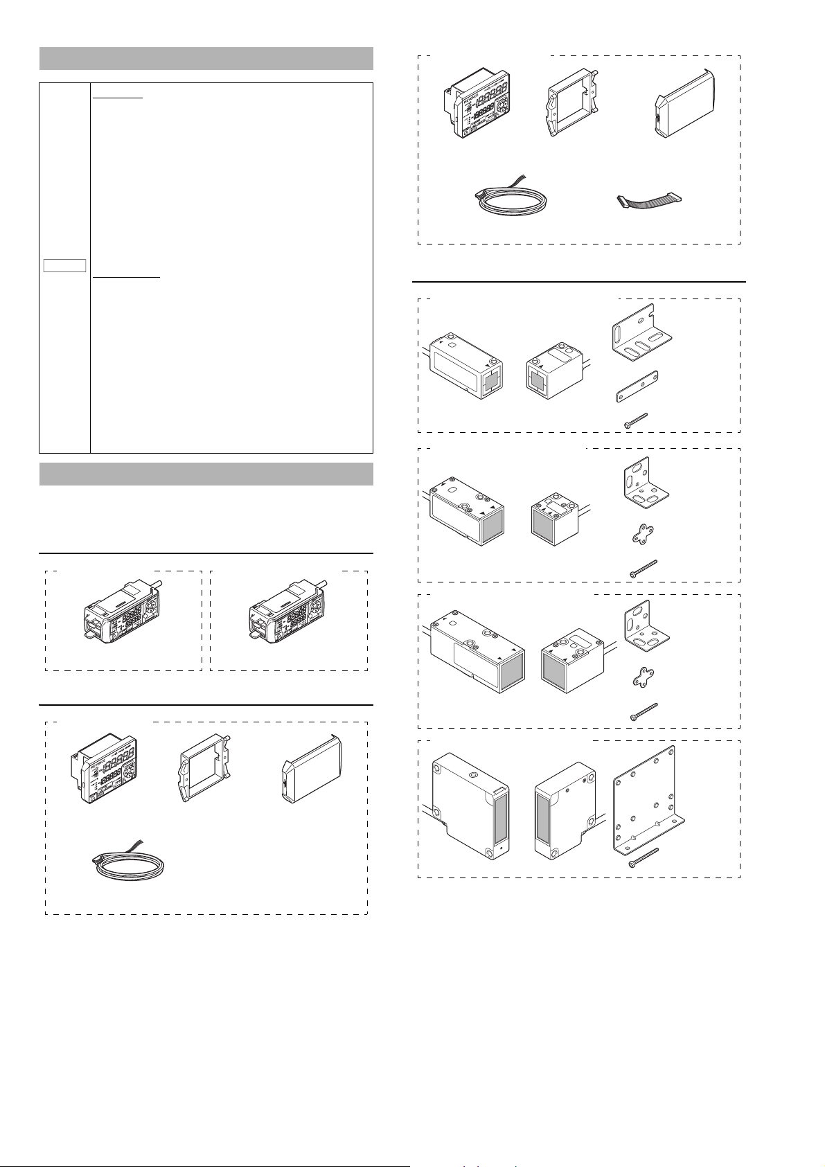
IB-1000 (main unit) IB-1050 (expansion unit)
Amplifier x 1
IB-1500 (main unit)
Panel mounting bracket x 1 Front protection cover x 1
Instruction manual x 1Power/Input-output cable (2 m) x 1
(Number of cable cores: 12)
Amplifier x 1
IB-1550 (expansion unit)
Panel mounting bracket x 1 Front protection cover x 1
Power/Input-output cable (2 m) x 1
(Number of cable cores: 8)
Expansion cable (50 mm) x 1
R
.oN L
A
IRES
R
ESAL
T
IB-01 (Detecting area I1 to 2.5 mm)
Transmitter x 1 Receiver x 1
Mounting bracket x 2
Flat nut x 2
M3 x L20 screw x 4
RE
S
AL
T
R
.oN LA
I
RES
IB-05 (Detecting area 5 mm)
Transmitter x 1 Receiver x 1
Mounting bracket x 2
Flat nut x 2
M3 x L25 screw x 4
RE
S
AL
T
R
.
oN
L
A
I
RES
IB-10 (Detecting area 10 mm)
Transmitter x 1 Receiver x 1
Mounting bracket x 2
Flat nut x 2
M3 x L25 screw x 4
IB-30 (Detecting area 30 mm)
Mounting
bracket x 2
M4 x L25 screw x 6
Transmitter x 1 Receiver x 1
CE Marking
Keyence corporation has confirmed that this product complies
with the essential requirements of the applicable EC Directives,
based on the following specifications. Be sure to consider the
following specifications when using this product in the Member
States of European Union.
EMC Directive
• Applicable standards EMI: EN60947-5-2, Class A
These specifications do not guarantee that the end-product with
this product incorporated complies with the essential
requirements of the EMC Directives. The manufacturer of the
end-product is solely responsible for ensuring the compliance of
the end-product.
Low-voltage Directive
• Applicable standard: EN60825-1
UL Certification
This product is an UL/cUL Listed product.
• UL File No. E301717
• Category: NRKH, NRKH7
Be sure to consider the following specifications when using this
product as an UL/cUL Listed Product.
• Use the power supply with Class 2 output defined in NFPA70
(NEC: National Electrical Code).
• The UL certificate for the IB series is for the sensor head and
amplifier used incombination. The IB series sensor head must
be used together with the IB series sensor amplifier unit
exclusively.
• Power supply/ Control input/ Control output shall be
connected to a single Class 2 source only.
• Use with the over current protection device which is rated 30 V
or more and not more than 1 A.
• Use this product under pollution degree 2.
EMS: EN60947-5-2
Sensor head
z Sensor head
Checking the Package Contents
Before using the unit, confirm that the parts and equipment listed below are
included in the package of the model you purchased.
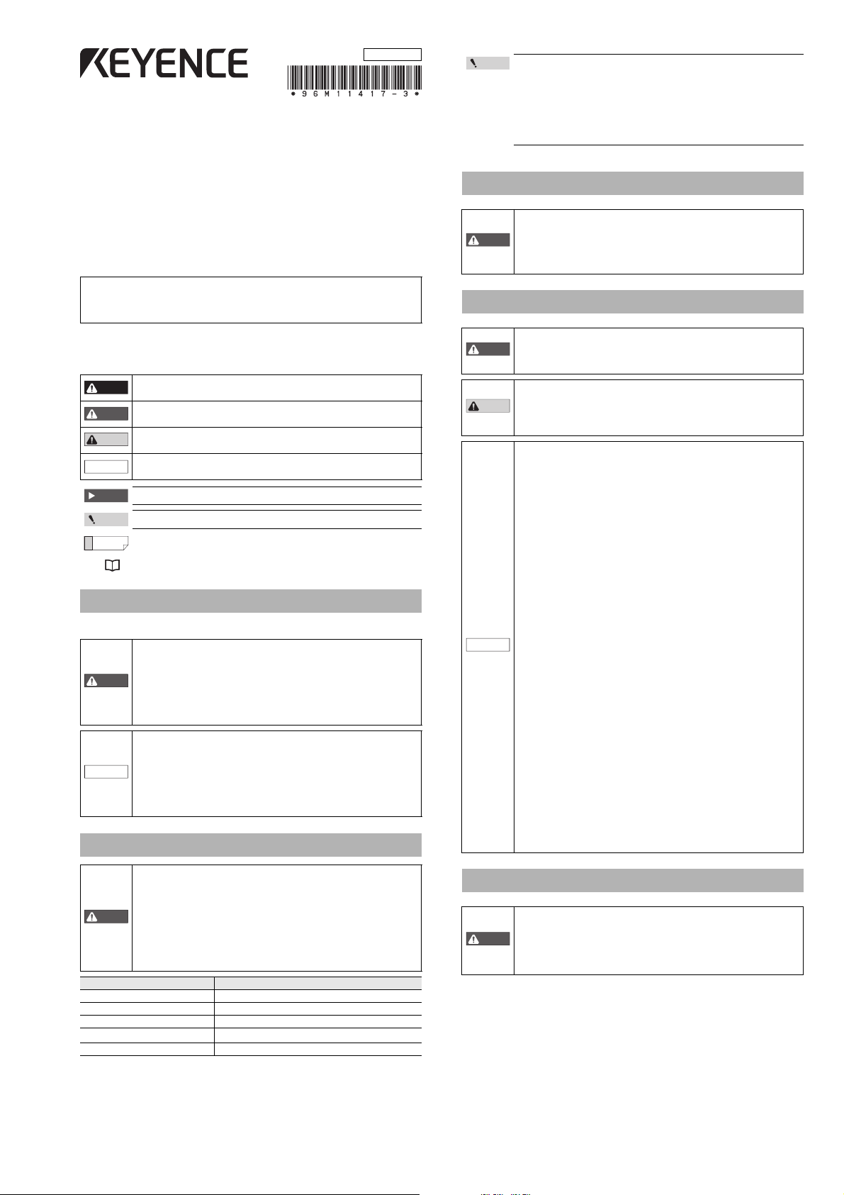
Sensor amplifier unit
z DIN rail mount type
z Panel mount type
LASER
We have thoroughly inspected the package contents before shipment. However, in
the event of defective or broken items, contact your nearest KEYENCE office.
2
Page 3
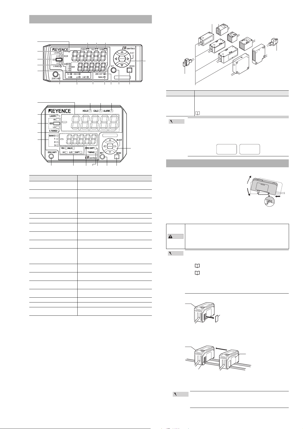
Part Names
IB
(1)
(2)
(3)
(4)
(5)
(6) (7) (8) (9) (10) (11)
(16) (15) (14)
(13
(12)
(1)
(2)
(3)
(4)
(5)
(6) (7) (8) (9) (10) (11) (12)
(16) (15) (14)
(13)
LASER
R
.
o
N LAI
R
ES
RE
S
AL
T
RESAL
T
R
.oN
L
A
IRES
R
.
o
N L
A
IRES
R
ESAL
T
Laser ReceiverLaser transmitter
(1) Laser emission warning indicator
Receiver
Transmitter
Receiver
head
connector
Transmitter
head connector
Point
CAUTION
Point
Connector cover
Main unit
Connecter
Expansion unit
Main unit
Sensor amplifier unit
z DIN rail mount type (IB-1000/IB-1050)
Sensor head
z Panel mount type (IB-1500/IB-1550)
Item Description
(1) Main display
(2) Laser emission warning
indicator
(3) Judgment indicator
(4) Auto adjust indicator Turns on while the auto adjust function is operating.
(5) Bank indicator Indicates the bank in use.
(6) Zero shift button
(7) Sub display identification
indicator
(8) Sub display
(9) Timing input indicator
(10) Zero shift indicator
(11) SET button
(12) MODE button
(13) Arrow buttons
(14) Check indicator Turns on when the check output is on.
(15) Percentage indicator Turns on when the measurement mode is % mode.
(16) Hold indicator
Displays the judgment value (P.V. value) and various
setting items.
Turns on while the laser beam is emitted. Flashes
when laser beam is stopped.
Indicates whether the judgment value (P.V. value) in
respect to the tolerance setting is HIGH (higher than
the upper limit), GO (within tolerance range) or LOW
(lower than the lower limit).
Press this to set the internal measurement value (R.V.
value) to the shift target value.
Turns on according to the type of value displayed on
the sub display.
Displays the internal measurement value (R.V. value),
analog output value and various settings (selections).
If the timing input (external input) is set to level, this
indicator lights while the timing input is on. If the
timing input is set to edge, this indicator turns on for
approx. 0.5 seconds when the timing input is on.
Turns on for approx. 0.5 seconds when zero shift is
executed.
When making various settings, press this button to
automatically set the setting value.
When making various settings, press this button to
start or end the setting or to move the item.
Use this to select the setting item or to change the
details displayed on the sub display.
Turns on when the judgment value (P.V. value) is
held.
Item Description
Always on when the power is supplied to the sensor head. Flashes
(1) Laser emission
warning
indicator
while using the beam axis alignment function. The flashing cycle
quickens as the amount of received light increases and can be uses
as a guide for adjusting the beam axis.
"Beam axis alignment function" (Page 6)
Use a transmitter and receiver with the same serial No.
combination. The operation and accuracy cannot be
guaranteed if units with different serial numbers are used in
combination. The serial No. is attached to the top of the
transmitter and receiver.
SERIAL No.
12345678
Re ceive rTransm itte r
No.
12345678
Mounting the Amplifier
DIN rail mount type, main unit (IB-1000)
Align the claw at the bottom of the main body
with the DIN rail. While pushing the main body in
the direction of the arrow (1), tilt the amplifier in
the direction of the arrow (2).
To remove the amplifier, raise the main body in
the direction of the arrow (3) while pushing it in
the direction of the arrow (1).
(3)
(2)
DIN rail mount type, expansion unit (IB-1050)
Expansion units must be connected to the main unit before they can be used.
Up to 3 expansion units can be connected to one main unit.
• When connecting multiple amplifiers (expansion units), first
check to make sure that the power is turned off to all of the
main and expansion units. Installing an expansion unit with
power on may damage this device.
• Push the amplifiers (expansion units) as far as possible into
the main unit. If they are connected at an angle or not inserted
securely, this device could get damaged.
• When connecting the expansion units, make sure to initialize
the expansion units and set the output polarity.
(1)When turning on the amplifier for the first time after con-
necting the sensor head please reference
"Operation When the Power Is Turned On for the First Time" (Page 6)
(2)When initializing the unit please reference
"Initial Reset (Initialize)" (Page 8)
• Expansion units with different settings for output polarity
(such as an NPN output expansion unit to a PNP output main
unit) cannot be connected together.
• Expansion units using DIN rail mount cannot be connected to
a panel mount style main unit.
1 Remove the expansion protective cover from a IB-1000 (main unit).
(1)
2 Install the amplifiers (expansion units) onto a DIN rail.
Do the same as instructed under "DIN rail mount type, main unit."
3 Push the expansion unit into the main unit connector until a
clicking sound can be heard.
4 Install the end units (OP-26751: 2 units per set) (sold separately)
on both sides of the amplifiers (main or expansion units). Secure
the end units in place with screws on top (2 on each end unit).
The end units are mounted in the same way as the amplifiers.
Mount the amplifiers securely using the end units (OP-26751:
Point
2 units per set) (sold separately) or a commercially available
DIN rail mounting tool to prevent the amplifiers from slipping
and coming off from the DIN rail due to machine vibration.
3
Page 4
Panel mount type, main unit (IB-1500)
· Panel thicknes 1 to 6 mm
· X = 48 × (Number of amplifiers) - 3
+ 0.6
- 0
45 mm
+ 0.6
- 0
45 mm
+ 0.6
- 0
45 mm
X mm
Minimum 85 mm
When stacking
the units vertically.
When stacking
the units horizontally.
Panel mounting bracket
Panel
Amplifier
Front protection cover
CAUTION
Point
Expansion
cable
Point
Unlocked
Lock cover
Click
DIN rail mount type
(IB-1000/IB-1050)
Panel mount type
(IB-1500/IB-1550)
Blue O-ring
Right side is R side
Bottom is R side
Locked
Lock cover
1 Make a hole on the panel as shown in the diagrams below.
2 Insert the back side of amplifier to the hole of the panel.
3 Arrange the panel mounting bracket in the direction below,
mount to the amplifier from the back and attach the front
protection cover to the amplifier.
To remove the panel mounting bracket, widen
the claws at both ends of the panel mounting
tool using a screwdriver, as demonstrated in the
image on the right.
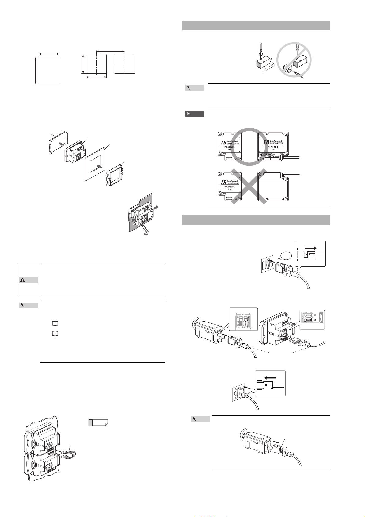
Mounting the Sensor Head
Mounting the sensor head
Mount the sensor head with
the enclosed screws (IB-01/
IB-05/IB-10: M3, IB-30: M4).
Tightening torque: 0.3 N
less
(Tightening torque for IB-01:
0.1N
·m or less)
Important
·m or
• Always use mounting holes facing the same direction for
the sensor head transmitter and receiver. (Excluding IB-01)
• Do not tighten the screws with a torque exceeding 0.3 N.m.
The sensor head could deform, thus preventing beam axis
alignment.
When mounting the sensor, confirm that the transmitter and
receiver faces on which the nameplate label is attached are
facing the same direction. (Only for IB-30)
Panel mount type, expansion unit (IB-1550)
Expansion units must be connected to the main unit before they can be used.
Up to 3 expansion units can be connected to one main unit.
• When connecting the expansion cable, make sure to turn off
the power beforehand. Inserting or removing the cable with
the power turned on may cause damage to the units.
• Push the expansion cable connector securely all the way. Take
care not to insert the connector at an angle and to insert it
securely or the units could get damaged.
• When connecting the expansion units, make sure to initialize
the connected expansion units and set the output polarity.
(1)
When turning on the amplifier for the first time after connecting the sensor head please reference
"Operation When the Power Is Turned On for the First Time" (Page 6)
(2)
When initializing the unit please reference
"Initial Reset (Initialize)" (Page 8)
• Expansion units with different settings for output polarity
(such as an NPN output expansion unit to a PNP output main
unit) cannot be connected together.
• Expansion units using panel mount cannot be connected to a
DIN rail mounted main unit.
1 Make the appropriate number of holes in the panel according to
the number of amplifiers required (expansion units).
For the panel cutting measurement, refer to the "Panel mount type, main unit".
2 Install the amplifiers (expansion units) on the panel.
For the amplifier mounting method, refer to the "Panel mount type, main unit".
3 Connect the amplifiers (main and expansion units) using the
expansion cable (50 mm) supplied with the expansion unit.
When arranging the amplifiers
Reference
side by side, the 300 mm
expansion cable (OP-35361)
is required.
Connection and Wiring
Connecting the sensor head and amplifier
1 Attach the receiver's sensor
head connection cable to the
amplifier’s [R] connector.
Remove the lock cover of the
connector and insert it into the
connectors of amplifier until a
clicking sound can be head.
2 Attach the lock cover to the connector to secure the cable.
When removing the sensor head connection cable, push the
Point
lock lever and pull it back.
Lock lever
4
Page 5

3 Attach the transmitter’s sensor head connection cable to the
Top is T side
Red O-ring
Left is T side
Brown
Black
White
Blue
Power/Input-output cable
To attach To remove
Brown
Blue
Black
White
Gray
Light blue
Orange
Shield
Pink
Yellow
Pink/Purple
Purple
Green
10 to 30 VDC
0 V
HIGH judgment output
LOW judgment output
GO judgment output
Analog output +
Analog output GND
External input 1
(Zero shift input)
External input 2 (Reset input)
External input 3 (Timing input)
External input 4 (Not Used)
Check output
*1 *4
*1
*1
*2
*2
*3
*3
*3
*3
LASER
BANK
0
1
2
3
HI
GO
LO
R.V.
ANALOG
HI SHIFT
ZERO SHIFT
TIMING
LO
ALIGNMENT
HOLD CALC
CHECK
Press [MODE] and [SET]
for 2 seconds
for 2 seconds
Press [MODE]
press [SET] for 5 times
While pressing [MODE]
press for 2 seconds
or
While pressing [MODE]
for 2 seconds
Press and
Press [MODE] and
for 2 seconds
[MODE] and , or [MODE] and
Press and
[HOLD] ON
amplifier’s [T] connector.
DIN rail mount type
(IB-1000/IB-1050)
Panel mount type
(IB-1500/IB-1550)
z Power/Input-output cable
The following information shows the details of power/Input-output cable. For
information about the input-output circuit, see page 10 of this Instruction Manual.
The connection procedures are the same as the receiver side.
Attaching the sensor head cable connector
(OP-87060: optional)
Cut the sensor head cable to the required length and attach the new connector to
use the sensor. The connection method is the same for the transmitter and receiver.
1 Cut the cable to the required length and strip approx. 15 mm of
insulation from the end.
Point
Do not strip the core wire insulation.
2 Insert each color coded cable into the same colored marked
points on the connector.
Each cable is secured temporarily when it is inserted completely.
3 Confirm that all the cables are inserted properly into the
connector and crimp them using pliers or a similar tool.
Once the connector has been installed, make sure to connect
Point
it to the amplifier and confirm that the sensor operates
normally.
If the sensor head does not function properly, crimp the
connector again using pliers or a similar tool.
Once the connector is crimped, it cannot be reused.
Amplifier wiring
z Connecting power/Input-output cable (IB-1500/IB-1550 panel
mount type)
Connect the power/Input-output cable to the panel mount type main unit and
Input-output cable to the expansion units.
• The number of core wires for the power/Input-output cable
Point
for the main unit is 12, and the number of core wires for
the Input-output cable for the expansion units is 8.
• Power for the expansion units is supplied from the main
unit.
• When not using the I/Os of expansion units, cut the cable
near the connector.
Insert further
than here.
*1 IB-1050/IB-1550 (expansion unit) do not have brown, blue, or light blue wires.
Power is supplied to the expansion units through the IB-1000/IB-1500 (main unit).
*2 The Analog output can be set for the following: Not used (OFF), 0 to 5 V, r5 V, 1
to 5 V and 4 to 20 mA.
"Operation When the Power Is Turned On for the First Time" (Page 6)
"Initial Reset (Initialize)" (Page 8).
*3 In addition to the selections noted on the image above, the external inputs can
also be selected to perform the following: Bank A input, Bank B input, Laser
emission stop input and Not used (OFF).
Amplifier Functions and Displays
Setting method
Main screen
"Reference Light Registration (Gain
Adjustment)" (Page 7)
"Setting procedures (Basic)" (Page 8)
"Initial Reset (Initialize)" (Page 8)
"Adjust function" of the IB Series User's
Manual
"Switching the bank with button
operations" of the IB Series User's
Manual
"4-3 Calibration Function" of the IB
Series User's Manual
"3-9 Key Lock Function" of the IB Series
User's Manual
"Beam axis alignment function"
(Page 6)
Main screen
z P.V. (judgment value) and R.V. (internal measurement value)
R.V. value (internal measurement value) is the measurement value displayed on the
sensor amplifier.
* R.V. = Raw Value
P.V. (judgment value) is the value used for setting the judgment output to ON or OFF
based on the tolerance setting value. Also, the analog output is based on the P.V.
value.
* P.V. = Present Value
"Setting the Tolerance Setting Value" (Page 7)
The P.V. (judgment value) and R.V. (internal measurement value) are basically the
same, however, those values differ when the hold function is used.
z Main display (Upper level)
P.V. (judgment value) is displayed on the main display. Normally, the display differs
as shown below when using the hold function.
5
Normal
The same value as the R.V. (internal measurement value) is
displayed.
When the hold function is being used
The P.V. value (judgment value) is held following the hold function
settings.
For details, refer to the IB Series User's Manual.
Page 6

z Sub display (Lower level)
S/T
LASER
BANK
0
1
2
3
HI
LO
R.V.
ANALOG
HI SHIFT
ZERO SHIFT
TIMING
LO
ALIGNMENT
HOLD CALC
CHECK
GO
GO
HOLD CALC
CHECK
X
LASER
BANK
0
1
2
3
HI
LO
R.V.
ANALOG
HI SHIFT
ZERO SHIFT
TIMING
LO
ALIGNMENT
GO
LASER
BANK
0
1
2
3
HI
LO
R.V.
ANALOG
HI SHIFT
ZERO SHIFT
TIMING
LO
ALIGNMENT
HOLD CALC
CHECK
GO
HOLD CALC
CHECK
LASER
BANK
0
1
2
3
HI
LO
R.V.
ANALOG
HI SHIFT
ZERO SHIFT
TIMING
LO
ALIGNMENT
GO
HOLD CALC
CHECK
LASER
BANK
0
1
2
3
HI
LO
R.V.
ANALOG
HI
SHIFT
ZERO SHIFT
TIMING
LO
ALIGNMENT
R.V.
[R.V.]
ON
Analog output
[ANALOG]
ON
HIGH setting value
[HI]
ON
LOW setting value
[LO]
ON
Shift target value
[SHIFT]
ON
QHH
#P.)
Analog output
Reference
1
LASER
BANK
0
1
2
3
HI
LO
R.V.
ANALOG
HI SHIFT
ZERO SHIFT
TIMING
LO
ALIGNMENT
#.K)P
GO
HOLD CALC
CHECK
Received light
Transmitter
ReceiverReceiver
1
LASER
BANK
0
1
2
3
HI
LO
R.V.
ANALOG
HI SHIFT
ZERO SHIFT
TIMING
LO
ALIGNMENT
#.K)P
GO
HOLD CALC
CHECK
Beam axis is misaligned.
Transmitter
1
LASER
BANK
0
1
2
3
HI
LO
R.V.
ANALOG
HI SHIFT
ZERO SHIFT
TIMING
LO
ALIGNMENT
#.K)P
GO
HOLD CALC
CHECK
Beam axis is aligned.
Off
Blink (slow)
Blink (fast)
The sub display switches with each push of the W or X button. According to the
type of displayed value selected, the sub display identification indicator will show
one of the following: [R.V. / ANALOG / HI / LO / SHIFT]
R.V. (internal measurement value)
The R.V. (internal measurement value) is displayed. This
displayed value is not held.
Adjusting the Beam Axis
Adjust the laser beam’s axis.
1 Fix the receiver so that the transmitter and receiver are on the
same line.
2 With no object set in the detection area, move the transmitter
and fix it where the display value is the largest.
Transmitter
Analog output (The analog output will only be displayed for
the main unit and only when it is enabled.)
The voltage value (unit: V) or current value (unit: mA) of the
analog output is displayed.
"Operation When the Power Is Turned On for the First Time" (Page 6)
"Initial Reset (Initialize)" (Page 8)
HIGH setting value
The upper limit of the acceptable range (tolerance setting
value) for the object that is being measured is displayed.
Also, the setting value can be changed. If the P.V. (judgment
value) exceeds the value set here, the HIGH output signal
will be sent.
"Setting the Tolerance Setting Value" (Page 7)
LOW setting value
The lower limit of the acceptable range (tolerance setting
value) for the object that is being measured is displayed.
Also, the setting value can be changed. If the P.V. (judgment
value) falls below the value set here, the LOW output signal
will be sent.
"Setting the Tolerance Setting Value" (Page 7)
Shift target value
When the zero shift button is pressed or the zero shift input is
set to ON, the R.V. (internal measurement value) will be
matched to the value set here.
"Zero Shift Function (Shifting the Internal Measurement
Value)" (Page 7)
Operation When the Power Is Turned On for the First Time
When the amplifier is turned on for the first time after the sensor head is connected,
the initial setting display appears. Make the initial setting according to the following
procedure as this is necessary for both the main unit and the expansion units when
units are added.
1 Select the judgment output and check output
polarity with the S/T button, and press the
[MODE] button.
Setting value Description
PRP NPN output
RPR PNP output
2 Press the
output method and press the [MODE] button.
Setting value Description
QHH Not output
W
W
W
C/RT
After the setting is complete, [GPF] blinks several times on the sub display and
changes to the main screen.
3 Carry out “Adjusting the beam axis” (page 6) and
Make other settings as necessary.
button to select the analog
Analog output after the judgment value is
converted to the range from 0 to 5 V.
"Reference Light Registration (Gain Adjustment)" (Page 7).
Analog output after the judgment value is
converted to ±5 V.
Analog output after the judgment value is
converted to the range from 1 to 5 V.
Analog output after the judgment value is
converted to the range from 4 to 20 mA.
Once the initial setting is completed, the initial setting display
Point
will not appear when the power is turned on the second time or
the after. To change the initial setting, perform the initial reset.
"Initial Reset (Initialize)" (Page 8)
QWV
PRP
Output polarity
Receiver
The beam axis does not need to be adjusted if the base of the
sensor head and the left side of the receiver looking from the
transmitter are installed on the same reference surface.
Beam axis alignment function
The IB series has a beam axis alignment function which makes it easy to adjust the
beam axis.
The beam axis can be adjusted easily with the help of the amplifier unit's display
and sensor head laser emission warning indicator.
1 Press the W/X buttons on the main screen simultaneously for 2
seconds, and display the received light on the sub display (lower
level).
2 With no object in the detection area, move the transmitter and
mount the transmitter and receiver so that the displayed
received light is the largest.
When the beam axis is aligned, the value on
the sub display (lower level) will increase. Fix
the units where the value is the largest when
possible.
At this time, the laser emission warning
indicator on the sensor head will turn off or
blink. The indicator's flashing cycle quickens
as the received light increases.
Adjust the beam axis together with the
incoming light level on the sub display (lower
level).
T
AL
S
Laser emission warning indicator
Laser emission
warning indicator
Off
Blink (slow)*
Blink (fast)*
* The blinking cycle changes in stages. The faster the indicator blinks, the more
accurate the beam axis alignment is.
Description Status drawing
State when laser beam is
not transmitted into receiver.
Axis beam is misaligned.
Axis beam is approximately
aligned.
R
.oN L
AI
RE
S
R
.
oN
L
E
R
AIRES
.
oN
LA
I
R
RE
T
L
A
S
E
R
T
AL
S
RE
S
LASER
3 The main screen will reappear when a random button on the
amplifier unit is pressed.
Reference
All judgment outputs turn off while using the beam axis
alignment function. The analog voltage output is fixed to 5.5 V
and the analog current output is fixed to 3.0 mA.
6
Page 7

W/X
S/T
S/T
W/X
S/T
Reference Light Registration
Point
LASER
BANK
0
1
2
3
HI
LO
R.V.
ANALOG
HI SHIFT
ZERO SHIFT
TIMING
LO
ALIGNMENT
HOLD CALC
CHECK
GO
R.V. value
[
R.V.
]
ON
Tolerance tuning setting width
Measurement upper limit
HIGH side setting value (upper limit)
Master workpiece P.V.
(judgment value)
LOW side setting value (lower limit)
Measurement lower limit
Point
[LO]
ON
LOW setting value
Measurement value of
HIGH limit defective target
Measurement value of
LOW limit defective target
Measurement value of acceptable target
Measurement upper limit
Measurement lower limit
LOW setting value(lower limit )
HIGH setting value(upper limit)
Point
HIGH setting value
[HI]
ON
[LO]
ON
LOW setting value
(Gain Adjustment)
The amount of received light when the sensor head is mounted for the first time is
registered as the reference light amount.
Perform “reference light registration (gain adjustment)” when using the sensor for
the first time or each time the sensor head mounting position has been changed,
etc.
1 Adjust the beam axis.
2 Press the [MODE] and [SET] buttons on the main screen
simultaneously for 2 seconds.
[#.K)P] will display on the main display (upper level), and the reference light
amount will be registered. The main screen will reappear when the registration
is completed.
• Reference light registration (gain adjustment) cannot be
carried out with external inputs. It must be carried out
with the buttons on the main unit.
• If reference light registration (gain adjustment) is
attempted when the received light is low, an error will
appear and the registration will be canceled.
"Displayed Contents and Corrective Actions" (Page 9)
Setting the Tolerance Setting Value
There are two types of tolerance setting values: HIGH (upper limit) and LOW (lower
limit). The value displayed will output its signal as one of the following 3 levels:
When the value exceeds the upper limit (HIGH); when the value is within the
tolerance range (GO); and when the value falls below the lower limit (LOW).
"4. Output mode [QWV]" (Page 8)
Automatic setting (Tolerance tuning)
When a reference workpiece (master workpiece) is available, HIGH tolerance value
(upper limit) and LOW tolerance value (lower limit) can be automatically set
symmetrically with respect to the measured value of the master workpiece.
1 Press the W/X button several times on the
main screen. Display the R.V. (internal
measurement value) on the sub display (lower
level). ([R.V.] will turn on.)
2 Measure the master workpiece, and then press the [SET] button.
The P.V. (judgment value) is imported as the tolerance setting reference value.
[5GV] and the tolerance setting value will alternately display on the sub display
(lower level).
3 Set the tolerance width with the S/T button,
and then press the [SET] button.
Measurement mode Setting range Default value
% mode 0.00 to 999.99 10.00
Dimension mode 0.000 to 99.999 1.000
Master workpiece P.V. value
HOLD CALC
0
1
2
3
ANALOG
R.V.
HI SHIFT
LO
ZERO SHIFT
CHECK
TIMING
LASER
HI
GO
LO
BANK
ALIGNMENT
Setting width of tolerance value
4 Press the X button once, and display the LOW
setting value on the sub display (lower level).
5 Measure the acceptable target again, and press
the [SET] button.
The R.V. (internal measurement value) will be imported.
[.Q5GV] will appear on the main display (upper level).
6 Measure a LOW limit defective target, and press the [SET] button.
The R.V. (internal measurement value) will be imported.
After [5GV] blinks on the main display (upper level), the P.V. (judgment value) will
appear.
The middle value between the measurement value of the acceptable target
measured in Step 5 and the measurement value of the LOW limit defective
target will appear on the sub display (lower level).
This completes setting the LOW setting value (upper limit), and completes
2-point tuning.
Two-point tuning cannot be performed if the internal
measurement value (R.V.) is [], [((((] or [((((]. If
performed, [PQW#.] will blink several times on the main
display.
Manual setting
Set the HIGH setting value (upper limit) and LOW setting value (lower limit) to an
arbitrary value.
1 Press the
main screen. Then display the HIGH setting
value on the sub display (lower level).
2 Press
value.
3
Press the X button once and display the LOW
setting value on the sub display (lower level).
4 Press the
value.
The tolerance settings are complete.
button several times on the
button to set the HIGH setting
Measurement mode Setting range Default value
% mode – 999.99 to 999.99 20.00
Dimension mode – 99.999 to 99.999 2.000
button to set the LOW setting
Measurement mode Setting range Default value
% mode – 999.99 to 999.99 10.00
Dimension mode – 99.999 to 99.999 1.000
When setting the tolerance value with the 2-point tuning or manually,
Point
make sure to set "HIGH tolerance value > LOW tolerance value".
4 Press the [SET] button to complete the tolerance tuning.
[5GV] blinks on the main display (upper level), and the HIGH setting value and
LOW setting value are determined. Then, the display returns to the R.V. screen
automatically.
Automatic setting (2-point tuning)
If there are an acceptable target and a HIGH or LOW limit defective target, the
middle value between the acceptable and the HIGH or LOW limits can be set as the
tolerance value.
1 Press the W/X button several times on the
main screen. Display the HIGH setting value on
the sub display (lower level). ([R.V.] will turn
on.)
2 Measure an acceptable target, and press the [SET] button.
The R.V. (internal measurement value) will be imported.
[*K5'V] will appear on the main display (upper level).
3 Measure a HIGH limit defective target, and press the [SET]
button.
The R.V. (internal measurement value) will be imported.
After [5'V] blinks on the main display (upper level), the P.V. (judgment value) will
appear.
The middle value between the measurement value of the acceptable target
measured in Step 2 and the measurement value of the HIGH limit defective
target will appear on the sub display (lower level).
This completes setting the HIGH setting value (upper limit).
Tolerance tuning cannot be performed when the displayed
P.V. (judgment value) is [], [((((] or [((((]. [PQW#.]
will blink several times on the main display if attempted.
HIGH setting value
[HI]
ON
Zero Shift Function (Shifting the Internal Measurement Value)
When the [ZERO SHIFT] button is pressed or the external zero shift input* has been
activated, the R.V. (internal measurement value) now becomes the newly shifted
target value.
* Zero shift via external input is provided by assigning zero shift input to the
external input 1 (pink wire).
Setting the shift target value
1 Use the
2 Press the
Performing the zero shift
Press the [ZERO SHIFT] button or assign zero shift input to an external input.
The zero shift indicator [ZERO SHIFT] will light up for approx. 0.5 seconds and the
current R.V. (internal measurement value) will now become the shifted target value.
Cancelling the zero shift
Press the zero shift button [ZERO SHIFT] for 2 seconds or more.
The sub display shows [T'5'V], indicating that the zero shift has been cancelled
and set back to the factory setting.
7
button on the main screen to display the shift target
value on the sub display (lower level).
button to change the shift target value.
Measurement mode Setting range Default value
% mode – 999.99 to 999.99 0.00
Dimension mode – 99.999 to 99.999 0.000
The shift target value has now been set.
When using the external zero shift function, any newly shifted
Point
states will be lost when the unit is powered down unless the
status save function is utilized.
For details, refer to the IB Series User's Manual.
Page 8

S/T
[GU
S/T
S/T
(0E
.F
#X'
QWV
Initial Reset (Initialize)
;GU
T'5'V
Performing the initial re set
QHH
#P.)
Analog output
Reference
.K)JV
.F
PQ
QWV
.K)J6 F#T-
2EV .'P 2E V .'P
Normally open [PQ]
Judgment
Judgment output
HIGH GO LOW
HIGH ON OFF OFF
GO OFF ON OFF
LOW OFF OFF ON
Error ON OFF ON
[] OFF OFF OFF
Normally closed [PE]
Judgment
Judgment output
HIGH GO LOW
HIGH OFF ON ON
GO ON OFF ON
LOW ON ON OFF
Error OFF ON OFF
[] ONONON
The initial reset initializes all settings except for the calibration setting.
The initial reset can also be used to change the judgment output and analog output
settings.
1 While holding down the [MODE] button on the main screen,
press the [SET] button 5 times.
[TGUGV] will be displayed on the main display.
2 Press
3 Press
4 Press the
z Calling the setting display
Hold the [MODE] button for approx. 2 seconds on the main screen.
The setting display appears.
Basic operations on the setting display
To change the setting, press the S/T button
To move the next item, press the [MODE] button or X button
To return to the previous item, press the W button
To skip the rest of the settings and finish, press and hold the [MODE] button for
approx. 2 seconds
Setting procedures (Basic)
[MODE] button.
If [PQ] is selected, the settings of output polarity and
analog output can be changed without initial reset.
button to select the output polarity
and press the [MODE] button.
Setting value Description
PRP NPN output
RPR PNP output
button to select the analog
button to select [
] and press the
QWV
Output polarity
output and press [MODE] button.
Setting value Description
QHH Not using the analog output
W Analog output range is from 0 to 5 V.
W Analog output range is ±5 V.
W Analog output range is from 1 to 5 V.
C/RT Analog output range is from 4 to 20 mA.
After the initialization is complete, [GPF] blinks several times on the sub display
and the main screen is restored.
If any button other than the S/T button and [MODE] button are
pressed halfway through the initial reset procedure, the initial
reset is stopped and returned to the screen displayed in step 2.
Setting Method
Press the [MODE] button for 2 seconds.
(PE
2EV
Press the [MODE] or X button.
Press the [MODE] or X button.
#W'
Main screen
"1. Measurement
mode"
"2. Received/
Blocked light
mode"
"3. Averaging/
High-pass filter"
Use S/T to select.
The % mode and dimension mode are set.
Use S/T to select.
The received light mode and blocked light
mode are set.
Use S/T to select.
Set the number of averages. When HPF is
selected, set the high-pass filter.
PRP
Basic setting
1. Measurement mode [
Select whether to display the received light (or blocked light) of the laser beam
emitted to the receiver as a dimension (mm) or a percentage (%) in respect to the
measurement range.
Setting value Description Default value
2EV
.'P Display as a dimension (mm).
Display as a percentage (%) in respect to the
measurement range.
2. Received/Blocked light mode [
Select whether to display according to the light transmitted into the receiver or
according to the amount of light blocked.
Setting value Description Default value
.K)J6
&#T-
Reference
Totally unblocked
Partially blocked
Totally blocked
Display according to the amount of laser beam
transmitted into the receiver.
Display according to the blocked light (amount of
shadow).
Each sensor head’s measurement status and R.V. (internal
measurement value) when set to the "1. Measurement mode" and "2.
Received/Blocked light mode" are as follow.
Received/Blocked
Measurement mode
IB-01 100.00 1.000 0.00 0.000
IB-05 100.00 5.000 0.00 0.000
IB-10 100.00 10.000 0.00 0.000
IB-30 100.00 30.00 0.00 0.00
IB-01 50.00 0.500 50.00 0.500
IB-05 50.00 2.500 50.00 2.500
IB-10 50.00 5.000 50.00 5.000
IB-30 50.00 15.00 50.00 15.00
IB-01 0.00 0.000 100.00 1.000
IB-05 0.00 0.000 100.00 5.000
IB-10 0.00 0.000 100.00 10.000
IB-30 0.00 0.00 100.00 30.00
3. Averaging/High-pass filter [
z Averaging
The average value is moved and averaged. If the measured values fluctuate, stable
measurements can be obtained by increasing the average number of times. When
[*2(] is set, the high-pass filter will be enabled.
Item Setting range Default value
Averaging //////////*2(
z High-pass filter
This function ignores fluctuations which are less than an arbitrary frequency (cut-off
frequency), and displays the results. This is effective to ignore gradual changes
and only capture the sudden changes. When [*2(] is selected on the averaging
setting screen, the cut-off frequency setting screen will open.
Item Setting range Default value
Cut-off frequency /////// //
Reference
The following process takes place when the high-pass filter is set.
Measured
value
Input waveform
light mode
]
]
.
]
Measured
value
Waveform onto
which high-pass
filter was applied
c
c
Press the [MODE] or X button.
Press the [MODE] or X button.
'PF
Press the T or S button.
2TQ
Press the [MODE] or X button.
Advanced setting
"4. Output mode"
"Basic setting
complete"
"Advanced settings"
Use S/T to select.
Set N.O. (Normally Open) or “N.C.
(Normally Closed).
Press the [MODE] button or X button to
return to the main screen.
IB Series User's Manual
Press the W button to return to the main screen.
When Advanced Settings is selected, the
following items can be set. Refer to the IB Series
User’s Manual for details.
“5. Hold function”, “6. Timing input”, “7. Delay
timer”, “8. Hysteresis”, “9. Analog output
scaling”, “10. External input”, “11. Bank
switching method”, “12. Save zero-shift state”,
“13. Save adjust state”, “14. Adjust level”, “15.
Auto adjust function", “16. Check output
function”, “17. Error output mode”, “18. Display
digit”, “19. Power save function”, “20. Judgment
indicator color”, “21. P.V. value display color”
Time
4. Output mode [
Setting the judgment output method
Setting value Description Default value
PQ Output is normally open. c
PE Output is normally closed.
Reference
]
8
Time
Page 9

Displayed Contents and Corrective Actions
Reference
VT
LASER
BANK
0
1
2
3
HI
LO
R.V.
ANALOG
HI SHIFT
ZERO SHIFT
TIMING
LO
ALIGNMENT
'T*
GO
HOLD CALC
CHECK
TV
LASER
BANK
0
1
2
3
HI
LO
R.V.
ANALOG
HI SHIFT
ZERO SHIFT
TIMING
LO
ALIGNMENT
'T*
GO
HOLD CALC
CHECK
Alternate display
T
LASER
BANK
0
1
2
3
HI
LO
R.V.
ANALOG
HI SHIFT
ZERO SHIFT
TIMING
LO
ALIGNMENT
'T*
GO
HOLD CALC
CHECK
.#5'4
LASER
BANK
0
1
2
3
HI
LO
R.V.
ANALOG
HI SHIFT
ZERO SHIFT
TIMING
LO
ALIGNMENT
'T*
GO
HOLD CALC
CHECK
V
LASER
BANK
0
1
2
3
HI
LO
R.V.
ANALOG
HI SHIFT
ZERO SHIFT
TIMING
LO
ALIGNMENT
'T*
GO
HOLD CALC
CHECK
T#P)G
LASER
BANK
0
1
2
3
HI
LO
R.V.
ANALOG
HI SHIFT
ZERO SHIFT
TIMING
LO
ALIGNMENT
'T*
GO
HOLD CALC
CHECK
VK06
LASER
BANK
0
1
2
3
HI
LO
R.V.
ANALOG
HI SHIFT
ZERO SHIFT
TIMING
LO
ALIGNMENT
'T*
GO
HOLD CALC
CHECK
LASER
BANK
0
1
2
3
HI
LO
R.V.
ANALOG
HI SHIFT
ZERO SHIFT
TIMING
LO
ALIGNMENT
'T%
GO
HOLD CALC
CHECK
LASER
BANK
0
1
2
3
HI
LO
R.V.
ANALOG
HI SHIFT
ZERO SHIFT
TIMING
LO
ALIGNMENT
'T'
GO
HOLD CALC
CHECK
Reference
-
LASER
BANK
0
1
2
3
HI
GO
LO
R.V.
ANALOG
HI SHIFT
ZERO SHIFT
TIMING
LO
ALIGNMENT
'4)
HOLD CALC
CHECK
KP(
LASER
BANK
0
1
2
3
HI
GO
LO
R.V.
ANALOG
HI SHIFT
ZERO SHIFT
TIMING
LO
ALIGNMENT
'4)
HOLD CALC
CHECK
-
LASER
BANK
0
1
2
3
HI
GO
LO
R.V.
ANALOG
HI SHIFT
ZERO SHIFT
TIMING
LO
ALIGNMENT
'4#&,
HOLD CALC
CHECK
QW'T
LASER
BANK
0
1
2
3
HI
GO
LO
R.V.
ANALOG
HI SHIFT
ZERO SHIFT
TIMING
LO
ALIGNMENT
'4#&,
HOLD CALC
CHECK
LASER
BANK
0
1
2
3
HI
GO
LO
R.V.
ANALOG
HI SHIFT
ZERO SHIFT
TIMING
LO
ALIGNMENT
'4EQ/
HOLD CALC
CHECK
LASER
BANK
0
1
2
3
HI
LO
R.V.
ANALOG
HI SHIFT
ZERO SHIFT
TIMING
LO
ALIGNMENT
HOLD CALC
CHECK
GO
LASER
BANK
0
1
2
3
HI
LO
R.V.
ANALOG
HI SHIFT
ZERO SHIFT
TIMING
LO
ALIGNMENT
HOLD CALC
CHECK
GO
((((
LASER
BANK
0
1
2
3
HI
LO
R.V.
ANALOG
HI SHIFT
ZERO SHIFT
TIMING
LO
ALIGNMENT
((((
HOLD CALC
CHECK
GO
((((
LASER
BANK
0
1
2
3
HI
LO
R.V.
ANALOG
HI SHIFT
ZERO SHIFT
TIMING
LO
ALIGNMENT
((((
HOLD CALC
CHECK
GO
LASER
BANK
0
1
2
3
HI
LO
R.V.
ANALOG
HI SHIFT
ZERO SHIFT
TIMING
LO
ALIGNMENT
.QE
GO
HOLD CALC
CHECK
LASER
BANK
0
1
2
3
HI
LO
R.V.
ANALOG
HI SHIFT
ZERO SHIFT
TIMING
LO
ALIGNMENT
PQW#.
GO
HOLD CALC
CHECK
'TT
LASER
BANK
0
1
2
3
HI
LO
R.V.
ANALOG
HI SHIFT
ZERO SHIFT
TIMING
LO
ALIGNMENT
5JK(6
GO
HOLD CALC
CHECK
'TT
LASER
BANK
0
1
2
3
HI
LO
R.V.
ANALOG
HI SHIFT
ZERO SHIFT
TIMING
LO
ALIGNMENT
5'6
GO
HOLD CALC
CHECK
LASER
BANK
0
1
2
3
HI
LO
R.V.
ANALOG
HI SHIFT
ZERO SHIFT
TIMING
LO
ALIGNMENT
E/.QE
GO
HOLD CALC
CHECK
When an error is displayed, the judgment output changes to the error state.
"4. Output mode [QWV]" (Page 8)
• The check output functions regardless of the error judgment.
• When [GT% ] is displayed, all the judgment outputs and check
outputs will turn OFF.
• When an error other than ['T%] or ['T'] is displayed, the analog
voltage output is 5.5 V and the analog output current is 3.0 mA.
Error indication Error contents Remedy
Head error
Transmitter/receiver
reverse connection
error
Receiver error
Transmitter laser
error
Transmitter error
Model mismatch
error
The transmitter or receiver is not
connected to the amplifier unit.
The sensor head cable is not
connected correctly.
The transmitter or receiver is defective.
The sensor head cable for the
transmitter or receiver is broken.
The transmitter and receiver are
connected to the amplifier unit in
revers e.
The receiver is not connected to the
sensor amplifier.
The sensor head cable connector is
not connected correctly.
The receiver is broken.
The sensor head cable for the receiver
is broken.
The laser in the transmitter is broken.
The transmitter is not connected to the
sensor amplifier.
The sensor head cable connector is
not connected correctly.
The transmitter is broken.
The sensor head cable for the
transmitter is broken.
The transmitter and receiver model
(measurement range) do not match.
Correctly connect the
transmitter and receiver.
Connect the connector
again.
Replace the transmitter
or receiver.
Replace the sensor head
cable.
Correctly connect the
transmitter and receiver.
Correctly connect the
receiver.
Connect the connector
again.
Replace the transmitter
or receiver.
Replace the sensor head
cable.
Replace the transmitter
or receiver.
Correctly connect the
transmitter.
Connect the connector
again.
Replace the transmitter
or receiver.
Replace the sensor head
cable.
Use a transmitter and
receiver from the same
model (measurement
range).
Error indication Error contents Remedy
• Perform reference light
registration (gain
adjustment).
• Adjust the beam axis.
• Clean the laser
transmitter and
receiver sections on
the sensor head.
• Increase the adjust
level.
• Perform reference light
registration (gain
adjustment).
• Increase the adjust
level.
• Make sure that the
interfering light does
not enter the laser
receiver.
• Connect the transmitter
and receiver in
combination to the
same amplifier unit.
Turn the power OFF and
check the connections
between the amplifiers.
Adjust error 1*
(Light insufficient
error)
Adjust error 2*
(Excess light error)
HOLD CALC
LASER
HI
GO
'4#&,
LO
BANK
0
1
ALIGNMENT
2
KP(
3
ZERO SHIFT
R.V.
ANALOG
LO
HI SHIFT
Adjust error 3*
(Interfering light
error)
TIMING
The adjust function cannot be set
because the amount of received light
is too low.
The adjust function cannot be used
because the amount of received light
is too high.
CHECK
The adjust function cannot be set
because of interfering light or because
the receiver is receiving the laser
beam of a transmitter connected to an
expansion amplifier unit.
Communication between amplifiers is
disabled.
* Press the [MODE] button to remove the error and return to the main screen.
Non-error Related Displays and Countermeasures
When the judgment value (P.V. value) is “
set to normally open), the analog voltage output changes to 5.5 V, and the analog
current output changes to 3.0 mA.
"4. Output mode [QWV]" (Page 8)
Indication Contents Remedy
[-----] displayed for
internal
measurement value
(R.V. value)
[-----] displayed for
judgment value (P.V.
value)
The laser emission stop input is on.
The judgment value (P.V. value) is
being held by the hold function.
”, all judgment outputs turn OFF (when
Turn the laser emission
stop input off.
Check the wiring for the
laser emission stop input.
Check the hold function
setting.
Input a timing input
which matches the
setting.
Transmitter internal
error
Overcurrent error
EEPROM error
Reference light
registration error 1*
(Light insufficient
error)
Reference light
registration error 2*
(Interfering light
error)
The transmitter is broken.
An overcurrent exceeding the
specifications passed to the judgment
output or check output.
Read/write of the non-volatile memory
(EEPROM) save data failed.
The number of writes to the
non-volatile memory (EEPROM)
exceeded 1,000,000 times.
If the adjust function or the zero shift function is
used frequently, do not save settings in the
non-volatile memory (EEPROM).
Refer to the IB Series User's Manual for details.
The reference light registration (gain
adjustment) cannot be completed
because the amount of received light
is too low.
The reference light registration (gain
adjustment) cannot be completed
because of interfering light or because
the receiver is receiving the laser
beam of a transmitter connected to an
expansion amplifier unit.
Replace the transmitter
or receiver.
• Correct the wiring.
• Check the load and
reduce the current to
within the specified
range.
• Check that the output
wire is not touching
another wire or frame.
Turn the power on again.
Perform initial reset.
To save the setting
values when the power is
turned off, replace the
amplifier unit.
• Correctly mount the
transmitter and
receiver.
• Adjust the beam axis.
• Clean the sensor
head’s laser
transmitting and
receiving sections.
• Make sure that the
interfering light does
not enter the laser
receiver.
• Connect the transmitter
and receiver in
combination to the
same amplifier unit.
[((((] is displayed
for the internal
measurement value
(R.V. value)
[((((] is displayed
for the internal
measurement value
(R.V. value)
The internal measurement value (R.V.
value) exceeds the lower limit of the
display range.
The internal measurement value (R.V.
value) exceeds the upper limit of the
display range.
The key lock is enabled and button
operations are prohibited.
Tuning was attempted when [],
[((((] or [((((] was displayed.
The zero shift function was used when
the R.V. is [], [((((] or [((((].
The SET1 or SET2 value is incorrect
and the correction using the
calibration function could not be
performed.
The button operation is disabled.
• Check the shift target
value setting, and shift
the display again.
"Zero Shift
Function (Shifting the
Internal Measurement
Value)" (Page 7)
• Recheck the settings.
• Perform reference light
registration (gain
adjustment) again.
Unlock the key lock state.
Perform tuning when the
target can be measured.
Shift the display when the
internal measurement
value (R.V.) is displayed
(with the object
measured).
Perform the calibration
within the possible
correction range.
The connected
communication unit
<DL-RS1A> read/write
setting switch is set to RW.
Set the read/write setting
switch to R.
9
Page 10

Default Settings (List of Default Values)
Main circuit
Brown
0 V
Blue
*
Load
Overcurrent protection circuit
10 to 30 VDC
*
Black (HIGH judgment output)/
White (LOW judgment output)/
Gray (GO judgment output)/
Green (check output)
10 to 30 VDC
Blue
*
Load
0 V
* Black (HIGH judgment output)/
White (LOW judgment output)/
Gray (GO judgment output)/
Green (check output)
Main circuit
Overcurrent protection circuit
Brown
(Switching number)
Shield
Orange
Analog output GND
Main circuit
Analog current output circuit
Analog voltage output circuit
Analog voltage/
current output
0 to 5 V, 1 to 5 V,
-
5 to 5 V, 4 to 20 mA
NOTICE
10 to 30 VDC
*
Blue
+5V
0V
Brown
Main circuit
* Pink (External input 1)/Yellow (External input 2)/
Pink·Purple (External input 3)/
Purple (External input 4)
(Short-circuit current 2 mA or less)
/
44.7
15.3
4
9.5
1.5
35
20.2
2.3
7.6
73.6
48
19.1
19.1
10.3 10.3
17.6
27.2
22.4
44.7
Cable diameter φ4.7
Cable length 2 m
Cable diameter φ4.8
The default settings (default values) are explained below.
When initial reset (initialization) is preformed, the following values are returned to
the default values, except for the calibration function.
"Initial Reset (Initialize)" (Page 8)
Values set on the main screen
The same values are set in banks 0 to 3.
Setting item
HIGH setting value
LOW setting value
Shift target value
Basic and advanced setting
Setting item
1. Measurement mode 2EV Percentage mode
2. Received/Blocked light
mode
3. Averaging/High-pass filter Average number of times 64 times
4. Output mode PQ Normally open
5. Hold function 5* Sample hold
6. Timing input .'X'. Level
7. Delay timer Q(( Delay timer disabled
8. Hysteresis 0.00
9. Analog output scaling F'(.V Scaling disabled
10. External input F'(.V
11. Bank switching method DVP Button switching
12. Save zero-shift state /Q((
13. Save adjust state /Q((
14. Adjust level 2 Adjust level 20P
15. Auto adjust function Q(( Auto adjust function disabled
16. Check output function Q(( Check output function disabled
17. Error output mode F'(.V Normal mode
18. Display digit F'(.V Default setting
19. Power save function Q(( OFF
20. Judgment indicator color F'(.V HI: Red, GO: green, LO: red
21. P.V. value display color F'(.V
Setting item
Calibration function F'(.V No correction
Default
value
Default
value
Description
.K)J6 Received light mode
External input function not changed from
default settings
Not saved in non-volatile memory
(EEPROM)
Not saved in non-volatile memory
(EEPROM)
HI, LO, error: red
GO: Green
Default
value
Description
z Analog output circuit
Do not short-circuit the shield (analog output GND) and blue (0V).
z Input circuit
When NPN output is selected
When PNP output is selected
Main circuit
(Short-circuit current 2 mA or less)
Dimensions
Brown
10 to 30 VDC
*
Blue
* Pink (External input 1)/Yellow (External input 2)
Pink·Purple (External input 3)/
Purple (External input 4)
0 V
Circuit Diagram
z Output circuit
When NPN output is selected
When PNP output is selected
Sensor amplifier
z IB-1000/IB-1050 (Din Rail Mount Type)
Cable diameter φ4.7/Cable length 2 m
28.3
18.5
42.4
8.9
37.4
17.4
Cable diameter φ4.8
3
20 21.55
35.4
76.25
Max. 135°
18.5
When the cover is open: Max. 109.2
17.6
z IB-1500/IB-1550 (Panel Mount Type)
10
Page 11

Sensor head
16.5
10.0
2.5
36.0
30.0
1.0
19.0
8.0
Less than R1.0
t=1.2
3.5
3.5
19.0
11.5
2.5
36.0
31.0
3-M3
4-R3.5
20.0
7.0
2.5
5.0
10.0 10.0
4-R2.0
3.5
5.0
CBA
* Enclosed screws
M3x20 ... 4 screws
ABC slot
dimensions
φ
4
Cable length 2m
2.5
7
25
13.8
50
3.7
2-φ3.2
(Mounting hole)
φ
4 Cable length 2m
φ
6
20
7
13
20
13.8
28
2.5
2-φ3.2
(Mounting hole)
Installation
reference surface
Installation
reference surface
Installation
reference surface
Installation
reference surface
5.5
φ4
φ4
φ3
φ3
15
13
23
11.5
11.5
5.5
23
13
15
24
t=1.2
4-M3、P=0.5
18.2
12.2
13.8
19.8
t=2
5.4
3
5
4
* Enclosed screws
M3x25 ... 4 screws
(Note) Slot A
dimensions
(Note) Slot B
dimensions
2-Slot A (Note)
2-Slot B (Note)
68
60
44
12
4
64
28
20
3-φ4.5
(Mounting
hole)
3-φ4.5
(Mounting hole)
52
44
44
12
4
64
28
20
Installation
reference surface
Installation
reference
surface
Installation
reference surface
Installation
reference surface
φ
4 Cable length 2m
φ
4 Cable length 2m
2-R3
70 65 49
21
16
10
10
50
2-φ4.5
2-R3
5
70
65
21
9
10-M4
t=1.6
* Enclosed screws
M4x25 ... 6 screws
z IB-01
Transmitter Receiver
(Mounting hole)
20
φ
4 Cable length 2m
25.2
2.5
2-φ3.2
Installation
reference surface
2.6
2.6
15.6
15
2.6
2.6
15.6
Installation
reference surface
15
* The position of each sensor head slit matches the center of the glass on the
front of the receiver.
Mounting bracket (accessory) for IB-01
31
36.2
2-φ3.2
(Mounting hole)
φ
4 Cable length 2m
2.5
z IB-30
Transmitter Receiver
Mounting bracket (accessory) for IB-30
z IB-05
Transmitter Receiver
(Mounting hole)
2-φ3.2
16
37
7
3,7
ø6
φ
4
2.5
Cable length 2m
Installation
reference surface
Installation
reference surface
18
12.2
16.1
19
2-φ3.2
7
2.5
(Mounting hole)
φ
4
Cable length 2m
Installation
reference surface
Installation
reference surface
18
12.2
z IB-10
Transmitter Receiver
Mounting bracket (accessory) for IB-05, IB-10
Specifications
Amplifier unit
Model IB-1000 IB-1500 IB-1050 IB-1550
Amplifier type
Main unit/Expansion unit Main unit Expansion unit
Head compatibility Yes
Display resolution 0.01 %, 0.1 %, 1 % (switchable)
Display range
Display
Digital display
method
Operating indicators
Analog voltage output
Analog current output
*1
*1
Bank switching input
Zero shift input
*2
Laser emission stop
input
Timing input
Control
input
Reset input
Adjust input
*3
Judgment output
Check output
Control
output
Power voltage
Power
supply
Environmental
*4
resistance
Powe r
consumption
(including analog
current output)
Operating ambient
temperature
Operating ambient
humidity
*5
Vibration resistance
Pollution degree 2
Materials
Mass (including accessories)
*1 r5 V, 1 to 5 V, 0 to 5 V, or 4 - 20 mA should be selected.
*2 The four exter nal input wires are assigned with desired inputs.
Rated no-voltage input: ON voltage 2 V or less, OFF current 0.05 mA or less
Rated voltage input: Max. input rating 30 V or less, ON voltage 7.5 V or
11
DIN rail
7-segment
display
Upper level:
5 red digits
Lower level: 5
green digits
Output impedance 100 :
4 to 20 mA Maximum load
Panel mount
mount
–99.999 to 99.999, –99.99 to 99.99
–99.9 to 99.9, –99 to 99 (switchable)
Dual
Judgment indicator: 2-color (green/red) LED (HI, GO, LO)
Laser emission warning indicator: Green LED
r5 V, 1 to 5 V, 0 to 5 V
Dual
7-segment
display
Upper level:
2-color
(green/red)
5 digits
Lower level:
5 green digits
Bank indicator: Green LED x 4
Others: Green LED x 8, red LED x 3
resistance 350 :
DIN rail
mount
7-segment
display
Upper level:
5 red digits
Lower level:
5 green digits
Non-voltage input
(NPN/PNP switchable, N.O./N.C. switchable)
10 to 30 VDC, including
ripple (P-P) 10%
Class 2 or LPS
2400 mW or less
(at 30 V, 80 mA
max.)
Open collector
2550 mW or less
(at 30 V, 85 mA
max.)
Supplied from main unit
2400 mW or less
(at 30 V, 80 mA
-10 to +50 °C (No freezing)
35 to 85 % RH (No condensation)
10 to 55 Hz, compound amplitude 1.5 mm,
2 hours each for X, Y, Z axes
Main unit case/Front panel: polycarbonate,
keytop: polyacetal, cable: PVC
Approx.
150 g
Approx.
170 g
Approx.
140 g
more, OFF current 0.05 mA or less
Dual
max.)
Panel mount
Dual
7-segment
display
Upper level:
2-color
(green/red)
5 digits
Lower level:
5 green digits
No
2550 mW or less
(at 30 V, 85 mA
max.)
Approx.
165 g
Page 12

*3 Rated NPN open collector output: Max. 100 mA/ch (20 mA/ch when expansion
units are connected), 30 V or less, residual voltage 1 V or less
Rated PNP open collector output: Max. 50 mA/ch (20 mA/ch when expansion
units are connected), power voltage or less, residual voltage 2 V or less
*4 Use with the over current protection device which is rated 30 V or more and not
more than 1 A.
*5 Does not include the power consumption of the load. The power consumption
with expansion units installed is the total of each amplifier unit’s power
consumption.
Example: When using one main unit (IB-1000) with two expansion units
(IB-1050)
(2400 mW X 1) + (2400 mW X 2) = 7200 mW
Sensor head
Model IB-01 IB-05 IB-10 IB-30
Light source Visible semiconductor laser Wavelength: 660 nm
Laser
Class
Installation
distance
Measurement
range
Sampling rate 12,500 times/sec. (80 s)
Minimum
detection target
Repeatability
Temperature
characteristics
Operating
indicators
Environmental resistance
Material
Weigh t Approx. 140 g Approx. 180 g Approx. 220 g Approx. 510 g
*1 Classified based on IEC60825-1 following the requirements of FDA (CDRH)
Laser Notice No. 50.
*2 Value when measuring the target (white diffuse object) at the middle of the
transmitter and receiver position, and at the center of the measurement range.
*3 When distance between transmitter and receiver is set to 300 mm, and light is
half-blocked at a position 150 mm from receiver.
Deflection width (±2) when sampled for 30 seconds with an average number
of times set to 64 times.
*4 When distance between transmitter and receiver is set to 100 mm and full light
is received.
*2
*3
*4
Operating
ambient
luminance
Operating
ambient
temperature
Relative
humidity
Vibration Amplitude 1.5 mm 2 hr each for X, Y and Z axes
Housing PBT Galvanized die cast
Lens cover Glass
Cable PVC (2 m)
Class 1 (IEC60825-1, FDA (CDRH) Part 1040.10 *1)
0 to 2000 mm 0 to 300 mm
1 mm
(Installation distance
0 to 300 mm)
1 to 2.5 mm
(Installation distance
300 to 2000 mm)
8 m
(Installation distance 0
to 300 mm)
8 to 50 m
(Installation distance
300 to 2000 mm)
5m (distance 0 to
300 mm)
±0.2 % of F.S./
Laser emission warning indicator: green LED
Incandescent lamp:
5000lx
Solar light: 10000lx
0 to +40
°C
(no freezing)
5 mm 10 mm 30 mm
0.05 mm
5 m5 m10 m
±0.1 % of F.S./°C
°C
(±5 m)
Incandescent
lamp: 5000lx
Solar light:
5000lx
35 to 85 % RH (no condensation)
±0.1 % of F.S./°C
(±10 m)
Incandescent lamp: 10000lx
0 to +50
0.1 mm
±0.1 % of F.S./°C
Solar light: 10000lx
°C
(no freezing)
0.2 mm
(±30 m)
WARRANTIES AND DISCLAIMERS
(1) KEYENCE warrants the Products to be free of defects in materials and
workmanship for a period of one (1) year from the date of shipment. If any
models or samples were shown to Buyer, such models or samples were
used merely to illustrate the general type and quality of the Products and
not to represent that the Products would necessarily conform to said
models or samples. Any Products found to be defective must be shipped to
KEYENCE with all shipping costs paid by Buyer or offered to KEYENCE
for inspection and examination. Upon examination by KEYENCE,
KEYENCE, at its sole option, will refund the purchase price of, or repair or
replace at no charge any Products found to be defective. This warranty
does not apply to any defects resulting from any action of Buyer, including
but not limited to improper installation, improper interfacing, improper
repair, unauthorized modification, misapplication and mishandling, such as
exposure to excessive current, heat, coldness, moisture, vibration or
outdoors air. Components which wear are not warranted.
(2) KEYENCE is pleased to offer suggestions on the use of its various
Products. They are only suggestions, and it is Buyer's responsibility to
ascertain the fitness of the Products for Buyer’s intended use. KEYENCE
will not be responsible for any damages that may result from the use of the
Products.
(3) The Products and any samples ("Products/Samples") supplied to Buyer are
not to be used internally in humans, for human transportation, as safety
devices or fail-safe systems, unless their written specifications state
otherwise. Should any Products/Samples be used in such a manner or
misused in any way, KEYENCE assumes no responsibility, and additionally
Buyer will indemnify KEYENCE and hold KEYENCE harmless from any
liability or damage whatsoever arising out of any misuse of the Products/
Samples.
(4) OTHER THAN AS STATED HEREIN, THE PRODUCTS/SAMPLES ARE
PROVIDED WITH NO OTHER WARRANTIES WHATSOEVER. ALL
EXPRESS, IMPLIED, AND STATUTORY WARRANTIES, INCLUDING,
WITHOUT LIMITATION, THE WARRANTIES OF MERCHANTABILITY,
FITNESS FOR A PARTICULAR PURPOSE, AND NON-INFRINGEMENT
OF PROPRIETARY RIGHTS, ARE EXPRESSLY DISCLAIMED.
IN NO EVENT SHALL KEYENCE AND ITS A FFILIATED ENTITIES BE
LIABLE TO ANY PERSON OR ENTITY FOR ANY DIRECT, INDIRECT,
INCIDENTAL, PUNITIVE, SPECIAL OR CONSEQUENTIAL DAMAGES
(INCLUDING, WITHOUT LIMITATION, ANY DAMAGES RESULTING
FROM LOSS OF USE, BUSINESS INTERRUPTION, LOSS OF
INFORMATION, LOSS OR INACCURACY OF DATA, LOSS OF
PROFITS, LOSS OF SAVINGS, THE COST OF PROCUREMENT OF
SUBSTITUTED GOODS, SERVICES OR TECHNOLOGIES, OR FOR
ANY MATTER ARISING OUT OF OR IN CONNECTION WITH THE USE
OR INABILITY TO USE THE PRODUCTS, EVEN IF KEYENCE OR ONE
OF ITS AFFILIATED ENTITIES WAS ADVISED OF A POSSIBLE THIRD
PARTY’S CLAIM FOR DAMAGES OR ANY OTHER CLAIM AGAINST
BUYER. In some jurisdictions, some of the foregoing warranty disclaimers
or damage limitations may not apply.
BUYER'S TRANSFER OBLIGATIONS:
If the Products/Samples purchased by Buyer are to be resold or delivered
to a third party, Buyer must provide such third party with a copy of this
document, all specifications, manuals, catalogs, leaflets and written
information provided to Buyer pertaining to the Products/Samples.
E 1110-2
Copyright (c) 2010 KEYENCE CORPORATION. All rights reserved.
11160E 1103-3 96M11417 Printed in Japan
12
 Loading...