

Page 1

NEW LINEUP
I
-
SERIES
Intelligent Sensor
Make Sensing Easy:
FROM SIMPLE DIFFERENTIATION TO HIGH SPEED,
HIGHLY ACCURATE DETECTION
IB S eries
IG S eries
NEW
NEW
Multi-Purpose CCD Laser Micrometer
IG Series
Thrubeam Type Laser Detection Sensor
IB Series
Low-cost
High
Performance
Page 2

2
Detection of presence/absence
Low cost
Thrubeam Type Laser Detection Sensor IB Series
Light volume differentiated with high-accuracy
Light-receiving element PD
Through high-accuracy differentiation of the volume of light received, the photoelectric sensor allows a
multitude of previously impossible applications to be achieved.
A PD (Photo Diode) is used within the light-receiving element. Even very small changes in received light intensity are sensed, making this sensor
incredibly versatile.
High-Accuracy Differentiation Made Easy
without being Influenced by the Target
Detecting cap tightness Differentiation of different films Determining chip gradient Liquid turbidity
❚ Main applications
CHOOSE KEYENCE FOR ALL THRUBEAM TYPES
Photoelectric
sensor
IB S eries
Page 3

3
High-accuracy measurements
High end
Multi-Purpose CCD Laser Micrometer IG Series
High-accuracy differentiation using edge position
Light-receiving element CCD
Achieving high-accuracy differentiation without being influenced by the total light volume
A CCD (Charge Coupled Device) is used in the light-receiving element. High-accuracy differentiation is achieved by capturing the edge of the
thrubeam laser light rather than the volume of received light.
Transparent glass
edge detection
Outer diameter
high-accuracy differentiation
Sheet edge control Roller gap measurement
❚ Main applications
Thrubeam
measuring
instruments
SERIES
Intelligent
To ug h
Easy
I
I
-
SERIES
Intelligent Sensor
IG Series
Page 4

4
❚ Supports everything from simple differentiation to high-accuracy detection
Industrial application examples
IB
Within the various manufacturing processes of liquid crystal, the presence
or absence of a glass plate is detected during transportation. As the light
volume can be differentiated with high-accuracy, stable detection is
possible.
This device definitively detects the chip gradient and/or the presence of a
chip on even minute targets during the mounting process. Fur thermore, as
the sampling occurs at 80 µs, detections on high-speed lines are also
possible.
By sensing two locations simultaneously, the device detects the orientation
of the paper feed and/or the skew angle during transportation. Continuous
measurement is possible with the small type head and high-speed
sampling.
Detects differences in various shafts within metal workings or during the
assembly process. By using the included Hold function, this can be
determined without stopping the target.
By sensing the thrubeam volume of laser light, the device definitively
captures any differences in the transparent film. Fur thermore, by aligning
multiple devices along the width, continuous detection of uneven coating
over multiple points is possible.
By sensing the thrubeam volume of laser light through glass, the turbidity of
factory waste water can be determined. Furthermore, judgment values can
be set between 0 and 100%.
Detects the diameter and cap tightness when adding the caps onto the
bottles. Due to high-speed sampling, detection can be conducted on the
conveyer without stopping the target.
By sensing thrubeam volumes of the laser light, the liquid level can be
detected with high accuracy. Furthermore, by using a compact head the
device can be positioned in even the narrowest of spaces.
IB Series Applications
Liquid Crystal Industry
Detection of presence/absence
of liquid crystal glass
IB
Electronic Industry
Detection of chip components
IB
Metal Industry
Differentiation of different metal
shafts
IB
Electric Industry
Printer paper feed orientation
detection
IB
Plastics Industry
Differentiation of different
films
IB
Food and
Pharmaceutical
Industry
Bottle-neck diameter
judgments and detection
of cap tightness
IB
Food and
Pharmaceutical
Industry
Detecting the liquid level
of test tubes
IB
Factories
Turbidity detection of
factory waste water
IB
Page 5

5
Detect s the notch position of a wafer with high ac curacy. The device
exhibits a repeat accuracy of 5 μm and the differen tial ability that is top of
its cl ass.
Conduc ts high-accuracy trans port position determination of liquid crystal
glass. Inc orporating a new algorithm, stable detection of even transparent
materials is pos sible.
Conduc ts edge control duri ng the winding proces s of electrode sheets,
achieving uniform rolling.
Differentiates the coating line diamete r immediat ely after extrusion. By
calcul ating the roundness d ifferentiati on between X-Y, this can be
conduc ted simulta neously without exter nal softwar e.
Differentiates the positioning of the t arget during pressin g. The device is
IP-67 rated, with the ability to withs tand use i n unfavorable env ironments
over a l ong period of time.
Measur es the internal diameter or ga ps of pressed parts. By using the
various Hold func tions you can also mea sure the m aximum inte rnal
diamet er.
Conduc ts the edge control o f film dur ing windin g processes, and achieves a
uniform roll. The level o f shielded light can be changed at will, allowing for
the hi gh-accuracy determin ation of thin film.
Monito rs the gap of thin pl ate cold rolling. Mounting in narr ow spaces i s
also p ossible thanks to a co mpact head.
X
Y
IG Series Applications
Semi-conductor Industry
Wafer notch detection
IG
Electrical Industry
Edge control of a lithiumion electrode sheet
IG
Metal Industry
Target placement
confirmation
IG
Plastics Industry
Edge control of a
transparent sheet
IG
Electric Cable
Industry
Exter nal diameter
differentiation during
coating extrusion processes
IG
Metal Industry
Inter nal diameter
differentiation of punch
press materials
IG
Iron and Steel
Industry
Roll gap measurement
IG
Liquid Crystal
Industry
Position determination of
liquid crystal glass
IG
Page 6

IG Series
6
Wide Variety of Application Modes
Achieving the Best Stability
Multi-Purpose CCD Laser Micrometer
Reflecting mirror
Parallel light lens
Multi-wavelength
laser
28mm type
IG- 028
10mm type
IG- 010
28 mm
10 mm
Edge Control
Mode
The distance from the end of the measurement range to
the edge of a target is measured.
Outer Diameter
Measurement Mode
The outer diameter or width of a target is measured.
IG Series
Repeatability of 5 μm
Linearity of ± 0.1% (IG-028)
New function: Position Monitor
Page 7

7
Large Distance between the Transmitter and Receiver
L- C CD
I-DSP
Position
monitor
POSITION MONITOR
Measurements are performed
with up to 28,000 optical axes
(IG-028), each of which monitors
the amount of light received.
L-CCD
POSITION
MONITOR
Panel mount type
IG-1500 /1550
DIN-rail mount type
IG-1000/1050
Edge Detection of
Transparent Targets
Measures a transparent edge like glass
Inner Diameter/Gap
Measurement Mode
The inner diameter of a target or a gap between targets is
measured.
IG-028 Max. 1500 mm
IG-010 Max. 1000 mm
Page 8
Linearity of ±0.1%
SPOT IMAGE
Singl e-wavelength las er
(conventional laser sensor)
A patchy pat tern appears.
Due to the mu lti-wavelengt h
laser us ed, the beam pattern
has a more u niform intensi ty
distribution.
Repeatability of 5 µm
Best in its class
Best in its class
STABLE DETECTION OF TRANSPARENT
& MESH TARGETS
The L-CCD makes it possible to detect a target based on its
position. Edge control and positioning of transparent and
mesh targets can be performed stably.
Transparent target Mesh target
Multi-wavelength laser (IG)
SERIES
Intelligent
Tough
Easy
I
Low-cost
High
Performance
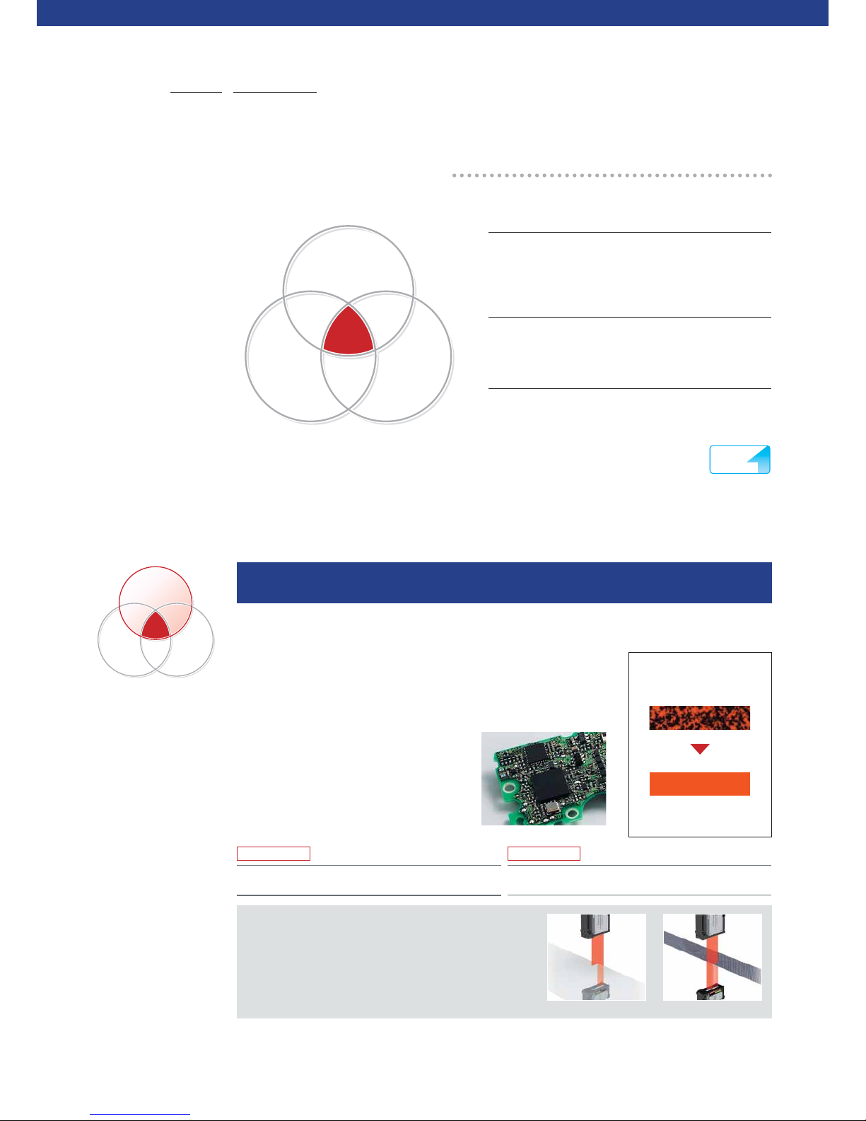
THREE CONCEPTS
The intelligent I-Series consists of a high-accuracy sensor lineup that realises low-cost high
performance with only the most advanced functions for on-site operations.
SERIES
Intelligent
Tough
Easy
I
Intelligent
High accuracy was achieved by using the technology and
functions developed for high-accuracy measuring
instruments.
Tough
Developed for use in harsh environments, the I Series was
designed with a strong structure.
Easy
Excellent usability makes it possible to quickly and easily
perform stable measurements without any difficult
adjustments and settings.
I
-
SERIES
Intelligent Sensor
IG Series
8
High stability and measurement accuracy are achieved
with the newly developed optical system
Multi-Wavelength Laser + I-DSP
With conventional lasers, the transmission spot produces a patchy pattern
(as shown in the figure to the right). This is a laser-specific interference
problem caused by the laser having a single wavelength. The IG Series
sensor overcomes this problem by using a multi-wavelength laser. Because
shadows are formed on the CCD more clearly, the sensor remains highly
stable, even with targets that are conventionally
difficult to detect (e.g. transparent objects). With
the I-DSP (a parallel computing chip)
incorporated in the receiver, the sensor can
perform data processing at high speed,
reducing noise to a minimum.
Page 9

9
Extremely easy to use due to the built-in position monitor
Optic al axis alignm ent in
progress
Red: In dicates
the rece ived light
position
Green:
Indic ates the
measurement
position
Optic al axis alignm ent
complete
Easy to maintain thanks to excellent environment resistance
Example
- Prevent dust or oil f rom adhering to the meas urement unit,
which c an cause an abnormal m easurem ent value.
- Dete ct the intru sion of a different typ e of target .
- Check that a measurement t arget fall s within the measurem ent range.
Although dirt reduces the total amo unt of light
received, the me asurement position is th e same.
The shadow of a ta rget is shown.
No break in the cable after
20 million bends (typical)
Load ( W): 250 g
Bendi ng radius: R 50 mm
Rate: 30 bends/minute
(One bend is a cycl e whereby the
cable is bent fro m left to right and
then from right to lef t.)
90°
R
L
SERIES
Intelligent
Tough
Easy
I
L-C CDL-C CD
Received light level
Received light level
Binarization
level
Binarization
level
28 28
00
SERIES
Intelligent
Tough
Easy
I
IP67 Protection
The enclosure satisfies the IP67 rating based on the IEC
standards and remains watertight even after being held at
a depth of one metre for 30 minutes. The enclosure is
resistant to adverse environments and offers long-term
durability.
Flexible Free-Cut Cable
The sensor head cable is a robot cable that withstands
repeated bending. The cable can be used safely in a
position requiring repeated motion.
Edge Check Function
The user can check whether a measurement is performed
correctly by verifying the number of edges in the field of
view.
Key Point: Less Sensitive to Dirt
Because it uses an L-CCD, the IG Series is less sensitive
to materials such as dirt than a sensor that uses a
photodiode (PD) as the light-receiving element.
Determining the Part of a Target
to be Measured
The position monitor on the IG Series sensors makes it
possible to visually check how a target is detected. The
user can prevent mounting or setting errors by observing
the red lights that indicate the received light position and
the green lights that indicate the measurement position.
Easier Optical Axis Alignment
The position monitor makes it easier to align the optical
axis. Easily perform optical axis alignment by adjusting
the sensor head so that all of the position monitor lights
turn red.
Free Cut!
If the se nsor
gets d irty...
Page 10
1. The DL-RS1A communication unit is required. 2. The screws for connecting the sensor head and bracket are included. 3. The cable is common to the transmitter and receiver, and can be used with either of them.
4. Two cables are included with a sensor head.
IG Series
Cable length Model Weight Piece
2 m
4.
OP-87056
Approx. 80g
1 cable
included
5 m
OP-87057
Approx. 190g
10 m
OP-87058
Approx. 360g
20 m
OP-87059
Approx. 680g
10
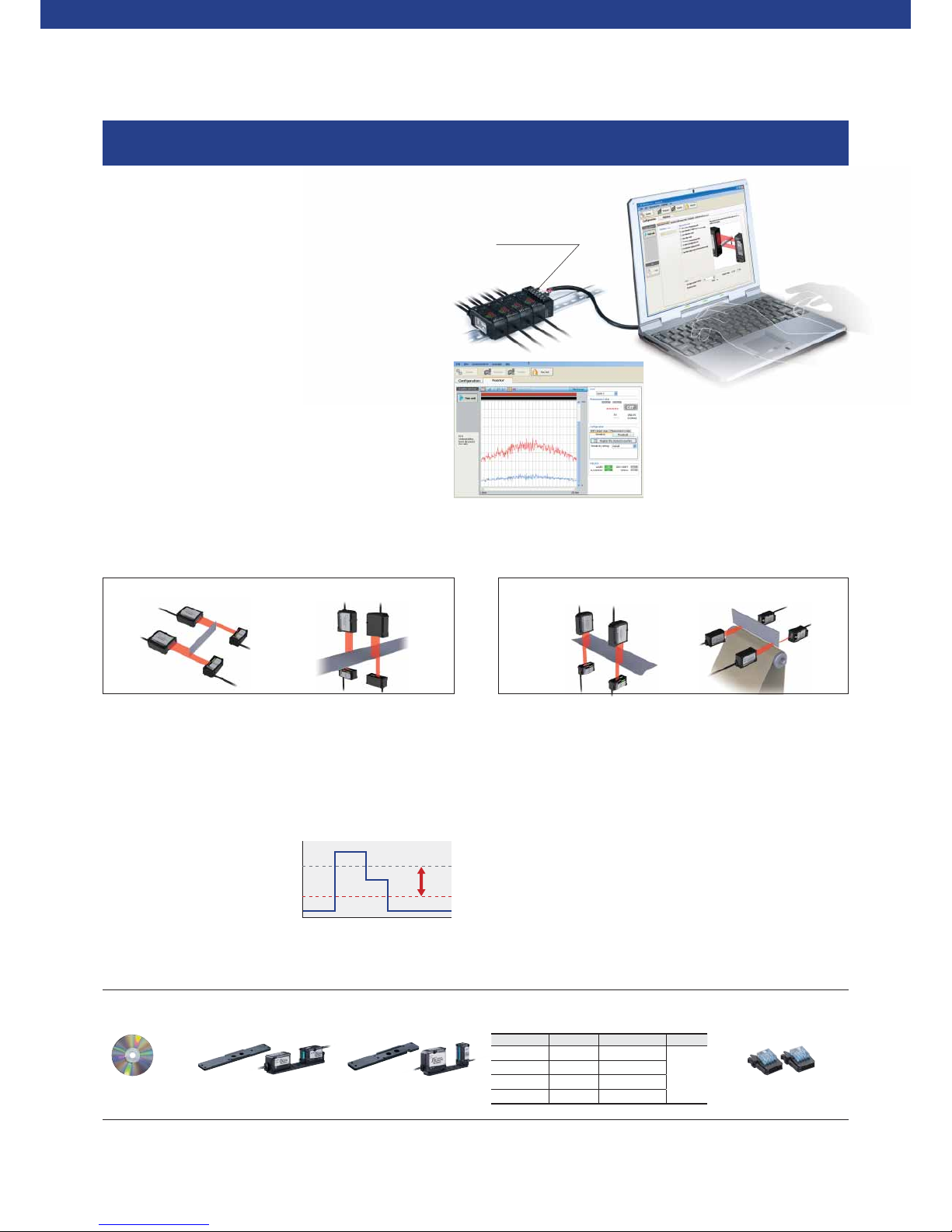
EVEN MORE USEFUL WHEN CONNECTED TO A PC
RS-232C
communication unit
DL-RS1A
Calculation Function
Addition mode
(if a measurement target is large)
SETTING EXAMPLE 1
(length)
SETTING EXAMPLE 2
(width)
Subtraction mode
(to measure the dif ference in level or inclination)
SETTING EXAMPLE 1
(inclination)
SETTING EXAMPLE 2
(difference in thickness)
The confi guration software, IG Confi gurator, allows for a wide range of settings to be made including
the monitoring of the waveforms of received light and the measurement modes.
Sensor head cables
3.
Approx. 50 g Approx. 40 g
PC software
1.
IG-H1
Sensor head mounting
brackets for IG-010
2.
IG-TB01
Sensor head mounting
brackets for IG-028
2.
IG-TB02
Select when a longer cable is required.
Connected connector
with indicator
This connector is required if
the cable is cut.
Connector used to connect to
a display unit (2 pcs.)
OP-84338
Monitoring Function
Measurement conditions such as the waveforms of received
light can be displayed in real time. The mounting and
sensitivity settings can also be adjusted more precisely.
Zero Shift Function
This function shifts an internal measurement value to 0 (to offset
the value). When the target value is changed, this function can be
used to shift an internal measurement value to the new target
value.
Sensitivity Setting
The set value used to judge whether light enters or is blocked,
based on the amount of light received by the CCD, is called the
binarization level. The amount of light received when the reference
waveform is registered is regarded as the 100% level. The light is
judged to be blocked if the
amount of light is less than the
specified binarization level. The
IG Series initially sets a
binarization level of 25% and the
user can change the level
according to the application.
Option
Reading and Writing Settings
The user can enter all settings including the measurement
modes into a PC and then transfer them to the sensor. The
management of setting data is simple and very convenient
when two or more sensors are used.
Received light level
Can be
changed freely
CCD position
100 %
25%
0%
Page 11

11
Specifi cations
Sensor heads
Model IG-010 IG-028
Appearance
Operation principle CCD method
Light source
Visibl e light semic onducto r laser (Wa velengt h:660 n m)
FDA (C DRH) Par t 1040.10
Class 1
1.
IEC60825-1 Class 1
Mounting distance 0 to 1000 m m 0 to 1500 m m
Measu rement ra nge 10 mm 28 mm
Sampling rate 980 µs ( When th e number of ti mes for aver aging is set t o [hsp]: 4 90 µs)
Minimum detectable
object
2.
High sensitivity mode
ø0.1 mm (S etting dis tance : 100 mm)
Standard mode
ø0.2 m m (Setti ng distanc e: 40 mm or less),
ø0.5 mm ( Setting d istance : 500 mm)
ø0.2 m m (Setti ng distanc e: 50mm or less),
ø0.5 mm ( Setting d istance : 500 mm)
Repeatabilit y
3.
5 µm (Se tting dist ance: 10 0 mm)
10 µm (Se tting dist ance: 5 00 mm)
80 µm (Settin g distanc e: 1000 mm )
5 µm (Se tting dist ance: 10 0 mm)
10 µm (Se tting dist ance: 5 00 mm)
80 µm (S etting di stance : 1000 mm)
140 µm (S etting d istance : 1500 mm )
Linearity
4.
±0. 28 % of F.S. (±28 µm ) ±0.1 % of F.S. (± 28 µm)
Temper ature char acteris tics
5.
±0.0 3 % of F.S./° C (±3 µm/ °C) ±0.0 1 % of F.S./° C (±3 µm/ °C)
Operation
indicator
Tran smit ter Optic al axis alig nment indi cator: Gre en LED / Pow er indicat or: Green L ED
Receiver Optic al axis alig nment indi cator: Gre en LED / Posi tion monito r: Dual bar L ED (Red, Gr een)
Environment
resistance
Enclosure rating IP67
Ambient temperature -10 to +45 °C (No free zing)
Ambient humidity 35 to 85 % RH (No cond ensatio n)
Ambient light
6.
Inca ndescen t lamp: 50 00 lux Sunl ight: 50 00 lux
Vibration 10 to 55 Hz D ouble ampli tude 1.5 mm X YZ each ax is: 2 hours
Material
Case Zinc die -cast ( Lower ca se), PBT ( Upper ca se), Poly arylat e (PAR) (Dis play part ), SUS3 04 (Meta llic part)
Lens cover Glass
Cable PVC
Supplied item Transmi tter × 1, Rec eiver × 1, Sens or head ca bles (2 m) × 2
Weigh t (includin g supplied it ems) Appro x. 380 g Approx. 5 00 g
1. The classifi cation for FDA (CDRH) is implemented based on IEC60825-1 in accordance with the requirements of Laser Notice No.50.
2. When the measurement target object is measured at the centre position of the setting distance.
When the measurement mode is set to the glass edge mode, a glass edge of C0.1 mm or more can be detected (Setting distance: 500 mm).
3. When the light is shielded by half at the centre position of the setting distance. Vibration width when the average number of times is set to 16 and sampling is performed for 30 seconds.
(When the analogue output is used, the margin of error of analogue output is added.)
4. When the setting distance is 100 mm and light is shielded at 50 mm position from the receiver. Margin of error to the ideal line.
5. When the setting distance is 100 mm and light is shielded by half at 50 mm position from the receiver.
6. Excluding when the average number of times is set to [hsp].
Display unit (amplifier)
Model IG-1000 IG-1050 IG-1500 IG-1550
Appearance
Amplifier type DIN rail mount Panel mount
Main unit/Ex pansion unit Main unit Expansion unit Main unit Expansion unit
Analogue output Yes No Yes No
Power s upply volt age 10-3 0 VDC, Ripple ( P-P): 10% in cluded, Cl ass 2 or LPS
Power c onsumpt ion
4.
(incl uding analog ue curren t
output)
Normal 2700 mW o r less (at 3 0 V: 90 mA or le ss) 2880 m W or less (a t 30 V: 96 mA or le ss)
Power s aving fun ction (HA LF) 230 0 mW (at 30 V: 77 m A or less)
Power s aving fun ction (AL L) 220 0 mW (at 30 V: 74 mA o r less)
Digital display method Dual 7-seg display / Upper level: Red, 5 digits / Lower level: Green, 5 digits
Dual 7-seg display / Upper level: Red/ Green, 2 colours, 5 digits / Lower level: Green, 5 digits
Displ ay range -99.9 99 to +99 .999, -99 .99 to +99. 99, -99.9 to + 99.9, -9 9 to +99 (se lectabl e)
Display resolution 1 µm, 10 µm, 10 0 µm , 1000 µm (sele ctable )
Output
Judge ment outpu t (select able
bet ween NPN and P NP)
NPN (P NP) open coll ector x3 ch, 30 VDC (P ower suppl y voltage ) or less, re sidual vol tage 1 V (2 V) o r less, N.O. /N.C. sel ectable Ma x. 50 mA /ch
1.
Response time
(judgement output)
1.96 to 40 31.72 ms
2.
Edge ch eck outpu t (select able
bet ween NPN and P NP)
NPN (P NP) open coll ector x1ch , 30 VDC (Pow er supply vo ltage) or l ess, resi dual volta ge 1 V (2 V) or le ss, N.O./ N.C. selec table Max. 50 mA,
1.
respo nse time 20 m s
Analogue output
(sele ctable amo ng ±5V,
1-5 V, 0-5 V, 4- 20 mA)
Input
Gain input Input t ime: 20 ms or m ore, Resp onse dela y time: 120 ms o r less (Non volatile me mory (E EPROM) 1.5 s or l ess)
Rese t input Input t ime: 20 ms or m ore, Resp onse dela y time: 20 ms o r less
Timing input Inpu t time: 2 ms or m ore, Resp onse dela y time: 2 ms or l ess
Zero s hift input Input t ime: 20 ms or m ore, Resp onse dela y time: 20 ms o r less
Bank A in put/B ank B input Input time : 20 ms or more , Respons e delay time : 20 ms or les s
2.
Lase r emission s top input Input t ime: 2 ms or mo re, Respo nse delay ti me: 2 ms or le ss
Environment resistance
Ambient temperature -10 to + 50°C (N o freezin g)
Ambient humidity 35 t o 85%RH (N o condens ation)
Vibration 10 to 55 Hz Do uble ampli tude 1.5 mm XY Z each ax is: 2 hours
Pollution degree 2
Material Cas e/Fron t sheet: P olycarb onate, Ke y top: Polya cetal, Ca ble: PVC
Supplied item Mai n body × 1, Instr uction ma nual × 1 (only f or main unit)
Main bo dy × 1, Panel mou nting bra cket × 1, Front pr otection c over × 1, Power
suppl y and input /output c able (2 m) × 1,
Exp ansion cab le (50 mm) × 1 ( only for exp ansion unit ),
Instr uction ma nual × 1 (only f or main unit)
Weigh t (includin g supplied it ems) Appro x. 150 g Appro x. 140 g Appr ox. 170 g Appr ox. 165 g
1. When expansion units are added: Max. 20 mA/ch
2. For more details, refer to the User’s Manual.
3. Delay time that occurs from the analogue output circuit after the judgment is output.
4. When adding an expansion unit, the consumed electrical power is equal to the total value of the consumed electrical power of all amplifi ers.
Volta ge output Cur rent outp ut
Output range ±5 V (f ull scale 10 V ) 4-20 m A (full sca le 16 mA)
Output resistance 100 Ω
-
Maxi mum load resi stance
-
350 Ω
Repetition accuracy ±1 mV ±1.5 µA
Display accuracy ±0.0 5 % of F.S. ±0. 25 % of F.S.
Temperature characteristics ±0.0 05 % of F.S./ °C ±0.01% of F.S./ °C
Update cycle Sa me as senso r head sam pling cycle
Response time Same as Res ponse tim e (judgem ent outpu t)
Time constant
3.
10 µs (90 % r esponse ) 30 µs (9 0 % respon se)
Page 12

IB Series
12
Achieving an Endless Amount of Applications Unable to be
Detected by Using a Fibre Sensor
IB-10
IB-05
IB-30
DIN-rail mount type
IB-1000/1050
Panel mount type
IB-1500/1550
IB-01
Thrubeam Type Laser Detection Sensor
IB S eries
High-speed sampling of 80 µs
High-accuracy differentiation of 5 µm
New function: Auto adjustment included
Page 13

13
3 devices are required each for
presence/absence, height and timing
detections
All detections conducted using a single device
❚ Photoelectric sensor ❚ Digital laser sensor
As the position changes, the
thrubeam light volume changes
Regardless of position, the thrubeam light volume
remains the same
Detection is not possible when
strayed off the linear optical axis
Definitive detection in a wide detection area
Does not stabilise due to the subtle
difference in thrubeam light volume
Definitive determination of even the most minute
thrubeam light volume difference
Sensitivity changes according to the
influence of dirt, etc
Dirt is eliminated using the Light intensity correction
function
1 device, 3 roles. 3 step output of
presence and size
Upper/lower output-equipped as standard. Not only
presence/absence is detected, but size judgments can also
be conducted using this single device. A timing sensor is also
not required due to the presence of the Auto timing function.
Not influenced by passage position
According to the parallel laser light, no matter where the
target is positioned, the judgment values will remain the
same. This makes high-accuracy differentiation possible
anywhere on the detection area.
No concern of position
misalignment even in wide areas
As the maximum width of the optical axis is 30 mm, stable
detection is possible even if the target is shaking.
Not affected by dirt or temperature
changes
By incorporating a Light intensity correction function, the
numerical margin of error caused by aging variation can be
cancelled. Possible to always achieve stable, high-accuracy
judgments.
High-accuracy detection even in
transparent bodies
In addition to detecting the presence of transparent targets,
detections such as those of single/double transparent films,
density differentiation, and the turbidity of liquids is also
possible. Furthermore, using the percentage display function
the thrubeam rate judgment is also possible.
Page 14

SERIES
Intelligent
Tough
Easy
I
IB Series
Low-cost
High
Performance
THREE CONCEPTS
The intelligent I-Series consists of a high-accuracy sensor lineup that realises low-cost high
performance with only the most advanced functions for on-site operations.
SERIES
Intelligent
Tough
Easy
I
Intelligent
High accuracy was achieved by using the technology and
functions developed for high-accuracy measuring
instruments.
Tough
Developed for use in harsh environments, the I Series was
designed with a strong structure.
Easy
Excellent usability makes it possible to quickly and easily
perform stable measurements without any difficult
adjustments and settings.
14
Mechanism behind stable detection
Light-receiving element (high-sensitivity PD)
Protective glass
Light-receiving lens
Adopting the newly developed optical system used in the IG Series
Multi-Wavelength Laser Beam + High-sensitivity PD
Normal lasers are single wavelength, therefore due to friction, the pattern
becomes patchy, as shown in the diagram on the right. This problem is rectified
in the IB Series by utilising laser light with multiple wavelengths. Targets with a
high level of difficulty can still be detected with a high degree of stability.
Furthermore, by incorporating a high-sensitivity PD within the light receiving
section data can be processed at high speeds, reducing the extraneous
fluctuations to the absolute limit.
SPOT IMAGE
Singl e-wavelength las er
(conventional laser sensor)
A patchy pattern appears.
Due to the mult i-wavelength
laser used, t he beam pattern
has a more unif orm intensity
distribution.
Multi-wavelength laser (IB)
High-accuracy differentiation
of 5 µm
Ultra-long distance
of 2 m
I
-
SERIES
Intelligent Sensor
Page 15
Display value
Time progressed
0
%
100
%
90
%
Auto adjustment function ON
Auto adjustment
function OFF
Automatically adjusts
the received light volume
to the standard value
15
Using the transmission lens, after the laser light
emitted as a parallel beam passes through the light
receiving lens, the light is then converged to the
light-receiving element (high-sensitivity PD). When
the measurement target interrupts this parallel
beam, this beam is in proportion to the volume of
interrupted light and the light entering the received
light element reduces. When this occurs, by
capturing the light volume in the light-receiving
element (high-sensitivity PD), the size and
transparency of the target can be measured.
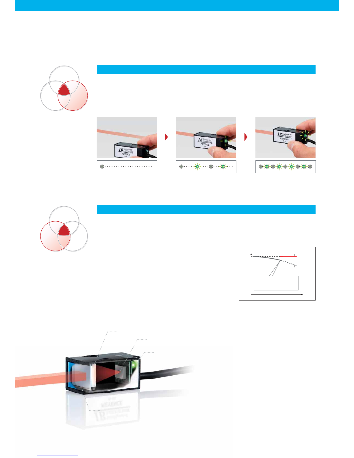
If the optical axis is not aligned the LED
turns off
When the optical axis begins to align, the
flashing frequency of the LED quickens
High-speed flashing when the optical
axis is aligned
Semi-conductor laser
Alignment LED
Protective glass
Transmission lens
SERIES
Intelligent
Tough
Easy
I
SERIES
Intelligent
Tough
Easy
I
Maintenance-saving according to the Auto adjustment function
Long-term, stable detection even in environments where the
device becomes dirty easily
In the IB Series, should the received light volume decrease
according to such things as dirt on the front of the sensor
head, by using the adjustment input, the received light volume
is adjusted to standard values during input. In addition, the
Auto adjustment function recognises that this adjustment
input has no measurement target, and therefore is executed
regularly automatically. Even when used in environments
where the device becomes dirty easily, stable measurements
and a high degree of maintenance-saving has been achieved
by the device automatically correcting itself.
Simple positioning according to the alignment LED
Easy to align the optical axis
As the optical axis of the laser align, the flash frequency of the laser transmitter indicator quickens. Even
without looking at the amplifier unit, the optimum position can be achieved easily.
Page 16

IB Series
16
Specifi cations
Sensor head
Model IB-01 IB-05 IB-10 IB-30
Appearance
Light source Visibl e semicond uctor las er Wavelen gth: 66 0 nm
Lase r Class Class 1 ( IEC608 25-1, FDA (CD RH) Part 1040.10
1.
)
Mounting distance 0 t o 2000 mm 0 to 300 m m
Measu rement ra nge
Ø1 mm
(Inst allation di stance 0 t o 300 mm)
Ø1 to 2.5 mm ( Install ation dista nce
300 to 2000 m m)
5 mm 10 m m 30 mm
Sampling rate 12,50 0 times/ sec. (8 0 µs)
Minimum
detectable object
2.
Ø8 µm
(Inst allation di stance 0 t o 300 mm)
Ø8 to 50 µm
(Inst allation di stance 3 00 to 200 0 mm)
Ø0.05 mm Ø0.1 mm Ø0. 2 mm
Repeatabilit y
3.
5 µm
(dist ance 0 to 30 0 mm)
5 µm 5 µm 10 µm
Temperature characteristics
4.
±0. 2% of F.S./° C ±0.1% of F.S. /°C (± 5 µm) ±0.1% of F.S. /°C (±10 µm ) ±0.1% of F.S. /°C (± 30 µm)
Operation indicator Lase r emission w arning indi cator: gr een LED
Environmental resistance
Ambient luminance
Inca ndescen t lamp: 50 00 lux
Solar light: 10000 lux
Inca ndescen t lamp: 50 00 lux
Solar li ght: 500 0 lux
Incandescent lamp: 10000 lux
Solar light: 10000 lux
Ambient temperature 0 to +4 0°C (no fre ezing) 0 to +5 0°C (no fre ezing)
Ambient humidity 35 to 85% RH (no con densatio n)
Vibration 10 to 55 Hz Do uble ampli tude 1.5 mm XY Z each ax is: 2 hours
Material
Case PB T Galva nized die c ast
Lens cover Glass
Cable PVC (2 m )
Weight Appro x. 140 g Appro x. 180 g Approx . 220 g Appr ox. 510 g
1. The classification for FDA (CDRH) is implemented based on IEC60825-1 in accordance with the requirements of Laser Notice No.50.
2. Value when measuring the target (white diffuse object) at the middle of the transmitter and receiver position, and at the centre of the measurement range.
3. When distance between transmitter and receiver is set to 300 mm, and light is half-shielded at a position 150 mm from receiver.
Deflection width (±2σ) when sampled for 30 seconds with an average number of times set to 64 times.
4. When distance between transmitter and receiver is set to 100 mm and full light is received.
Amplifi er unit
Model IB-1000 IB-1500 IB-1050 IB-1550
Appearance
Amplifier type DIN rail mount Pan el mount DIN rail mount Panel mount
Main unit/Ex pansion unit Main unit Expansion unit
Head compatibilit y Yes
Display
Display resolution 0.01% , 0.1%, 1% (switc hable)
Displ ay range – 99.999 to 9 9.999, – 99.99 to 99. 99, –99.9 t o 99.9, –9 9 to 99 (swit chable)
Digital display method
Dual 7-s egment dis play
Upper level: 5 red digits
Lower level: 5 green digits
Dual 7-s egment dis play
Upper l evel:2 -colour (g reen/ red) 5
digits
Lower level: 5 green digits
Dual 7-s egment dis play
Upper level: 5 red digits
Lower level: 5 green digits
Dual 7-s egment dis play
Upper level: 2-colour (gr een/red) 5 digits
Lower level: 5 green digits
Operation indicator
Judgm ent indica tor: 2-co lour (gree n/red ) LED (HI, GO, L O),
Bank in dicator: G reen LED x 4,
Lase r emission w arning indic ator: Gre en LED,
Othe rs: Gree n LED x 8, red LE D x 3
Analo gue voltag e output
1.
±5 V, 1 to 5 V, 0 to 5 V Ou tput impe dance 100 Ω
No
Analo gue curren t output
1.
4 to 20 mA M aximum lo ad resist ance 350 Ω
Control
input
2.
Bank s witch inpu t
Non-v oltage inp ut
Zero-shift input
Lase r emission s top input
Timing input
Rese t input
Adjust input
Control
output
3.
Judgment output
Open c ollector ( NPN/P NP switcha ble, N.O./ N.C. swit chable)
Check output
Power supply
Power v oltage 10 to 30 VD C, including r ipple (P-P ) 10% Class 2 or L PS Suppli ed from main u nit
Power c onsumpt ion
4.
1950 mW or l ess
(at 30 V, 6 5 mA max.)
2100 mW or l ess
(at 30 V, 70 m A max.)
1950 mW or l ess
(at 30 V, 6 5 mA max.)
2100 mW or l ess
(at 30 V, 70 m A max.)
Environmental resistance
Ambient temperature -10 to +50 °C (No free zing)
Ambient humidity 35 to 85 % RH (No cond ensatio n)
Vibration 10 to 55 Hz D ouble ampli tude 1.5 mm X YZ each ax is: 2 hours
Pollution degree 2
Material Case /Front p anel: pol ycarbon ate, key top: poly acetal, c able: PV C
Weigh t (includin g supplied it ems) Appro x. 150 g Appr ox. 170 g Appro x. 140 g Appr ox. 165 g
1. ±5 V, 1 to 5 V, 0 to 5 V, or 4 - 20 mA should be selected.
2. The four external input wires are assigned with desired inputs.
Rated no-voltage input: ON voltage 2 V or less, OFF current 0.05 mA or less
Rated voltage input: Max. input rating 30 V or less, ON voltage 7.5 V or more, OFF current 0.05 mA or less
3. Rated NPN open collector output: Max. 50 mA/ch (20 mA/ch when expansion units are connected), 30 V or less, residual voltage 1 V or less
Rated PNP open collector output: Max. 50 mA/ch (20 mA/ch when expansion units are connected), 30 V or less, residual voltage 2 V or less
4. The power consumption with slave units installed is the total of each amplifier unit’s power consumption.
Example: When using one master unit (IB-1000) with two slave units (IB-1050) (1950 mW X 1) + (1950 mW X 2) = 5850 mW
Page 17

IG/IB Series
Models
Communication
method
Connection
device
Read judgment
results
Read
measurement
values
Control
input
Change tolerance
values
Comments
DL-RS1A
RS-232C
PLC PCs of
various
companies
✓✓✓✓
Uses no control sequence
communication. Communicates by
using a communication program.
DL-RB1A
BCD output
PLC PCs of
various
companies
X
✓
XX
Measurement values are updated
by synchronising with the input
terminals. Furthermore, updates
automatically occur using a timer.
Readouts are created by
synchronising with the strobe
output.
17
DATA COMMUNICATION (Common to IG/IB)
The setting can be changed.
Setting value Description
Not output
Analog ue output afte r the judgemen t value is convert ed to the range fro m 0 to 5 V.
Analog ue output afte r the judgemen t value is convert ed to the range of ± 5 V.
Analog ue output afte r the judgemen t value is convert ed to the range fro m 1 to 5 V.
Analog ue output afte r the judgemen t value is convert ed to the range fro m 4 to 20 mA.
Amplifier Function
Communication Unit
NPN/PNP Output Selection (judgment selection)
Both NPN and PNP outputs are supported. The outputs are set
the first time the user turns on the power. These settings can
subsequently be changed. Judgments are output as HIGH, GO,
or LOW.
Analogue Output Selection
The following four types of analogue outputs can be selected.The
output is selected the first time the user turns on the power.
DL-RB1A
BCD output unit
Use this unit when retrieving numerical data
from the IG/ IB Series to an external device as
digital data. A single communication unit can
retrieve data from up to four IG/IB Series display
units in BCD.
DL-RS1A
RS-232C communication unit
Use this unit when outputting digital data to
an external device with RS-232C signals. It
is necessary to connect it to a PC when
using the startup support software, IG
Configurator. A single communication unit
can retrieve data from up to four IG/IB Series
display units.
Bank Function
The bank function can register up to four patterns of specific
settings.* For example, in response to a measurement target
changeover, this function allows the user to easily switch between
the patterns of registered settings.
* HIGH set ting value, LOW setting valu e, binarization level,
shift targ et value, etc.
Page 18

(26)
ø9
2-ø3.4
(Mounting hole)
17
ø4.8
Cable length 170
Edge M8 connector
39.8
54.7
6.7
3.2
25.4
Transmission spot centre
23
11. 2
18.8
31.8
3-M3 Valid screw depth 4
10.4
1.6
50.5
32.7
10.6
4.8
6.7
3.7
* Transmission spot (reference value)
12
15
Base level
2-M4 Valid screw depth 5.2
Measurement
centre
* Light-receiving area
(5 × 14 rectangle)
31.8
18.8±1
11. 2
23
51.5
12.6
23.5
28.5
55
16.2
2-ø3.4
(Mounting hole)
(26)
ø9
3-M3 Valid screw depth 4
3
49.4
4.3
13.5
Base level
2-M4 Valid screw depth 5.2
ø4.8
Cable length 170
Edge M8 connector
* Light-receiving area
(3.6 × 31.2 rectangle)
Measurement
centre
56.2
33.1±0.3
11. 4
23
48.2
4.1
2-ø4.5
(Mounting hole)
7
17.1
11. 4
30.2
29.3
15.5
4.3
2.5
18.5
16.6
0.8
3-M3 Valid screw depth 5.5
Base level
Base level
2-M5 Valid screw
depth 5.2
47.6
16.6
6.4
(26)
ø9
18.8
25.4
11. 5
66.2
4.2
47.5
11. 4
23
33.1
56.2
3-ø4.5
(Mounting hole)
Transmission spot centre
4-M3 Valid screw depth 5.5
63.8
43.8
6.5
4.8
10.4
Base level
10.4
1.8
12
33
* Transmission spot
(reference value)
3-M5 Valid screw depth 5.2
Base level
Edge M8 connector
Edge M8 connector
(26)
ø9
ø4.8
Cable length 170
ø4.8
Cable length 170
50
26
56
(4.2)
(10.2)
(146.4)
11.4
28
6.1
16.4
61.2
61.2
28
38.1±0.3
(17.6)
(45.6)
(24.1)
(52.1)
17
46.7
82.7
11.5
23
11.4(Measurement centre)
Measurement area
Transmitter Receiver
40
151.1
144
23
36.8
36.8
22
23.8±1
10
56.4
(47.6)
11.5
67.9
17
(18.8)
(28.8)
(66.2)
(12.3)
(22.3)
11.4
(Measurement centre)
Measurement area
2-ø4.5 Drilled through hole
ø8.5 Spot facing depth 4
Transmitter Receiver
2-ø4.5 Drilled through hole
ø8.5 Spot facing depth 4
Material: Aluminium Material: Aluminium
IG/IB Series
Unit : mm
Dimensions
IG Series Sensor head
IG Series Sensor head mounting bracket
IG-010
IG-028
IG-TB01 + IG-010 IG-TB02 + IG-028
Transmitter
Transmitter
Receiver
Receiver
18
Page 19

2-ø3.2
(Mounting hole)
7
2.5
16.1
19
12.2
ø4
Cable length 2 m
Slit (1×5)
18
18
7
3.7
ø6
ø4
Cable length 2 m
2.5
37
2-ø3.2
(Mounting hole)
12.2
16
18
* Transmission spot (reference value)
(6×8 ellipse)
2.5
25.2
15.0
15.6
2.6
20.0
2-ø3.2
(Mounting hole)
2.6
ø4
Cable length 2 m
* Light-receiving area (3.5 ×3.5)
2.6
2.6 31.0
2-ø3.2
(Mounting hole)
2.5
36.2
15.0
15.6
ø4
Cable length 2 m
* Transmission spot (reference value)
When distance is 300 mm: approximately ø 1 mm
When distance is 2000 mm: approximately ø 2.5 mm
18
28
7
ø4
Cable length 2 m
2.5
2-ø3.2
(Mounting hole)
13
13.8
Slit (1×10)
20
3.7
7
ø6
2.5
ø4
Cable length 2 m
2-ø3.2
(Mounting hole)
13.8
25
50
20
*Transmission spot (reference value)
(7×13 ellipse)
52
44
4
4
44
3-ø4.5
(Mounting hole)
12
20
28
64
ø4
Cable length 2 m
Slit (1×30)
68
60
3-ø4.5
(Mounting hole)
44
4
4
12
28
20
64
ø4
Cable length 2 m
*Transmission spot (reference value)
(6×36 rectangle)
20
20
28.3
8.9
18.5
Cable diameter ø4.8
Cable diameter ø4.7
Cable length 2 m
18.5
37.4
42.4
17.4
3
20
21.6
35.4
76.3
17.6
Max.135°
When the cover is
open: Max. 109.2
Min.15
Min.15
37.4
42.4
17.4
3
20
21.6
35.4
76.3
17.6
Max.135°
When the cover is
open: Max.109.2
18.5
18.5
1.9
(4.8)
19.2
69.5
8.9
Cable diameter ø4.8 Cable diameter ø4.7
Cable length 2 m
Min.15
Min.15
28.3
44.7
2.3
7.6
1.5
48
73.6
19.1
10.3
19.1
17.6
27.2
44.7
15.3
9.5
35
20.2
4
62.5
12.4
Panel thickness
1 to 6 mm
45mm
+
0.6
-
0
45mm
+
0.6
-
0
Min.85mm
Xmm
45mm
+
0.6
-
0
X = 48 × (number of amplifiers) - 3
Cable diameter ø4.8
Cable diameter ø4.7
Cable length 2 m
76
22.4
10.3
IG/IB Series
Unit : mm
Dimensions
IB Series Sensor head
Sensor amplifi er
(DIN rail mount type)
Sensor amplifi er
(Panel mount type)
IB-01
IB-10
IB-05
IB-30
Receiver
Transmitter
Transmitter
Receiver
Receiver
Transmitter
Transmitter
IG (IB)-1050IG (IB)-1000
Receiver
IG (IB)-1000/IG (IB)-1050
IG (IB)-1500/IG (IB)-1550
19
Page 20

WW1-1010
www.keyence.com
SAFET Y INFORM ATION
Please read the instruction manual carefully in
order to safely operate any KEYENCE product.
Please visit:
SINGAPORE
Phone: +65-6392-1011 Fax: +65-6392-5055
SLOVAKIA
Phone: +421 2 5939 6461 Fax: +421 2 5939 6200
MEXICO
Phone: +52-81-8220-7900 Fax: +52-81-8220-9097
NETHERLANDS
Phone: +31 40 20 66 100 Fax: +31 40 20 66 112
POLAND
Phone: +48 71 36861 60 Fax: +48 71 36861 62
MALAYSIA
Phone: +60-3-2092-2211 Fax: +60-3-2092-2131
CZECH REPUBLIC
Phone: +420 222 191 483 Fax: +420 222 191 505
AUSTRIA
Phone: +43 22 36-3782 66-0 Fax: +43 22 36-3782 66-30
BELGIUM
Phone: +32 27 16 40 63 Fax: +32 27 16 47 27
CHINA
Phone: +86-21-68757500 Fax: +86-21-68757550
CANADA
Phone: +1-905-696-9970 Fax: +1-905-696-8340
FRANCE
Phone: +33 1 56 37 78 00 Fax: +33 1 56 37 78 01
KOREA
Phone: +82-31-642-1270 Fax: +82-31-642-1271
GERMANY
Phone: +49 61 02 36 89-0 Fax: +49 61 02 36 89-100
HUNGARY
Phone: +36 1 802 73 60 Fax: +36 1 802 73 61
HONG KONG
Phone: +852-3104-1010 Fax: +852-3104-1080
ITALY
Phone: +39-02-6688220 Fax: +39-02-66825099
JAPAN
Phone: +81-6-6379-2211 Fax: +81-6-6379-2131
SWITZERLAND
Phone: +41 43-45577 30 Fax: +41 43-45577 40
THAILAND
Phone: +66-2-369-2777 Fax: +66-2-369-2775
TAIWAN
Phone: +886-2-2718-8700 Fax: +886-2-2718-8711
UK & IRELAND
Phone: +44-1908-696900 Fax: +44-1908-696777
USA
Phone: +1-201-930-0100 Fax: +1-201-930-0099
KEYENCE GLOBAL HEADQUA RTERS
1-3-14, Higashi-Nakajima, Higashi-Yodogawa-ku, Osaka, 533-8555, Japan PHONE: +81-6-6379-2211
Copyright (c) 2010 KEYENCE CORPORATION. All rights reserved. IBIG-AS-C-E 1080-1 600863 Printed in Japan
The information in this publication is based on KEYENCE’s internal research/evaluation at the time of release and is subject to change without notice.
*600863*
IG/IB Series
Unit : mm
Dimensions
70
35.4
21.1
43.8
22.5
(48.2)
37.2
70
35.4
21.1
53.4
37.1
22.5
(57.8)
Communication unit
(BCD output type)
DL-RB1A
Communication unit
(RS-232C communication type)
DL-RS1A
34-pin MIL connector
DIN-rail mount DIN-rail mount
 Loading...