


INSTRUCTION MANUAL
144/440 MHz FM DUAL BANDER
TM-D710A
144/430 MHz FM DUAL BANDER
TM-D710A/ TM-D710E
Only basic operations are explained in this instruction manual. For a detailed explanation on the operations, refer to the PDF file supplied on the CD-ROM.
This equipment complies with the essential requirements of Directive 1999/5/EC.
The use of the warning symbol means the equipment is subject to restrictions of use in certain countries.
This equipment is intended for use in all EU countries and CH, LI, IS and NO, and requires a license.
© B62 1986 00 (K, E, M4)
09 08 07 06 05 04 03 02 01 00

Thank You
We are grateful you decided to purchase this Kenwood FM transceiver. Kenwood always provides Amateur Radio products which surprise and excite serious hobbyists. This transceiver is no exception. Kenwood believes that this product will satisfy your requirements for both voice and data communications.
Features
This transceiver has the following main features:
•Has a built-in TNC which conforms to the AX.25protocol. With a portable computer, allows you to enjoy Packet operation quite easily.
•Includes a program for dealing with data formats supported by Automatic Packet/ Position Reporting System (APRS®).
•Enhanced Programmable Memory (PM) channels store virtually entire current operating environments for your quick recall.
•Contains a total of 1000 Memory channels to program frequencies and other various data. Allows each Memory channel to be named using up to 8 alphanumeric characters.
•Continuous Tone Coded Squelch System (CTCSS) or Digital Code Squelch (DCS) rejects unwanted calls from other stations.
Writing Conventions Followed in this Manual
The writing conventions described below have been followed to simplify instructions and avoid unnecessary repetition.
Instruction |
Action |
|
|
|
|
Press [KEY]. |
Momentarily press KEY. |
|
|
|
|
Press [KEY] (1s). |
Press and hold KEY for 1 second or longer. |
|
|
|
|
Press [KEY1], [KEY2]. |
Press KEY1 momentarily, release KEY1, then press |
|
KEY2. |
||
|
||
|
|
|
Press [F], [KEY]. |
Press the F key to enter Function mode, then press |
|
KEY to access its secondary function. |
||
|
||
|
|
|
Press [KEY] + Power ON. |
With the transceiver power OFF, press and hold |
|
KEY while turning the transceiver power ON. |
||
|
||
|
|
Information on Disposal of Old Electrical and Electronic Equipment (applicable for EU countries that have adopted separate waste collection systems)
Products with the symbol (crossed-out wheeled bin) cannot be disposed as household waste.
Old electrical and electronic equipment should be recycled at a facility capable of handling these items and their waste byproducts. Contact your local authority for details in locating a recycle facility nearest to you. Proper recycling and waste disposal will help conserve resources whilst preventing detrimental effects on our health and the environment.

Notices to the User
One or more of the following statements may be applicable:
FCC WARNING
This equipment generates or uses radio frequency energy. Changes or modifications to this equipment may cause harmful interference unless the modifications are expressly approved in the instruction manual. The user could lose the authority to operate this equipment if an unauthorized change or modification is made.
INFORMATION TO THE DIGITAL DEVICE USER REQUIRED BY THE FCC
This equipment has been tested and found to comply with the limits for a Class B digital device, pursuant to Part 15 of the FCC Rules. These limits are designed to provide reasonable protection against harmful interference in a residential installation.
This equipment generates, uses and can generate radio frequency energy and, if not installed and used in accordance with the instructions, may cause harmful interference to radio communications. However, there is no guarantee that the interference will not occur in a particular installation. If this equipment does cause harmful interference to radio or television reception, which can be determined by turning the equipment off and on, the user is encouraged to try to correct the interference by one or more of the following measures:
•Reorient or relocate the receiving antenna.
•Increase the separation between the equipment and receiver.
•Connect the equipment to an outlet on a circuit different from that to which the receiver is connected.
•Consult the dealer for technical assistance.
WHEN CONDENSATION OCCURS INSIDE THE TRANSCEIVER
Condensation may occur inside the transceiver in such a case where the room is warmed using a heater on cold days or where the transceiver is quickly moved from a cold room to a warm room. When condensation occurs, the microcomputer and/or the transmit/receive circuits may become unstable, resulting in transceiver malfunction. If this happens, turn OFF the transceiver and just wait for a while. When the condensation droplets disappear, the transceiver will function normally.
υEXPLOSIVE ATMOSPHERES (GASES, DUST, FUMES, etc.)
Turn OFF your transceiver while taking on fuel or while parked in gasoline service stations. Do not carry spare fuel containers in the trunk of your vehicle if your transceiver is mounted in the trunk area.
υINJURY FROM RADIO FREQUENCY TRANSMISSIONS
Do not operate your transceiver when somebody is either standing near to or touching the antenna, to avoid the possibility of radio frequency burns or related physical injury.
υDYNAMITE BLASTING CAPS
Operating the transceiver within 150 m (500 feet) of dynamite blasting caps may cause them to explode. Turn OFF your transceiver when in an area where blasting is in progress, or where “TURN OFF TWO-WAY RADIO” signs have been posted. If you are transporting blasting caps in your vehicle, make sure they are carried in a closed metal box with a padded interior. Do not transmit while the caps are being placed into or removed from the container.
Precautions
Observe the following precautions to prevent fire, personal injury, and transceiver damage.
•When operating mobile, do not attempt to configure the transceiver while driving; it is too dangerous.
•Do not transmit with high output power for extended periods. The transceiver may overheat.
•Do not disassemble or modify the transceiver for any reason, unless instructed by this manual or by Kenwood documentation.
•Do not expose the transceiver to long periods of direct sunlight, nor place it near heating appliances.
•Do not place the transceiver in excessively dusty, humid, or wet areas, nor on unstable surfaces.
•If an abnormal odor or smoke is detected coming from the transceiver, switch the transceiver power off immediately, and contact a Kenwood service station or your dealer.
•Use of the transceiver while you are driving may be against traffic laws. Please check and observe the vehicle regulations in your area.
•Do not use options not specified by Kenwood.
υThe transceiver is designed for a 13.8 V DC (±15%) power source! Never use a 24 V battery to power the transceiver. Check the battery polarity and voltage of the vehicle before installing the transceiver.
υUse only the supplied DC power cable or a Kenwood optional DC power cable.
υDo not insert metal objects into the cooling fan.
υDo not cut and/or remove the fuse holder on the DC power cable. Improper connections and/or current surges may cause smoke or fire.
υFor passenger safety, install the transceiver securely using the supplied mounting bracket and screw set so the transceiver will not break loose in the event of a collision.
υVarious electronic equipment in your vehicle may malfunction if they are not properly protected from the radio frequency energy which is present while transmitting. Electronic fuel injection, anti-skid braking, and cruise control systems are typical examples of equipment that may malfunction. If your vehicle contains such equipment, consult the dealer for the make of vehicle and enlist his/her aid in determining if they will perform normally while transmitting.
ii

CONTENTS |
|
PREPARATION................................................................................................ |
1 |
Supplied Accessories........................................................................ |
1 |
Mobile Installation............................................................................ |
2 |
TX/RX Unit Installation........................................................................... |
2 |
Operation Panel Installation................................................................... |
3 |
Power Cable Connection....................................................................... |
3 |
Fixed Station......................................................................................... |
4 |
Operation Panel Installation................................................................... |
4 |
Power Cable Connection....................................................................... |
5 |
Replacing Fuses................................................................................... |
6 |
Operation Panel and Microphone Connection....................... |
6 |
Antenna Connection.......................................................................... |
7 |
Accessory Connections.................................................................. |
7 |
External Speakers................................................................................. |
7 |
GETTING ACQUAINTED.................................................................................. |
8 |
OPERATION PANEL (FRONT)................................................................... |
8 |
OPERATION PANEL (REAR & LEFT)...................................................... |
10 |
Display................................................................................................... |
12 |
TX/ RX UNIT Rear Panel...................................................................... |
14 |
TX/ RX UNIT Sub-Panel........................................................................ |
14 |
Microphone (MC-59)............................................................................ |
15 |
BASIC OPERATIONS..................................................................................... |
16 |
Switching THE Power ON/ OFF........................................................ |
16 |
Adjusting the Volume...................................................................... |
16 |
ADJUSTING THE SQUELCH.................................................................... |
17 |
Selecting a BAND................................................................................ |
17 |
SELECTING Dual band mode/ single band MODE....................... |
18 |
SELECTING A frequency band........................................................ |
19 |
Selecting an Operating mode...................................................... |
20 |
VFO Mode........................................................................................... |
20 |
Memory Channel Mode....................................................................... |
21 |
Call Channel Mode.............................................................................. |
21 |
Transmitting........................................................................................ |
22 |
MENU MODE.................................................................................................. |
23 |
Menu Access........................................................................................ |
23 |
Menu Configuration......................................................................... |
24 |
Character Entry............................................................................... |
34 |
OPTIONS........................................................................................................ |
36 |
Memory control program MCP-2A.............................................. |
36 |
Connecting the PG-5G/ PG-5H interface cables.................... |
37 |
iii

Connecting the PG-5F extension cable.................................... |
38 |
Installing the VGS-1 Unit................................................................ |
39 |
MAINTENANCE.............................................................................................. |
40 |
GENERAL INFORMATION....................................................................... |
40 |
SERVICE................................................................................................... |
40 |
SERVICE NOTE........................................................................................ |
40 |
CLEANING................................................................................................ |
40 |
TROUBLESHOOTING.............................................................................. |
41 |
SPECIFICATIONS.......................................................................................... |
43 |
For a detailed explanation on the operation, refer to the PDF file supplied on the CD-ROM.
Operation |
File name |
|
|
|
|
CONTENTS |
00-CONTENTS-E.pdf |
|
|
|
|
OPERATING THROUGH REPEATERS |
01-REPEATER-E.pdf |
|
|
|
|
MEMORY CHANNELS |
02-MEMORY CHANNEL-E.pdf |
|
|
|
|
PROGRAMMABLE MEMORY (PM) |
03-PM CHANNEL-E.pdf |
|
|
|
|
SCAN |
04-SCAN-E.pdf |
|
|
|
|
CONTINUOUS TONE CODED SQUELCH SYSTEM |
05-CTCSS-E.pdf |
|
(CTCSS) |
||
|
||
|
|
|
DIGITAL CODED SQUELCH (DCS) |
06-DCS-E.pdf |
|
|
|
|
DUAL TONE MULTI-FREQUENCY (DTMF) |
07-DTMF-E.pdf |
|
|
|
|
EchoLink® |
08-EchoLink-E.pdf |
|
OTHER OPERATIONS |
09-OTHER OPERATIONS-E.pdf |
|
|
|
|
PACKET OPERATION |
10-PACKET-E.pdf |
|
|
|
|
APRS® |
11-APRS-E.pdf |
|
TRANSCEIVER RESET |
12-RESET-E.pdf |
|
|
|
|
VGS-1 (OPTIONAL) OPERATION |
13-VGS-E.pdf |
|
|
|
|
CROSS-BAND/ LOCKED-BAND OPERATION (K TYPE |
14-CROSS BAND (K TYPE)-E.pdf |
|
MODELS ONLY) |
||
|
||
|
|
|
WIRELESS OPERATION (K TYPE MODELS ONLY) |
15-WIRELESS (K TYPE)-E.pdf |
|
|
|
|
WEATHER ALERT (K TYPE MODELS ONLY) |
16-WEATHER ALERT (K TYPE)-E.pdf |
|
|
|
|
SKY COMMAND (K TYPE MODELS ONLY) |
17-SKY COMMAND (K TYPE)-E.pdf |
|
|
|
Note: Operations file is available in PDF file format. To read the file, you must use Adobe Reader.
iv

PREPARATION
Supplied Accessories
Note: A market area code (K, E, or M4) can be found on the label attached to the package box.
|
Item |
Part Number |
Quantity |
|
|
|
|
|
|
Microphone |
|
|
T91-0657-XX |
1 |
|
|
|
|
|
Microphone hanger |
|
|
J19-1584-XX |
1 |
|
|
|
|
|
DC power cable |
|
K, M4 types |
E30-7628-XX |
1 |
(with 20 A fuses) |
|
E type |
E30-3452-XX |
1 |
|
|
|||
|
|
|
|
|
Mounting bracket |
|
|
J29-0628-XX |
1 |
|
|
|
|
|
Screw set |
|
|
N99-2055-XX |
1 |
|
|
|
||
Modular plug cable (for PANEL jacks) |
E30-7639-XX |
1 |
||
|
|
|
|
|
Line filter |
|
|
L79-1417-XX |
2 |
|
|
|
||
Cable with a 2.5 mm (1/10") 3-conductor plug (for |
E30-3400-XX |
1 |
||
GPS jack) |
|
|
||
|
|
|
|
|
|
|
|
|
|
Base stand |
|
|
J09-0409-XX |
1 |
|
|
|
|
|
Panel holder |
|
|
J29-0663-XX |
1 |
|
|
|
|
|
Panel bracket |
|
|
J29-0707-XX |
1 |
|
|
|
|
|
Fuse (15 A) |
|
K, M4 types |
F51-0079-XX |
1 |
|
|
|
|
|
|
E type |
F52-0024-XX |
1 |
|
|
|
|||
|
|
|
|
|
Warranty Card |
|
K, E types only |
—— |
1 |
|
|
|
|
|
Instruction manual |
|
|
B62-1986-XX |
1 |
|
|
|
||
CD-ROM (For a detailed explanation on the |
T93-0131-XX |
1 |
||
operation) |
|
|
||
|
|
|
|
|

Mobile Installation
ν TX/ RX Unit Installation
Select a safe, convenient location inside your vehicle that will minimize danger to your passengers and yourself while the vehicle is in motion. Consider installing the transceiver under the dash in front of the passenger seat so that knees or legs will not strike the radio during sudden braking of your vehicle. Try to a pick well-ventilated location that is shielded from direct sunlight.
Note: You may experience interference on your GPS receiver when using in or around 438.8 MHz (A band) and/or 443.8 MHz (B band). To eliminate the interference, ensure that the transceiver is installed at a location separate from your GPS receiver.
1Install the mounting bracket in the vehicle using the supplied self-tapping screws and flat washers (4 of each are supplied).
• The bracket can be mounted with the bracket opening facing down, for under dash mounting, or facing up.
•
2Position the transceiver, then insert and tighten the supplied hexagon SEMS screws and flat washers (4 of each are supplied, 2 for each side of the bracket).
•Ensure that all hardware is tightened, to prevent vehicle vibration from loosening the bracket or TX/ RX unit.
SEMS screw (M4 x 10 mm)
•Set an appropriate angle for the TX/ RX unit, using the 3 screw slots on the rear edge of each bracket side.
ν Operation Panel Installation |
Tapping screw |
1 Clean and dry the installation location. |
(4 mm x 12 mm) |
|
Flat washer |
Do not install the bracket close to an air bag.
2Remove the release paper from the base of the panel bracket, then secure it in place using the 3 supplied self-tapping screws.
•Allow the panel to set for a while, to ensure it remains fast. Otherwise, vibrations may occur.
•After removing the release paper, it cannot be reused.
3Attach the panel holder to the panel bracket using the 2 supplied SEMS screws.
4Attach the operation panel to the panel holder so that it locks in place.
Panel bracket
Adhesive tape
SEMS screw (M4 x 10 mm)
Panel holder 

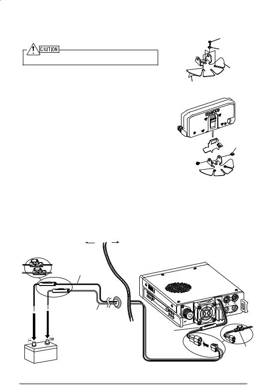
νPower Cable Connection
Be sure to use a 12 V vehicle battery that has sufficient current capacity. If the current to the transceiver is insufficient, the display may darken during transmission or the transmit output power may drop excessively. Never connect the transceiver to a 24 V battery.
Engine compartment |
Passenger compartment |
Fuse holder (E type)
Black (—) cable
Fuse holder |
|
|
|
(K, M4 types) |
Red (+) |
|
|
|
cable |
|
|
|
Rubber grommet |
Fuse holder |
|
|
(K, M4 types) |
||
12 V vehicle |
|||
Fuse holder |
|||
battery |
|
||
|
|
(E type) |
|
DC power cable

Note: If you use the transceiver for a long period when the vehicle battery is not fully charged or when the engine is OFF, the battery may become discharged and will not have sufficient reserves to start the vehicle. Avoid using the transceiver under these conditions.
1Route the DC power cable supplied with the transceiver directly to the vehicle’s battery terminals using the shortest path from the transceiver.
•When using a noise filter, it should be installed with an insulator to prevent it from touching metal on the vehicle.
•We do not recommend using a cigarette lighter socket as some cigarette lighter sockets introduce an unacceptable voltage drop.
•If the power cable must be routed through a hole in the vehicle chassis or body, for example in the fire wall at the front of the passenger compartment, use a rubber grommet to protect the cable from abrasion. Dismantle the fuse holder to pass the cable through the fire wall.
•The entire length of the cable must be dressed so it is isolated from heat, moisture, and the engine secondary (high voltage) ignition system/ cables.
2After the cable is in place, wind heat-resistant tape around the fuse holder to protect it from moisture. Tie down the full run of cable.
3To prevent the risk of short circuits, disconnect other wiring from the negative (–) battery terminal before connecting the transceiver.
Fixed Station
νOperation Panel Installation
1Attach the panel holder to the base stand using the 2 supplied SEMS screws.
2Attach the operation panel to the panel holder so that it locks in place.
Operation panel
SEMS screw (M4 x 10 mm)
Panel holder
Base stand
ν Power Cable Connection
In order to use this transceiver for fixed station operation, you will need a separate 13.8 V DC power supply that must be purchased separately. The recommended current capacity of the power supply is 13 A.
Note: Do not plug the DC power supply into an AC outlet until you make all connections.
Fuse holder (E type)
Black (—) cable
Fuse holder (K, M4 types)
Red (+) |
|
cable |
Fuse holder |
|
(K, M4 types) |
Fuse holder (E type)
DC power cable
Regulated DC power supply
1Ensure that the transceiver and DC power supply are both OFF.
2Connect the DC power cable to the regulated DC power supply and ensure that the polarities are correct (Red: positive, Black: negative).
•Use the supplied DC power cable to connect the transceiver to a regulated power supply. Do not directly connect the transceiver to an AC outlet.
•Do not substitute the cable with smaller gauge wires.
3Connect the DC power cable to the transceiver.
•Press the connectors firmly together until the locking tab clicks.
Note: For your transceiver to fully exhibit its performance capabilities, we recommend using an optional PS-33 (20.5 A, 25% duty cycle) power supply.

Replacing Fuses
If the fuse blows, determine the cause, then correct the problem. After the problem is resolved, replace the fuse. If newly installed fuses continue to blow, disconnect the power cable and contact your authorized Kenwood dealer or an authorized Kenwood service center for assistance.
|
|
|
Fuse Location |
Fuse Current Rating |
|
|
|
|
|
|
|
Transceiver |
15 A |
||||
(located on the DC connector) |
|||||
|
|||||
|
|
|
|
|
|
Supplied DC power cable |
20 A |
||||
|
|
|
|
|
|
|
|
|
|
|
|
|
|
|
|
|
|
|
|
|
|
|
|
|
|
|
|
|
|
Only use fuses of the specified type and rating; otherwise the transceiver could be damaged.
Fuse holder (E type) Fuse holder (K, M4 types)
Fuse |
Fuse holder |
Fuse |
|
||
|
|
|
Fuse holder |
|
|
Operation Panel and Microphone Connection
Plug the microphone plug to the MIC jack, then connect the Operation panel to the TX/ RX unit with the supplied cable.
•Attach the microphone hanger to an appropriate position using the screws included in the screw set.
Microphone |
TX/ RX unit |
MIC jack
Line filter
Modular plug cable
Line filter
Installing the Line Filter
Install the line filter approximately 3 cm from the connector.
Panel jack
Operation panel

Antenna Connection
Before operating, you must first install an efficient, well-tuned antenna. The success of your installation will depend largely on the type of antenna and its correct installation. The transceiver can give excellent results if the antenna system and its installation are given careful attention.
Use a low-loss coaxial feed line that also has a characteristic impedance of
50 Ω, to match the transceiver input impedance. Coupling the antenna to the transceiver via feed lines having an impedance other than 50 Ω reduces the efficiency of the antenna system and can cause interference to nearby broadcast television receivers, radio receivers, and other electronic equipment.
υTransmitting without first connecting an antenna or other matched load may damage the transceiver. Always connect the antenna to the transceiver before transmitting.
υAll fixed stations should be equipped with a lightning arrester to reduce the risk of fire, electric shock, and/or transceiver damage.
Antenna terminal |
|
Feed line connector |
To antenna |
Accessory Connections
νExternal Speakers
If you plan to use external speakers, choose speakers with an impedance of
8 Ω. The external speaker jacks accept a 3.5 mm (1/8”) mono (2-conductor) plug. We recommend using SP-50B speakers.
There are 2 speaker jacks on the rear of the transceiver: SP 1 and SP 2.
SP 1 jack
External speakers (SP-50B)
SP 2 jack

GETTING ACQUAINTED
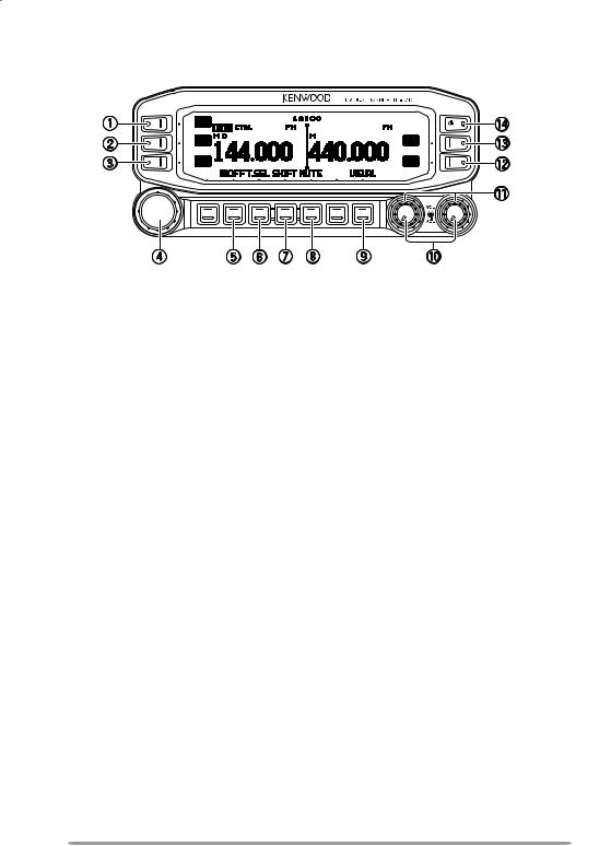
OPERATION Panel (FRONT) ν IN NORMAL mode
q CALL
Press [CALL] to select the Call channel. Press [CALL] (1s) to start Call scan.
w VFO
Press [VFO] to enter VFO mode , then rotate the Tuning control to select an operating frequency.
Press [VFO] (1s) to start VFO scan.
e MR
Press [MR] to enter Memory Channel mode, then rotate the Tuning control to select a Memory channel.
Press [MR] (1s) to start Memory scan.
rTuning Control
Rotate to select an operating frequency or Memory channel, change the scan direction, etc.
Press the Tuning control to enter MHz mode (while in VFO or Call mode) or to toggle the display between the channel name and frequency (while in Memory Channel mode).
Press Tuning control (1s) to start MHz scan or Group scan.
tKEY
Press [KEY] to turn the APRS key function ON and OFF.
yF
Press [F] to enter Function mode.
Press [F] (1s) to turn the transceiver key lock function ON and OFF.

uTONE
Press [TONE] to turn the Tone function ON.
Each time you press [TONE] to toggle the functions as follows: Tone ON >> CTCSS ON >> DCS ON >> OFF.
iREV
Press [REV] to turn the Reverse function ON or OFF.
Press [REV] (1s) to turn the Automatic Simplex Checker ON.
oLOW
Press [LOW] to toggle the transmit output power as follows: High Power (K, E types only) –> Middle Power –> Low Power.
!0PF1
Press [PF1] to activate its programmable function. The default function is “Frequency Band Select”.
!1PF2
Press [PF2] to activate its programmable function. The default function is “Operation Band Select”.
!2BAND SEL (VOL) Control
Rotate the [BAND SEL] control to adjust the speaker volume.
Press the left [BAND SEL] to select the A band. Press the right [BAND SEL] to select the B band.
Press [BAND SEL] (1s) to toggle between single and dual-band mode.
!3SQL Control
Rotate the [SQL] control to adjust the squelch level. Clockwise opens the squelch and counterclockwise tightens the squelch.
!4TNC
Press [TNC] to turn built-in TNC ON and the APRS (or NAVITRA) mode ON. Each time you press [TNC], the mode toggles as follows: APRS (or NAVITRA) mode ON >> PACKET mode ON >> TNC OFF.
•When the built-in TNC turns on, “OPENING TNC” appears on the display.
•When “OPENING TNC” appears on the display, the mode cannot be changed.
!5PM
Press [PM] to enters the PM (Programmable Memory) channel selection mode.
!6
Press  ] to turn the transceiver power ON and OFF.
ν IN Function mode
qC.IN
Press [C.IN] to store the current operating frequency to the Call channel.
wM>V
Press [M>V] to copy the current Memory channel or Call channel to the VFO (memory shift).
eM.IN
Select a Memory channel, then press [M.IN] to store the current operating frequency in the Memory channel.
r Tuning Control
Press the Tuning control to enter Menu mode.
tF OFF
Press [F OFF] to return Normal mode.
y T.SEL
While Tone, CTCSS, or DCS is ON, press [T.SEL] to enter CTCSS or DCS setup mode.
u SHIFT
Press [SHIFT] to enter Offset Direction selection mode. Each time you press [SHIFT], the offset direction toggles as follows:
plus (+) direction –> minus (–) direction –> –7.6 MHz (E type only) –> OFF.
iMUTE
Press [MUTE] to turn the Mute function ON or OFF.
oVISUAL
Press [VISUAL] to turn the Visual Scan function ON and OFF.
!0BAND SEL (VOL) Control
Rotate the [BAND SEL] control to adjust the speaker volume. Press [BAND SEL] to select a frequency band.
10
 Loading...