


tek.com/keithley
Model DMM6500
6½-Digit Bench/System Multimeter
User’s Manual
DMM6500-900-01 Rev. A / April 2018
*PDMM6500-900-01A*
DMM6500-900-01A
DMM6500
6½ Digit Multimeter
User's Manual
© 2018, Keithley Instruments, LLC
Cleveland, Ohio, U.S.A. All rights reserved.
Any unauthorized reproduction, photocopy, or use of the information herein, in whole or in part, without the prior written approval of Keithley Instruments, LLC, is strictly prohibited.
These are the original instructions in English.
TSP®, TSP-Link®, and TSP-Net® are trademarks of Keithley Instruments, LLC. All Keithley Instruments product names are trademarks or registered trademarks of Keithley Instruments, LLC. Other brand names are trademarks or registered trademarks of their respective holders.
The Lua 5.0 software and associated documentation files are copyright © 1994 - 2015, Lua.org, PUC-Rio. You can access terms of license for the Lua software and associated documentation at the Lua licensing site (http://www.lua.org/license.html).
Microsoft, Visual C++, Excel, and Windows are either registered trademarks or trademarks of Microsoft Corporation in the United States and/or other countries.
Document number: DMM6500-900-01Rev. A / April 2018

Safety precautions
The following safety precautions should be observed before using this product and any associated instrumentation. Although some instruments and accessories would normally be used with nonhazardous voltages, there are situations where hazardous conditions may be present.
This product is intended for use by personnel who recognize shock hazards and are familiar with the safety precautions required to avoid possible injury. Read and follow all installation, operation, and maintenance information carefully before using the product. Refer to the user documentation for complete product specifications.
If the product is used in a manner not specified, the protection provided by the product warranty may be impaired.
The types of product users are:
Responsible body is the individual or group responsible for the use and maintenance of equipment, for ensuring that the equipment is operated within its specifications and operating limits, and for ensuring that operators are adequately trained.
Operators use the product for its intended function. They must be trained in electrical safety procedures and proper use of the instrument. They must be protected from electric shock and contact with hazardous live circuits.
Maintenance personnel perform routine procedures on the product to keep it operating properly, for example, setting the line voltage or replacing consumable materials. Maintenance procedures are described in the user documentation. The procedures explicitly state if the operator may perform them. Otherwise, they should be performed only by service personnel.
Service personnel are trained to work on live circuits, perform safe installations, and repair products. Only properly trained service personnel may perform installation and service procedures.
Keithley products are designed for use with electrical signals that are measurement, control, and data I/O connections, with low transient overvoltages, and must not be directly connected to mains voltage or to voltage sources with high transient overvoltages. Measurement Category II (as referenced in IEC 60664) connections require protection for high transient overvoltages often associated with local AC mains connections. Certain Keithley measuring instruments may be connected to mains. These instruments will be marked as category II or higher.
Unless explicitly allowed in the specifications, operating manual, and instrument labels, do not connect any instrument to mains.
Exercise extreme caution when a shock hazard is present. Lethal voltage may be present on cable connector jacks or test fixtures. The American National Standards Institute (ANSI) states that a shock hazard exists when voltage levels greater than 30 V RMS, 42.4 V peak, or 60 VDC are present. A good safety practice is to expect that hazardous voltage is present in any unknown circuit before measuring.
Operators of this product must be protected from electric shock at all times. The responsible body must ensure that operators are prevented access and/or insulated from every connection point. In some cases, connections must be exposed to potential human contact. Product operators in these circumstances must be trained to protect themselves from the risk of electric shock. If the circuit is capable of operating at or above 1000 V, no conductive part of the circuit may be exposed.
Do not connect switching cards directly to unlimited power circuits. They are intended to be used with impedance-limited sources. NEVER connect switching cards directly to AC mains. When connecting sources to switching cards, install protective devices to limit fault current and voltage to the card.
Before operating an instrument, ensure that the line cord is connected to a properly-grounded power receptacle. Inspect the connecting cables, test leads, and jumpers for possible wear, cracks, or breaks before each use.
When installing equipment where access to the main power cord is restricted, such as rack mounting, a separate main input power disconnect device must be provided in close proximity to the equipment and within easy reach of the operator.
For maximum safety, do not touch the product, test cables, or any other instruments while power is applied to the circuit under test. ALWAYS remove power from the entire test system and discharge any capacitors before: connecting or disconnecting cables or jumpers, installing or removing switching cards, or making internal changes, such as installing or removing jumpers.
Do not touch any object that could provide a current path to the common side of the circuit under test or power line (earth) ground. Always make measurements with dry hands while standing on a dry, insulated surface capable of withstanding the voltage being measured.
For safety, instruments and accessories must be used in accordance with the operating instructions. If the instruments or accessories are used in a manner not specified in the operating instructions, the protection provided by the equipment may be impaired.
Do not exceed the maximum signal levels of the instruments and accessories. Maximum signal levels are defined in the specifications and operating information and shown on the instrument panels, test fixture panels, and switching cards.
When fuses are used in a product, replace with the same type and rating for continued protection against fire hazard.
Chassis connections must only be used as shield connections for measuring circuits, NOT as protective earth (safety ground) connections.
If you are using a test fixture, keep the lid closed while power is applied to the device under test. Safe operation requires the use of a lid interlock.
If a  screw is present, connect it to protective earth (safety ground) using the wire recommended in the user documentation.
The  symbol on an instrument means caution, risk of hazard. The user must refer to the operating instructions located in the user documentation in all cases where the symbol is marked on the instrument.
The  symbol on an instrument means warning, risk of electric shock. Use standard safety precautions to avoid personal contact with these voltages.
The  symbol on an instrument shows that the surface may be hot. Avoid personal contact to prevent burns. The
  symbol indicates a connection terminal to the equipment frame.
If this  symbol is on a product, it indicates that mercury is present in the display lamp. Please note that the lamp must be properly disposed of according to federal, state, and local laws.
The WARNING heading in the user documentation explains hazards that might result in personal injury or death. Always read the associated information very carefully before performing the indicated procedure.
The CAUTION heading in the user documentation explains hazards that could damage the instrument. Such damage may invalidate the warranty.
The CAUTION heading with the  symbol in the user documentation explains hazards that could result in moderate or minor injury or damage the instrument. Always read the associated information very carefully before performing the indicated procedure. Damage to the instrument may invalidate the warranty.
Instrumentation and accessories shall not be connected to humans.
Before performing any maintenance, disconnect the line cord and all test cables.
To maintain protection from electric shock and fire, replacement components in mains circuits — including the power transformer, test leads, and input jacks — must be purchased from Keithley. Standard fuses with applicable national safety approvals may be used if the rating and type are the same. The detachable mains power cord provided with the instrument may only be replaced with a similarly rated power cord. Other components that are not safety-related may be purchased from other suppliers as long as they are equivalent to the original component (note that selected parts should be purchased only through Keithley to maintain accuracy and functionality of the product). If you are unsure about the applicability of a replacement component, call a Keithley office for information.
Unless otherwise noted in product-specific literature, Keithley instruments are designed to operate indoors only, in the following environment: Altitude at or below 2,000 m (6,562 ft); temperature 0 °C to 50 °C (32 °F to 122 °F); and pollution degree 1 or 2.
To clean an instrument, use a cloth dampened with deionized water or mild, water-based cleaner. Clean the exterior of the instrument only. Do not apply cleaner directly to the instrument or allow liquids to enter or spill on the instrument. Products that consist of a circuit board with no case or chassis (e.g., a data acquisition board for installation into a computer) should never require cleaning if handled according to instructions. If the board becomes contaminated and operation is affected, the board should be returned to the factory for proper cleaning/servicing.
Safety precaution revision as of June 2017.
|
Table of contents |
Introduction............................................................................................................... |
1-1 |
Welcome .............................................................................................................................. |
1-1 |
Introduction to this manual................................................................................................... |
1-1 |
Contact information .............................................................................................................. |
1-2 |
Extended warranty ............................................................................................................... |
1-2 |
Documentation set ............................................................................................................... |
1-2 |
Organization of manual sections.......................................................................................... |
1-2 |
Application examples ........................................................................................................... |
1-3 |
Front-panel overview................................................................................................ |
2-1 |
Front-panel overview............................................................................................................ |
2-1 |
TRIGGER key ........................................................................................................................... |
2-2 |
Instrument power ................................................................................................................. |
2-3 |
Connect the power cord ............................................................................................................ |
2-4 |
Turn the DMM6500 on or off ..................................................................................................... |
2-4 |
Touchscreen display ............................................................................................................ |
2-5 |
Select items on the touchscreen ............................................................................................... |
2-5 |
Scroll bars ................................................................................................................................. |
2-5 |
Enter information....................................................................................................................... |
2-6 |
Adjust the backlight brightness and dimmer.............................................................................. |
2-6 |
Review event messages ........................................................................................................... |
2-7 |
Interactive swipe screens..................................................................................................... |
2-7 |
Swipe screen heading bar......................................................................................................... |
2-7 |
FUNCTIONS swipe screen ....................................................................................................... |
2-9 |
SETTINGS swipe screen .......................................................................................................... |
2-9 |
STATISTICS swipe screen...................................................................................................... |
2-10 |
SECONDARY swipe screen.................................................................................................... |
2-11 |
USER swipe screen ................................................................................................................ |
2-12 |
GRAPH swipe screen ............................................................................................................. |
2-12 |
SCAN swipe screen ................................................................................................................ |
2-13 |
Menu overview ................................................................................................................... |
2-14 |
Channel menu......................................................................................................................... |
2-15 |
Measure Menu ........................................................................................................................ |
2-15 |
Views menu............................................................................................................................. |
2-16 |
Trigger menu........................................................................................................................... |
2-16 |
Scripts menu ........................................................................................................................... |
2-17 |
System menu .......................................................................................................................... |
2-17 |
Using a remote interface .......................................................................................... |
3-1 |
Remote communications interfaces..................................................................................... |
3-1 |
Supported remote interfaces................................................................................................ |
3-2 |
LAN communications ........................................................................................................... |
3-2 |
Set up LAN communications on the instrument ........................................................................ |
3-3 |
Set up LAN communications on the computer .......................................................................... |
3-4 |

Table of contents DMM6500 6½ Digit Multimeter User's Manual
USB communications........................................................................................................... |
3-5 |
Connect a computer to the DMM6500 using USB..................................................................... |
3-5 |
Communicate with the instrument............................................................................................. |
3-6 |
GPIB communications.......................................................................................................... |
3-9 |
Install the KTTI-GPIB accessory card ....................................................................................... |
3-9 |
Set the GPIB address ............................................................................................................. |
3-12 |
RS-232 ............................................................................................................................... |
3-12 |
Install the KTTI-RS232 accessory card................................................................................... |
3-12 |
TSP-Link ............................................................................................................................ |
3-14 |
Install the KTTI-TSP accessory card....................................................................................... |
3-14 |
Using the web interface...................................................................................................... |
3-15 |
Connect to the instrument web interface................................................................................. |
3-15 |
LAN troubleshooting suggestions............................................................................................ |
3-16 |
Web interface Home page....................................................................................................... |
3-17 |
Identify the instrument............................................................................................................. |
3-17 |
Determining the command set you will use ....................................................................... |
3-18 |
Making basic front-panel measurements................................................................ |
4-1 |
Introduction .......................................................................................................................... |
4-1 |
Equipment required for this example ................................................................................... |
4-1 |
Device connections .............................................................................................................. |
4-2 |
Basic front-panel measurements ......................................................................................... |
4-3 |
Measuring DC voltage with high accuracy.............................................................. |
5-1 |
Introduction .......................................................................................................................... |
5-1 |
Equipment required.............................................................................................................. |
5-1 |
Device connections .............................................................................................................. |
5-2 |
Measuring DCV with high accuracy..................................................................................... |
5-3 |
Using the front panel ................................................................................................................. |
5-4 |
Using SCPI commands ............................................................................................................. |
5-5 |
Using TSP commands .............................................................................................................. |
5-5 |
Test results................................................................................................................................ |
5-7 |
Measuring 4-wire resistance with offset compensation......................................... |
6-1 |
Introduction .......................................................................................................................... |
6-1 |
Equipment required.............................................................................................................. |
6-1 |
Device connections .............................................................................................................. |
6-2 |
Measuring 4-wire resistance with offset compensation ....................................................... |
6-3 |
Using the front panel ................................................................................................................. |
6-4 |
Using SCPI commands ............................................................................................................. |
6-4 |
Using TSP commands .............................................................................................................. |
6-5 |
Test results................................................................................................................................ |
6-6 |
DMM6500 6½ Digit Multimeter User's Manual |
Table of contents |
Scanning temperature at a set time interval ........................................................... |
7-1 |
Introduction .......................................................................................................................... |
7-1 |
Equipment required.............................................................................................................. |
7-1 |
Device connections .............................................................................................................. |
7-2 |
Sample temperatures at a specific time interval .................................................................. |
7-4 |
Using the front panel ................................................................................................................. |
7-4 |
Using SCPI commands ............................................................................................................. |
7-5 |
Using TSP................................................................................................................................. |
7-6 |
Test results................................................................................................................................ |
7-7 |
Grading and binning resistors................................................................................. |
8-1 |
Introduction .......................................................................................................................... |
8-1 |
Equipment required.............................................................................................................. |
8-1 |
Device connections .............................................................................................................. |
8-2 |
Resistor grading and binning test ........................................................................................ |
8-3 |
Trigger model template: grade and binning test........................................................................ |
8-4 |
Using SCPI commands ............................................................................................................. |
8-5 |
Using TSP commands .............................................................................................................. |
8-6 |
Measuring power using digitizing and TSP-Link.................................................... |
9-1 |
Introduction .......................................................................................................................... |
9-1 |
Equipment required.............................................................................................................. |
9-2 |
Device connections .............................................................................................................. |
9-2 |
Measuring power using digitizing and TSP-Link.................................................................. |
9-4 |
Using SCPI commands ............................................................................................................. |
9-4 |
Setting up the nodes for TSP code ........................................................................................... |
9-4 |
Using TSP commands .............................................................................................................. |
9-5 |
Results ...................................................................................................................................... |
9-7 |
Troubleshooting FAQs ........................................................................................... |
10-1 |
About this section............................................................................................................... |
10-1 |
Where can I find updated drivers? ..................................................................................... |
10-1 |
Is there any software to help me get started...................................................................... |
10-2 |
How do I upgrade the firmware?........................................................................................ |
10-2 |
Why can't the DMM6500 read my USB flash drive?.......................................................... |
10-3 |
How do I change the command set? ................................................................................. |
10-3 |
How do I save the present state of the instrument? .......................................................... |
10-4 |
Why did my settings change? ............................................................................................ |
10-5 |
What is the ethernet port number? .................................................................................... |
10-5 |
Table of contents |
DMM6500 6½ Digit Multimeter User's Manual |
Next steps ............................................................................................................... |
11-1 |
Additional DMM6500 information....................................................................................... |
11-1 |
Index ........................................................................................................................... |
I-1 |
Section 1
Introduction
In this section:
Welcome .................................................................................. |
1-1 |
Introduction to this manual ....................................................... |
1-1 |
Contact information .................................................................. |
1-2 |
Extended warranty ................................................................... |
1-2 |
Documentation set ................................................................... |
1-2 |
Organization of manual sections .............................................. |
1-2 |
Application examples ............................................................... |
1-3 |
Welcome
Thank you for choosing a Keithley Instruments product. The DMM6500 is a 6½ digit bench/system digital multimeter with scanning that expands standard DMM functions with high-speed digitizing and large graphical color touchscreen display. This DMM offers a broad range of measurement capabilities, including 15 measurement functions. In addition to industry-leading DC accuracies, functions such as capacitance, 10 A current, and 16-bit current and voltage digitizing are included. Tying all these features together is a large 5-inch color touchscreen display that brings users an unprecedented combination of data visualization and interaction, enabling users to gain deeper insight into their measurements.
The DMM6500 provides superior measurement accuracy and the speed necessary for a broad range of applications, from system applications and production testing to benchtop applications. The DMM6500 meets application requirements for production engineers, research and development engineers, test engineers, and scientists.
Introduction to this manual
This manual provides detailed applications to help you achieve success with your Keithley Instruments DMM6500. In addition, this manual provides information about the basics of the front panel to familiarize you with the instrument.
This manual presents an overview of each application, followed by instructions to complete the application using the front panel, SCPI code, TSP code, or Keithley KickStart Startup Software.
More information about the commands that are used in these applications is available. Refer to the SCPI and TSP command reference sections of the Model DMM6500 Reference Manual. This manual is on tek.com/keithley.
Section 1: Introduction |
DMM6500 6½ Digit Multimeter User's Manual |
Contact information
If you have any questions after you review the information in this documentation, please contact your local Keithley Instruments office, sales partner, or distributor. You can also call the corporate headquarters of Keithley Instruments (toll-free inside the U.S. and Canada only) at 1-800-935-5595, or from outside the U.S. at +1-440-248-0400. For worldwide contact numbers, visit tek.com/keithley.
Extended warranty
Additional years of warranty coverage are available on many products. These valuable contracts protect you from unbudgeted service expenses and provide additional years of protection at a fraction of the price of a repair. Extended warranties are available on new and existing products. Contact your local Keithley Instruments office, sales partner, or distributor for details.
Documentation set
The DMM6500 documentation is supported by the following technical/product information documentation.
•Quick Start Guide: Provides unpacking instructions, describes basic connections, reviews basic operation information, and provides a quick test procedure to ensure the instrument is operational.
•User’s Manual: Provides application examples that you can use as a starting point to create your own applications.
•Reference Manual: Includes advanced operation topics, maintenance information, troubleshooting procedures, and in-depth descriptions of programming commands.
•Accessories information: Documentation for accessories that are available for the DMM6500.
For the latest drivers and additional support information, see tek.com/keithley.
Organization of manual sections
This manual is organized into the following sections:
•Using the front-panel interface: (on page 2-1) Describes the basics of using the front-panel interface.
•Using a remote interface: (on page 3-1) Describes the basics of remote communications and using the instrument web interface.
•Application examples (see below): Provides detailed examples of how to use the DMM6500 in some typical situations.
•Troubleshooting FAQs: (on page 10-1) Provides answers to frequently asked questions to help you troubleshoot common problems encountered with the DMM6500.
•Next steps: (on page 11-1) Provides information about additional resources that can help you use the DMM6500.
The PDF version of this manual contains bookmarks for each section. The manual sections are also listed in the Table of Contents at the beginning of this manual.
For more information about bookmarks, see Adobe® Acrobat® or Reader® help.
1-2 |
DMM6500-900-01Rev. A / April 2018 |
DMM6500 6½ Digit Multimeter User's Manual |
Section 1: Introduction |
Application examples
This manual provides application examples that show you how to perform tests from the front panel and over a remote interface. The applications include:
•Making basic front-panel measurements: (on page 4-1) Shows the basic measure functionality using a single DMM6500 and a two-terminal device under test.
•Measuring DC voltage with high accuracy: (on page 5-1) Shows how to use a DMM6500 to make a high-accuracy DC voltage measurement.
•Measuring 4-wire resistance with offset compensation: (on page 6-1) Shows how to use the DMM6500 to accurately measure a resistance device.
•Scanning temperature at a set time interval: (on page 7-1) Shows how to use the DMM6500 to log temperature measurement data every minute over a 24-hour period.
•Grading and binning resistors: (on page 8-1) Shows how to use the DMM6500 to perform benchtop binning operations using the trigger model and digital I/O to control external component-handling devices.
•Measuring power using digitizing and TSP-Link: (on page 9-1) Shows how to configure two DMM6500s to measure the power consumed by a Bluetooth low energy device using TSP-Link.
DMM6500-900-01Rev. A / April 2018 |
1-3 |
Section 2
Front-panel overview
In this section:
Front-panel overview................................................................ |
2-1 |
Instrument power...................................................................... |
2-3 |
Touchscreen display................................................................. |
2-5 |
Interactive swipe screens ......................................................... |
2-7 |
Menu overview ....................................................................... |
2-14 |
Front-panel overview
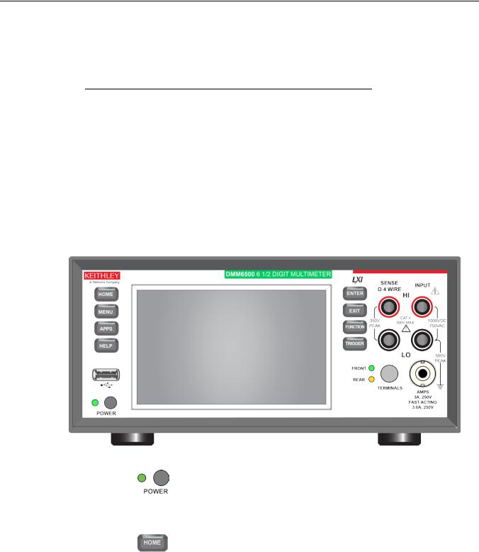
The front panel of the DMM6500 is shown below. Descriptions of the controls on the front panel follow the figure.
Figure 1: DMM6500 front panel
POWER switch
HOME key
Turns the instrument on or off. To turn the instrument on, press and hold the power switch. To turn it off, press and hold the power switch again. The LED is green when the instrument is on and the LED is amber when turned off.
Returns the display to the Home screen.

Section 2: Front-panel overview |
DMM6500 6½ Digit Multimeter User's Manual |
MENU key
APPS key
HELP key
USB port
Touchscreen
ENTER key
EXIT key
TRIGGER key
TRIGGER key
Opens the main menu. Press the icons on the main menu to open channel, measure, views, trigger, scripts, and system screens. For details, refer to Menu overview (on page 2-14).
Opens a menu of of preconfigured TSP scripts with a graphical user interface.
Opens help for the area or item that is selected on the display. If there is no selection when you press the HELP key, it displays overview information for the screen you are viewing.
Saves reading buffer data and screen snapshots to a USB flash drive. You can also store and retrieve scripts to and from a USB flash drive. The flash drive must be formatted as a FAT or FAT32 drive.
The DMM6500 has a high-resolution, five-inch color touchscreen display. The touchscreen accesses swipe screens and menu options. You can access additional interactive screens by pressing the front-panel MENU, APPS, and FUNCTION keys. Refer to Touchscreen display (on page 2-5) for details.
Selects the highlighted choice or allows you to edit the selected field.
Returns to the previous screen or closes a dialog box. For example, press the EXIT key when the main menu is displayed to return to the Home screen. When you are viewing a subscreen (for example, the Event Log screen), press the EXIT key to return to the main menu screen.
Accesses trigger-related settings and operations. The action of the TRIGGER key depends on the instrument state. For details, see "Switching between measurement methods" in the Model DMM6500 Reference Manual.
2-2 |
DMM6500-900-01Rev. A / April 2018 |
DMM6500 6½ Digit Multimeter User's Manual |
Section 2: Front-panel overview |
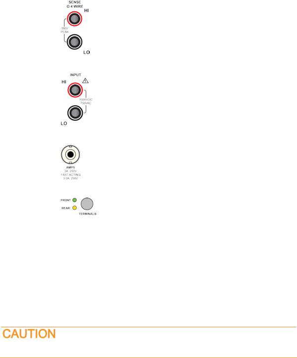
SENSE terminals
INPUT terminals
AMPS
TERMINALS switch
Use the SENSE HI and SENSE LO terminals and the INPUT terminals with the 4-wire resistance, 3-wire and 4-wire RTD temperature, and DC voltage ratio functions.
Use the INPUT HI and INPUT LO terminals for all measurements except current.
Use the AMPS connection with the INPUT LO terminal to measure ≤3A DC or ACRMS current.
Activates the terminals on the front or rear panel. Selecting the rear panel provides the proper connections to an inserted *** Set CardType variable***. When the front-panel terminals are active, the green LED is visible. When the rear-panel terminals are active, the amber LED is visible.
Instrument power
Follow the steps below to connect the DMM6500 to line power and turn on the instrument. The DMM6500 operates from a line voltage of 100 V to 240 V at a frequency of 50 Hz, 60 Hz, or 400 Hz. It automatically senses line frequency. Make sure the operating voltage in your area is compatible.
The fuse is set to the expected voltage at the factory. Make sure that the correct line voltage is displayed on the power module. See Line voltage verification for more information.
You must turn on the DMM6500 and allow it to warm up for at least 30 minutes to achieve rated accuracies.
Operating the instrument on an incorrect line voltage may cause damage to the instrument, possibly voiding the warranty.
DMM6500-900-01Rev. A / April 2018 |
2-3 |
Section 2: Front-panel overview |
DMM6500 6½ Digit Multimeter User's Manual |
The power cord supplied with the DMM6500 contains a separate protective earth (safety ground) wire for use with grounded outlets. When proper connections are made, the instrument chassis is connected to power-line ground through the ground wire in the power cord. In the event of a failure, not using a properly grounded protective earth and grounded outlet may result in personal injury or death due to electric shock.
Do not replace detachable mains supply cords with inadequately rated cords. Failure to use properly rated cords may result in personal injury or death due to electric shock.
Connect the power cord
When you connect the power cord, the instrument may power on, depending on the state of the frontpanel POWER switch when the power cord was removed.
To connect the power cord:
1.Connect the female end of the supplied power cord to the AC receptacle on the rear panel.
2.Connect the male end of the power cord to a grounded AC outlet.
Turn the DMM6500 on or off
Hazardous voltages may be present on all output and guard terminals. To prevent electrical shock that could cause injury or death, remove power from the instrument or test system and discharge any energy storage components (for example, capacitors or cables) before changing any connections that might allow contact with an uninsulated conductor.
On some sensitive or easily damaged devices under test (DUTs), the instrument power-up or powerdown sequence can apply transient signals to the DUT that may affect or damage it.
When testing this type of DUT, do not make final connections to it until the instrument has completed its power-up sequence and is in a known operating state. Disconnect it from the instrument before turning the instrument off.
To prevent any human contact with a live conductor, connections to the DUT must be fully insulated and the final connections to the DUT must only use safety-rated safety jack socket connectors that do not allow bodily contact.
To turn a DMM6500 on:
1.Disconnect any devices under test (DUTs) from the DMM6500.
2.Press and hold the front-panel POWER switch to place it in the on position.
The instrument displays a status bar as the instrument powers on. The Home screen is displayed when power on is complete.
To turn a DMM6500 off:
1. Press and hold the front-panel POWER switch to place it in the off position.
2-4 |
DMM6500-900-01Rev. A / April 2018 |
DMM6500 6½ Digit Multimeter User's Manual |
Section 2: Front-panel overview |
Touchscreen display
The touchscreen display gives you quick front-panel access to measure settings, system configuration, instrument and test status, reading buffer information, and other instrument functionality. The display has multiple swipe screens that you can access by swiping the front panel. You can access additional interactive screens by pressing the front-panel MENU, APPS, and FUNCTION keys.
Do not use sharp metal objects, such as tweezers or screwdrivers, or pointed objects, such as pens or pencils, to touch the touchscreen. It is strongly recommended that you use only fingers to operate the instrument. Use of clean-room gloves to operate the touchscreen is supported.
Select items on the touchscreen
To select an item on the displayed screen:
•Press the corresponding icon on the screen.
The following topics describe the DMM6500 touchscreen in more detail.
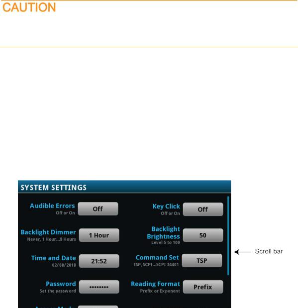
Scroll bars
Some of the interactive screens have additional options that are only visible when you scroll down the screen. A scroll indicator on the right side of the touchscreen identifies these screens. Swipe the screen up or down to view the additional options.
The figure below shows a screen with a scroll bar.
Figure 2: Scroll bar
DMM6500-900-01Rev. A / April 2018 |
2-5 |
Section 2: Front-panel overview |
DMM6500 6½ Digit Multimeter User's Manual |
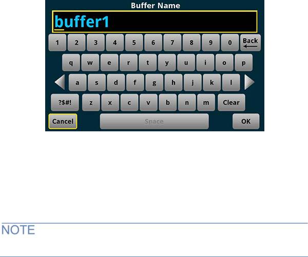
Enter information
Some of the menu options open a keypad or keyboard that you can use to enter information. For example, if you are creating a new reading buffer from the front panel, you see the keypad shown in the following figure.
Figure 3: DMM6500 front-panel keyboard for information entry
You can enter information by touching the screen to select characters and options from the keypad or keyboard. You can move the cursor in the entry box by touching the screen. The cursor is moved to the spot in the entry box where you touched the screen.
Adjust the backlight brightness and dimmer
You can adjust the brightness of the DMM6500 touchscreen display and buttons from the front panel or over a remote interface. You can also set the backlight to dim after a specified time has passed with no front-panel activity (available from the front-panel display only). The backlight settings set through the front-panel display are saved through a reset or power cycle.
Screen life is affected by how long the screen is on at full brightness. The higher the brightness setting and the longer the screen is bright, the shorter the screen life.
To adjust the backlight brightness from the front panel:
1.Press the MENU key.
2.Under System, select Settings.
3.Select the Backlight Brightness. The Backlight Brightness dialog box opens.
4.Drag the adjustment to set the backlight.
5.Select OK.
2-6 |
DMM6500-900-01Rev. A / April 2018 |
DMM6500 6½ Digit Multimeter User's Manual |
Section 2: Front-panel overview |
To set the backlight dimmer from the front panel:
1.Press the MENU key.
2.Under System, select Settings.
3.Select Backlight Dimmer. The Backlight Dimmer dialog box opens.
4.Select a dimmer setting.
Review event messages
During operation and programming, front-panel messages may be briefly displayed. Messages are either information, warning, or error notifications. For information on event messages, refer to "Using the event log" in the Model DMM6500 Reference Manual.
Figure 4: Example front-panel event message
Interactive swipe screens
The DMM6500 touchscreen display has multiple screens that you can access by swiping left or right on the lower half of the display. The options available in the swipe screens are described in the following topics.
Swipe screen heading bar
The heading bar of the swipe screen contains the following options.
Figure 5: DMM6500 swipe screens, maximized and minimized
DMM6500-900-01Rev. A / April 2018 |
2-7 |

Section 2: Front-panel overview |
DMM6500 6½ Digit Multimeter User's Manual |
|||
|
|
|
|
|
|
# |
Screen element |
Description |
|
|
|
|
|
|
|
1 |
Minimize indicator |
You can swipe down to minimize the swipe screens. |
|
|
|
|
|
|
|
2 |
Swipe screen indicator |
Each circle represents one swipe screen. As you swipe right or left, a different |
|
|
|
|
circle changes color, indicating where you are in the screen sequence. Select a |
|
|
|
|
circle to move the swipe screen without swiping. |
|
|
|
|
|
|
|
3 |
Calculations shortcut |
Select to open the CALCULATION SETTINGS menu. Only available when |
|
|
|
|
TERMINALS is set to FRONT. |
|
|
|
|
|
|
|
4 |
Measure Settings |
Select to open the MEASURE SETTINGS menu for the selected function. Only |
|
|
|
shortcut |
available when TERMINALS is set to FRONT. |
|
|
|
|
|
|
|
5 |
Restore indicator |
Indicates that you can swipe up to display the swipe screen. |
|
|
|
|
|
|
|
6 |
Graph shortcut |
Select to open the Graph screen. |
|
|
|
|
|
|
|
|
Channel Settings |
Not shown. Select to open the CHANNEL SETTINGS screen. |
|
|
|
shortcut |
|
|
|
|
|
|
|
|
|
Scan shortcut |
Not shown. Select to open the SCAN screen. |
|
|
|
|
|
|
|
|
Channel control shortcut |
Not shown. Select to open the CHANNEL CONTROL screen. |
|
|
|
|
|
|
2-8 |
DMM6500-900-01Rev. A / April 2018 |
DMM6500 6½ Digit Multimeter User's Manual |
Section 2: Front-panel overview |
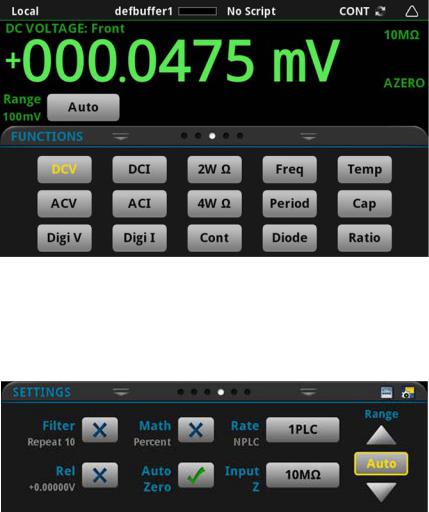
FUNCTIONS swipe screen
The FUNCTIONS swipe screen highlights the selected measure function and allows you to select a different function.
Figure 6: FUNCTIONS swipe screen
SETTINGS swipe screen
The SETTINGS swipe screen gives you front-panel access to some instrument settings for the selected measure function. It shows you the present settings and allows you to change them. The available settings depend on which measure function is active.
Figure 7: SETTINGS swipe screen
To disable or enable a setting, select the box next to the setting so that it shows an X (disabled) or a check mark (enabled).
DMM6500-900-01Rev. A / April 2018 |
2-9 |
Section 2: Front-panel overview |
DMM6500 6½ Digit Multimeter User's Manual |
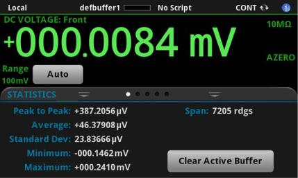
STATISTICS swipe screen
The STATISTICS swipe screen contains information about the readings in the active reading buffer. When the reading buffer is configured to fill continuously and overwrite old data with new data, the buffer statistics include the data that was overwritten. To get statistics that do not include data that has been overwritten, define a large buffer size that will accommodate the number of readings you will make. You can use the Clear Active Buffer button on this screen to clear the data from the active reading buffer.
If multiple watch channels are set up, you can use the Channel arrows to change the display to show the statistics for each watch channel.
Figure 8: STATISTICS swipe screen
2-10 |
DMM6500-900-01Rev. A / April 2018 |
DMM6500 6½ Digit Multimeter User's Manual |
Section 2: Front-panel overview |
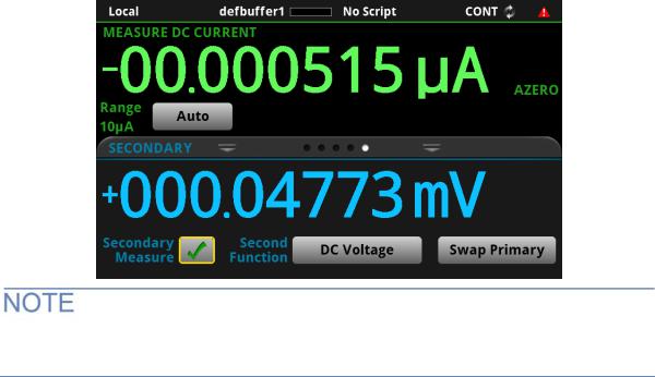
SECONDARY swipe screen
The SECONDARY swipe screen allows you to display the results of two measurements on the front-panel display.
To start displaying secondary measurements, select the Second Function and select Secondary Measure. Secondary measurements are only available in Continuous Measurement Mode and Manual Trigger Mode. This feature is only available from the front panel of the instrument.
Refer to "Display results of two measure functions" in the Model DMM6500 Reference Manual.
Figure 9: SECONDARY swipe screen
Depending on the selected functions, a relay may click when the instrument switches between the measurement types. Leaving secondary measurements on for extended periods may shorten the life of the relays.
DMM6500-900-01Rev. A / April 2018 |
2-11 |

Section 2: Front-panel overview |
DMM6500 6½ Digit Multimeter User's Manual |
USER swipe screen
If you program custom text, it is displayed on the USER swipe screen. For example, you can program the DMM6500 to show that a test is in process. This swipe screen is only displayed if custom text has been displayed. Refer to "Customizing a message for the USER swipe screen" in the Model DMM6500 Reference Manual.
Figure 10: User swipe screen
GRAPH swipe screen
The GRAPH swipe screen shows a graphical representation of the readings in the presently selected reading buffer.
Figure 11: GRAPH swipe screen
2-12 |
DMM6500-900-01Rev. A / April 2018 |
DMM6500 6½ Digit Multimeter User's Manual |
Section 2: Front-panel overview |
To view the graph in the full screen and to access graph settings, select the graph icon on the right side of the swipe screen header. You can also open the full-function Graph screen by pressing the MENU key and selecting Graph under Views.
For more information about graphing measurements, see "Graphing" in the Model DMM6500 Reference Manual.
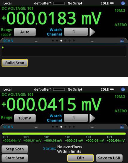
SCAN swipe screen
The SCAN swipe screen gives you front-panel access to build a scan, edit a scan, start a scan, step through a scan, and display scan results. You can also save the scan results to a USB flash drive.
The icon on the right side of the swipe screen heading bar is a shortcut to the Channel Scan menu. You can also use the Channel Scan menu to build or edit a scan.
For more information about viewing a scan preview and editing or running a scan, see "Channel scan menu" in the Model DMM6500 Reference Manual.
Figure 12: SCAN swipe screen - initial view
Figure 13: SCAN swipe screen - scan results
DMM6500-900-01Rev. A / April 2018 |
2-13 |

Section 2: Front-panel overview |
DMM6500 6½ Digit Multimeter User's Manual |
The SCAN swipe screen has the following control options:
Button |
Description |
|
|
Abort Scan |
Stop the scan. |
|
|
Build Scan |
Opens the SCAN screen, where you can set up a new scan. |
|
|
Edit |
Opens the SCAN screen, where you can change the setup of a scan. |
|
|
Pause Scan |
Pauses the scan until Resume Scan is selected. |
|
|
Resume Scan |
Resumes a paused scan. |
|
|
Save to USB |
Saves the data in the scan reading buffer to a CSV file on the USB flash drive. |
|
|
Start Scan |
Runs a scan. |
|
|
Step Scan |
Incrementally steps through a scan, channel by channel. |
|
|
Menu overview
To access the main menu, press the MENU key on the DMM6500 front panel. The figure below shows the organization of the main menu.
Figure 14: DMM6500 main menu
The main menu includes submenus that are labeled in green across the top of the display. Selecting an option in a submenu opens an interactive screen.
2-14 |
DMM6500-900-01Rev. A / April 2018 |

DMM6500 6½ Digit Multimeter User's Manual |
Section 2: Front-panel overview |
Channel menu
The Channel menus allow you to set up and control channels and scans from the front panel.
The Channel Settings menu allows you to select and configure channels.
The Channel Control menu contains options to open and close channels.
The Channel Scan menu contains options to set up and run scans. Options include control of groups, which are channels that are sequential and have the same functions applied to them.
Measure Menu
The Measure menus allow you to select, configure, and perform measure operations from the front panel.
The QuickSet menu allows you to change the function and adjust performance.
The Measure Settings menu contains settings for the presently selected measure function, which is identified by the function indicator in the upper right corner of the menu. The available settings depend on the front-panel FUNCTION key selection.
The Calculations menu contains settings that specify the way measurement information is processed and returned.
The Reading Buffers menu allows you to view the list of existing reading buffers and select one to be the active buffer. You can also create, save, delete, resize, and clear buffers from this screen.
DMM6500-900-01Rev. A / April 2018 |
2-15 |

Section 2: Front-panel overview |
DMM6500 6½ Digit Multimeter User's Manual |
Views menu
The Views menus allow you to select, configure, and view data that was gathered from measure operations.
The Graph menu opens a screen that displays a graph of the measurements in selected reading buffers as traces. It also contains tabs that you use to customize the graph display.
You can also select the trigger mode and initiate the trigger model or scan from this screen.
The Histogram menu allows you to graph the distribution of measurement data in the selected reading buffer. It also contains tabs that you use to customize the histogram.
The Reading Table menu allows you to view data in the selected reading buffer.
Trigger menu
The Trigger menus allow you to configure the trigger model from the front panel.
The Templates menu allows you to choose from one of several preprogrammed trigger models. When you select a template, settings you can specify for that template are shown in the lower part of the screen.
The Configure menu allows you to view and modify the structure and parameters of a trigger model. You can also monitor trigger model operation.
2-16 |
DMM6500-900-01Rev. A / April 2018 |
 Loading...