


Model 2400 Series SourceMeter®
Quick Results Guide
A G R E A T E R M E A S U R E O F C O N F I D E N C E

WARRANTY
Keithley Instruments, Inc. warrants this product to be free from defects in material and workmanship for a period of 1 year from date of shipment.
Keithley Instruments, Inc. warrants the following items for 90 days from the date of shipment: probes, cables, rechargeable batteries, diskettes, and documentation.
During the warranty period, we will, at our option, either repair or replace any product that proves to be defective.
To exercise this warranty, write or call your local Keithley representative, or contact Keithley headquarters in Cleveland, Ohio. You will be given prompt assistance and return instructions. Send the product, transportation prepaid, to the indicated service facility. Repairs will be made and the product returned, transportation prepaid. Repaired or replaced products are warranted for the balance of the original warranty period, or at least 90 days.
LIMITATION OF WARRANTY
This warranty does not apply to defects resulting from product modification without Keithley’s express written consent, or misuse of any product or part. This warranty also does not apply to fuses, software, non-rechargeable batteries, damage from battery leakage, or problems arising from normal wear or failure to follow instructions.
THIS WARRANTY IS IN LIEU OF ALL OTHER WARRANTIES, EXPRESSED OR IMPLIED, INCLUDING ANY IMPLIED WARRANTY OF MERCHANTABILITY OR FITNESS FOR A PARTICULAR USE. THE REMEDIES PROVIDED HEREIN ARE BUYER’S SOLE AND EXCLUSIVE REMEDIES.
NEITHER KEITHLEY INSTRUMENTS, INC. NOR ANY OF ITS EMPLOYEES SHALL BE LIABLE FOR ANY DIRECT, INDIRECT, SPECIAL, INCIDENTAL OR CONSEQUENTIAL DAMAGES ARISING OUT OF THE USE OF ITS INSTRUMENTS AND SOFTWARE EVEN IF KEITHLEY INSTRUMENTS, INC., HAS BEEN ADVISED IN ADVANCE OF THE POSSIBILITY OF SUCH DAMAGES. SUCH EXCLUDED DAMAGES SHALL INCLUDE, BUT ARE NOT LIMITED TO: COSTS OF REMOVAL AND INSTALLATION, LOSSES SUSTAINED AS THE RESULT OF INJURY TO ANY PERSON, OR DAMAGE TO PROPERTY.
|
|
|
|
Keithley Instruments, Inc. |
28775 Aurora Road • Cleveland, Ohio 44139 • 440-248-0400 • Fax: 440-248-6168 |
||
|
|
|
1-888-KEITHLEY (534-8453) • www.keithley.com |
Sales Offices: BELGIUM: |
Bergensesteenweg 709 • B-1600 Sint-Pieters-Leeuw • 02-363 00 40 • Fax: 02/363 00 64 |
||
|
CHINA: |
Yuan Chen Xin Building, Room 705 • 12Yumin Road, Dewai, Madian • Beijing 100029 • 8610-6202-2886 • Fax: 8610-6202-2892 |
|
|
FINLAND: |
Tietäjäntie 2 • 02130 Espoo • Phone: 09-54 75 08 10 • Fax: 09-25 10 51 00 |
|
|
FRANCE: |
3, allée des Garays • 91127 Palaiseau Cédex • 01-64 53 20 20 • Fax: 01-60 11 77 26 |
|
|
GERMANY: |
Landsberger Strasse 65 • 82110 Germering • 089/84 93 07-40 • Fax: 089/84 93 07-34 |
|
|
GREAT BRITAIN: |
Unit 2 Commerce Park, Brunel Road • Theale • Berkshire RG7 4AB • 0118 929 7500 • Fax: 0118 929 7519 |
|
|
INDIA: |
Flat 2B, Willocrissa • 14, Rest House Crescent • Bangalore 560 001 • 91-80-509-1320/21 • Fax: 91-80-509-1322 |
|
|
ITALY: |
Viale San Gimignano, 38 • 20146 Milano • 02-48 39 16 01 • Fax: 02-48 30 22 74 |
|
|
JAPAN: |
New Pier Takeshiba North Tower 13F • 11-1, Kaigan 1-chome • Minato-ku, Tokyo 105-0022 • 81-3-5733-7555 • Fax: 81-3-5733-7556 |
|
|
KOREA: |
2FL., URI Building • 2-14 Yangjae-Dong • Seocho-Gu, Seoul 137-888 • 82-2-574-7778 • Fax: 82-2-574-7838 |
|
|
NETHERLANDS: |
Postbus 559 • 4200 AN Gorinchem • 0183-635333 • Fax: 0183-630821 |
|
|
SWEDEN: |
c/o Regus Business Centre • Frosundaviks Allé 15, 4tr • 169 70 Solna • 08-509 04 679 • Fax: 08-655 26 10 |
|
|
SWITZERLAND: |
Kriesbachstrasse 4 • 8600 Dübendorf • 01-821 94 44 • Fax: 01-820 30 81 |
|
|
TAIWAN: |
1FL., 85 Po Ai Street • Hsinchu, Taiwan, R.O.C. • 886-3-572-9077 • Fax: 886-3-572-9031 |
|
4/02

2400 Series SourceMeter®
Quick Results Guide
©2000, Keithley Instruments, Inc.
All rights reserved.
Cleveland, Ohio, U.S.A.
Third Printing, May 2002
Document Number: 2400S-903-01 Rev. C

Manual Print History
The print history shown below lists the printing dates of all Revisions and Addenda created for this manual. The Revision Level letter increases alphabetically as the manual undergoes subsequent updates. Addenda, which are released between Revisions, contain important change information that the user should incorporate immediately into the manual. Addenda are numbered sequentially. When a new Revision is created, all Addenda associated with the previous Revision of the manual are incorporated into the new Revision of the manual. Each new Revision includes a revised copy of this print history page.
Revision A (Document Number 2400S-903-01) ........................................................ |
February 2000 |
Revision B (Document Number 2400S-903-01) .............................................................. |
April 2001 |
Revision C (Document Number 2400S-903-01) ............................................................... |
May 2002 |
All Keithley product names are trademarks or registered trademarks of Keithley Instruments, Inc. Other brand names are trademarks or registered trademarks of their respective holders.

Safety Precautions
The following safety precautions should be observed before using this product and any associated instrumentation. Although some instruments and accessories would normally be used with non-hazardous voltages, there are situations where hazardous conditions may be present.
This product is intended for use by qualified personnel who recognize shock hazards and are familiar with the safety precautions required to avoid possible injury. Read and follow all installation, operation, and maintenance information carefully before using the product. Refer to the manual for complete product specifications.
If the product is used in a manner not specified, the protection provided by the product may be impaired.
The types of product users are:
Responsible body is the individual or group responsible for the use and maintenance of equipment, for ensuring that the equipment is operated within its specifications and operating limits, and for ensuring that operators are adequately trained.
Operators use the product for its intended function. They must be trained in electrical safety procedures and proper use of the instrument. They must be protected from electric shock and contact with hazardous live circuits.
Maintenance personnel perform routine procedures on the product to keep it operating properly, for example, setting the line voltage or replacing consumable materials. Maintenance procedures are described in the manual. The procedures explicitly state if the operator may perform them. Otherwise, they should be performed only by service personnel.
Service personnel are trained to work on live circuits, and perform safe installations and repairs of products. Only properly trained service personnel may perform installation and service procedures.
Keithley products are designed for use with electrical signals that are rated Installation Category I and Installation Category II, as described in the International Electrotechnical Commission (IEC) Standard IEC 60664. Most measurement, control, and data I/O signals are Installation Category I and must not be directly connected to mains voltage or to voltage sources with high transient over-voltages. Installation Category II connections require protection for high transient over-voltages often associated with local AC mains connections. Assume all measurement, control, and data I/O connections are for connection to Category I sources unless otherwise marked or described in the Manual.
Exercise extreme caution when a shock hazard is present. Lethal voltage may be present on cable connector jacks or test fixtures. The American National Standards Institute (ANSI) states that a shock hazard exists when voltage levels greater than 30V RMS, 42.4V peak, or 60VDC are present. A good safety practice is to expect that hazardous voltage is present in any unknown circuit before measuring.
Operators of this product must be protected from electric shock at all times. The responsible body must ensure that operators are prevented access and/or insulated from every connection point. In some cases, connections must be exposed to potential human contact. Product operators in these circumstances must be trained to protect themselves from the risk of electric shock. If the circuit is capable of operating at or above 1000 volts, no conductive part of the circuit may be exposed.
Do not connect switching cards directly to unlimited power circuits. They are intended to be used with impedance limited sources. NEVER connect switching cards directly to AC mains. When connecting sources to switching cards, install protective devices to limit fault current and voltage to the card.
Before operating an instrument, make sure the line cord is connected to a properly grounded power receptacle. Inspect the connecting cables, test leads, and jumpers for possible wear, cracks, or breaks before each use.
When installing equipment where access to the main power cord is restricted, such as rack mounting, a separate main input power disconnect device must be provided, in close proximity to the equipment and within easy reach of the operator.
For maximum safety, do not touch the product, test cables, or any other instruments while power is applied to the circuit under test. ALWAYS remove power from the entire test system and discharge any capacitors before: connecting or disconnecting ca-
5/02

bles or jumpers, installing or removing switching cards, or making internal changes, such as installing or removing jumpers.
Do not touch any object that could provide a current path to the common side of the circuit under test or power line (earth) ground. Always make measurements with dry hands while standing on a dry, insulated surface capable of withstanding the voltage being measured.
The instrument and accessories must be used in accordance with its specifications and operating instructions or the safety of the equipment may be impaired.
Do not exceed the maximum signal levels of the instruments and accessories, as defined in the specifications and operating information, and as shown on the instrument or test fixture panels, or switching card.
When fuses are used in a product, replace with same type and rating for continued protection against fire hazard.
Chassis connections must only be used as shield connections for measuring circuits, NOT as safety earth ground connections.
If you are using a test fixture, keep the lid closed while power is applied to the device under test. Safe operation requires the use of a lid interlock.
If  or
or  is present, connect it to safety earth ground using the wire recommended in the user documentation.
The ! symbol on an instrument indicates that the user should refer to the operating instructions located in the manual.
The  symbol on an instrument shows that it can source or measure 1000 volts or more, including the combined effect of normal and common mode voltages. Use standard safety precautions to avoid personal contact with these voltages.
The WARNING heading in a manual explains dangers that might result in personal injury or death. Always read the associated information very carefully before performing the indicated procedure.
The CAUTION heading in a manual explains hazards that could damage the instrument. Such damage may invalidate the warranty.
Instrumentation and accessories shall not be connected to humans.
Before performing any maintenance, disconnect the line cord and all test cables.
To maintain protection from electric shock and fire, replacement components in mains circuits, including the power transformer, test leads, and input jacks, must be purchased from Keithley Instruments. Standard fuses, with applicable national safety approvals, may be used if the rating and type are the same. Other components that are not safety related may be purchased from other suppliers as long as they are equivalent to the original component. (Note that selected parts should be purchased only through Keithley Instruments to maintain accuracy and functionality of the product.) If you are unsure about the applicability of a replacement component, call a Keithley Instruments office for information.
To clean an instrument, use a damp cloth or mild, water based cleaner. Clean the exterior of the instrument only. Do not apply cleaner directly to the instrument or allow liquids to enter or spill on the instrument. Products that consist of a circuit board with no case or chassis (e.g., data acquisition board for installation into a computer) should never require cleaning if handled according to instructions. If the board becomes contaminated and operation is affected, the board should be returned to the factory for proper cleaning/servicing.

Table of Contents |
|
Introduction ................................................................................... |
1 |
Source-measure capabilities .......................................................... |
1 |
Front and rear panels ..................................................................... |
3 |
Navigating menus and entering numeric data ............................... |
4 |
Menu navigation .................................................................... |
4 |
Numeric data entry (EDIT keys) ............................................ |
4 |
Editing source and compliance values .......................................... |
4 |
Editing keys ........................................................................... |
4 |
Editing procedure ................................................................... |
5 |
Toggling the source and measure display fields ..................... |
5 |
Basic connections .......................................................................... |
5 |
Front/rear terminals selection ................................................ |
6 |
2-wire connections ................................................................. |
6 |
4-wire connections ................................................................. |
7 |
Cable guard ............................................................................ |
8 |
Ohms guard ............................................................................ |
8 |
Remote command programming .......................................... |
10 |
Basic SourceMeter operations .................................................... |
10 |
Source-measure .................................................................... |
10 |
Measure only (V or I) .......................................................... |
12 |
Measure ohms ...................................................................... |
13 |
Remote command programming .......................................... |
15 |
Settings to optimize performance ............................................... |
19 |
Range ................................................................................... |
19 |
Speed .................................................................................... |
19 |
Digits .................................................................................... |
20 |
Filter ..................................................................................... |
20 |
Rel (nulling offsets) ............................................................. |
21 |
Remote command programming .......................................... |
22 |
Features to enhance DUT testing ................................................ |
23 |
Data store ............................................................................. |
23 |
Sweep operation ................................................................... |
25 |
Performing sweeps ............................................................... |
29 |
Limit testing ......................................................................... |
34 |
Math functions ..................................................................... |
36 |
Pulse mode (Model 2430 only) ............................................ |
40 |

List of Illustrations |
|
|
Figure 1 |
Front panel ................................................................................ |
3 |
Figure 2 |
Rear panel .................................................................................. |
3 |
Figure 3 |
2-wire connections .................................................................... |
6 |
Figure 4 |
4-wire connections .................................................................... |
7 |
Figure 5 |
Cable guard connections ........................................................... |
8 |
Figure 6 |
Guarded ohms measurements ................................................... |
9 |
Figure 7 |
Linear staircase sweep ............................................................. |
25 |
Figure 8 |
Logarithmic staircase sweep (example) .................................. |
26 |
Figure 9 |
Custom pulse sweep (example) ............................................... |
27 |
Figure 10 |
Pulse-measure timing .............................................................. |
40 |
List of Tables |
|
|
Table 1 |
SCPI commands; terminals, sense, and cable guard ............... |
10 |
Table 2 |
Source-measure procedure ...................................................... |
11 |
Table 3 |
Measure only (V or I) procedure ............................................. |
12 |
Table 4 |
Auto ohms measurement procedure ........................................ |
13 |
Table 5 |
Manual ohms measurement procedure .................................... |
14 |
Table 6 |
SCPI commands; source-measure and measure only............... |
16 |
Table 7 |
SCPI commands; measure ohms ............................................. |
16 |
Table 8 |
Command sequence for source-measure example .................. |
17 |
Table 9 |
Command sequence for measure current only example .......... |
17 |
Table 10 |
Command sequence for auto ohms example ........................... |
18 |
Table 11 |
Command sequence for manual ohms example ...................... |
18 |
Table 12 |
SCPI commands; speed, digits, filter, and rel .......................... |
22 |
Table 13 |
SCPI commands; data store .................................................... |
24 |
Table 14 |
Command sequence for data store example ............................ |
24 |
Table 15 |
SCPI commands; sweeping ..................................................... |
31 |
Table 16 |
Command sequences for sweep examples .............................. |
32 |
Table 17 |
SCPI commands; basic non-binning limit testing ................... |
35 |
Table 18 |
Command sequence for Limit 2 test example ......................... |
36 |
Table 19 |
SCPI commands; built-in math functions ............................... |
39 |
Table 20 |
Command sequence for power measurement example ........... |
39 |
Table 21 |
SCPI commands; select and configure Pulse Mode ................ |
44 |
Table 22 |
Command sequence for Pulse Mode example ........................ |
44 |

2400 Series
SourceMeter
Quick Results Guide
Introduction
This guide is designed to familiarize users with fundamental operation (front panel and remote) of the Keithley 2400 Series SourceMeters. For comprehensive information on all aspects of SourceMeter operation, refer to the 2400 Series SourceMeter User’s Manual.
Operation information in this guide is divided into four parts; (1) Fundamental sourcemeasure operations, (2) Settings to optimize performance, (3) Features to enhance DUT testing and (4) More testing techniques. This format allows a new user to easily progress from basic simple operation to more complex procedures.
Remote command programming - For the various SourceMeter operating modes covered in this guide, the related SCPI commands for remote operation are summarized in tables. Most commands have a query form. For example, :OUTPut ON turns the output on, while :OUTPut? requests the present state of the output. Note that the SourceMeter must be addressed to talk after sending a query command.
For operations where command sequence is important, programming examples are provided. The exact programming syntax will depend on the test program language.
Source-measure capabilities
Model 2400:
•Source voltage from 5µV to 210V; measure voltage from 1µV to 211V.
•Source current from 50pA to 1.05A; measure current from 10pA to 1.055A.
• Measure resistance from 100µ Ω (<100µ Ω in manual ohms) to 211MΩ .
•Maximum source power is 22W.

2 Quick Results Guide
Model 2410:
•Source voltage from 5µV to 1100V; measure voltage from 1µV to 1100V.
•Source current from 50pA to 1.05A; measure current from 10pA to 1.055A.
• Measure resistance from 100µ Ω (<100µ Ω in manual ohms) to 211MΩ .
•Maximum source power is 22W.
Model 2420:
•Source voltage from 5µV to 63V; measure voltage from 1µV to 63.3V.
•Source current from 500pA to 3.15A; measure current from 100pA to 3.165A.
• Measure resistance from 10µ Ω (<10µ Ω in manual ohms) to 21.1MΩ .
•Maximum source power is 66W.
Model 2425:
•Source voltage from 5µV to 105V; measure voltage from 1µV to 105.5V.
•Source current from 500pA to 3.15A; measure current from 100pA to 3.165A.
• Measure resistance from 10µ Ω (<10µ Ω in manual ohms) to 21.1MΩ .
•Maximum source power is 110W.
Model 2430:
•Source DC or pulse voltage from 5µV to 105V; measure voltage from 1µV to 105.5V.
•Source DC current from 500pA to 3.15A; measure DC current from 100pA to 3.165A.
•Source pulse current from 500pA to 10.5A; measure pulse current from 100pA to 10.55A.
• Measure resistance from 10µ Ω (<10µ Ω in manual ohms) to 21.1MΩ .
•Maximum DC source power is 110W.
•Maximum pulse source power is 1.1kW.
Model 2440:
•Source voltage from 5µV to 42V; measure voltage from 1µV to 42V.
•Source current from 500pA to 5.25A; measure current from 100pA to 5.25A.
• Measure resistance from 10µ Ω (< 10 µ Ω in manual ohms) to 21.1 MΩ .
•Maximum source power is 55W.

Quick Results Guide |
3 |
|
|
Front and rear panels
The front and rear panels of the Model 2400 SourceMeter are shown in Figures 1 and 2. The front and rear panels of the other SourceMeter models are similar. The use of the various instrument controls and connectors will be explained throughout this guide.
Figure 1
Front panel
2400 SourceMeter
|
|
MEAS |
|
|
|
SOURCE |
|
|
EDIT |
V |
I |
Ω |
FCTN |
V |
I |
|
|
DISPLAY |
|
|
|
|
|
|
|
RANGE |
0 |
1 |
2 |
3 |
4 |
5 |
|
EDIT |
|
|
|
|||||||
TOGGLE |
LOCAL |
REL |
FILTER |
LIMIT |
TRIG |
SWEEP |
|
AUTO |
|
|
|
||||||
POWER |
6 |
7 |
8 |
9 |
+/- |
|
|
RANGE |
|
DIGITS |
SPEED |
STORE RECALL |
CONFIG |
MENU |
EXIT |
ENTER |
|
4-WIRE |
|
INPUT/ |
SENSE |
HI |
OUTPUT |
|
|
|
250V |
5V |
250V |
PEAK |
PEAK |
PEAK |
|
LO |
250V |
|
|
|
|
|
PEAK |
|
|
TERMINALS |
ON/OFF |
|
FRONT/ |
|
|
REAR |
OUTPUT |
|
|
Figure 2
Rear panel
WARNING: NO INTERNAL OPERATOR SERVICABLE PARTS, SERVICE BY QUALIFIED PERSONNEL ONLY.
|
HI |
5V |
|
|
|
|
|
PK |
|
MADE IN |
C UL US |
||
|
|
V, Ω , |
||||
|
|
|
|
U.S.A. |
||
|
|
|
|
GUARD |
|
|
|
|
|
|
|
|
LISTED |
250V |
5V |
250V |
|
5V |
LINE FUSE |
SourceMeter |
PEAK |
PEAK |
PEAK |
|
PEAK |
SLOWBLOW |
4ZA4 |
|
|
|
|
|
2.5A, 250V |
|
|
|
|
|
|
LINE RATING |
|
|
|
|
|
GUARD |
100-240VAC |
|
|
|
|
|
SENSE |
50, 60, Hz |
|
|
LO |
|
|
|
190VA MAX. |
|
4-WIRE |
INPUT/ |
|
|
|
|
|
|
250V |
CAT I |
FUSE DRAWER |
|
||
SENSE |
! |
OUTPUT |
PEAK |
|
||
|
|
|
||||
|
IEEE-488 |
|
|
|
|
|
(ENTER IEEE ADDRESS |
|
|
TRIGGER |
OUTPUT |
||
WITH FRONT PANEL MENU) |
|
|
||||
|
|
ENABLE |
||||
|
|
|
|
RS-232 |
LINK |
|
|
|
|
|
|
||
CAUTION: FOR CONTINUED PROTECTION AGAINST FIRE HAZARD, REPLACE FUSE WITH SAME TYPE AND RATING.

4 Quick Results Guide
Navigating menus and entering numeric data
Menu navigation
Many operating modes for the SourceMeter are configured using front panel menus. Throughout this guide, menu navigation will be presented as a sequence of key presses and menu item selections. For example, the following sequence selects the auto ohms source mode:
Press CONFIG > press MEAS Ω > select SOURCE > select AUTO
The above sequence is explained as follows:
1.Press the CONFIG key.
2.Press the MEAS Ω key.
3.Select the SOURCE menu item.
4.Select the AUTO ohms source mode.
A menu item is selected by placing the cursor on it and pressing the ENTER key. The andkeys control cursor position.
Numeric data entry (EDIT keys)
Numeric values must to be entered for some menu items. Numeric entry is also used to set source and compliance values. The edit keys for numeric entry include the EDIT and keys to control cursor position, EDIT and keys to increment or decrement the digit value, and the number keys.
After a value is keyed in, press ENTER to select it. Note that pressing MENU resets a displayed number to its minimum value.
Editing source and compliance values
Editing keys
Use the following keys to edit source and compliance values:
•DISPLAY EDIT — Selects the source or compliance display field for editing. A blinking cursor will appear in the field to be edited. If no key is pressed within a few seconds, the edit mode will be cancelled automatically.
•EDIT and — Places the display cursor on the display digit to be changed.
•SOURCE or — Increments or decrements the source or compliance value. Note that pressing either of these keys will automatically enable the source edit mode.
•RANGE or — Selects the source or compliance range.
•Numeric keys (0-9) — Allow you to directly enter source or compliance values.
•EXIT — Exits the edit mode without waiting for the time-out period.
Quick Results Guide |
5 |
|
|
Editing procedure
1.Press the DISPLAY EDIT key to place the blinking cursor in either the source or compliance display field to be edited.
2.If desired, use the RANGE and keys to select the desired source or compliance range.
3.To simply increment or decrement the display value, use the EDIT and keys to place the blinking cursor on the digit to be changed, then increment or decrement the value with the SOURCE and keys. Note that the source or compliance value will be updated immediately; you need not press ENTER to complete the process.
4.To enter the source or compliance value directly, simply key in the desired value with the numeric keys while the cursor is blinking. Again, the source or compliance value will be updated immediately.
Toggling the source and measure display fields
Normally, the measured reading value will appear in the upper, main display line, while the source and compliance values will appear in the left and right fields respectively of the lower display line. You can toggle the source and measure display fields by pressing the DISPLAY TOGGLE key to place the source and measure values in the desired display fields.
Basic connections
WARNING The SourceMeter uses safety jacks for signal connections. To avoid electric shock:
•Do not leave exposed connections.
•Properly insulate all external circuits.
•The front and rear terminals of the SourceMeters are rated for connection to circuits rated Installation Category I only. Do not connect the SourceMeter terminals to CAT II, CAT III, or CAT IV circuits. Connection of the SourceMeter Input/Output terminals, to circuits higher than CAT I, can cause damage to the equipment or expose the operator to hazardous voltages.
•Hazardous voltages may be present on the output and guard terminals. To prevent electrical shock that could cause injury or death, NEVER make or break connections to the SourceMeter while the unit is on. Power off the equipment from the front panel or disconnect the main power cord from the rear of the SourceMeter before handling cables connected to the outputs. Putting the equipment into standby mode does not guarantee the outputs are not powered if a hardware or software fault occurs.
The three basic connection configurations for the SourceMeter include 2-wire local sensing, 4-wire remote sensing, and cable guard.
NOTE Connections and details for in-circuit ohms measurements (ohms guard) are covered in the “Advanced operation” section of this guide.
6 Quick Results Guide
Front/rear terminals selection
The input/output and sense terminals are accessible from both the front and rear panels, while the guard terminals and chassis ground are only accessible from the rear panel. On the front panel, press the FRONT/REAR key to toggle between front and rear. The REAR annunciator indicates that the rear terminals are selected. With REAR off, the front terminals are selected.
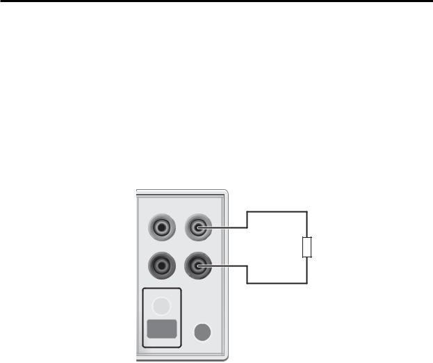
2-wire connections
Connections for 2-wire local sensing are shown in Figure 3. The following menu sequence selects 2-wire local sensing:
Press CONFIG > select SOURCE V (or ΜΕΑ S Ω ) > select SENSE MODE > select 2-WIRE
Figure 3
2-wire connections
4-WIRE |
INPUT/ |
SENSE |
OUTPUT |
|
HI |
|
DUT |
|
LO |
|
TERMINALS |
ON/OFF |
FRONT// |
|
REAR |
OUTPUT |
|
SourceMeter Front Panel |
Sense Selection: 2-wire |
Quick Results Guide |
7 |
|
|
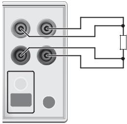
4-wire connections
Connections for 4-wire local sensing are shown in Figure 4. Use 4-wire remote sensing for the following source-measure conditions:
•Test circuit impedance is <1kΩ .
•Optimum ohms, V-source, and/or V-measure accuracy is required.
With 4-wire sensing selected, the 4W annunciator is on. The following menu sequence selects 4-wire remote sensing:
Press CONFIG > select SOURCE V (or MEAS Ω ) > select SENSE MODE > select 4-WIRE
NOTE
Figure 4
4-wire connections
Specified accuracies for both source and measure are achieved only using 4-wire remote sensing.
4-WIRE |
INPUT/ |
SENSE |
OUTPUT |
|
HI |
|
DUT |
|
LO |
|
TERMINALS |
ON/OFF |
FRONT/ |
|
REAR |
OUTPUT |
|
SourceMeter Front Panel |
Sense Selection: 4-wire |

8 Quick Results Guide
Cable guard
When testing high-impedance DUT (>1GΩ ), cable guard is used to drive the shields of cables and test fixtures to minimize leakage currents and input capacitance. A typical connection scheme using cable guard is shown in Figure 5. The following menu sequence selects cable guard:
Press CONFIG > press SOURCE V (or SOURCE I or MEAS Ω ) > select GUARD > select CABLE
The guard terminal of the SourceMeter is at virtually the same potential as input/output HI. Therefore, if there is hazardous voltage at input/output HI, it is also present on the guard shield for the test circuit.
WARNING To prevent injury from electric shock, the guard shield must be enclosed in a safety shield (i.e., test fixture) that is connected to safety earth ground (as shown in Figure 5).
Figure 5 |
Guard Shield |
Test Fixture |
|
|
Cable guard connections
DUT
Connect to earth safety ground using #18 AWG wire or larger.
WARNING:NO INTERNAL OPERATOR SERVICAB
HI
V, Ω
GUARD
GUARD SENSE
LO
4-WIRE INPUT/
SENSE OUTPUT
IEEE-488
(ENTER IEEE ADDRESS WITH FRONT PANEL MENU)
RS232
CAUTION:FOR CONTINUED PROTECTION AGAINST FIR
Ohms guard
Ohms guard allows in-circuit resistance measurements on DUT where other parasitic leakage devices are present. Connection schemes for a Delta DUT configuration is shown in Figure 6.
 Loading...