


 Loading...
www.keithley.com
Model 2231A-30-3
Triple-channel DC Power Supply
Reference Manual
077-1004-01 / September 2014
*P077100401*
077-1004-01
A Tektr onix Company
Model 2231A-30-3
Triple-Channel DC Power Supply
Reference Manual
©2014, Keithley Instruments. Cleveland, Ohio, U.S.A.
All rights reserved.
Any unauthorized reproduction, photocopy, or use of the information herein, in whole or in part, without the prior written approval of Keithley Instruments. is strictly prohibited.
All Keithley Instruments product names are trademarks or registered trademarks of Keithley Instruments. Other brand names are trademarks or registered trademarks of their respective holders.
Document number: 077100401 / September 2014

Safety precautions
The following safety precautions should be observed before using this product and any associated instrumentation. Although some instruments and accessories would normally be used with nonhazardous voltages, there are situations where hazardous conditions may be present.
This product is intended for use by qualified personnel who recognize shock hazards and are familiar with the safety precautions required to avoid possible injury. Read and follow all installation, operation, and maintenance information carefully before using the product. Refer to the user documentation for complete product specifications.
If the product is used in a manner not specified, the protection provided by the product warranty may be impaired.
The types of product users are:
Responsible body is the individual or group responsible for the use and maintenance of equipment, for ensuring that the equipment is operated within its specifications and operating limits, and for ensuring that operators are adequately trained.
Operators use the product for its intended function. They must be trained in electrical safety procedures and proper use of the instrument. They must be protected from electric shock and contact with hazardous live circuits.
Maintenance personnel perform routine procedures on the product to keep it operating properly, for example, setting the line voltage or replacing consumable materials. Maintenance procedures are described in the user documentation. The procedures explicitly state if the operator may perform them. Otherwise, they should be performed only by service personnel.
Service personnel are trained to work on live circuits, perform safe installations, and repair products. Only properly trained service personnel may perform installation and service procedures.
Keithley Instruments products are designed for use with electrical signals that are measurement, control, and data I/O connections, with low transient overvoltages, and must not be directly connected to mains voltage or to voltage sources with high transient overvoltages. Measurement Category II (as referenced in IEC 60664) connections require protection for high transient overvoltages often associated with local AC mains connections. Certain Keithley measuring instruments may be connected to mains. These instruments will be marked as category II or higher.
Unless explicitly allowed in the specifications, operating manual, and instrument labels, do not connect any instrument to mains.
Exercise extreme caution when a shock hazard is present. Lethal voltage may be present on cable connector jacks or test fixtures. The American National Standards Institute (ANSI) states that a shock hazard exists when voltage levels greater than 30 V RMS, 42.4 V peak, or 60 VDC are present. A good safety practice is to expect that hazardous voltage is present in any unknown circuit before measuring.
Operators of this product must be protected from electric shock at all times. The responsible body must ensure that operators are prevented access and/or insulated from every connection point. In some cases, connections must be exposed to potential human contact. Product operators in these circumstances must be trained to protect themselves from the risk of electric shock. If the circuit is capable of operating at or above 1000 V, no conductive part of the circuit may be exposed.
Do not connect switching cards directly to unlimited power circuits. They are intended to be used with impedance-limited sources. NEVER connect switching cards directly to AC mains. When connecting sources to switching cards, install protective devices to limit fault current and voltage to the card.
Before operating an instrument, ensure that the line cord is connected to a properly-grounded power receptacle. Inspect the connecting cables, test leads, and jumpers for possible wear, cracks, or breaks before each use.
When installing equipment where access to the main power cord is restricted, such as rack mounting, a separate main input power disconnect device must be provided in close proximity to the equipment and within easy reach of the operator.
For maximum safety, do not touch the product, test cables, or any other instruments while power is applied to the circuit under test. ALWAYS remove power from the entire test system and discharge any capacitors before: connecting or disconnecting cables or jumpers, installing or removing switching cards, or making internal changes, such as installing or removing jumpers.
Do not touch any object that could provide a current path to the common side of the circuit under test or power line (earth) ground. Always make measurements with dry hands while standing on a dry, insulated surface capable of withstanding the voltage being measured.
For safety, instruments and accessories must be used in accordance with the operating instructions. If the instruments or accessories are used in a manner not specified in the operating instructions, the protection provided by the equipment may be

impaired.
Do not exceed the maximum signal levels of the instruments and accessories, as defined in the specifications and operating information, and as shown on the instrument or test fixture panels, or switching card.
When fuses are used in a product, replace with the same type and rating for continued protection against fire hazard.
Chassis connections must only be used as shield connections for measuring circuits, NOT as protective earth (safety ground) connections.
If you are using a test fixture, keep the lid closed while power is applied to the device under test. Safe operation requires the use of a lid interlock.
If a  screw is present, connect it to protective earth (safety ground) using the wire recommended in the user documentation.
The  symbol on an instrument means caution, risk of danger. The user must refer to the operating instructions located in the user documentation in all cases where the symbol is marked on the instrument.
The  symbol on an instrument means caution, risk of electric shock. Use standard safety precautions to avoid personal contact with these voltages.
The |
symbol on an instrument shows that the surface may be hot. Avoid personal contact to prevent burns. |
The  symbol indicates a connection terminal to the equipment frame.
If this  symbol is on a product, it indicates that mercury is present in the display lamp. Please note that the lamp must be properly disposed of according to federal, state, and local laws.
The WARNING heading in the user documentation explains dangers that might result in personal injury or death. Always read the associated information very carefully before performing the indicated procedure.
The CAUTION heading in the user documentation explains hazards that could damage the instrument. Such damage may invalidate the warranty.
Instrumentation and accessories shall not be connected to humans.
Before performing any maintenance, disconnect the line cord and all test cables.
To maintain protection from electric shock and fire, replacement components in mains circuits — including the power transformer, test leads, and input jacks — must be purchased from Keithley Instruments. Standard fuses with applicable national safety approvals may be used if the rating and type are the same. Other components that are not safety-related may be purchased from other suppliers as long as they are equivalent to the original component (note that selected parts should be purchased only through Keithley Instruments to maintain accuracy and functionality of the product). If you are unsure about the applicability of a replacement component, call a Keithley Instruments office for information.
To clean an instrument, use a damp cloth or mild, water-based cleaner. Clean the exterior of the instrument only. Do not apply cleaner directly to the instrument or allow liquids to enter or spill on the instrument. Products that consist of a circuit board with no case or chassis (e.g., a data acquisition board for installation into a computer) should never require cleaning if handled according to instructions. If the board becomes contaminated and operation is affected, the board should be returned to the factory for proper cleaning/servicing.
Safety precaution revision as of January 2013.
|
Table of Contents |
Introduction.............................................................................................................. |
1-1 |
Welcome .............................................................................................................................. |
1-1 |
Extended warranty ............................................................................................................... |
1-1 |
Contact information .............................................................................................................. |
1-1 |
CD-ROM contents................................................................................................................ |
1-2 |
Key features ......................................................................................................................... |
1-2 |
Standard accessories........................................................................................................... |
1-2 |
Optional accessories............................................................................................................ |
1-3 |
Available services ................................................................................................................ |
1-3 |
General ratings..................................................................................................................... |
1-3 |
Quick reference........................................................................................................ |
2-1 |
Front-panel overview............................................................................................................ |
2-1 |
Rear panel overview ............................................................................................................ |
2-2 |
Installing the system............................................................................................................. |
2-2 |
Dimensions ............................................................................................................................... |
2-2 |
Adjust the carrying handle......................................................................................................... |
2-3 |
Power the instrument on or off .................................................................................................. |
2-4 |
Self-test procedure............................................................................................................... |
2-6 |
Check the output .................................................................................................................. |
2-7 |
Voltage output check................................................................................................................. |
2-7 |
Current output check................................................................................................................. |
2-8 |
What to do if the power supply does not turn on ................................................................. |
2-8 |
General operation .................................................................................................... |
3-1 |
Front-panel operation overview ........................................................................................... |
3-1 |
Panel description.................................................................................................................. |
3-2 |
Indicator description ............................................................................................................. |
3-3 |
Basic settings ....................................................................................................................... |
3-3 |
Set the voltage output or voltage limit for a specific channel..................................................... |
3-3 |
Set the current output or current limit for a specific channel ..................................................... |
3-3 |
Save and recall the setups........................................................................................................ |
3-3 |
Menu description.................................................................................................................. |
3-4 |
Default Set ................................................................................................................................ |
3-4 |
Enable Channels....................................................................................................................... |
3-5 |
Protection Settings .................................................................................................................... |
3-5 |
Track CH1/CH2......................................................................................................................... |
3-6 |
Combine CH1+CH2 .................................................................................................................. |
3-7 |
User Settings............................................................................................................................. |
3-9 |
System Info ............................................................................................................................. |
3-10 |
Overtemperature protection (OTP) .................................................................................... |
3-11 |

Table of Contents Model 2231A-30-3 Triple-Channel DC Power Supply Reference Manual
Remote communication........................................................................................... |
4-1 |
Communication interface ..................................................................................................... |
4-1 |
2231A-001 communication connector ................................................................................. |
4-1 |
SCPI command reference........................................................................................ |
5-1 |
Common commands ............................................................................................................ |
5-2 |
*CLS.......................................................................................................................................... |
5-2 |
*ESE ......................................................................................................................................... |
5-2 |
*ESR? ....................................................................................................................................... |
5-3 |
*IDN? ........................................................................................................................................ |
5-3 |
*OPC......................................................................................................................................... |
5-3 |
*RST ......................................................................................................................................... |
5-3 |
*SRE ......................................................................................................................................... |
5-4 |
*STB?........................................................................................................................................ |
5-4 |
*TRG ......................................................................................................................................... |
5-4 |
*SAV ......................................................................................................................................... |
5-5 |
*RCL ......................................................................................................................................... |
5-5 |
*TST?........................................................................................................................................ |
5-5 |
*WAI.......................................................................................................................................... |
5-5 |
*PSC ......................................................................................................................................... |
5-6 |
APPly subsystem ................................................................................................................. |
5-6 |
[SOURce:]APPLy...................................................................................................................... |
5-6 |
[SOURce:]APPly:VOLTage[:LEVel][:IMMediate][:AMPLitude] .................................................. |
5-6 |
[SOURce:]APPly:CURRent[:LEVel][:IMMediate][:AMPLitude] .................................................. |
5-7 |
CALibration subsystem ........................................................................................................ |
5-7 |
CALibration:SECure:[STATe].................................................................................................... |
5-7 |
CALibrate:VOLTage:LEVel ....................................................................................................... |
5-7 |
CALibrate:VOLTage[:DATA] <numeric value>}......................................................................... |
5-8 |
CALibrate:CURRent:LEVel ....................................................................................................... |
5-8 |
CALibrate:CURRent[:DATA] {<numeric value>} ..................................................................... |
5-8 |
CALibration:SAVe ..................................................................................................................... |
5-9 |
CALibration:INITital ................................................................................................................... |
5-9 |
CALibrate:STRing ..................................................................................................................... |
5-9 |
DISPlay subsystem .............................................................................................................. |
5-9 |
DISPlay[:WINDow][:STATe]...................................................................................................... |
5-9 |
DISPlay[:WINDow]:TEXT[:DATA] ........................................................................................... |
5-10 |
DISPlay[:WINDow]:TEXT:CLEar............................................................................................. |
5-10 |
INSTrument subsystem...................................................................................................... |
5-10 |
INSTrument[:SELect] .............................................................................................................. |
5-10 |
INSTrument:NSELect.............................................................................................................. |
5-11 |
INSTrument:COMbine:SERies................................................................................................ |
5-11 |
INSTrument:COMbine:PARAllel.............................................................................................. |
5-11 |
INSTrument:COMbine:TRACk ................................................................................................ |
5-12 |
INSTrument:COMbine:OFF..................................................................................................... |
5-12 |
INSTrument:COUPle[:TRIGger] .............................................................................................. |
5-12 |
MEASure subsystem.......................................................................................................... |
5-12 |
MEASure[:SCALar]:VOLTage[:DC]?....................................................................................... |
5-13 |
FETCh[:VOLTage][:DC]? ........................................................................................................ |
5-13 |
MEASure[:SCALar]:CURRent[:DC]?....................................................................................... |
5-13 |
FETCh:CURRent[:DC]? .......................................................................................................... |
5-13 |
MEASure[:SCALar]:POWer[:DC]? .......................................................................................... |
5-13 |
FETCh:POWer[:DC]?.............................................................................................................. |
5-13 |

Model 2231A-30-3 Triple-Channel DC Power Supply Reference Manual Table of Contents
OUTPut subsystem ............................................................................................................ |
5-14 |
OUTPut[:STATe][:ALL]............................................................................................................ |
5-14 |
CHANnel:OUTPut[:STATe] ..................................................................................................... |
5-14 |
OUTPut:ENABle...................................................................................................................... |
5-14 |
OUTPut:TIMer[:STATe]........................................................................................................... |
5-15 |
OUTPut:TIMer:DELay ............................................................................................................. |
5-15 |
OUTPut:TRACk[:STATe]......................................................................................................... |
5-15 |
OUTPut:SERies[:STATe] ........................................................................................................ |
5-16 |
OUTPut: PARallel [:STATe] .................................................................................................... |
5-16 |
SYSTem subsystem........................................................................................................... |
5-17 |
SYSTem:ERRor? .................................................................................................................... |
5-17 |
SYSTem:VERSion? ................................................................................................................ |
5-17 |
SYSTem:REMote.................................................................................................................... |
5-17 |
SYSTem:LOCal....................................................................................................................... |
5-17 |
SYSTem:RWLock ................................................................................................................... |
5-18 |
SYSTem:MODUle? ................................................................................................................. |
5-18 |
SYSTem:BEEPer .................................................................................................................... |
5-18 |
STATus subsystem ............................................................................................................ |
5-19 |
STATus:QUEStionable[:EVENt]?............................................................................................ |
5-19 |
STATus:QUEStionable:ENABle.............................................................................................. |
5-19 |
STATus:QUEStionable:CONDition? ....................................................................................... |
5-19 |
STATus:PRESet ..................................................................................................................... |
5-20 |
STATus:QUEStionable:INSTrument[:EVENt]?........................................................................ |
5-20 |
STATus:QUEStionable:INSTrument:ENABle.......................................................................... |
5-20 |
STATus:QUEStionable:INSTrument:ISUMmary<x>[:EVENt]?................................................ |
5-20 |
STATus:QUEStionable:INSTrument:ISUMmary<X>:ENABle ................................................. |
5-21 |
STATus:QUEStionable:INSTrument:ISUMmary<x>:CONDition? ........................................... |
5-21 |
STATus:OPERation[:EVENt]?................................................................................................. |
5-21 |
STATus:OPERation:CONDition? ............................................................................................ |
5-22 |
STATus:OPERation:ENABle................................................................................................... |
5-22 |
STATus:OPERation:INSTrument[:EVENt]? ............................................................................ |
5-22 |
STATus:OPERation:INSTrument:ENABle .............................................................................. |
5-23 |
STATus:OPERation:INSTrument:ISUMmary<x>[:EVENt]? .................................................... |
5-23 |
STATus:OPERation:INSTrument:ISUMmary<x>:ENABle....................................................... |
5-23 |
STATus:OPERation:INSTrument:ISUMmary<x>:CONDition? ................................................ |
5-23 |
SOURce subsystem........................................................................................................... |
5-24 |
[SOURce:]CHANnel:OUTPut[:STATe] .................................................................................... |
5-24 |
[SOURce:]CURRent[:LEVel][:IMMediate][:AMPLitude]........................................................... |
5-24 |
[SOURce:]CURRent[:LEVel]:UP[:IMMediate][:AMPLitude] ..................................................... |
5-24 |
[SOURce:]CURRent[:LEVel]:DOWN[:IMMediate][:AMPLitude]............................................... |
5-25 |
[SOURce:]CURRent[:LEVel][:IMMediate]:STEP[:INCRement]................................................ |
5-25 |
[SOURce:]CURRent[:LEVel]:TRIGgered[:IMMediate][:INCRement] ....................................... |
5-25 |
[SOURce:]VOLTage[:LEVel][:IMMediate][:AMPLitude]........................................................... |
5-26 |
[SOURce:]VOLTage[:LEVel]:UP[:IMMediate][:AMPLitude] ..................................................... |
5-26 |
[SOURce:]VOLTage[:LEVel]:DOWN[:IMMediate][:AMPLitude]............................................... |
5-26 |
[SOURce:]VOLTage[:LEVel][:IMMediate]:STEP[:INCRement]................................................ |
5-27 |
[SOURce:]VOLTage[:LEVel]:TRIGgered[:IMMediate][:INCRement] ....................................... |
5-27 |
[SOURce:]VOLTage:LIMIT[:LEVel] ......................................................................................... |
5-27 |
[SOURce:]VOLTage:LIMit:STATe........................................................................................... |
5-28 |
Status model ...................................................................................................................... |
5-29 |
Error messages.................................................................................................................. |
5-31 |
Additional Information............................................................................................. |
6-1 |
Additional Model 2231A-30-3 information............................................................................ |
6-1 |

Table of Contents Model 2231A-30-3 Triple-Channel DC Power Supply Reference Manual
Maintenance ............................................................................................................. |
A-1 |
Introduction .......................................................................................................................... |
A-1 |
Line fuse replacement.......................................................................................................... |
A-1 |
Cleaning the front-panel display .......................................................................................... |
A-2 |

Section 1
Introduction
In this section:
Welcome .................................................................................. |
1-1 |
Extended warranty.................................................................... |
1-1 |
Contact information .................................................................. |
1-1 |
CD-ROM contents .................................................................... |
1-2 |
Button features ......................................................................... |
1-2 |
Standard accessories............................................................... |
1-2 |
Optional accessories ................................................................ |
1-3 |
Available services..................................................................... |
1-3 |
General ratings......................................................................... |
1-3 |
Welcome
Thank you for using a Keithley Instruments product. The Model 2231A-30-3 Trip-Channel Programmable DC Power Supply is a flexible DC source designed to power a wide range of applications. It offers three independent and isolated power channels, allowing you to power circuits with different references or polarities. Each channel can be enabled or disabled as your application requires. Basic current accuracy is 0.2% for all channels and linear regulation delivers low noise – less than 5 mVpp. Flexible display modes make it easy to use the two 30 V outputs in combination, and the DB9 interface connector makes it easy to build PC-based systems. This compact power supply covers a wide range of applications without covering a lot of bench space.
Extended warranty
Additional years of warranty coverage are available on many products. These valuable contracts protect you from unbudgeted service expenses and provide additional years of protection at a fraction of the price of a repair. Extended warranties are available on new and existing products. Contact your local Keithley Instruments office, sales partner, or distributor for details.
Contact information
If you have any questions after you review the information in this documentation, please contact your local Keithley Instruments office, sales partner, or distributor, or call Keithley Instruments corporate headquarters (toll-free inside the U.S. and Canada only) at 1-888-KEITHLEY (1-888-534-8453), or from outside the U.S. at +1-440-248-0400. For worldwide contact numbers, visit the Keithley Instruments website (http://www.keithley.com).
Section 1 Introduction |
Model 2231A Triple-channel DC Power Supply Reference Manual |
CD-ROM contents
The Model 2231A-30-3 Product Information CD-ROM is shipped with each power supply. The Product Information CD-ROM contains:
•Reference Manual: Includes basic operation topics and maintenance information.
•Performance Verification: Contains performance verification procedures. Additional test equipment is required to complete the verification procedures.
•Accessories information: Documentation for accessories that are available for the Model 2231A-30-3.
For the latest drivers and additional support information, see the Keithley Instruments website (http://www.keithley.com).
Key features
The Model 2231A-30-3 has the following features:
Three isolated output channels, including two 30 V at 3 A channels and one 5 V at 3 A channel
0.06% basic voltage accuracy
0.2% basic current accuracy
Less than 5 mVpp ripple and noise
Intelligent fan control, energy conservation and noise reduction
Overvoltage and overtemperature protection
Standard accessories
Accessory |
Part number |
|
|
Documentation CD |
077102700 |
Calibration report |
001165500 |
You will also get one of the following power cords:
Option |
Description |
|
|
Option A0 |
North America and South America. The factory sets the line-voltage selector switch to 110 V. |
Option A1 |
Universal Euro. The factory sets the line-voltage selector switch to 220 V. |
Option A2 |
United Kingdom. The factory sets the line-voltage selector switch to 220 V. |
Option A3 |
Australia. The factory sets the line-voltage selector switch to 220 V |
Option A4 |
Chile, Italy. The factory sets the line-voltage selector switch to 220 V. |
Option A5 |
Switzerland. The factory sets the line-voltage selector switch to 220 V. |
Option A7 |
Israel. The factory sets the line-voltage selector switch to 220 V. |
Option A8 |
Argentina. The factory sets the line-voltage selector switch to 220 V. |
Option A9 |
China. The factory sets the line-voltage selector switch to 220 V. |
Option A10 |
India. The factory sets the line-voltage selector switch to 220 V. |
Option A11 |
India. The factory sets the line-voltage selector switch to 220 V. |
Option A13 |
Macao, Pakistan, Africa. The factory sets the line-voltage selector switch to 220 V. |
1-2 |
077100401/September 2014 |

Model 2231A-30-3 Triple-channel DC power supply Reference Manual Section1:Introduction
Optional accessories
Optional accessory |
Model number |
|
|
USB communication adapter |
2231A-001 |
Available services
For the current list of available services and accessories, upgrades, and options for your instrument, visit the Keithley Instruments website (http://www.keithley.com).
Service |
Model Number |
|
|
3-year factory warranty extended to 5 years from date of shipment |
2231A-30-3-5Y-EW |
3-year factory warranty extended to 1 additional year from date of |
2230A-30-3-EW |
shipment |
|
General ratings
The Model 2231A-30-3 instrument's general ratings and connections are listed in the following table.
When the mains power supplied to the Model 2231A-30-3 exceeds 253 V, the maximum operating time at maximum output power is 1 hour. At the supply voltage range of 110 V, when the mains power exceeds 132 V, the maximum operating time at maximum output power is 1 hour.
Category |
Specification |
|
|
|
|
Supply voltage range |
• 110: 110 |
V-120 V |
|
• 220: 220 |
V-230 V |
|
Each range capable of +/-10% tolerance, 47 to 63 Hz. |
|
|
Selectable by the line-voltage selector switch in the rear panel. |
|
Environmental conditions |
For indoor use only |
|
|
Operating: 0 |
°C to 40 °C (32 °F to 104 °F), 5% to 80% relative humidity |
|
at up to 40 °C (104 °F) |
|
|
Storage: −20 °C to 70 °C (-4 °F to 158 °F) |
|
|
5% to 80% relative humidity at up to +40°C (104 °F) and 5% to 60% |
|
|
relative humidity above +40°C (104°F) up to +70°C (158°F) |
|
|
Pollution degree: 2 |
|
077100401/September 2014 |
1-3 |
Section 2
Quick reference
In this section:
Front-panel overview ................................................................ |
2-1 |
Rear panel overview................................................................. |
2-2 |
Installing the system ................................................................. |
2-2 |
Self-test procedure ................................................................... |
2-6 |
Check the output ...................................................................... |
2-7 |
What to do if the power supply does not turn on....................... |
2-8 |
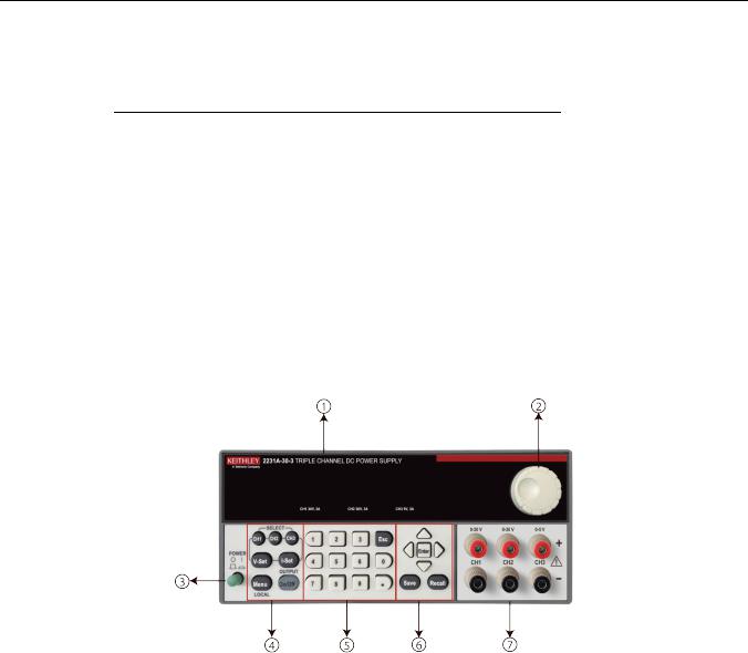
Front-panel overview
The front panel of Model 2231A-30-3 is shown below. Descriptions of the controls on the front panel follow the figure.
Figure 1: Model 2231A-30-3 front panel
Item |
Description |
|
|
1 |
Vacuum fluorescent display (VFD) |
2 |
Rotary knob |
3 |
POWER button |
4 |
Function buttons: Channel select buttons, V-Set (voltage setting), I-Set |
|
(current setting), Menu and Output On/OFF |
5 |
Numeric buttons and ESC button |
6 |
Up/Down/Left/Right arrow buttons, Enter button and Save/Recall function |
|
buttons |
7 |
Output terminals |
Section 2:Quick reference |
Model 2231A Triple-channel DC Power Supply Reference Manual |
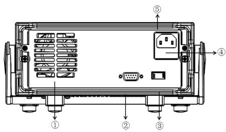
Rear panel overview
The rear panel of the Model 2231A-30-3 is shown below; descriptions follow the figure.
Figure 2: Model 2231A-30-3 rear panel
Item |
Description |
|
|
1 |
Ventilation holes |
2 |
TTL interface connector for remote control |
3 |
110 V/220 V AC power selection switch |
4 |
Fuse compartment |
5 |
AC power inlet |
Installing the system
This section contains information on how to install your Model 2231A-30-3 power supply.
•Unpack the instrument and check that you received all the items listed as standard accessories.
•Check that you also received any other accessories that you ordered with your instrument.
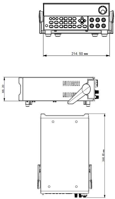
Dimensions
The dimensions of the Model 2231A-30-3 power supply: 214.5 mm wide × 88.2 mm high ×354.6 mm deep.
2-2 |
077100401/September 2014 |
Model 2231A-30-3 Triple-channel DC Power Supply Reference Manual |
Section 2:Quick reference |
Figure 3: Model 2231A front and rear panel dimensions
Figure 4: Model 2231A-30-3 top and side dimensions
Adjust the carrying handle
The handle can be adjusted to the position shown in the following figures.
Figure 5: Place the instrument with the handle under the bottom surface
077100401/September 2014 |
2-3 |

Section 2:Quick reference |
Model 2231A Triple-channel DC Power Supply Reference Manual |
Figure 6: Place the instrument standing on the handle
Figure 7: Adjust the handle in front of the front panel
Power the instrument on or off
Follow the procedure below to connect the Model 2231A-30-3 to line power and turn on the instrument. The Model 2231A-30-3 operates on two ranges: 110 V and 230 V at a frequency of 50 Hz or 60 Hz. You need to select the line voltage and frequency on the rear panel. Make sure the line voltage setting is compatible with the line voltage in your area.
The Model 2231A-30-3 must be turned on and allowed to warm up for at least one hour to achieve rated accuracies.
2-4 |
077100401/September 2014 |

Model 2231A-30-3 Triple-channel DC Power Supply Reference Manual |
Section 2:Quick reference |
The power cord supplied with the Model 2231A contains a separate protective earth (safety ground) wire for use with grounded outlets. When proper connections are made, the instrument chassis is connected to power-line ground through the ground wire in the power cord. In addition, a redundant protective earth connection is provided through a screw on the rear panel. This terminal should be connected to a known protective earth. In the event of a failure, not using a properly grounded protective earth and grounded outlet may result in personal injury or death due to electric shock.
Do not replace detachable mains supply cords with inadequately rated cords. Failure to use properly rated cords may result in personal injury or death due to electric shock.
To connect the power cord:
1.Make sure that the front panel POWER switch is in the off position.
2.Properly set the 110 V/220 V selector switch located on the rear panel.
3.Connect the female end of the supplied power cord to the AC receptacle on the rear panel.
4.Connect the other end of the power cord to a grounded AC outlet.
To turn a Model 2231A-30-3 on and off:
1.Disconnect any devices under test (DUTs) from the Model 2231A-30-3 before turning the instrument on.
2.To turn your instrument on, push the front-panel POWER switch to place it in the on position. The screen is displayed when power up is complete.
3.To turn your instrument off, Push the front-panel POWER switch to place it in the off position.
To avoid any fire or electric shock, please ensure the AC input voltage fluctuation does not exceed 10% of the working voltage range.
To satisfy safety requirements, always use load wires heavy enough that they will not overheat when carrying the maximum short-circuit output current of the power supply. If there is more than one load, then every pair of load wires must be capable of safely carrying the full-rated current of the power supply.
077100401/September 2014 |
2-5 |

Section 2:Quick reference |
Model 2231A Triple-channel DC Power Supply Reference Manual |
Self-test procedure
After the instrument is powered on, the screen displays the following information during the self-test process.
Initializing…
After 1 s, the screen displays the following information for about 2 s if the EEPROM test fails.
EEPROM Test Failure
If the last saved settings for the power supply are lost, the vacuum fluorescent display displays the following information for 2 seconds:
User Data Lost
During the channel scan, the screen displays the following information:
Scan Channels
If the channel data initialization fails, the screen displays the following information for 2 seconds:
Channel Initialization Failed
If the user calibration data in the EEPROM are lost, the screen displays the following information for 2 seconds:
Calibration Data Lost
2-6 |
077100401/September 2014 |

Model 2231A-30-3 Triple-channel DC Power Supply Reference Manual |
Section 2:Quick reference |
If the factory calibration data are lost, the screen displays the following information for 2 seconds:
Factory Calibration Data Lost
If no error occurs during the self-test, the screen should display as below: the first row is the output voltage of the 3 channels, and the second row is the current or the OFF status indicator.
10.00 V |
11.00 V |
3.00 V |
0.000 A |
0.000 A |
0.000 A |
Check the output
The following procedures verify that the power supply outputs its rated voltage and current and properly responds to operations from the front panel.
Voltage output check
To verify basic voltage function without a load, please follow these steps:
1.Remove all leads from the output connectors.
2.Turn on the power supply.
3.Push Menu. Default Set should appear on the display.
4.Push Enter to bring up the default settings menu. No and Yes should appear on the display.
5.Push the down arrow keys to select Yes. Push Enter to enable the default settings.
6.Push the front-panel On/Off button to turn on the outputs. The OFF messages on the display should be replaced by current readings and the CV indicators should turn on. The upper line of the display should show the actual output voltage.
7.Check that the front-panel voltmeter properly responds to the number buttons. First, select a channel using one of the channel select buttons. Push V-set, use the number buttons to set the voltage value to 0 and push Enter. Check if the displayed voltage value is approximately 0 V and check if the displayed current value is approximately 0 A. You can confirm the 0 V setting with a voltmeter.
8.Push V-set and use the numeric buttons and Enter button to set the voltage value to the maximum allowable for your power supply, as indicated on the unit's front-panel.
9.Check if the displayed voltage value is approximately the same value as the voltage setting.
10.Repeat steps 7 through 9 for each output channel.
077100401/September 2014 |
2-7 |
Section 2:Quick reference |
Model 2231A Triple-channel DC Power Supply Reference Manual |
Current output check
To verify the basic current functions when the power supply is short-circuited, please follow these steps:
1.Remove all leads from the output connectors.
2.Turn on the power supply.
3.Push Menu. Default Set should appear on the display.
4.Push Enter to bring up the default settings menu. No and Yes should appear on the display.
5.Push the down arrow keys to select Yes. Push Enter to enable the default settings.
6.Ensure that the output is disabled and the OFF indicator is shown for all channels. If needed, push the On/Off button to ensure that the outputs are disabled and the OFF messages are displayed.
7.Use an insulated test lead to connect a short across the (+) and (-) output terminals of the channel you will be testing.
Use a wire size sufficient to handle the maximum current.
To satisfy safety requirements, always use load wires heavy enough that they will not overheat when carrying the maximum short-circuit output current of the power supply. If there is more than one load, then every pair of load wires must be capable of safely carrying the full-rated current of the power supply.
8.Push the On/Off button to enable the outputs. The CC indicator should be on the channel with the shorted output.
9.Select a channel using one of the channel select buttons.
10.Push I-set and use the numeric buttons and the Enter button to set the current value to 0 A. Check if the displayed current value is approximately 0 A.
11.Push I-set and use the numeric buttons and the Enter button to set the current value to the maximum allowable for the output channel. Check if the displayed current value is approximately the same value as the maximum allowable.
12.Turn all outputs off by pushing the Output On/Off button. Note that the outputs are off when the display for all channels shows <OFF>.
13.Repeat steps 7 through 12 for each output channel.
14.Turn off the instrument and remove the short wire from the (+) and (-) output terminals.
What to do if the power supply does not turn on
To solve problems you might encounter when turning on the power supply, please follow these steps:
1. Verify that there is AC power applied to the power supply.
First, check that the AC power cord is firmly plugged in to the power connector on the rear-panel of the power supply. You should also make sure that the AC power source you plugged the power supply in to is energized. Then, check that the power supply is turned on.
2. Verify the power-line voltage setting.
2-8 |
077100401/September 2014 |

Model 2231A-30-3 Triple-channel DC Power Supply Reference Manual |
Section 2:Quick reference |
Make sure the voltage selector switch is set according to the present line voltage (110 VAC or 220 VAC) when the power supply is shipped from the factory. Change the voltage setting if it is incorrect.
3. Verify the correct power-line fuse is installed.
If the fuse is damaged, please see the table below to replace the fuse for your power supply.
Model |
Fuse Specifications |
|
|
|
|
2231A-30-3 |
3.15 A (220V AC) |
|
6.30 A (110V AC) |
||
|
4. If you need more help, contact Keithley.
077100401/September 2014 |
2-9 |
Loading...