


 Loading...
www.keithley.com
Model 2110 5½ Digit Multimeter
Calibration Manual
2110-905-01 Rev. C / August 2013
*P211090501C*
2110-905-01
A Greater Measure of Confidence
A Tektronix Company
Model 2110
5½ Digit Multimeter
Calibration Manual
© 2013, Keithley Instruments, Inc.
Cleveland, Ohio, U.S.A. All rights reserved.
Any unauthorized reproduction, photocopy, or use of the information herein, in whole or in part, without the prior written approval of Keithley Instruments, Inc. is strictly prohibited.
All Keithley Instruments product names are trademarks or registered trademarks of Keithley Instruments, Inc. Other brand names are trademarks or registered trademarks of their respective holders.
Document number: 2110-905-01 Rev. C / August 2013

Safety precautions
The following safety precautions should be observed before using this product and any associated instrumentation. Although some instruments and accessories would normally be used with nonhazardous voltages, there are situations where hazardous conditions may be present.
This product is intended for use by qualified personnel who recognize shock hazards and are familiar with the safety precautions required to avoid possible injury. Read and follow all installation, operation, and maintenance information carefully before using the product. Refer to the user documentation for complete product specifications.
If the product is used in a manner not specified, the protection provided by the product warranty may be impaired.
The types of product users are:
Responsible body is the individual or group responsible for the use and maintenance of equipment, for ensuring that the equipment is operated within its specifications and operating limits, and for ensuring that operators are adequately trained.
Operators use the product for its intended function. They must be trained in electrical safety procedures and proper use of the instrument. They must be protected from electric shock and contact with hazardous live circuits.
Maintenance personnel perform routine procedures on the product to keep it operating properly, for example, setting the line voltage or replacing consumable materials. Maintenance procedures are described in the user documentation. The procedures explicitly state if the operator may perform them. Otherwise, they should be performed only by service personnel.
Service personnel are trained to work on live circuits, perform safe installations, and repair products. Only properly trained service personnel may perform installation and service procedures.
Keithley Instruments products are designed for use with electrical signals that are measurement, control, and data I/O connections, with low transient overvoltages, and must not be directly connected to mains voltage or to voltage sources with high transient overvoltages. Measurement Category II (as referenced in IEC 60664) connections require protection for high transient overvoltages often associated with local AC mains connections. Certain Keithley measuring instruments may be connected to mains. These instruments will be marked as category II or higher.
Unless explicitly allowed in the specifications, operating manual, and instrument labels, do not connect any instrument to mains.
Exercise extreme caution when a shock hazard is present. Lethal voltage may be present on cable connector jacks or test fixtures. The American National Standards Institute (ANSI) states that a shock hazard exists when voltage levels greater than 30 V RMS, 42.4 V peak, or 60 VDC are present. A good safety practice is to expect that hazardous voltage is present in any unknown circuit before measuring.
Operators of this product must be protected from electric shock at all times. The responsible body must ensure that operators are prevented access and/or insulated from every connection point. In some cases, connections must be exposed to potential human contact. Product operators in these circumstances must be trained to protect themselves from the risk of electric shock. If the circuit is capable of operating at or above 1000 V, no conductive part of the circuit may be exposed.
Do not connect switching cards directly to unlimited power circuits. They are intended to be used with impedance-limited sources. NEVER connect switching cards directly to AC mains. When connecting sources to switching cards, install protective devices to limit fault current and voltage to the card.
Before operating an instrument, ensure that the line cord is connected to a properly-grounded power receptacle. Inspect the connecting cables, test leads, and jumpers for possible wear, cracks, or breaks before each use.
When installing equipment where access to the main power cord is restricted, such as rack mounting, a separate main input power disconnect device must be provided in close proximity to the equipment and within easy reach of the operator.
For maximum safety, do not touch the product, test cables, or any other instruments while power is applied to the circuit under test. ALWAYS remove power from the entire test system and discharge any capacitors before: connecting or disconnecting cables or jumpers, installing or removing switching cards, or making internal changes, such as installing or removing jumpers.
Do not touch any object that could provide a current path to the common side of the circuit under test or power line (earth) ground. Always make measurements with dry hands while standing on a dry, insulated surface capable of withstanding the voltage being measured.
For safety, instruments and accessories must be used in accordance with the operating instructions. If the instruments or accessories are used in a manner not specified in the operating instructions, the protection provided by the equipment may be
impaired.
Do not exceed the maximum signal levels of the instruments and accessories, as defined in the specifications and operating information, and as shown on the instrument or test fixture panels, or switching card.
When fuses are used in a product, replace with the same type and rating for continued protection against fire hazard.
Chassis connections must only be used as shield connections for measuring circuits, NOT as protective earth (safety ground) connections.
If you are using a test fixture, keep the lid closed while power is applied to the device under test. Safe operation requires the use of a lid interlock.
If a  screw is present, connect it to protective earth (safety ground) using the wire recommended in the user documentation.
The  symbol on an instrument means caution, risk of danger. The user must refer to the operating instructions located in the user documentation in all cases where the symbol is marked on the instrument.
The  symbol on an instrument means caution, risk of electric shock. Use standard safety precautions to avoid personal contact with these voltages.
The  symbol on an instrument shows that the surface may be hot. Avoid personal contact to prevent burns. The
  symbol indicates a connection terminal to the equipment frame.
If this  symbol is on a product, it indicates that mercury is present in the display lamp. Please note that the lamp must be properly disposed of according to federal, state, and local laws.
The WARNING heading in the user documentation explains dangers that might result in personal injury or death. Always read the associated information very carefully before performing the indicated procedure.
The CAUTION heading in the user documentation explains hazards that could damage the instrument. Such damage may invalidate the warranty.
Instrumentation and accessories shall not be connected to humans.
Before performing any maintenance, disconnect the line cord and all test cables.
To maintain protection from electric shock and fire, replacement components in mains circuits — including the power transformer, test leads, and input jacks — must be purchased from Keithley Instruments. Standard fuses with applicable national safety approvals may be used if the rating and type are the same. Other components that are not safety-related may be purchased from other suppliers as long as they are equivalent to the original component (note that selected parts should be purchased only through Keithley Instruments to maintain accuracy and functionality of the product). If you are unsure about the applicability of a replacement component, call a Keithley Instruments office for information.
To clean an instrument, use a damp cloth or mild, water-based cleaner. Clean the exterior of the instrument only. Do not apply cleaner directly to the instrument or allow liquids to enter or spill on the instrument. Products that consist of a circuit board with no case or chassis (e.g., a data acquisition board for installation into a computer) should never require cleaning if handled according to instructions. If the board becomes contaminated and operation is affected, the board should be returned to the factory for proper cleaning/servicing.
Safety precaution revision of January 2013.
|
Table of Contents |
Calibrating and adjusting the Model 2110............................................................... |
1-1 |
Introduction .......................................................................................................................... |
1-1 |
Control software ................................................................................................................... |
1-1 |
Environmental conditions ..................................................................................................... |
1-3 |
Calibration considerations.................................................................................................... |
1-3 |
Recommended test equipment ............................................................................................ |
1-4 |
Calibration code ................................................................................................................... |
1-4 |
Adjustment................................................................................................................ |
2-1 |
Voltage function adjustment (DC and AC) ........................................................................... |
2-1 |
DCV range adjustment.............................................................................................................. |
2-1 |
ACV range adjustment .............................................................................................................. |
2-4 |
Frequency range adjustment..................................................................................................... |
2-5 |
Ohms function adjustment ................................................................................................... |
2-6 |
Ohms, low range adjustment (100Ω - 10MΩ) 2 wire................................................................. |
2-6 |
Ohms, low range adjustment (100Ω - 10MΩ) 4 wire................................................................. |
2-9 |
Ohms, high range adjustment (100 MΩ)................................................................................. |
2-11 |
Current function adjustment (DC and AC) ......................................................................... |
2-12 |
DC current range adjustment .................................................................................................. |
2-12 |
DC high current adjustment..................................................................................................... |
2-13 |
AC current range adjustment .................................................................................................. |
2-14 |
AC high current adjustment..................................................................................................... |
2-15 |
Temperature function adjustment ...................................................................................... |
2-16 |
Capacitance function adjustment....................................................................................... |
2-16 |
Calibration date .................................................................................................................. |
2-18 |
Performance verification.......................................................................................... |
3-1 |
Performing accuracy verification.......................................................................................... |
3-1 |
DC voltage accuracy verification............................................................................................... |
3-1 |
AC voltage accuracy verification ............................................................................................... |
3-2 |
Resistance accuracy verification............................................................................................... |
3-3 |
DC current accuracy verification ............................................................................................... |
3-3 |
AC current accuracy verification................................................................................................ |
3-4 |
Frequency accuracy verification................................................................................................ |
3-4 |
Temperature accuracy verification ............................................................................................ |
3-5 |
Capacitance accuracy verification............................................................................................. |
3-5 |

Section 1
Calibrating and adjusting the Model 2110
In this section:
Introduction .............................................................................. |
1-1 |
Control software....................................................................... |
1-1 |
Environmental conditions ......................................................... |
1-3 |
Calibration considerations........................................................ |
1-3 |
Recommended test equipment ................................................ |
1-4 |
Calibration code ....................................................................... |
1-4 |
Introduction
This manual provides calibration and verification procedures for the Keithley Instruments Model 2110 5-1/2-Digit Multimeter. The procedures are performed using remote programming (SCPI commands) over the USB interface using the KI-Tool software.
Control software
You must have one of the following items installed on the remote interface in order to obtain the proper VISA layer:
Keithley I/O Layer 5.0 or greater (included on the CD-ROM that came with your Model 2110)
NI-VISA 3.1 or greater
Agilent I/O Library Suite 14.2 or greater
1.Install the USB device driver and KI-Tool software from the Keithley Instruments Model 2110 Product Information CD.
2.Connect the Model 2110 to the USB port and launch the KI-Tool software.
3.Verify that correct model number is displayed in the upper right-hand corner of the tool. See Figure 1 for details.
4.Test the communications link between the Model 2110 and the control software by clicking several function buttons and verify that the Model 2110 responds accordingly. See the figure below for more details.

Section 1: Calibrating and adjusting the Model 2110 |
Model 2110 5½ Digit Multimeter Calibration Manual |
Figure 1: Model 2110 KI-TOOL software
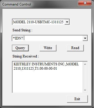
5.The procedure consists of connecting the Fluke 5700A/5725A and 5520A/5522A output to the Model 2110 front panel input, setting up appropriate ranges, and performing calibration by sending specific SCPI commands. These commands are entered into the Send String field followed by clicking the Write button. To access the command control window, click Tool > Command Control.
The figure below shows the Command Control window. Ensure that the correct model number is selected before sending any SCPI commands.
1-2 |
2110-905-01 Rev. C / August 2013 |
Model 2110 5½ Digit Multimeter Calibration Manual |
Section 1: Calibrating and adjusting the Model 2110 |
Figure 2: Command Control window
Environmental conditions
Perform the calibration procedures in an environment that has:
•An ambient temperature of 18 °C to 28 °C
•A relative humidity of less than 80 percent unless otherwise noted.
Calibration considerations
When performing the calibration procedure:
•Make sure that the equipment is properly warmed up and connected to the appropriate input jacks.
•Make sure the calibrator is in OPERATE before you complete each calibration step.
•Do not connect test equipment to the Model 2110 through a scanner or other switching equipment.
•If an error occurs during calibration, the Model 2110 will generate an appropriate error message. Please refer to The Model 2110 Reference Manual for error code descriptions.
•During the adjustment process, the Model 2110 may not display the correct amplitude of the applied signal. This condition is normal.
•After the adjustment procedures are completed, perform the performance verification in Section 3 to verify that the Model 2110 is within manufacturer’s specifications.
2110-905-01 Rev. C / August 2013 |
1-3 |
Section 1: Calibrating and adjusting the Model 2110 |
Model 2110 5½ Digit Multimeter Calibration Manual |
Recommended test equipment
Use the Fluke 5700A Calibrator and the Fluke 5725A Amplifier (or the equivalent or better) and the Fluke 5520A/5522A for temperature and capacitance to calibrate the Model 2110.
Calibration code
To unlock and initiate calibration:
1.Unlock calibration by sending the following command: CAL:PROT:CODE <up to 8-character string>
The default command is:
CAL:PROT:CODE 123456
2.Initiate calibration by sending the following command:
CAL:PROT:INIT
1-4 |
2110-905-01 Rev. C / August 2013 |
Loading...