


www.tek.com/keithley 
Model 2182/2182A Nanovoltmeter
User’s Manual
2182A-900-01 Rev. B / May 2017

WARRANTY
Keithley Instruments warrants this product to be free from defects in material and workmanship for a period of one (1) year from date of shipment.
Keithley Instruments warrants the following items for 90 days from the date of shipment: probes, cables, software, rechargeable batteries, diskettes, and documentation.
During the warranty period, Keithley Instruments will, at its option, either repair or replace any product that proves to be defective.
To exercise this warranty, write or call your local Keithley Instruments representative, or contact Keithley Instruments headquarters in Cleveland, Ohio. You will be given prompt assistance and return instructions. Send the product, transportation prepaid, to the indicated service facility. Repairs will be made and the product returned, transportation prepaid. Repaired or replaced products are warranted for the balance of the original warranty period, or at least 90 days.
LIMITATION OF WARRANTY
This warranty does not apply to defects resulting from product modification without Keithley Instruments’ express written consent, or misuse of any product or part. This warranty also does not apply to fuses, software, non-rechargeable batteries, damage from battery leakage, or problems arising from normal wear or failure to follow instructions.
THIS WARRANTY IS IN LIEU OF ALL OTHER WARRANTIES, EXPRESSED OR IMPLIED, INCLUDING ANY IMPLIED WARRANTY OF MERCHANTABILITY OR FITNESS FOR A PARTICULAR USE. THE REMEDIES PROVIDED HEREIN ARE THE BUYER’S SOLE AND EXCLUSIVE REMEDIES.
NEITHER KEITHLEY INSTRUMENTS NOR ANY OF ITS EMPLOYEES SHALL BE LIABLE FOR ANY DIRECT, INDIRECT, SPECIAL, INCIDENTAL, OR CONSEQUENTIAL DAMAGES ARISING OUT OF THE USE OF ITS INSTRUMENTS AND SOFTWARE, EVEN IF KEITHLEY INSTRUMENTS HAS BEEN ADVISED IN ADVANCE OF THE POSSIBILITY OF SUCH DAMAGES. SUCH EXCLUDED DAMAGES SHALL INCLUDE, BUT ARE NOT LIMITED TO: COST OF REMOVAL AND INSTALLATION, LOSSES SUSTAINED AS THE RESULT OF INJURY TO ANY PERSON, OR DAMAGE TO PROPERTY.
Keithley Instruments
Corporate Headquarters • 28775 Aurora Road • Cleveland, Ohio 44139 440-248-0400 • Fax: 440-248-6168 • 1-800-KEITHLEY (1-800-935-5595) • www.tek.com/keithley
3/07

Model 2182 and 2182A Nanovoltmeter
User’s Manual
This User’s Manual supports both the Models 2182 and 2182A:
References to the Model 2182 apply to both the Models 2182 and 2182A.
References to the Model 2182/2182A apply to the Model 2182 with firmaware version A10 or higher, and the Model 2182A with firmware version C01 or higher.
References to the Model 2182A applies to the Model 2182A with firmware version C01 or higher.
©2017, Keithley Instruments
All rights reserved.
Cleveland, Ohio, U.S.A.
First Printing, June 2004
Document Number: 2182A-900-01 Rev. B

Manual Print History
The print history shown below lists the printing dates of all Revisions and Addenda created for this manual. The Revision Level letter increases alphabetically as the manual undergoes subsequent updates. Addenda, which are released between Revisions, contain important change information that the user should incorporate immediately into the manual. Addenda are numbered sequentially. When a new Revision is created, all Addenda associated with the previous Revision of the manual are incorporated into the new Revision of the manual. Each new Revision includes a revised copy of this print history page.
Revision A (Document Number 2182A-900-01) ............................................................. |
June 2004 |
Revision B (Document Number 2182A-900-01) ............................................................. |
May 2017 |
All Keithley product names are trademarks or registered trademarks of Keithley Instruments. Other brand names are trademarks or registered trademarks of their respective holders.

Safety Precautions
The following safety precautions should be observed before using this product and any associated instrumentation. Although some instruments and accessories would normally be used with non-hazardous voltages, there are situations where hazardous conditions may be present.
This product is intended for use by qualified personnel who recognize shock hazards and are familiar with the safety precautions required to avoid possible injury. Read and follow all installation, operation, and maintenance information carefully before using the product. Refer to the user documentation for complete product specifications.
If the product is used in a manner not specified, the protection provided by the product warranty may be impaired. The types of product users are:
Responsible body is the individual or group responsible for the use and maintenance of equipment, for ensuring that the equipment is operated within its specifications and operating limits, and for ensuring that operators are adequately trained.
Operators use the product for its intended function. They must be trained in electrical safety procedures and proper use of the instrument. They must be protected from electric shock and contact with hazardous live circuits.
Maintenance personnel perform routine procedures on the product to keep it operating properly, for example, setting the line voltage or replacing consumable materials. Maintenance procedures are described in the user documentation. The procedures explicitly state if the operator may perform them. Otherwise, they should be performed only by service personnel.
Service personnel are trained to work on live circuits, perform safe installations, and repair products. Only properly trained service personnel may perform installation and service procedures.
Keithley Instruments products are designed for use with electrical signals that are rated Measurement Category I and Measurement Category II, as described in the International Electrotechnical Commission (IEC) Standard IEC 60664. Most measurement, control, and data I/O signals are Measurement Category I and must not be directly connected to mains voltage or to voltage sources with high transient over-voltages. Measurement Category II connections require protection for high transient over-voltages often associated with local AC mains connections. Assume all measurement, control, and data I/O connections are for connection to Category I sources unless otherwise marked or described in the user documentation.
Exercise extreme caution when a shock hazard is present. Lethal voltage may be present on cable connector jacks or test fixtures. The American National Standards Institute (ANSI) states that a shock hazard exists when voltage levels greater than 30V RMS, 42.4V peak, or 60VDC are present. A good safety practice is to expect that hazardous voltage is present in any unknown circuit before measuring.
Operators of this product must be protected from electric shock at all times. The responsible body must ensure that operators are prevented access and/or insulated from every connection point. In some cases, connections must be exposed to potential human contact. Product operators in these circumstances must be trained to protect themselves from the risk of electric shock. If the circuit is capable of operating at or above 1000 volts, no conductive part of the circuit may be exposed.
Do not connect switching cards directly to unlimited power circuits. They are intended to be used with impedancelimited sources. NEVER connect switching cards directly to AC mains. When connecting sources to switching cards, install protective devices to limit fault current and voltage to the card.
Before operating an instrument, make sure the line cord is connected to a properly grounded power receptacle. Inspect the connecting cables, test leads, and jumpers for possible wear, cracks, or breaks before each use.
When installing equipment where access to the main power cord is restricted, such as rack mounting, a separate main input power disconnect device must be provided in close proximity to the equipment and within easy reach of the operator.
11/07

For maximum safety, do not touch the product, test cables, or any other instruments while power is applied to the circuit under test. ALWAYS remove power from the entire test system and discharge any capacitors before: connecting or disconnecting cables or jumpers, installing or removing switching cards, or making internal changes, such as installing or removing jumpers.
Do not touch any object that could provide a current path to the common side of the circuit under test or power line (earth) ground. Always make measurements with dry hands while standing on a dry, insulated surface capable of withstanding the voltage being measured.
The instrument and accessories must be used in accordance with specifications and operating instructions, or the safety of the equipment may be impaired.
Do not exceed the maximum signal levels of the instruments and accessories, as defined in the specifications and operating information, and as shown on the instrument or test fixture panels, or switching card.
When fuses are used in a product, replace with the same type and rating for continued protection against fire hazard.
Chassis connections must only be used as shield connections for measuring circuits, NOT as safety earth ground connections.
If you are using a test fixture, keep the lid closed while power is applied to the device under test. Safe operation requires the use of a lid interlock.
If a  screw is present, connect it to safety earth ground using the wire recommended in the user documentation.
The ! symbol on an instrument indicates that the user should refer to the operating instructions located in the documentation.
The  symbol on an instrument shows that it can source or measure 1000 volts or more, including the combined effect of normal and common mode voltages. Use standard safety precautions to avoid personal contact with these voltages.
The  symbol on an instrument shows that the surface may be hot. Avoid personal contact to prevent burns.
The 

 symbol indicates a connection terminal to the equipment frame.
If this  symbol is on a product, it indicates that mercury is present in the display lamp. Please note that the lamp must be properly disposed of according to federal, state, and local laws.
The WARNING heading in the user documentation explains dangers that might result in personal injury or death. Always read the associated information very carefully before performing the indicated procedure.
The CAUTION heading in the user documentation explains hazards that could damage the instrument. Such damage may invalidate the warranty.
Instrumentation and accessories shall not be connected to humans.
Before performing any maintenance, disconnect the line cord and all test cables.
To maintain protection from electric shock and fire, replacement components in mains circuits - including the power transformer, test leads, and input jacks - must be purchased from Keithley Instruments. Standard fuses with applicable national safety approvals may be used if the rating and type are the same. Other components that are not safety-related may be purchased from other suppliers as long as they are equivalent to the original component (note that selected parts should be purchased only through Keithley Instruments to maintain accuracy and functionality of the product). If you are unsure about the applicability of a replacement component, call a Keithley Instruments office for information.
To clean an instrument, use a damp cloth or mild, water-based cleaner. Clean the exterior of the instrument only. Do not apply cleaner directly to the instrument or allow liquids to enter or spill on the instrument. Products that consist of a circuit board with no case or chassis (e.g., data acquisition board for installation into a computer) should never require cleaning if handled according to instructions. If the board becomes contaminated and operation is affected, the board should be returned to the factory for proper cleaning/servicing.

Table of Contents
1 |
Getting Started |
|
|
General information ................................................................................................ |
1-3 |
|
Warranty information ....................................................................................... |
1-3 |
|
Contact information ......................................................................................... |
1-3 |
|
Safety symbols and terms ................................................................................ |
1-3 |
|
Inspection ......................................................................................................... |
1-3 |
|
Options and accessories ................................................................................... |
1-4 |
|
Nanovoltmeter features ........................................................................................... |
1-6 |
|
Front and rear panel familiarization ........................................................................ |
1-7 |
|
Front panel summary ....................................................................................... |
1-7 |
|
Rear panel summary ...................................................................................... |
1-11 |
|
Cleaning input connectors ..................................................................................... |
1-13 |
|
Power-Up .............................................................................................................. |
1-14 |
|
Line power connection ................................................................................... |
1-14 |
|
Setting line voltage and replacing fuse .......................................................... |
1-15 |
|
Power-up sequence ........................................................................................ |
1-15 |
|
Line frequency ............................................................................................... |
1-16 |
|
Display .................................................................................................................. |
1-16 |
|
Status and error messages .............................................................................. |
1-16 |
|
Default settings ..................................................................................................... |
1-16 |
2 |
Voltage and Temperature Measurements |
|
|
Measurement overview ........................................................................................... |
2-3 |
|
Voltage measurements ..................................................................................... |
2-3 |
|
Temperature measurements ............................................................................. |
2-3 |
|
Performance considerations .................................................................................... |
2-5 |
|
Warm-up .......................................................................................................... |
2-5 |
|
ACAL (calibration) .......................................................................................... |
2-5 |
|
Autozeroing modes .......................................................................................... |
2-6 |
|
LSYNC (line cycle synchronization) ............................................................... |
2-8 |
|
Pumpout current (low charge injection mode) ................................................. |
2-9 |
|
SCPI programming - ACAL, Front Autozero, Autozero, LSYNC, and |
|
|
Low Charge Injection .................................................................................. |
2-10 |
|
Connections ........................................................................................................... |
2-12 |
|
Connection techniques ................................................................................... |
2-12 |
|
Voltage only connections ............................................................................... |
2-14 |
|
Temperature only connections ....................................................................... |
2-15 |
|
Voltage and temperature connections ............................................................ |
2-16 |
|
Cleaning test circuit connectors ..................................................................... |
2-17 |

|
Temperature configuration ................................................................................... |
2-18 |
|
Measuring voltage and temperature ..................................................................... |
2-19 |
|
SCPI programming - voltage and temperature measurements ...................... |
2-20 |
|
Low-level considerations ...................................................................................... |
2-22 |
|
Thermal EMFs ............................................................................................... |
2-22 |
|
Noise .............................................................................................................. |
2-22 |
|
Applications .......................................................................................................... |
2-23 |
|
Low-resistance measurements ....................................................................... |
2-23 |
|
Standard cell comparisons ............................................................................. |
2-26 |
|
Heated Zener Reference and Josephson Junction Array comparisons .......... |
2-27 |
3 |
Range, Digits, Rate, and Filter |
|
|
Range ...................................................................................................................... |
3-3 |
|
Maximum readings .......................................................................................... |
3-3 |
|
Manual ranging ............................................................................................... |
3-3 |
|
Autoranging ..................................................................................................... |
3-4 |
|
SCPI programming - range ............................................................................. |
3-4 |
|
Digits ...................................................................................................................... |
3-5 |
|
SCPI programming - digits ............................................................................. |
3-5 |
|
Rate ......................................................................................................................... |
3-6 |
|
SCPI programming - rate ................................................................................ |
3-7 |
|
Filter ....................................................................................................................... |
3-8 |
|
Analog filter .................................................................................................... |
3-8 |
|
Digital filter ..................................................................................................... |
3-8 |
|
SCPI programming - filter ............................................................................. |
3-12 |
4 |
Relative, mX+b, and Percent (%) |
|
|
Relative ................................................................................................................... |
4-3 |
|
REL Key .......................................................................................................... |
4-3 |
|
SCPI programming - relative ......................................................................... |
4-4 |
|
mX+b and percent (%) ........................................................................................... |
4-6 |
|
mX+b ............................................................................................................... |
4-6 |
|
Percent (%) ...................................................................................................... |
4-7 |
|
SCPI programming - mX+b and percent ......................................................... |
4-8 |
5 |
Ratio and Delta |
|
|
Ratio ....................................................................................................................... |
5-2 |
|
Basic procedure ............................................................................................... |
5-2 |
|
Filter, Rel, and Ranging considerations .......................................................... |
5-4 |
|
Delta ....................................................................................................................... |
5-6 |
|
Selecting Delta ................................................................................................ |
5-9 |
|
Delta measurement procedure using a SourceMeter ....................................... |
5-9 |
|
Filter considerations ...................................................................................... |
5-15 |

|
SCPI programming - ratio and delta ..................................................................... |
5-16 |
|
Programming examples ................................................................................. |
5-16 |
|
Applications .......................................................................................................... |
5-18 |
|
Testing superconductor materials .................................................................. |
5-19 |
6 |
Buffer |
|
|
Buffer operations ..................................................................................................... |
6-2 |
|
Store ................................................................................................................. |
6-2 |
|
Recall ............................................................................................................... |
6-3 |
|
Buffer statistics ................................................................................................ |
6-4 |
|
SCPI programming - buffer .................................................................................... |
6-5 |
|
Programming example ..................................................................................... |
6-6 |
7 |
Triggering |
|
|
Trigger model .......................................................................................................... |
7-3 |
|
Idle ................................................................................................................... |
7-3 |
|
Control source and event detection .................................................................. |
7-4 |
|
Delay ................................................................................................................ |
7-4 |
|
Device action ................................................................................................... |
7-5 |
|
Output trigger ................................................................................................... |
7-5 |
|
Reading hold (autosettle) ........................................................................................ |
7-6 |
|
Hold example ................................................................................................... |
7-6 |
|
External triggering .................................................................................................. |
7-7 |
|
External trigger ................................................................................................ |
7-8 |
|
Voltmeter complete .......................................................................................... |
7-8 |
|
External triggering example ............................................................................. |
7-9 |
|
External triggering with BNC connections .................................................... |
7-12 |
|
SCPI programming - triggering ............................................................................ |
7-13 |
|
Trigger model (remote operation) .................................................................. |
7-13 |
|
Trigger model operation ................................................................................ |
7-15 |
|
Triggering commands .................................................................................... |
7-16 |
|
Programming example ................................................................................... |
7-17 |
8 |
Limits |
|
|
Limit operations ...................................................................................................... |
8-3 |
|
Setting limit values .......................................................................................... |
8-4 |
|
Enabling limits ................................................................................................. |
8-4 |
|
SCPI programming - limits ..................................................................................... |
8-5 |
|
Application .............................................................................................................. |
8-7 |
|
Sorting resistors ............................................................................................... |
8-7 |

9 |
Stepping and Scanning |
|
|
Step/Scan overview ................................................................................................ |
9-3 |
|
Internal Stepping/Scanning (Channels 1 and 2) .............................................. |
9-3 |
|
External Stepping/Scanning ............................................................................ |
9-3 |
|
Front panel trigger models ...................................................................................... |
9-4 |
|
Internal scanning ............................................................................................. |
9-4 |
|
Other Stepping/Scanning operations ............................................................... |
9-6 |
|
Stepping/Scanning controls .................................................................................... |
9-6 |
|
Step/Scan configuration .................................................................................. |
9-7 |
|
Stepping/Scanning examples .................................................................................. |
9-8 |
|
Internal scanning ............................................................................................. |
9-8 |
|
Internal stepping .............................................................................................. |
9-9 |
|
External scanning .......................................................................................... |
9-10 |
|
SCPI programming - stepping and scanning ........................................................ |
9-12 |
|
Programming example .................................................................................. |
9-13 |
|
Application — I-V curves using internal scan ..................................................... |
9-14 |
|
SCAN for IV curves [Measure V, sweep I, constant H (magnetic field) |
|
|
or T (temperature)] ..................................................................................... |
9-14 |
10 |
Analog Output |
|
|
Overview .............................................................................................................. |
10-3 |
|
Operation .............................................................................................................. |
10-5 |
|
Analog output connections ............................................................................ |
10-5 |
|
Configure and control analog output ............................................................. |
10-5 |
|
Analog output rel ........................................................................................... |
10-5 |
|
SCPI programming - analog output ...................................................................... |
10-6 |
|
Programming example .................................................................................. |
10-6 |
11 |
Remote Operation |
|
|
Selecting and configuring an interface ................................................................. |
11-3 |
|
Interfaces ....................................................................................................... |
11-3 |
|
Languages ...................................................................................................... |
11-3 |
|
Interface selection and configuration procedures .......................................... |
11-4 |
|
GPIB operation and reference .............................................................................. |
11-6 |
|
GPIB bus standards ....................................................................................... |
11-6 |
|
GPIB bus connections ................................................................................... |
11-6 |
|
Primary address selection .............................................................................. |
11-8 |
|
QuickBASIC programming ........................................................................... |
11-8 |
|
General bus commands ................................................................................. |
11-9 |
|
Front panel GPIB operation ........................................................................ |
11-12 |
|
Status structure ............................................................................................ |
11-13 |
|
Programming syntax ................................................................................... |
11-21 |
|
RS-232 interface reference .................................................................................. |
11-27 |
|
Sending and receiving data .......................................................................... |
11-27 |
|
Baud rate, flow control and terminator ........................................................ |
11-27 |
|
RS-232 connections ..................................................................................... |
11-29 |
|
Error messages ............................................................................................. |
11-30 |
12 |
Common Commands |
|
|
*CLS — Clear Status Clear status registers and error queue ........................ |
12-3 |
|
*ESE <NRf> – Event Enable Program the standard event enable register ... |
12-4 |
|
*ESE? – Event Enable Query Read the standard event register .................... |
12-4 |
|
*ESR? – Event Status Register Query Read register and clear it .................. |
12-6 |
|
*IDN? – Identification Query Read the identification code .......................... |
12-7 |
|
*OPC – Operation Complete Set the OPC bit in the standard |
|
|
event register after all pending commands are complete ............................ |
12-8 |
|
*OPC? – Operation Complete Query Place a “1” in the output |
|
|
queue after all pending operations are completed ..................................... |
12-10 |
|
*RCL – Recall Return to setup stored in memory ....................................... |
12-11 |
|
*RST – Reset Return 2182 to *RST defaults .............................................. |
12-12 |
|
*SAV – Save Save present setup in memory ............................................... |
12-12 |
|
*SRE <NRf> – Service Request Enable Program service request |
|
|
enable register ........................................................................................... |
12-12 |
|
*SRE? – Service Request Enable Query Read service request |
|
|
enable register ........................................................................................... |
12-12 |
|
*STB? – Status Byte Query Read status byte register ................................. |
12-14 |
|
*TRG – Trigger Send bus trigger to 2182 ................................................... |
12-15 |
|
*TST?– Self-Test Query Run self test and read result ................................ |
12-15 |
|
*WAI – Wait-to-Continue Prevent execution of commands until |
|
|
previous commands are completed ........................................................... |
12-16 |
13 |
SCPI Signal Oriented Measurement Commands |
|
|
:CONFigure:<function> ................................................................................. |
13-2 |
|
:FETCh? ......................................................................................................... |
13-3 |
|
:READ? .......................................................................................................... |
13-3 |
|
:MEASure:<function>? ................................................................................. |
13-4 |
14 |
SCPI Reference Tables |

15 |
Additional SCPI Commands |
|
|
DISPlay subsystem ............................................................................................... |
15-3 |
|
:TEXT commands ......................................................................................... |
15-3 |
|
FORMat subsystem .............................................................................................. |
15-4 |
|
:DATA command .......................................................................................... |
15-4 |
|
:BORDer command ....................................................................................... |
15-6 |
|
:ELEMents command .................................................................................... |
15-6 |
|
STATus subsystem ............................................................................................... |
15-7 |
|
[:EVENt]? command .................................................................................... |
15-7 |
|
:ENABle command ..................................................................................... |
15-11 |
|
:CONDition? command ............................................................................... |
15-13 |
|
:PRESet command ....................................................................................... |
15-14 |
|
:QUEue commands ..................................................................................... |
15-14 |
|
:SYSTem subsystem ........................................................................................... |
15-16 |
|
:PRESet command ....................................................................................... |
15-16 |
|
Performance commands .............................................................................. |
15-16 |
|
:BEEPer command ...................................................................................... |
15-18 |
|
:KCLick command ...................................................................................... |
15-18 |
|
:POSetup <name> command ...................................................................... |
15-18 |
|
:VERSion? command .................................................................................. |
15-19 |
|
:ERRor? command ...................................................................................... |
15-19 |
|
:CLEar command ........................................................................................ |
15-19 |
|
:KEY <NRf> command ............................................................................. |
15-20 |
ASpecifications
BStatus and Error Messages
CMeasurement Considerations
Measurement considerations .................................................................................. |
C-2 |
Thermoelectric potentials ................................................................................ |
C-2 |
Thermoelectric generation ............................................................................... |
C-3 |
Source resistance noise .................................................................................... |
C-4 |
Magnetic fields ................................................................................................ |
C-6 |
Radio frequency interference .......................................................................... |
C-6 |
Ground loops ................................................................................................... |
C-6 |
Shielding .......................................................................................................... |
C-8 |
Meter loading .................................................................................................. |
C-9 |

DModel 182 Emulation Commands
EExample Programs
|
Program examples .................................................................................................. |
E-2 |
|
Changing function and range .......................................................................... |
E-2 |
|
One-shot triggering ......................................................................................... |
E-4 |
|
Generating SRQ on buffer full ........................................................................ |
E-5 |
|
Storing readings in buffer ............................................................................... |
E-6 |
|
Taking readings using the :READ? command ................................................ |
E-7 |
|
Controlling the Model 2182 via the RS-232 COM2 port ............................... |
E-8 |
F |
IEEE-488 Bus Overview |
|
|
Introduction ............................................................................................................. |
F-2 |
|
Bus description ........................................................................................................ |
F-2 |
|
Bus lines .................................................................................................................. |
F-4 |
|
Data lines ......................................................................................................... |
F-4 |
|
Bus management lines ..................................................................................... |
F-4 |
|
Handshake lines ............................................................................................... |
F-5 |
|
Bus commands ........................................................................................................ |
F-6 |
|
Uniline commands ........................................................................................... |
F-7 |
|
Universal multiline commands ........................................................................ |
F-8 |
|
Addressed multiline commands ....................................................................... |
F-9 |
|
Address commands .......................................................................................... |
F-9 |
|
Unaddress commands ...................................................................................... |
F-9 |
|
Common commands ...................................................................................... |
F-10 |
|
SCPI commands ............................................................................................. |
F-10 |
|
Command codes ............................................................................................. |
F-10 |
|
Typical command sequences ......................................................................... |
F-11 |
|
IEEE command groups .................................................................................. |
F-12 |
|
Interface function codes ........................................................................................ |
F-13 |
G |
IEEE-488 and SCPI Conformance Information |
|
|
Introduction ............................................................................................................ |
G-2 |
H |
Measurement Queries |
|
|
:FETCh? ................................................................................................................. |
H-2 |
|
What it does .................................................................................................... |
H-2 |
|
Limitations ...................................................................................................... |
H-2 |
|
Where appropriate ........................................................................................... |
H-2 |
|
:READ? .................................................................................................................. |
H-2 |
|
What it does .................................................................................................... |
H-2 |
|
Limitations ...................................................................................................... |
H-3 |
|
When appropriate ............................................................................................ |
H-3 |

|
:MEASure[:<function>]? ...................................................................................... |
H-3 |
|
What it does .................................................................................................... |
H-3 |
|
Limitations ..................................................................................................... |
H-3 |
|
When appropriate ........................................................................................... |
H-3 |
|
[:SENSe[1]]:DATA:FRESh? ................................................................................ |
H-4 |
|
What it does .................................................................................................... |
H-4 |
|
Limitations ..................................................................................................... |
H-4 |
|
When appropriate ........................................................................................... |
H-4 |
|
[:SENSe[1]]:DATA[:LATest]? ............................................................................. |
H-4 |
|
What it does .................................................................................................... |
H-4 |
|
Limitations ..................................................................................................... |
H-4 |
|
When appropriate ........................................................................................... |
H-4 |
|
Examples ............................................................................................................... |
H-5 |
|
One-shot reading, DC volts, no trigger, fastest rate ....................................... |
H-5 |
|
One-shot reading, DC volts, bus trigger, auto ranging ................................... |
H-5 |
|
One-shot reading, external trigger, auto delay enabled .................................. |
H-5 |
I |
Delta, Pulse Delta, and Differential Conductance |
|
|
Overview ................................................................................................................. |
I-2 |
|
Keithley instrumentation requirements ............................................................ |
I-2 |
|
Operation overview .......................................................................................... |
I-3 |
|
Test system configurations ...................................................................................... |
I-5 |
|
Delta measurement process ..................................................................................... |
I-6 |
|
Pulse Delta process .................................................................................................. |
I-9 |
|
Pulse Delta measurements ................................................................................ |
I-9 |
|
Pulse Delta outputs ......................................................................................... |
I-11 |
|
Differential Conductance process .......................................................................... |
I-14 |
|
Differential Conductance calculations ........................................................... |
I-16 |

List of Illustrations
1 |
Getting Started |
|
Figure 1-1 |
Model 2182 front panel |
....................................................................................... 1-7 |
Figure 1-2 |
Model 2182 rear panel ...................................................................................... |
1-11 |
Figure 1-3 |
Power module ................................................................................................... |
1-14 |
2 |
Voltage and Temperature Measurements |
|
Figure 2-1 |
Line cycle synchronization ................................................................................. |
2-8 |
Figure 2-2 |
Model 2107 input cable .................................................................................... |
2-13 |
Figure 2-3 |
LEMO connector - terminal identification ....................................................... |
2-13 |
Figure 2-4 |
Connections - single channel voltage ............................................................... |
2-14 |
Figure 2-5 |
Connections - dual channel voltage .................................................................. |
2-15 |
Figure 2-6 |
Connections - temperature (internal reference) ................................................ |
2-15 |
Figure 2-7 |
Connections - temperature (simulated reference) ............................................. |
2-16 |
Figure 2-8 |
Connections - voltage and temperature (internal reference) ............................. |
2-16 |
Figure 2-9 |
Connections - voltage and temperature (simulated reference) ......................... |
2-17 |
Figure 2-10 |
4-Wire low-resistance measurement technique ................................................ |
2-23 |
Figure 2-11 |
Measuring switch contact resistance ................................................................. |
2-24 |
Figure 2-12 |
Measuring switch contact resistance and temperature ...................................... |
2-25 |
Figure 2-13 |
Standard cell comparison measurements .......................................................... |
2-26 |
Figure 2-14 |
Heated Zener characterization .......................................................................... |
2-27 |
3 |
Range, Digits, Rate, and Filter |
|
Figure 3-1 |
Speed vs. noise characteristics ............................................................................ |
3-6 |
Figure 3-2 |
Moving and repeating filters ............................................................................. |
3-10 |
5 |
Ratio and Delta |
|
Figure 5-1 |
Test circuit using constant current source ........................................................... |
5-7 |
Figure 5-2 |
Delta measurement using bipolar source ............................................................ |
5-8 |
Figure 5-3 |
Delta measurement connections ....................................................................... |
5-11 |
Figure 5-4 |
Triggering timing diagram ................................................................................ |
5-14 |
Figure 5-5 |
Calibrating 1:10 divider .................................................................................... |
5-18 |
Figure 5-6 |
Test circuit—Fixed I (Vary H) ......................................................................... |
5-20 |
Figure 5-7 |
H-V Curve (Fixed I) ......................................................................................... |
5-21 |
Figure 5-8 |
SourceMeter output—2-point custom sweep ................................................... |
5-21 |
Figure 5-9 |
I-V Curve (Fixed H) ......................................................................................... |
5-22 |
Figure 5-10 |
Test circuit—Fixed H (Vary I) ......................................................................... |
5-23 |
Figure 5-11 |
SourceMeter output—30-point custom sweep ................................................. |
5-25 |
Figure 5-12 |
Trigger link connections using two Model 2182s ............................................ |
5-26 |

6 |
Buffer |
|
Figure 6-1 |
Buffer locations .................................................................................................. |
6-3 |
7 |
Triggering |
|
Figure 7-1 |
Front panel trigger model (without Stepping/Scanning) .................................... |
7-3 |
Figure 7-2 |
Device action ...................................................................................................... |
7-5 |
Figure 7-3 |
Rear panel pinout ............................................................................................... |
7-7 |
Figure 7-4 |
Trigger link input pulse specifications (EXT TRIG) ......................................... |
7-8 |
Figure 7-5 |
Trigger link output pulse specifications (VMC) ................................................ |
7-8 |
Figure 7-6 |
DUT test system ................................................................................................. |
7-9 |
Figure 7-7 |
Trigger link connections .................................................................................... |
7-9 |
Figure 7-8 |
Operation model for triggering example .......................................................... |
7-10 |
Figure 7-9 |
DIN to BNC trigger cable ................................................................................ |
7-12 |
Figure 7-10 |
Trigger model (remote operation) .................................................................... |
7-13 |
8 |
Limits |
|
Figure 8-1 |
Default limits ...................................................................................................... |
8-3 |
Figure 8-2 |
Setup to test 10Ω resistors .................................................................................. |
8-7 |
Figure 8-3 |
Limits to sort 10Ω resistors (1%, 5%, and >5%) ............................................... |
8-8 |
9 |
Stepping and Scanning |
|
Figure 9-1 |
Front panel triggering (internal scanning) .......................................................... |
9-5 |
Figure 9-2 |
Front panel triggering (other step/scan operations) ........................................... |
9-5 |
Figure 9-3 |
External scanning example with Model 7001 .................................................. |
9-11 |
Figure 9-4 |
Waveform to be programmed into Model 2400 ............................................... |
9-14 |
Figure 9-5 |
Setup of Model 2182 and Model 2400 ............................................................. |
9-15 |
11 |
Remote Operation |
|
Figure 11-1 |
IEEE-488 connector ......................................................................................... |
11-6 |
Figure 11-2 |
IEEE-488 connections ...................................................................................... |
11-7 |
Figure 11-3 |
IEEE-488 connector location ........................................................................... |
11-7 |
Figure 11-4 |
Model 2182 status model structure ................................................................ |
11-14 |
Figure 11-5 |
Standard event status ...................................................................................... |
11-16 |
Figure 11-6 |
Operation event status .................................................................................... |
11-16 |
Figure 11-7 |
Measurement event status .............................................................................. |
11-17 |
Figure 11-8 |
Questionable event status ............................................................................... |
11-17 |
Figure 11-9 |
Status byte and service request ...................................................................... |
11-19 |
Figure 11-10 |
RS-232 interface connector ............................................................................ |
11-29 |

12 |
Common Commands |
|
Figure 12-1 |
Standard event enable register |
.......................................................................... 12-5 |
Figure 12-2 |
Standard event status register ........................................................................... |
12-7 |
Figure 12-3 |
Service request enable register ....................................................................... |
12-13 |
Figure 12-4 |
Status byte register .......................................................................................... |
12-15 |
15 |
Additional SCPI Commands |
|
Figure 15-1 |
ASCII data format ............................................................................................. |
15-4 |
Figure 15-2 |
IEE754 single precision data format (32 data bits) ........................................... |
15-5 |
Figure 15-3 |
IEEE754 double precision data format (64 data bits) ....................................... |
15-5 |
Figure 15-4 |
Measurement event register .............................................................................. |
15-8 |
Figure 15-5 |
Questionable event register ............................................................................... |
15-9 |
Figure 15-6 |
Operation event register .................................................................................. |
15-10 |
Figure 15-7 |
Measurement event enable register ................................................................. |
15-12 |
Figure 15-8 |
Questionable event enable register ................................................................. |
15-12 |
Figure 15-9 |
Operation event enable register ...................................................................... |
15-13 |
Figure 15-10 |
Key-press codes .............................................................................................. |
15-21 |
C |
Measurement Considerations |
|
Figure C-1 |
Thermal EMF generation ................................................................................... |
C-3 |
Figure C-2 |
Power line ground loops .................................................................................... |
C-7 |
Figure C-3 |
Eliminating ground loops .................................................................................. |
C-7 |
Figure C-4 |
Shielding example .............................................................................................. |
C-8 |
Figure C-5 |
Meter loading ..................................................................................................... |
C-9 |
F |
IEEE-488 Bus Overview |
|
Figure F-1 |
IEEE-488 bus configuration ................................................................................ |
F-3 |
Figure F-2 |
IEEE-488 handshake sequence ........................................................................... |
F-5 |
Figure F-3 |
Command codes .................................................................................................. |
F-8 |
I |
Delta, Pulse Delta and Differential Conductance |
|
Figure I-1 |
Delta, Pulse Delta, and Differential Conductance measurements ...................... |
I-4 |
Figure I-2 |
Test system configurations .................................................................................. |
I-5 |
Figure I-3 |
Delta measurement technique ............................................................................. |
I-6 |
Figure I-4 |
Pulse Delta 3-point measurement technique ....................................................... |
I-9 |
Figure I-5 |
Pulse timing ...................................................................................................... |
I-12 |
Figure I-6 |
Pulse sweep output examples ........................................................................... |
I-13 |
Figure I-7 |
Differential Conductance measurement process ............................................... |
I-15 |


List of Tables
1 |
Getting Started |
|
Table 1-1 |
Fuse ratings ....................................................................................................... |
1-15 |
Table 1-2 |
Factory defaults ................................................................................................. |
1-17 |
2 |
Voltage and Temperature Measurements |
|
Table 2-1 |
Measurement channels ........................................................................................ |
2-3 |
Table 2-2 |
SCPI commands - ACAL, Front Autozero, Autozero, LSYNC, and |
|
|
Low Charge Injection .................................................................................. |
2-10 |
Table 2-3 |
SCPI commands - voltage and temperature measurements .............................. |
2-20 |
3 |
Range, Digits, Rate, and Filter |
|
Table 3-1 |
SPCI commands - range ..................................................................................... |
3-4 |
Table 3-2 |
SPCI commands - digits ..................................................................................... |
3-5 |
Table 3-3 |
SCPI commands - rate ........................................................................................ |
3-7 |
Table 3-4 |
SCPI commands - filter ..................................................................................... |
3-12 |
4 |
Relative, mX+b, and Percent (%) |
|
Table 4-1 |
SCPI commands - relative .................................................................................. |
4-4 |
Table 4-2 |
SCPI commands - mX+b and percent ................................................................ |
4-8 |
5 |
Ratio and Delta |
|
Table 5-1 |
SCPI commands - ratio and delta ..................................................................... |
5-16 |
6 |
Buffer |
|
Table 6-1 |
SCPI commands - buffer ..................................................................................... |
6-5 |
7 |
Triggering |
|
Table 7-1 |
Auto delay times ................................................................................................. |
7-4 |
Table 7-2 |
SCPI commands - triggering ............................................................................. |
7-16 |
8 |
Limits |
|
Table 8-1 |
SCPI commands - limits ..................................................................................... |
8-5 |
9 |
Stepping and Scanning |
|
Table 9-1 |
SCPI commands - stepping and scanning ......................................................... |
9-12 |

10 |
Analog Output |
|
Table 10-1 |
Analog output examples* ................................................................................. |
10-3 |
Table 10-2 |
SCPI commands - analog output ...................................................................... |
10-6 |
11 |
Remote Operation |
|
Table 11-1 |
General bus commands and associated statements .......................................... |
11-9 |
Table 11-2 |
RS-232 connector pinout ................................................................................ |
11-29 |
Table 11-3 |
PC serial port pinout ....................................................................................... |
11-30 |
12 |
Common Commands |
|
Table 12-1 |
IEEE-488.2 common commands and queries .................................................. |
12-2 |
13 |
SCPI Signal Oriented Measurement Commands |
|
Table 13-1 |
Signal oriented measurement command summary .......................................... |
13-2 |
14 |
SCPI Reference Tables |
|
Table 14-1 |
CALCulate command summary ....................................................................... |
14-3 |
Table 14-2 |
CALibration command summary (user accessible) ......................................... |
14-4 |
Table 14-3 |
DISPlay command summary ............................................................................ |
14-5 |
Table 14-4 |
FORMat command summary ........................................................................... |
14-5 |
Table 14-5 |
OUTPut command summary ............................................................................ |
14-6 |
Table 14-6 |
ROUTe command summary ............................................................................ |
14-6 |
Table 14-7 |
SENSe command summary .............................................................................. |
14-7 |
Table 14-8 |
STATus command summary .......................................................................... |
14-11 |
Table 14-9 |
SYSTem command summary ........................................................................ |
14-12 |
Table 14-10 |
TRACe command summary ........................................................................... |
14-12 |
Table 14-11 |
Trigger command summary ........................................................................... |
14-13 |
Table 14-12 |
UNIT command summary .............................................................................. |
14-14 |
B |
Status and Error Messages |
|
Table B-1 |
Status and error messages .................................................................................. |
B-2 |
C |
Measurement Considerations |
|
Table C-1 |
Material thermoelectric coefficients ................................................................... |
C-2 |
D |
Model 182 Emulation Commands |
|
Table D-1 |
Model 182 device-dependent command summary ............................................ |
D-2 |
F |
IEEE-488 Bus Overview |
|
Table F-1 |
IEEE-488 bus command summary ..................................................................... |
F-7 |
Table F-2 |
Hexadecimal and decimal command codes ...................................................... |
F-10 |
Table F-3 |
Typical addressed bus sequence ........................................................................ |
F-11 |
Table F-4 |
Typical addressed common command sequence .............................................. |
F-11 |
Table F-5 |
IEEE command groups ..................................................................................... |
F-12 |
Table F-6 |
Model 2182 interface function codes ................................................................ |
F-13 |
G |
IEEE-488 and SCPI Conformance Information |
|
Table G-1 |
IEEE-488 documentation requirements ............................................................. |
G-2 |
Table G-2 |
Coupled commands ........................................................................................... |
G-3 |


1
Getting
Started

1-2 Getting Started
NOTE This User’s Manual supports both the Models 2182 and 2182A:
References to the Model 2182 apply to both the Models 2182 and 2182A.
References to the Model 2182/2182A apply to the Model 2182 with firmaware version A10 or higher, and the Model 2182A with firmware version C01 or higher.
References to the Model 2182A applies to the Model 2182A with firmware version C01 or higher.
•General information — Covers general information that includes warranty information, contact information, safety symbols and terms, inspection, and available options and accessories.
•Nanovoltmeter features — Summarizes the features of the Model 2182.
•Front and rear panel familiarization — Summarizes the controls and connectors of the instrument.
•Cleaning input connector terminals — Explains how to clean the contacts of the input LEMO connectors.
•Power-Up — Covers line power connection, line voltage setting, fuse replacement, and the power-up sequence.
•Display — Provides information about the display of the Model 2182.
•Default settings — Covers the two instrument setup configurations available to the user; user defined or factory default.

Getting Started |
1-3 |
|
|
General information
Warranty information
Warranty information is located at the front of this manual. Should your Model 2182 require warranty service, contact the Keithley representative or authorized repair facility in your area for further information. When returning the instrument for repair, be sure to fill out and include the service form at the back of this manual to provide the repair facility with the necessary information.
Contact information
Worldwide phone numbers are listed at the front of this manual. If you have any questions, please contact your local Keithley representative or call one of our Application Engineers at 1-800-348-3735 (U.S. and Canada only).
Safety symbols and terms
The following symbols and terms may be found on the instrument or used in this manual:
The ! symbol on an instrument indicates that the user should refer to the operating instructions located in the manual.
The  symbol on an instrument shows that high voltage may be present on the terminal(s). Use standard safety precautions to avoid personal contact with these voltages.
The WARNING heading used in this manual explains dangers that might result in personal injury or death. Always read the associated information very carefully before performing the indicated procedure.
The CAUTION heading used in this manual explains hazards that could damage the instrument. Such damage may invalidate the warranty.
Inspection
The Model 2182 was carefully inspected electrically and mechanically before shipment. After unpacking all items from the shipping carton, check for any obvious signs of physical damage that may have occurred during transit. (There may be a protective film over the display lens, which can be removed). Report any damage to the shipping agent immediately. Save the original packing carton for possible future shipment. The following items are included with every Model 2182 order:
•Model 2182 Nanovoltmeter with line cord.
•Model 2107-4 Input Cable.
•Four alligator clips that attach to the copper lugs of the Model 2107 Input Cable.
•DeoxIt copper cleaning solution.
•Accessories as ordered.
•Certificate of calibration.
•Model 2182 User’s Manual (P/N 2182-900-00).
•Model 2182 Service Manual (P/N 2182-902-00).
•Manual Addenda (pertains to any improvements or changes concerning the instrument or manual.

1-4 Getting Started
If an additional manual is required, order the appropriate manual package. The manual packages include a manual and any pertinent addenda.
Options and accessories
The following options and accessories are available from Keithley for use with the Model 2182.
Cables, connectors, and adapters
Models 2107-4 and 2107-30 Input Cable — Connect the Model 2182 Nanovoltmeter to DUT using one of these input cables. The input cable is terminated with a LEMO connector (for connection to the Model 2182) on one end and four copper spade lugs (for connection to DUT) on the other. The Model 2107-4 (which is a supplied accessory to the Model 2182) is 1.2m (4 ft) in length and the Model 2107-30 is 9m (30 ft) in length. Also included are four copper alligator clips that attach to the copper lugs of the cable, and DeoxIt copper cleaning solution.
Model 2182-KIT Low Thermal Connector — Consists of a low-thermal LEMO connector and strain relief. Includes all the connector parts required to build a custom input cable for the Model 2182 Nanovoltmeter.
Model 2187-4 Input Cable — Low-thermal input cable for the Model 2182/2182A. Terminated with a LEMO connector on one end and four banana plugs on the other. The cable is 4 ft (1.2m) in length.
Model 2188 Low-Thermal Calibration Shorting Plug — This input shorting plug is required to calibrate the Model 2182 Nanovoltmeter.
Models 7007-1 and 7007-2 Shielded GPIB Cables — Connect the Model 2182 to the GPIB bus using shielded cables and connectors to reduce electromagnetic interference (EMI). The Model 7007-1 is 1m long; the Model 7007-2 is 2m long.
Model 7009-5 Shielded RS-232 Cable — 1.5m (5 ft) RS-232 cable terminated with a male DB-9 connector on one end and a female DB-9 connector on the other end. It is wired as a straight through (not null modem) cable.
Models 8501-1 and 8501-2 Trigger Link Cables — Connect the Model 2182 to other instruments with Trigger Link connectors (e.g., Model 7001 Switch System). The Model 8501- 1 is 1m long; the Model 8501-2 is 2m long.
Model 8502 Trigger Link Adapter — Lets you connect any of the six Trigger Link lines of the Model 2182 to instruments that use the standard BNC trigger connectors.
Model 8503 DIN to BNC Trigger Cable — Lets you connect Trigger Link lines one (Voltmeter Complete) and two (External Trigger) of the Model 2182 to instruments that use BNC trigger connectors. The Model 8503 is 1m long.
Silver solder
2182-325A — Use this Keithley part number to order a 20-foot length of silver solder. Also included is an MSDS sheet listing the solder chemical contents.
Getting Started |
1-5 |
|
|
Rack mount kits
Model 4288-1 Single Fixed Rack Mount Kit — Mounts a single Model 2182 in a standard 19-inch rack.
Model 4288-2 Side-by-Side Rack Mount Kit — Mounts two instruments (Models 182, 428, 486, 487, 2000, 2001, 2002, 2010, 2182, 2400, 2410, 2420, 6517, 7001) side-by-side in a standard 19-inch rack.
Model 4288-4 Side-by-Side Rack Mount Kit — Mounts a Model 2182 and a 5.25-inch instrument (Models 195A, 196, 220, 224, 230, 263, 595, 614, 617, 705, 740, 775, etc.) side-by-side in a standard 19-inch rack.
Carrying case
Model 1050 Padded Carrying Case — A carrying case for a Model 2182. Includes handles and shoulder strap.

1-6 Getting Started
Nanovoltmeter features
The Model 2182 is a 71⁄2-digit high-performance digital nanovoltmeter. It has two input channels to measure voltage and temperature. The measurement capabilities of the Model 2182 are explained in Section 2 of this manual (see “Measurement overview”).
Features of the Model 2182 Nanovoltmeter include:
•Ratio — Provides comparison readings between two voltage inputs. Ratio performs V1/V2.
•Delta — Provides average difference of Channel 1 inputs. Delta performs (V1t1–V1t2)/2.
•Enhanced Delta, Pulse Delta, and Differential Conductance — The following tests can be performed when using a Model 2182/2182A with a Model 6220 or 6221 Current Source:
—Delta - Uses a square wave output and a 3-point measurement algorithm to cancel the effects of thermal EMFs.
—Pulse Delta (6221 and 2182A only) - Provides a pulse output and a 3-point (or 2-point) measurement algorithm for testing of temperature sensitive Device Under Test (DUT).
—Differential Conductance - Uses a differential current output and a 3-point moving average algorithm to perform differential measurements.
•mX+b and Percent — These calculations provide mathematical manipulation of readings.
•Relative — Null offsets or establish baseline values.
•Buffer — Store up to 1024 readings in the internal buffer.
•Limits — Set high and low reading limits to test devices.
•Internal Scanning — Scan the two input channels of the Model 2182.
•External Scanning — Scan the channels or matrix points of Keithley Model 7001/7002 switching cards.
•Setup Storage — Two instrument setups (user and factory defaults) can be saved and recalled.
•Analog Output — With analog output gain set to one, a full range input will result in a 1V analog output.
•Remote Interface — The Model 2182 can be controlled using the IEEE-488 interface (GPIB) or the RS-232 interface.
•GPIB Programming Language — When using the GPIB, the instrument can be programmed using the SCPI or Model 182 (DDCs) programming language.
•Closed-cover Calibration — The Model 2182 can be calibrated from either the front panel or the GPIB.
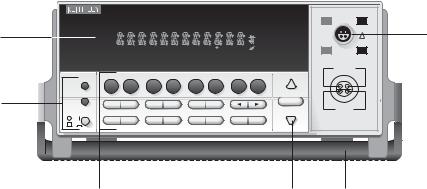
Getting Started |
1-7 |
|
|
Front and rear panel familiarization
Front panel summary
The front panel of the Model 2182 is shown in Figure 1-1. This figure includes important abbreviated information that should be reviewed before operating the instrument.
Figure 1-1
Model 2182 front panel
|
|
|
|
|
|
|
|
|
|
|
|
|
CHANNEL 1 |
|
|
|
|
|
|
|
|
|
|
|
|
|
HI |
LO |
|
4 |
REM |
STEP SCAN |
CH1 |
CH2 |
CH3 |
CH4 |
CH5 |
CH6 |
CH7 |
CH8 CH9 |
CH10 MATH |
|
|
5 |
TALK |
|
|
|
|
|
|
|
|
|
REAR |
|
! |
||
LSTN |
|
|
|
|
|
|
|
|
|
|
|
|||
SRQ |
|
|
|
|
|
|
|
|
|
|
|
|
||
SHIFT |
|
|
|
|
|
|
|
|
|
4W |
|
|
|
|
|
TIMER |
HOLD TRIG |
FAST |
MED |
SLOW |
REL |
FILT |
AUTO |
ERR |
BUFFER |
STAT |
HI |
LO |
|
|
|
|
|
|
|
|
|
|
|
|
|
|
CHANNEL 2
|
|
|
|
|
|
|
|
2182 NANOVOLTMETER |
120V MAX |
|||
|
|
|
|
|
|
|
|
|
|
|
||
|
|
MX+B |
% |
V1-V2 |
LSYNC |
TYPE |
OUTPUT |
AOUT |
TCOUPL |
|
|
|
|
SHIFT |
DCV1 |
DCV2 |
V1/V2 |
ACAL |
FILT |
REL |
TEMP |
TEMP |
|
|
|
|
|
|
|
|
|
|
|
1 |
2 |
RANGE |
|
|
1 |
LOCAL |
DELAY |
HOLD |
BUFFER |
LIMITS |
|
|
AUTO |
|
|||
EX TRIG |
TRIG |
STORE RECALL |
VALUE ON/OFF |
|
|
|
||||||
|
|
|
|
12V MAX |
||||||||
POWER |
CONFIG |
HALT |
SETUP |
GPIB |
RS232 |
CAL |
TEST |
RANGE |
||||
|
CAT I |
|||||||||||
|
|
|
|
|
|
|
|
EXIT |
ENTER |
|
||
|
|
STEP |
SCAN |
SAVE |
RESTR |
DIGITS |
RATE |
|
350V PEAK ANY |
|||
|
|
|
|
|
|
|
|
|
|
|
TERMINAL TO CHASSIS |
|
|
|
2 |
|
|
|
|
|
|
|
3 |
6 |
|
NOTE Most keys provide a dual function or operation. The nomenclature on a key indicates its unshifted function/operation, which is selected by pressing the key. Nomenclature (in blue) above a key indicates its shifted function. A shifted function is selected by pressing the SHIFT key and then the function/operation key.
1 Special keys and power switch
SHIFT |
Use to select a shifted function or operation. |
LOCAL |
Cancels GPIB remote mode. |
POWER |
Power switch. In position turns 2182 on (1), out position turns it off (0). |

1-8 Getting Started
2 Function and operation keys
Top Row |
|
Un-shifted |
|
DCV1 |
Selects Channel 1 voltage measurement function. |
DCV2 |
Selects Channel 2 voltage measurement function. |
V1/V2 |
Selects Ratio (Channel 1 voltage reading / Channel 2 voltage reading). |
ACAL |
Selects automatic gain calibration. |
FILT |
Enables/disables filter for selected measurement function. |
REL |
Enables/disables relative for selected measurement function. |
TEMP1 |
Selects Channel 1 temperature measurement function. |
TEMP2 |
Selects Channel 2 temperature measurement function. |
Shifted |
|
MX+B |
Multiplies a scale factor (M) to the reading (X) and then adds an offset (B). |
% |
Calculates percent deviation from a specified reference. |
V1-V2 |
Selects Delta; (V1t1 – V1t2)/2. |
LSYNC |
Enables/disables line cycle synchronization. When enabled, noise induced |
|
by the power line is reduced at the expense of speed. |
TYPE |
Select filter (analog and/or digital) and configure digital filter (window, |
|
count and type). |
OUTPUT |
Enables/disables relative for Analog Output. |
AOUT |
Enables/disables Analog Output. |
TCOUPL |
Configure temperature measurement (units, junction type, thermocouple |
|
type, sensor type). |
Middle Row |
|
Un-shifted |
|
EX-TRIG |
Selects external triggering (front panel, bus or trigger link) as trigger |
|
source. |
TRIG |
Triggers a measurement from the front panel. |
STORE |
Sets reading count for buffer and enables buffer. |
RECALL |
Displays stored readings (including maximum, minimum, peak-to-peak, |
|
average, and standard deviation). The and range keys scroll through |
|
the buffer, and the and key toggles between reading number and |
|
reading. |
VALUE |
Set the upper and lower limits for limit testing. |
ON/OFF |
Enables/disables limit testing, and selects beeper mode for limit testing. |
and |
Controls cursor position for making selections or editing values. |
Shifted |
|
DELAY |
Sets user delay between trigger and measurement. |
HOLD |
Holds reading when the specified number of samples is within the selected |
|
tolerance. |
 Loading...