


487


WARRANTY
Keithley Instruments, Inc. warrants this product to be free from defects in material and workmanship for a period of 1 year
from date of shipment.
Keithley Instruments, Inc. warrants the following items for 90 days from the date of shipment: probes, cables, rechargeable
batteries, diskettes, and documentation.
During the warranty period, we will, at our option, either repair or replace any product that prows to be defective,
To exercise this wammty, write or call your local Keithley representative, or contact Keithley headquarters in Cleveland, Ohio.
You will be given prompt assistance and return instructions. Send the product, transportation prepaid, to the indicated service
facility. Repairs will be made and the product returned, transportation prepaid. Repaired or replaced products are warranted for
the balance of the original warranty period, OT at least 90 days.
LIMITATION OF WARRANTY
This warranty does not apply to defects resulting from product modification without Keithley’s express written consent, or
misuse of any product or part. This warranty also does not apply to fuses, software, non-rechargeable batteries, damage from
battery leakage, 01 problems arising from normal we.a~ or failure to follow instructions.
THIS WARRANTY IS IN LIEU OF ALL OTHER WARRANTIES, EXPRESSED OR IMPLIED, INCLUDING ANY
IMPLIED WARRANTY OF MERCHANTABILITY OR FITNESS FOR A PARTICULAR USE. THE REMEDIES PRO-
VIDED HEREIN ARE BUYER’S SOLE AND EXCLUSIVE REMEDIES.
NEITHER KBITHLEY INSTRUMENTS, INC. NOR ANY OF ITS EMPLOYEES SHALL BE LIABLE FOR ANY DIRECT,
INDIRECT, SPECIAL, INCIDENTAL OR CONSEQUENTIAL DAMAGES ARISING OUT OF THE USE OF ITS
INSTRUMENTS AND SOFTWARE EVEN IF KEITHLEY INSTRUMENTS, INC., HAS BEEN ADVISED IN ADVANCE
OF THE POSSIBILITY OF SUCH DAMAGES. SUCH EXCLUDED DAMAGES SHALL INCLUDE, BUT ARE NOT LIM-
ITED TO: COSTS OF REMOVAL AND INSTALLATION, LOSSES SUSTAINED AS THE RESULT OF INJURY TO ANY
PERSON, OR DAMAGE TO PROPERTY.
Keithley Instruments, Inc. - 28775 Aurora R

Model 486 Picoammeter
Model 487 Picoammeter/Vokage Source
Instruction Manual
01990, Keithley Instruments, Inc.
All rights reserved.
Cleveland, Ohio, U.S.A.
Fourth Printing, August 2000
Document Number: 486-901-01 Rev. D
Manual Print History
The print history shown below lists the printing dates of all Revisions and Addenda created for this manual. The
Revision Level letter increases alphabetically as the manual undergoes subsequent updates. Addenda, which are
released between Revisions, contain important change information that the user should incorporate immediately into
the manual. Addenda are numbered sequentially. When a new Revision is created, all Addenda associated with the
previous Revision of the manual arc incorporated into the new Revision of the manual. Each new Revision includes
a revised copy of this print history page.
Revision C (Document Number 486-901-01)
............................................. December
1991
Revision D (Document Number 486-901-01).
................................................. August 2000

BESCHEJNIGUNG DES HERSTELLERS/IMl’ORTEURS
Hiermitwirdbescheinigt,(daS)/dasMODEL 486 PICOAMMETER AND MODEL 487 PICOAMMETER/
VOLTAGE SOURCEinUbereinstimmungmitdenBestimmungenderVfg1046/1984funksntstortist.DerDeuk~en
Bundespost
wurde
das Inverkehrbringen dieses Gerates angezeigt und die Berechtigmg ZUI Uberprufmg der Serie auf
Eiihmg der Bestimmungen eingeraumt.
Die Einhaltung der betreffenden Bestimmungen setzt vordus, dag, (da& geschirmte Mt$leitungen venvendet werden.
Fur die Beschaffung richtiger Me~leitungen ist der Betreiber verantwortlich.
DIESES GERAET WURDE SOWOHL ElNZELN ALS AUCH IN ElNERANLAGE, DIE EINEN NORMALW
ANWENDUNGSFALL NACHBILDET, AUF DIE EINHALTUNG DER FEN
GEPRUEFT. EST IS JEDOCH MOEGLICH, DASS DIE
FUNK-ENTSTOEXB -GEN IJNTFX
UNGUENSTIGEN UMSTAENDEN BEI ANDEREN
G
ERAETEKOMBJNATIONEN NIGHT EINGEHALTEN
WERDEN. FUER DIE EINHALTIJNG DER FUNK-ENTSTOERBE GEN SEINER GESAMTEN ANLAGE,
IN DER DlESES GERAET BETRIEBEN WlRD, IST DER B?ZlXEZBER VERANTWORTLICH.
Keithley Instruments, Incorporated
CERTIFICATE BY MANUFACTURER/TMPORTER
ThisistocertlfythattheheMODEL
SOURCE isshielded againstadiointerferenceinaccordancewiththeprovisions ofVfglO46/1984. TheGermanPostal
Services have been advised that this device is being put on the market and that they have been given the right to inspect
the series for compliance with the regulations.
Compliance with applicable regulations depends on the use of shielded cables. It is the user who is responsible for pry-
curing the appropriate cables.
THIS EQUlFMENT HAS BEEN TFSTED CONCERNING COMPLIANCE WITH THE RELFVANT RFl PROTEC-
TION REQUIREMENTS BOTH lNDMDUALLY AND ON SYSTEM LEVEL (TO
SIMULATE NORMAL OPERA-
TION CONDlTIONS). HOWEVER, IT IS POSSIBLE THAT THESE RFI RBQ-
ARENOTMETUNJXR
CERTAIN UNFAV0RABL.E CONDlTIONS IN OTHER INSTALLATIONS. lT IS THE USER WHO IS RESPONSI-
BLE FOR COMX’LIAN
CE OF HIS PARTICULAR INSTALLATION.
Keithley Instruments, Incorporated


Safety Precautions
The following safety precautions should be observed before using
this product and soy associated instrumentation. Although some in-
mument~ and accessories would normally be used with non-haz-
ardous voltages, there are situations where hazardous conditions
may he present.
This product is intended for use by qualified personnel who recog-
nize shock hazards and am familiar with the safety precautions m-
quired to avoid possible injury. Read the operating information
carefully before using the product.
The types of product users are
Responsible body is the individual or group responsible for the use
and maintenance of equipment, for ensuring that the equipment is
operated within its specifications and operating limits, and for en-
suring that operators are adequately trained.
Operators use the product for its intended function. They most be
trained in electrical safety procedures and proper use of the instm-
ment. They most be protected from electric shock and contact with
hazardous live circuits.
Maintenance personnel perform routine procedures on the product
to keep it operating, for example, setting the line voltage or replac-
ing consumable materials. Maintenance procedures are described in
the manual. The procedures explicitly state if the operator may per-
form them. Otherwise, they should be performed only by service
persomlel.
Service personnel are trained to work on live circuits, and perform
safe installations and repairs of products. Only properly trained ser-
vice personnel may perform installation and service procedures.
Exercise extreme caution when a shock hazard is present. Lethal
voltage may he present an cable connector jacks or test fixtures. The
American National Standards Institote (ANSI) states that a shock
hazard exists when voltage levels greater than 3OV RMS, 42.4V
peak, or 60VDC are present. A good safety practice is to expect
that hazardous voltage is present in any unknown circuit before
measuring.
Users of this product most be protected from electric shock at all
times. The responsible body must ensure that users are prevented
access and/or insulated from every connection point. Io some cases,
connections must be exposed to potential human contact. Product
users in these circumstances most be trained to protect themselves
from the risk of electric shock. If the circuit is capable of operating
at or above 1000 volts, no conductive part of the circuit may be
exposed.
As described in the International Electrotcchnical Commission
(IEC) Standard IEC 664, digital multimeter measuring circuits
(e.g., Keitbley Models I75A. 199, 2000,2001,2W2, and 2010) are
Installation Category II. All other instruments signal terminals are
Installation Category I and most not be connected to mains.
Do not connect switching cards directly to unlimited power circuits.
They are intended to be used with impedance limited sources.
NEVER connect switching cards directly to AC mains. When con-
necting sources to switching cards, install protective devices to lim-
it fault cwrent and voltage to the card.
Before operating an instrument, make sore the line cord is connect-
cd to a properly grounded power receptacle. Inspect the connecting
cables, test leads, and jumpers for possible wear, cracks, or breaks
before each we.
For maximom safety, do not touch the product, test cables, or any
other instruments while power is applied to tic circuit under test.
ALWAYS remove power from the entire test system and discharge
any capacitors before: connecting or disconnecting cables or jomp-
en, installing or removing switching cards, or making internal
changes, such as installing or removing jumpers.
Do not touch any object that could provide a cormot path to the
common side of the circuit under test or power line (earth) ground.
Always make measurements with dry hands while standing on a
dry, insulated surface capable of withstanding the voltage being
measured.
The instrument and accessories must be used in accordance with its
specifications and operating instructions or the safety of the equip-
ment may be impaired.
Do not exceed the maximum signal levels of the instruments and ac-
cessories, as defined in the specifications and operating infonna-
don, and es shown on the instrument or test fixture panels, or
switching card.
When fuses are used in a product, replace with same type and rating
for continued protection against tire hazard.
Chassis connections must only be used as shield connections for
measuring circuits, NOT as safety earth ground connections.
If you are using a test fixture, keep the lid closed while power is ap-
plied to the device under test. Safe operation requires the use of a
lid interlock.
Ifa@ screw is present, connect it to safety earth ground using the
wire recommended in the user documentation.
Then
symbol on an instmment indicates that the user should E-
fer to the operating instructions located in the manual.
-Ibe A
symbol on an instrument shows that it can source or mea-
sure 1000 volts or more, including the combined effect of normal
and common mode voltages. Use standard safety precautions to
avoid personal contact with these voltages.
The WARNING heading in a manual explains dangers that might
result in personal injury or death. Always read the associated infor-
mation very carefully before performing the indicated procedure.
The CAUTION heading in a manual explains hazards that could
damage the instrument. Such damage may invalidate the warranty.
Instrumentation and accessories shall not be connected to humans.
Before performing any maintenance, disconnect the line cord and
all test cables.
To maintain protection from electric shock end tire, replacement
components in mains circuits, including the power transformer, test
leads, and input jacks, must be purchased from Keithley Instn-
menu. Standard fuses, with applicable national safety approvals,
may be used if the rating and type are the same. Other components
that are not safety related may be purchased from other suppliers as
long as they are equivalent to the original component. (Note that se-
lected parts should be purchased only through Keithley Insrmments
to maintain accuracy and functionality of the product.) If you are
unsure about the applicability of a replacement component, call a
Keithley Instruments office for information.
To clean an instrument, use a damp cloth or mild, water based
cleaner. Clean the exterior of the instmment only. Do not apply
cleaner directly to the instrument or allow liquids to enter or spill
on the instrument. Products that consist of a circuit board with no
case or chassis (e.g., data acquisition board for installation into a
computer) should never require cleaning if handled according to in-
structions. If the board becomes contaminated and operation is af-
fected, the board should he returned to the factmy for proper
cleaning/servicing.
Rev. IO/99

SAFETY WARNINGS
The following prec.~tions should be observed before us-
ing Model 4&X/487. Refer to main manual for detailed
safety information and complete operating instructions.
The Model 486/487 is intended for use by qualified per-
sonnel who recognize shock hazards snd are familiar
with the safety precautions required to avoid possible in-
jury. Read over the instruction manual carefully before
using the ins+nunent.
Before operating the instrument, make sore the line cord
is connected to a properly grounded power receptacle.
Exercise extreme caution when a shock hazard is present.
Lethal voltages may be present on the test fixture or the
Model 487 output jacks. The American National Stan-
dards Institute WNSI) states that a shock hazard exists
when voltage levels greater than 30V RMS or 424V peak
are present. A good safety practice is to expect that haz-
ardo~voltageispresentinany~o~cirmitbefore
measuriug.
Inspect the connecting cables, test leads, and jumpers for
possible wear, cracks, or breaks before each use.
Formadmumsafety,donot touchtheModel487connec-
tions, teat fixture, test cables or connections to any other
instruments while power is applied to the circuit under
test. Turn off all power and discharge all capacitors be-
fore connecting or disconnecdng cables or jumpas. Also,
keep the test fixture lid dosed while power is applied to
the device under test. Safe operation requires the use of
the lid interlock.
Do not touch any object which could provide a current
path to the common side of the &cuit under test or
power line (earth) ground.
Do not exceed the maximum signal levels of the in&u-
ment, as shown on the rear panel and as defined in the
specifications and operation section of the instnxtion
manual.
Connect the - screw of the test fixture to safety earth
0
ground using #I8 AWG or larger wire.
hstmnentation and accessories should not be connected
to humans.
Maintenance should only be performed by qualified
service personnel. Before performing any maintenance,
disconnect the line cord and all test cables from the in-
strument.
CONTROL SUMMARY
DISPLAY INTENSl7Y: Selects normal/dim/off display.
LOCAL: Places unit in local and restores front panel key
opergion.
MENU: Use with the knob or cursor keys to configure the
following menu items; data store, data recall, I-limit
(Model487), integration, IEEE-488 bus Coos or talk-only),
defaults, self&t, debug, calibrate, and V-Source calibrate
(Model 487 only).
SHIFT EXIT:
&ik MENLJ or trigger SETUP.
ZERO CHECK Allows check of offsets, and must be dis-
abled to obtain an input signal measurement.
SHIFT CORRECT: Performs automatic zero correction to
null insment offsets.
FILTER: Enables or disables the selected filter(s).
SHIFTFILTER SELECT: Use with knob or cursor to select
the f&r(s); digital, analog, or digital + analog.
REL Use to establish a baseline using the displayedread-
ing.
V RANGE A: Use range keys to select a lower or higher
current range.
SHm AUTO RANGE: Use to enable/disable autorange.
SETLIP: Use with knob or cursor keys to con@ure the fol-
lowingtriggersetupitems;triggermode,triggerinterval,
trigger delay, and bigger source.
OPERATE: Places V-Source of Model 487 in operate or
standby.
TRIGGEE Press to trigger a reading or start the data
store.
PRESET: Toggles between two preset V-Source values
(Model 487 only).
SHIFT OHMS cV/Ij: Press to select V/I Ohms.
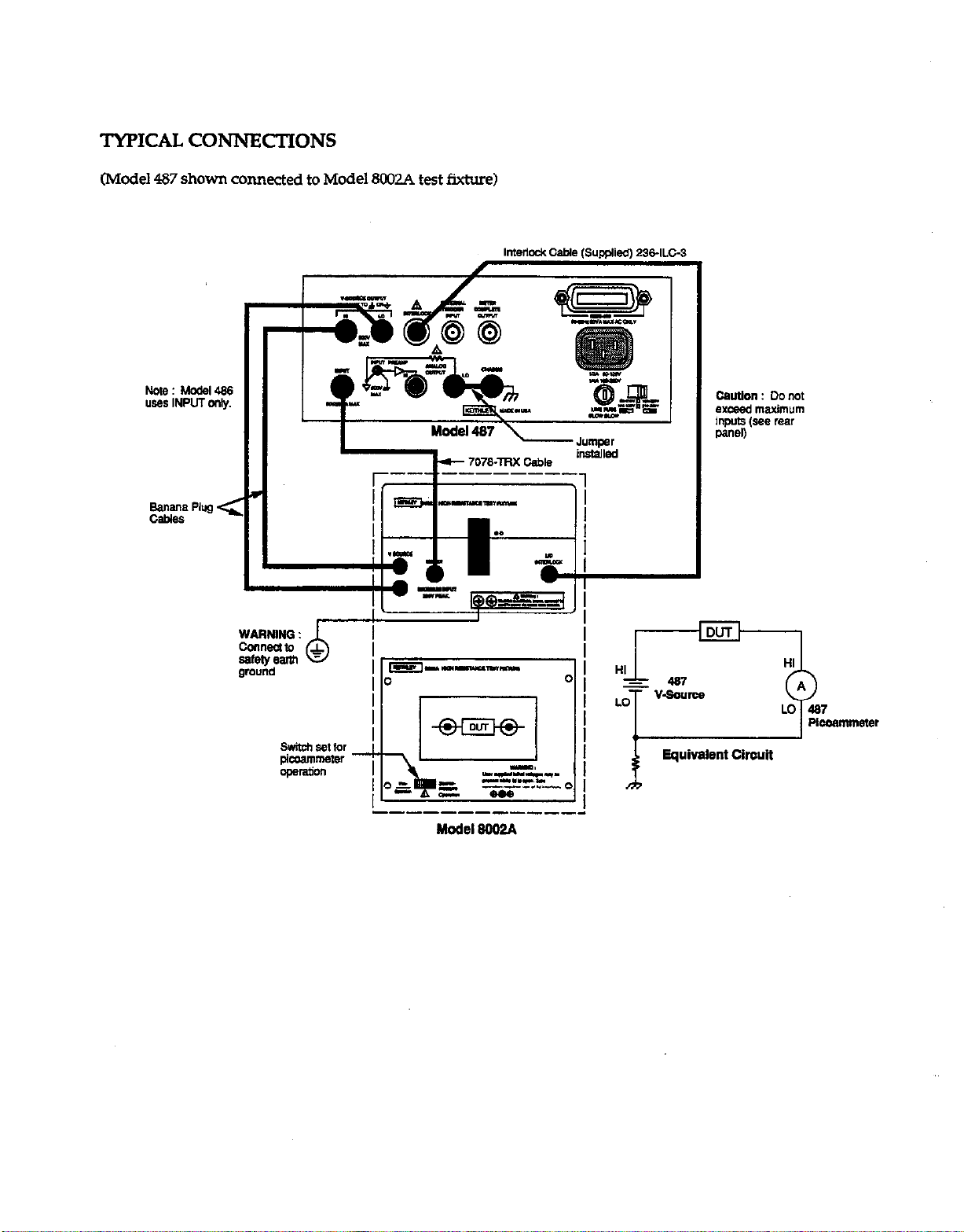
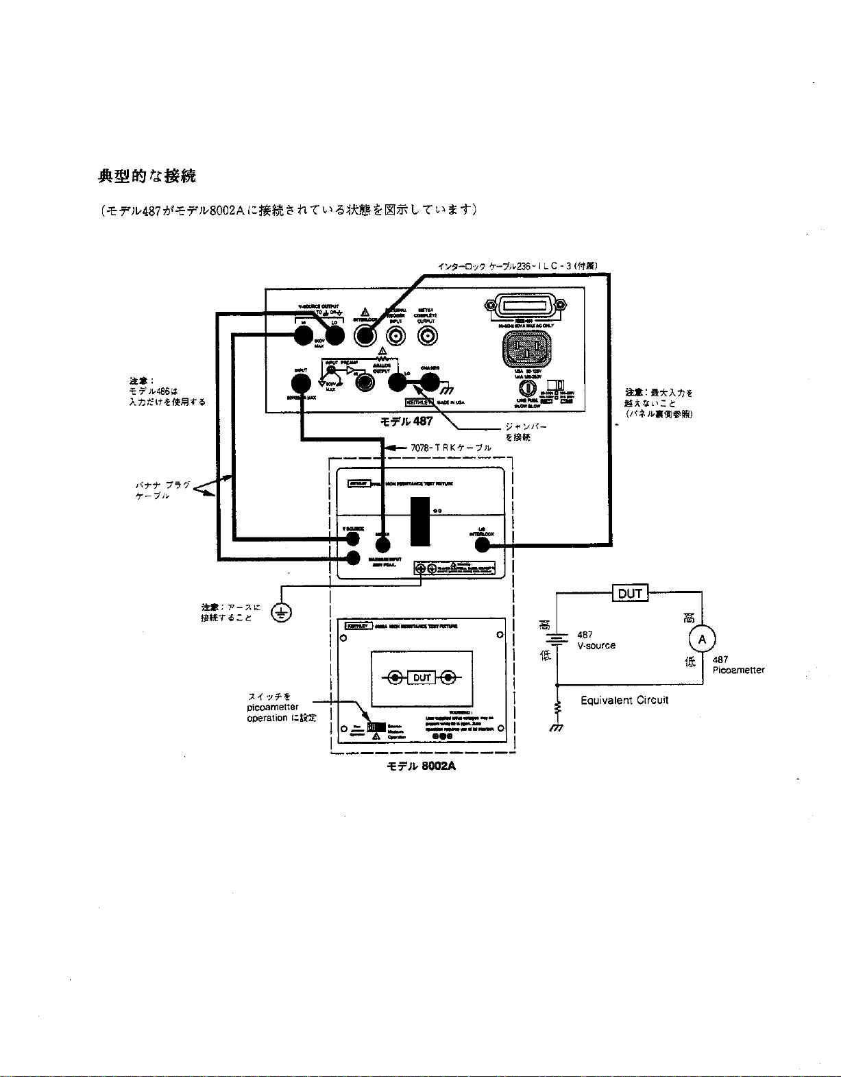
TYPICAL CONNECTIONS
(Model 487 shown connected to Model 8CKQA test fixture)
TL
HI
- 487
LO
T
“-so”rcw
0
A
LO 487
Plcoammeter
i
Equivalent circuit
Model 8002A

CONSIGhTS DE SECURITF!
n faut prendre les pr&autions suivames avant d’wiliw les me
d&les 4861487. Veuilk vow reporter au manuel principal qui
comiem tous les remeignemenu sur les consigns de skcuritt
ainsi qw les clirectiva d’utilisation.
LE mod&s 4861487 soot destiks a des spkialistes cotxcients
des dangers de secow &cuique et co-t les mesur-es de
prkntion g prendre pour eviter tout risque de blesnuex. Veui-
lez lire attentivemeot ce manxl avant d’utiliser l’insmtment.
V&&z., avant d’utiliser I’instmment, que le cordon soit branchC
SW une prise convenablement reli& B la term.
Redoublez de pr&autions lorsqu’il existe tm risque de secow
&cttique. Des tenkn.5 moxtelks risqueot d’&.e pksentes au
n&au du circuit d’essais ou des j&s de sortie du mcckle 487.
selon l’instintt amticain des normes (ANSI), il e&e ml risque
de secousse &cuique lorsque le nivem de la tension d+asse 30 V
efficaces ou 42,4 VC de tension c&e. If esf toujours prudent
de consid&r.er qu’une tension dangerewe est prknte dam
tout circuit incomm avant dkffectua une mesure.
Examinez l’itat da cslbles de cotmexion, des fils d’& et des
cavaliers pour s’asurer qu’ils ne prksentent ni &g&B d’usure, ni
aaqlxlures, ni fissures want chaqlle essai.
Pour un maximum de s&m-it& ne touchez pas les fik du mod&
487,
le circuit de mesure, les &les d’essais, ni les braochemenn
a attam mm inmument lotxque le circuit en mm-s d’essai est
at.5 tension. Coupe2 l’alimentation en comam et d&barge2 tous
les con~teun avant de braocher ou de &brancber d-es c5ble-s.
ll faut +akment veiller A ce que le couvercle du circuit de mesure
d’mais mte fermi pendant que l’appareil en cow-s d’essai est
sous tension. Le vermuillage du couvercle et nkssaire pour tm
foIutiomlemem en tome skmi~.
Ne touchez aucun objet susceptible de fomnir tm chemin con-
ductem vers le c&k commun du tit en cows d’essai ou la ter-
re (masse) &I circuit d’alimeotxion.
Ne .L+SS.Z pa 1s nivemx
maximum de sigoaux de l’iosav
malt 6gurant sur le pamleau an&e et d&is a” chapitre carat-
t&istiques et folxxionnement de la notice d’utilisatiotl.
Fiiezlavis Q dudrruitd’eyaisalaterregl’aided’un~de
jauge 18 AWG ou plus gms.
lnsrmmena et accgsoiTes
ne dokent pas be oxcord& g des per-
somles
lo ne faut faire edcuter la maintenance que par du penonnel Spe
cialisd. Dkbranchez le cordon d’alimentation et tous les Cgbler
d’esais de I’instmment avant d’effecmer tme quelconque o@ra
don de maintenance.
RESUME DES COMMANDES
lNZBX!SIl?E D’AFHCHAGE (DISPLAY lNTEN.SITyI :
Pennet de s&ctiomw : normaL&.ible!pas d’affichage.
COMMANDE DIRECZZ (LOCAL) :
Permet de commander di-
r-em l’appareil et remet en foxtionnement les touches du
panneau d’affichage.
MENU (MENU) : s’udise avec le bouton on les touches du NT-
sew pour configurer Ia &mems suivants du menu : mise en
m&mire de dam&, rappel de doonkes, limite I (tooMe 487),
int&mion, le bus EEE-488 (voie de tmmmksion ou communi-
cation seulement), v&m par d4fam, contrble automatique, mise
au point, balormage et &lomage de la source de tension V
(mod&
487 seulement).
TOUCHE MAJUSCUJX - SORllE (SHIFTEXI’IJ :
Permet
de soti du MENU oli de d&lencher I’INSTALLATION
@ETup).
lrwFCATIoN DU ZERO (ZERO CHECK) :
Pet-met la v&i-
ficatim cles d4cdam et doit &re invalid& pour obtenir le signal
normal de sortie.
TOUCHI? MAJUSCULE - CORRECTION (SHlFT COR-
RECTJ : R&l&e la mix e z&o automatique pour am-&r les
c2kcalaga des instruments.
TOUCHF MAJUSCULE - SELECTION DU FLXRE
(SHIFT FILTER SELECT) : s’urilise avec le bouton ou le cur-
seu pour selectiotmer le(s) filtfe(s); mm&iqtx, analogique 0”
numkique + analogique.
V RANGE A (RANGE) :
Utilkez les touches de gamme pcnu
selectiomler lme gamme plus basse ou plus haute.
TOUCHE MAJ(ISCULE - GAMME AUTOMAnQUE
(SHIFi- AUTO RANGE) : s’wilis pour valider ou irmlickr
k
mode gamme automatique.
IhSTALLATION (SETUP) : s’unlise avec un bouton ou les
touches c,mems pour configurer le ciichchmat des systemes
de cklenchemem suivaoa : mode &clenchement, intervalle de
Wenchement, retard de dklencbemem et source de dkclencbe
*em.
FONCli’ONNEMtWT (OPERA=) : Met la source
de tension
V du ma&k 487 en fonaioonement ou en veik.
DECLWCI.zW@h’T (TRIGGER) :
Appuyez pour d-klmcber
tme lecture ou d&arer la mix en memoire des doom&.
PREREGLAGE (PRESEV :
Pa-met de ba.scuk entre V&LIE de
sources de t&on V (mod& 487 seulement).
TOUCHE MAJUSCULE - OHMS (SHI3T OHMS V@ :
Ap
puyez pour sactiomler v/l ohms.
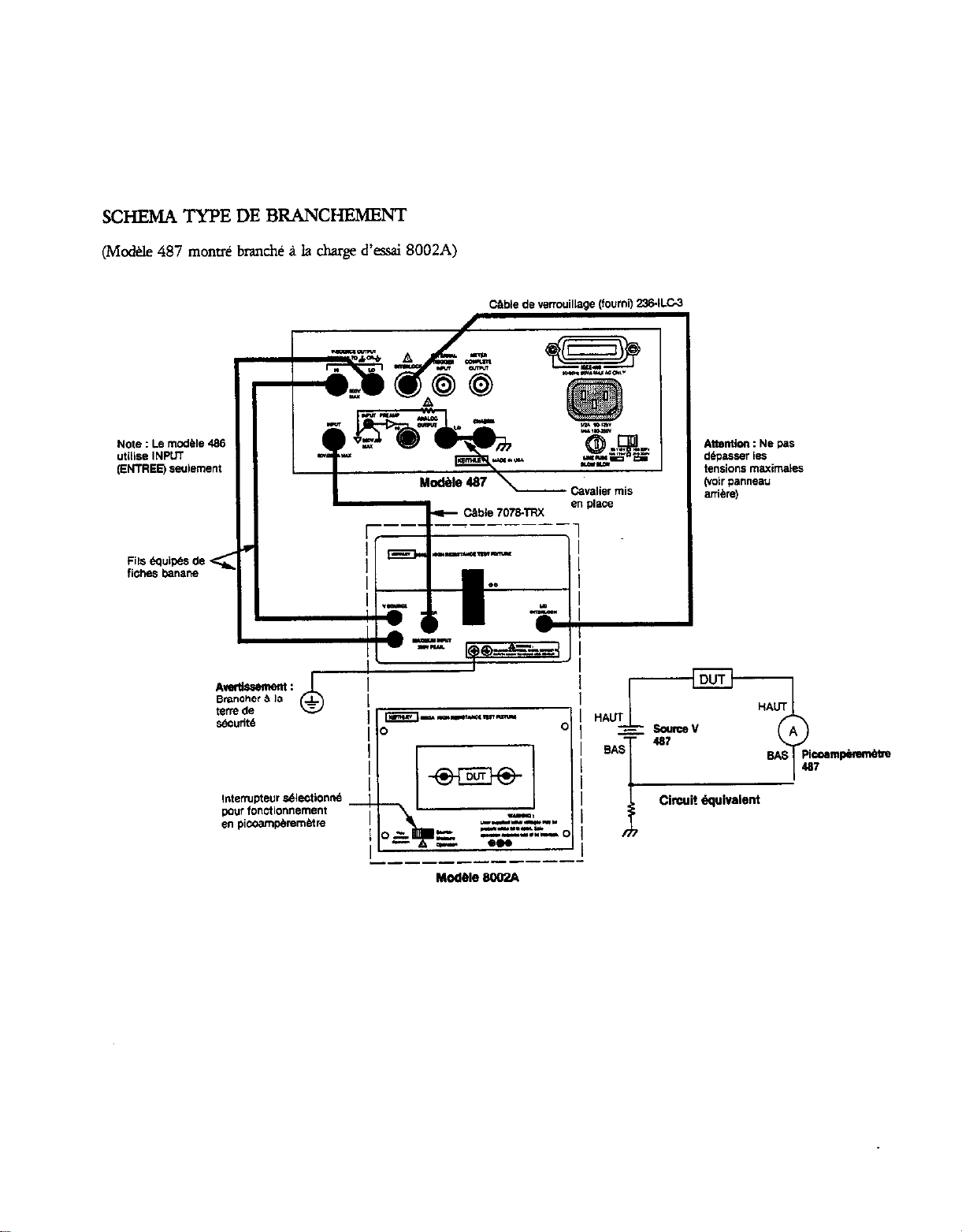
SCHEMA TYPE DE BRANCHFNENT
(Mcd+.le 487 mom& branch& P Ia charge d’csai 8002A)
DUT
k
Cimit dquivalent

SICHERHEITSHINWEISE
Vor dem Gebrauch des M&ells 4861487 soIlten Sie folgende
Vorkehrungen &fen. Wenden Sie sich hinsichtlich ausfiihr-
lither Sicherheitsinformationen und vollst&~diger Bedienungsm
weisungen an das Haupthandbucb.
Dar M&U 4861487 is fiir den Gebrauch durch qu&izierts
Personal ausgelegt, das eine Stromwhkggefahr erkenm und mit
da Sicherheitworkehmngehrungen vertraut ist, die zur Verhinderung
einer mbglicben Verletzung pea&n we&n miisxn Vor den
G&much des G&&s sollten Sie da Anweisungshandbuch sorg-
fag lesen.
Vor Uxtriebnabme des G&es soilten Sic da-auf achten, da&
da Suomkabel mit einer vo~ig gee&ten Suomquelk
verbunden is.
S&e Suomvhlaggefabr best&n, so g&en Sie mit Xuiulsenter
Vosicbt var. Auf der Tatvonichtung c&r den Amcbliisxn des
Modells 487 kijnnen t&&he Sparmungen vorhanden sein. Das
American National Standard Institute (ANSQ weist damuf bin,
da& eine Suomschlagg~ dam besteht, wenn die SFannungs-
wene h6her als 30 Volt RMS oder 42,4 Volt Spia&is@.mg be
uagen. Eine gute Sicherhei@nahme ist die Vermu-
tnng, da& in jedem unbekannten Stromkreis vor dem MS
sen eine g&liche Spamung vorhanden is.
PrJfen Sie vor jeder
BmuQung
alle Verbindungskabel, Priif?abel
md
Briicken auf m&$icbe Abnutnmg, Rise cder Briiche.
Beriibren Sie LUT maxim&n Siiherheit keine Amcbiiisse, Priif-
vonichtungen, Priifkabel ode Verbindungen zu anderen Ge
men, w&rend der zu priifende S~omkreis mit Strom versorgt
wird. Sellen Sic den Strom ab und entladen Sic alle Konden-
satmen, bevor Sic K&l c&r Briicken an&Ii&n oder trennen.
H&en Sic auBer&m den Testmscbl&deckel ggchlos~en, with-
rend das zu priifende G&t mit Strom versorgr wird. Eine sichere
Bedhung bedeutet die Benutzung e&s Deckeischlosses.
Baiihrm Sie keinen Gegastan& der eine Stmmleitung LUT ge
meinsamen site des zll priifendsI stmmkreises cder deI Strom-
katebnaw dare&.
iiberschreiten Sic nicht die auf da Riickseite des G&&es verge
gebenen HlichstwMe, die auBer&m ix-n Kapitel Tech&&e
Dawn und Beuieb da Bediemmgshandbuchs bschrieba sind.
V&inda Sie die
0
= Scbraube des Pr&xchl- mit Hilfe
eims Nr. 18 AWG c&r gr&ren Kabels mit da Masse.
Geme und Zubehtir s&a nicbt an Mahen an&+scblassen
werden.
Die Wammg s&e nut durch qualifiziertes Penxnl vorgenom-
men werden. Vor einer Wammg des Get-&s solken das Strom-
k&l und alle anderen Priifkabel van diem geuennt werden.
KONTROLLBEGRIFF’E
AN.ZIGEHELLIGKEIT (DISPLAY Ihfl.ENSI~):
Wtit
Anzeige normaUabgedunkeltiaus.
LOKAL (LOCAL):
Bringt Geriit in Local-Modus und stellt
Frontabdeckungstastenfunkdon wieder her.
Genii (MENlJ: Venvenden Sie diesen B&hl nsammen x-nit
den Knopf- c&r C~rtasten, um f&en& Meniidaten abzu-
r&n: $&hem der Dawn (data store), Abmfen der Data (data
red), IGrenrwert (Rimit) (Mcddl 487), Integlatioxl (mte-
gradon), IEEE-488 VielfKhlenmg (nur Vielfachleitung a.&
Gqdch), Nullstellungen (~dts), Sehtpriifung (seXtest), Em-
stijren (debug), Eicben (calibrate) und Spannungs4u~~tichu,-,g
(V-Sowc~ calibrate) (nw MC&II 487).
SHIFT EXIT (SHIFT EXIZJ: Bender, ME& c&r auslijsen
SETUP.
NULL?‘RiiFUNG (ZERO Ch!ECK):
Em@licbt Priifung der
Abweicbungen und mui3 zum Erhaltm einer F.ingabesig-
nabnaung unterbrwhen we&a.
SHFi- CORRECT (SHLFT CORRECT Fiibrt automatische
Nullkorrektur ZUT Nulhllmg der Ger&abwichungen durcb.
FZLTER (RZERJ: Bet&&t oder unterbricht da?&& gewiihlte(n)
Filter.
SHIFi-FLLTER WAHL (.SHL=TRLll?R SELECn: Venvenden
SiediesenBefeblr
usammen nit Kxpf c&r Cunor, urn die Fil-
ter zu bestimmm; digital, analog cder digital und analog.
REL (R.&C): Verwada Sie diezen Befehl, urn linen Gnmthvert
fiir die angezeigte Ablesung faulegen.
V BJZREICH A (RAh’GE):
Benutzen Sie diese Bereichsmsen,
urn e&n nkdrigeren oder h&eren Strombereicb festzulegen.
SHIFT AUTO-BEREICH (SHIFT AUTO RANGE):
Verwen-
den Sie diesen B&l, um den AutoBaeicb (autorange) Befehl
zu aktividd.
AUIT7ELLVNG (SEW): Verwenden Sie diesen Befehl zu-
sammen mit den Knopf- odet Curscnasten zur Kon&uration fol-
gender TrQeritnp~ufsteUun~; Trig&mndus, Trigger-
intervaIl, Tti~emerr6genmg und TriggerqueUe.
BETRlEE(OPERATE):
Bringt Spannungsquelle de Mcdells
487 in Be&b c&r Standbymcdu.
TRIGGER (ZWGGER): Betitip Sic dige Taste, urn eine Ab
lesung cder die speichaung “on Lktm awdiisen.
VORGABE (PREFl-: Schdtet zwischm zwti vor~e&enen
Spannm~uellenwerten (mu Modell487).
SHIFT OHM (V/I) (SHIFT OHMS V7Ij:
Driicken Sie dies=
Taste, urn V/I Ohm zu betimmen.
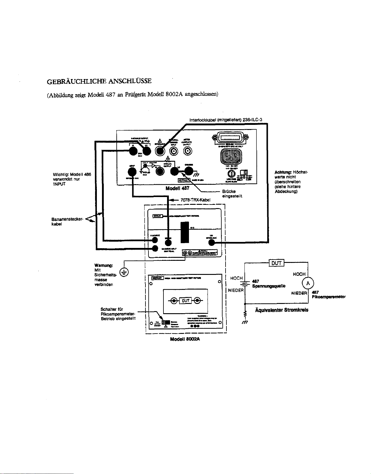
GEBRiiUCHLICHE ANSCHLijSSE
(Abbildq zeigt McdeU 487 an Priifgeriit Mcdell8002A “I@chlossen)
I
T
I
NORME DI SICUREZZA
Le name di sicurezza segwnd dew10 mere mervate prima di
ware U modello 4861487. Fate riftiento al rnmuaie principale
per “ngsioti demgu suue norme di sicurn e le is”lKio”i per
I’uro.
II modello 4861487 e’ stat0 progetrato ad uo di pe~nale
qlmlificato, a co”cscenza CM Ii&i0 di sccma elemica ed awnte
-ma’ co” le preca”z.ioti necemarie per evimre ogni da”“0
possibiie a persane e case. Leggem attentamente quest0 “ranwale
prima di udliuare lo sml”lento.
Prima di far fu”zionare lo sml”lento, &%sic”ratevi the il cordone
elemico sia appmmamente adlegato ad una press di alimenta-
zione CO” la mesa a terra ccuretm.
Prrstate esn-ema atten7io”e in situazioni in cui e’ prwnte il
rischio di sccaa elletrica sulk3 -ento 0 “el cimdto di prow%
in qtmnto e’ p&bile the vi si rilevino tensioni considerate letah
imprerse dall’utente. L‘ANSI (American National Standard In-
sti~te)riconmceurischiodismssaelemicdinpresenraditen-
sioni di picco ma&xi di 30V RSM o 42.4V. E’ buona “orma
coti* presenti tensio”i peric&se i” ogni circllito elemico
slxmxiuto.
Controllate i cavi di mnnesSone ed i conmti prima delYw per
witare problemi cwati da usurq crepe o romue.
Per maggior sicurezza, “on toccate il cirtito ed i cavi di prova, 0
II” qualsiasi ah smlme”t0 una volm applicam -te al cir-
ait0 di prow. Diskwrite I’alimentazione e saricam tutti i con-
densatori prima di connette~e o sonmetwe i cati. Mante”ete in-
oh chi”so il cope&h dell’impianto di prow quando si applica
corrente au’apparecchio the ti vuole prowre. Per ““‘@Gne
sicwa necesrio un copxhio the, se apert”, bloxhi
aut0”laticame”te 1 parsaggio di ccrrelte dl’apparecchio.
Non tcccate alcun oggetto the possa ccmvmtire passaggio di COP
reme al km conlune dd circuit0 in prwa 0 aIla massa (tara) ala
linea d.i tensione.
Non superate l’ingreso di tensione nwsimo, come yxcifiato
nell’appmito capitol0 sul hnzio”a”wnto, conten”to in quest0
nmnuale.
collegatelavite 1 d.eu’apparecchiaturadiproMa-usan-
0
do~un avo No.18 AWG o pii~ spgso.
Gli -enti e gli accessori non devono mai - collegati ad
esxriumani.
IA “m”uterKio”e dew gsere equita esclusivame”te da per-
so”& q”alificato. Prima di efkmMre ahn lavoro di “m”“teD
ione scollegate u Lea”0 di hea e tuni gu alti cavi di prcwa daIl0
SO-lU”~rO.
IUASSUh’TO DJ3 COMANDI
INDICA TORE INZWSITA ’ (DISPLAY INllENSIITyI:
Peimette la selezione delh chiareua delhdicatore tra “or-
“mldchiarol~to.
LOCALE (LOCAL]:
Pane il dis@tivo in wo locale e riprki”a
l’opemivim’ del pannell a ati.
MENU (MJZNV): Wene usam aamite la mancpla 0
i tarti del
cursore per scegliere “a: menlorizzazicole dati, richianlo dati,
limite di corrente (Modello 487), integrazim, conngsione
IEEE-488 (connesione 0 solo speaker), dehllt, test autonmtico,
debug, calibratua. e calibrantra sorgente di tasione. (Solo
modello 487).
.sHlmExlT (Srnrn~: Exe ti menu e prowxa la IM-
zlALrzzAz10NE.
CONTROLLO RLPRIS7liVO (ZERO CHECK): Commte il
mnuoUo degli offset, e deve esere dkinwito per omenere un
seg”ale nornmle in lmcim.
CORREZIONE SHIFT (SHIFT CORRECT):
Effenua
autGmaticar”ente una cotrezio”e di ripristi”0 per a”““llare la
telciione di &et dell0 smlme”to.
FEZ?0 (FUTER): Aziona 0 diskeke i flui sekio”ati.
sHIFT~oNEmmo (.s%TFILl-ERsElEc1): uwe
la rnmopola 0 U amore per scegliere il f&c(i): di&ale,
analo~co, oppure digimle + analogico.
REL @EL): Usato per stabike un punt0 di rihirnento uando i
dati “xsuati.
V CAMP0 DI VARlAZIONL? A, (FLANGE): Usate
i tasti del
campdivariadoneperseler&uncampodi-per
la corrente piti “as0 0 phi risueno.
SHl?i- CAMP0 DI VARIAZIONE AUTOMAlTCO (SIfIFT
AUTO RANGE): Usato per aricmareldidnsaire il camp di
variazione autmnatico.
-ONE (SE’TW): Usate k nmnopch o i msti del
l2umn-e per la ccm6gurazione delle s.eguellti carattetistiche dd in?
pulw (nigger); mcdulo trig&a, il-lmrvaJlo, rimrda, e sorgente.
FUNZONAhfENTO (OPERATE):
Rmde operadva o mate in
mea la sorgente di taskme deI MakIlo 487.
IMPLLLSO (EQIGGER): Premete imp&o per ottenere ““a let-
ma 0 dare inizio alla mfznmimione dati.
PREsELEnONE (PRESEZJ: sama Isa k due pxizioni COT-
l-i!pnde”ti ai due vd0I-i predetaminati per la sorge”te di tar
&me. (Solo M&k 487).
SHIFT OHM (v/l) (Srn OHMS v7: Premete per scegliere
lami.uenzai”ohmsvn.
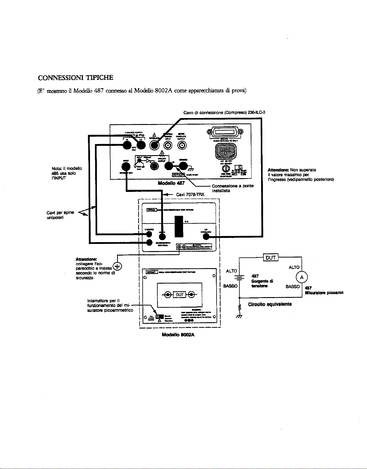
c0NNEss10NI TIPICHE
(E’ n-,nstrato il Mod& 487 connesso al Mod& 8002A come aw&tura di prova)
i
11-w-w
-I”....L
.__---_-----
Mdek.8W2A
___ _-------
1
M-m-
.o
i3iL
.-
-"=-I
zz"
Z3ZZ!kZ
_----B-e-----
E=JL 8oOP.A
ADVERTENCIAS DE SEGURIDAD
Las precaucione siguientes deben ser observadas arms de war
los Modelm 4861487. Remitirse al manual principal para infor-
ma&n detdada de xgtuidad e instmccion~ completas de fun-
donamiento.
Tener cuidado extreme cuando hay la posibilidad de chque elk-
trim. F’wdem existi voltajes letaks en ks davijas de tida del
Mod& 487 6 en el accesorio de prueba. El Ins&to National
Ameicmo de Norms (ANSI) expose que e&e un peligro de
chcque cuando bay presents niveks de vohaje de mk de 30V
VCM (valor cuadrhtico media) 0 de 42,4V pica. Una buaa
pktica de seguridad es la de espemr que haya voltajes
peligmscs presentcs en cdquier circuito desconocido
antes de medirlo.
No war nin@n objeto que pudka provea un camino a la cc-
tieme al Iado comirn &I circuim bajo prueba o la tiena de la
line3 de energia.
SUMARIO DE CONTROL
LNTENSIDAD DE PRESENTACION (DLWAY INllW
SIm): selffdonar
preentack% normal/amotigzuh/apa~da.
LOCAL (LOCAL):
Pane a la unidad en acci6n local y restaura la
OperadLin de la llave de] panel delantero.
MENU (MEh’U): Se usa con lar Uaves del cursor o perilla para
mdigum lo siguiente: alma- ‘elm de dates, recuperaci6Il
de dam, limite de coniam 0 (Mcdelo 487), integradn, bam
IEEE-488 (balm 0 tile voz), surdtuci6n, autqlmeh, ebmina-
cibn de fallas, cezdilmtibn y calibraci6n de fuente de voltaje (V)
(sdo
Mod&
487).
CAMBIO SALWA (SHFi-m: S&b del MENU o activa-
citi de Prepara&n (SETUP).
COMPROBACION DE CERO (ZERO CHECK):
Permite la
compmbacih de desplammientos y dek ser inhabilitado par-a ob
tenermamedici6nde~deenuada.
CORFECION DE DEV’LAZAMZW TO (SHIFT COR-
RECT R& correcd6n autcm&ica de cero para balancear de
plazaodentos del instnunento.
Fm-Ro (EllTER): Habilita 0 inbabilita el 0 los iiltm s.2k.io
rlados.
~GAMAA~GE):UsalasUaverdegamapara~~onar
lmgamade conimte mis elm 0 mAs baja.
CAMBIO GAMA AUTOMATICA (SHIFT AUTO
RANGE)): Se wa pm bab la gama autodtica.
PREPARACION (SE77lP): Usado cm Uaves de tumor o periua
pal-a Nmiigurar la disposiciones sigulenm d-2 activti6n: moda-
lidad de activtibn, imervalo de activaci6n, demaa de activaci6n.
fuente de acdvacih.
OPERACION (OPERAlF): Siti k
Fueme V del Modelo 487
en Funcionamiu~ta o Espwa.
AC’i7XACION (TRIGGER): Se deprime para activar una kc-
turd 0 catlauar al almacenamulto de dam.
PREAJUSZE(P~: OS& emre cim v&n-es de la
Fueme V
preajustados (s5lo Mod& 487).
CAMBIOS OHMIOS v/c (SHIJT OHMS v7q se
optime para
sek@ilmal otios Voltaje coniente.
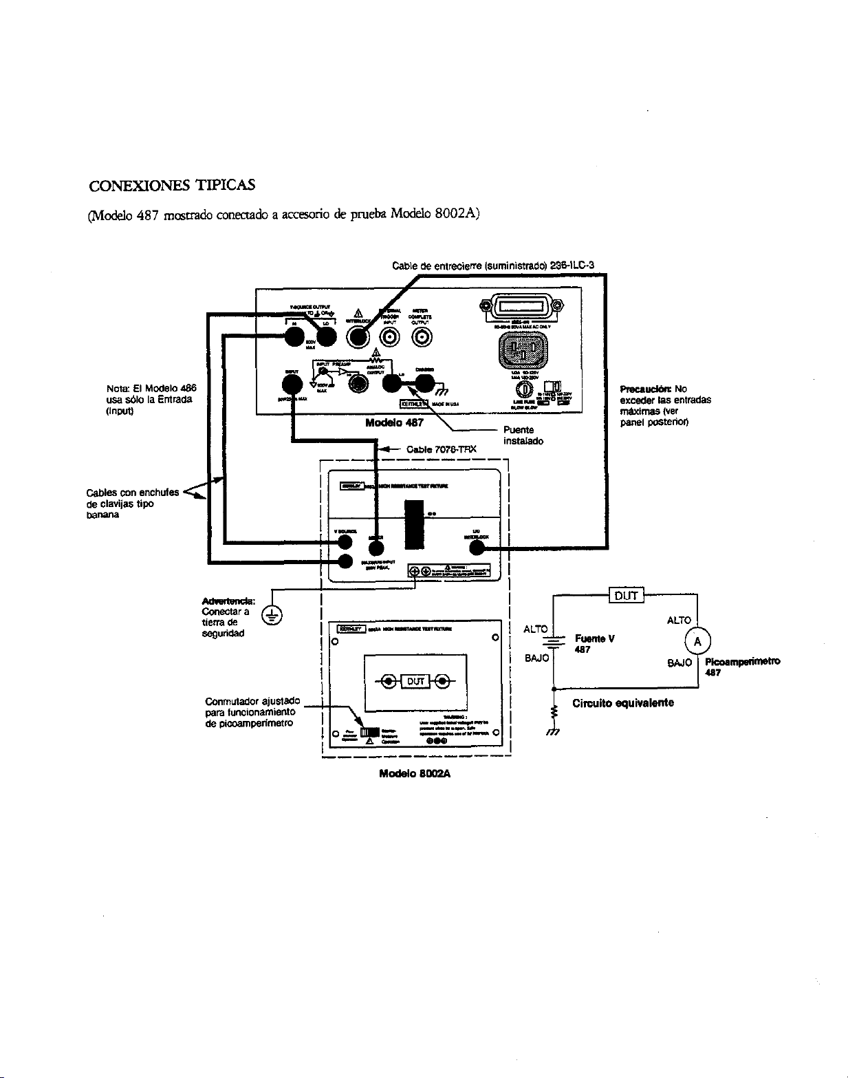
CONEXIONES TIPICAS
(Mod.90 487 mcsuado conmado a arreylrio de pm& M&lo 8002A)
- .--------.
w-P--
i
Circuit0 equivatente
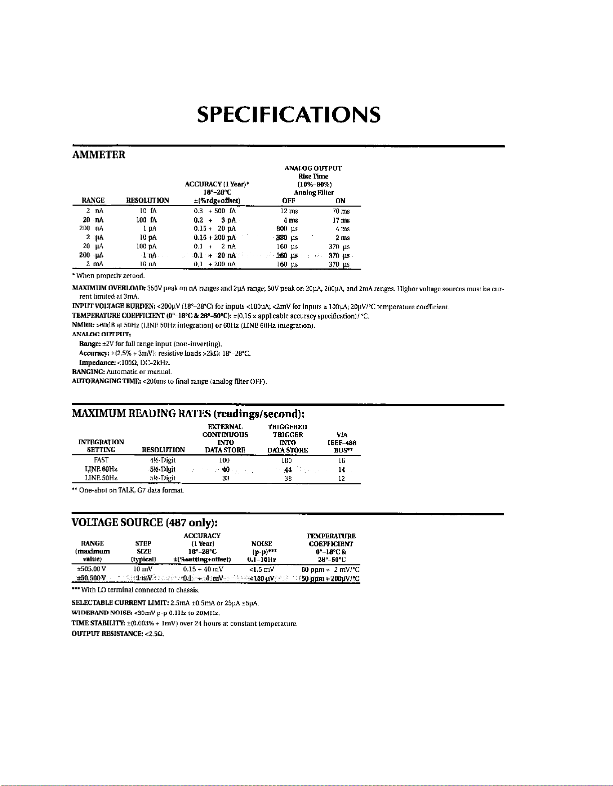
SPECIFICATIONS
MAXIMUM READING RATES (readings/second):
VOLTAGE SOURCE (487 only):
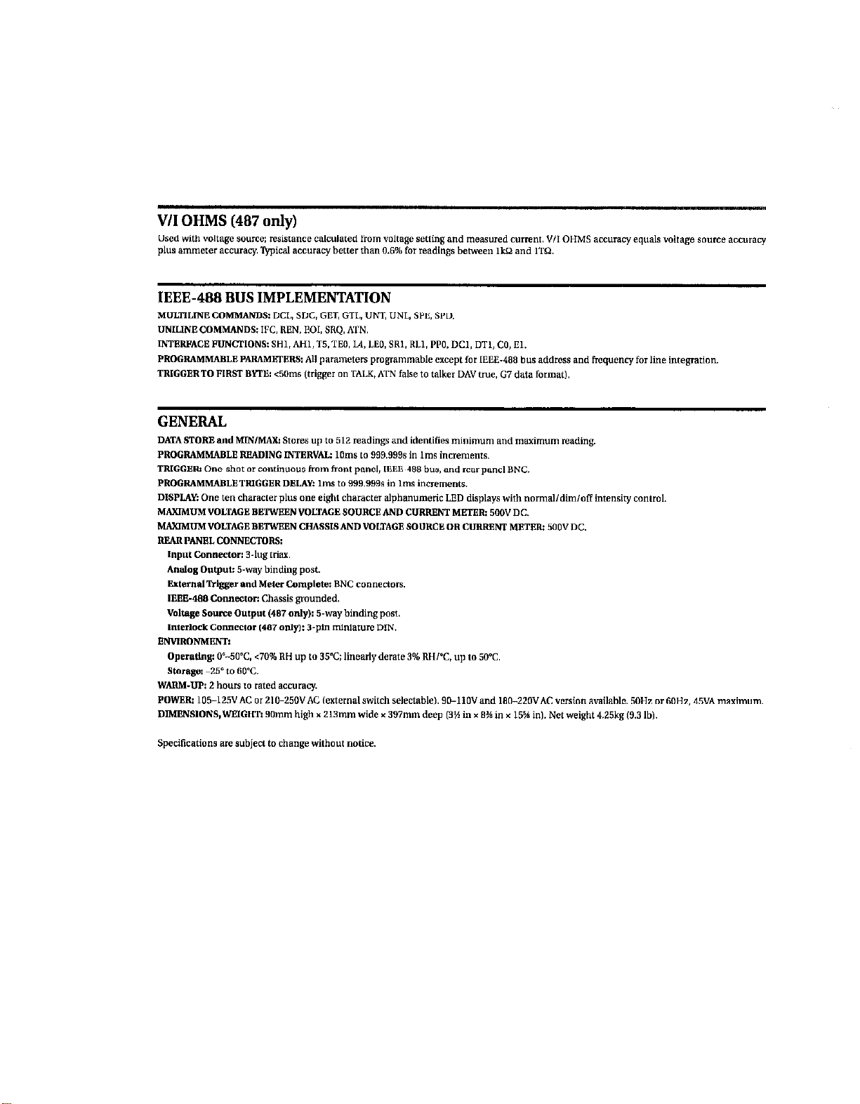
IEEE-488 BUS IMPLEMENTATION
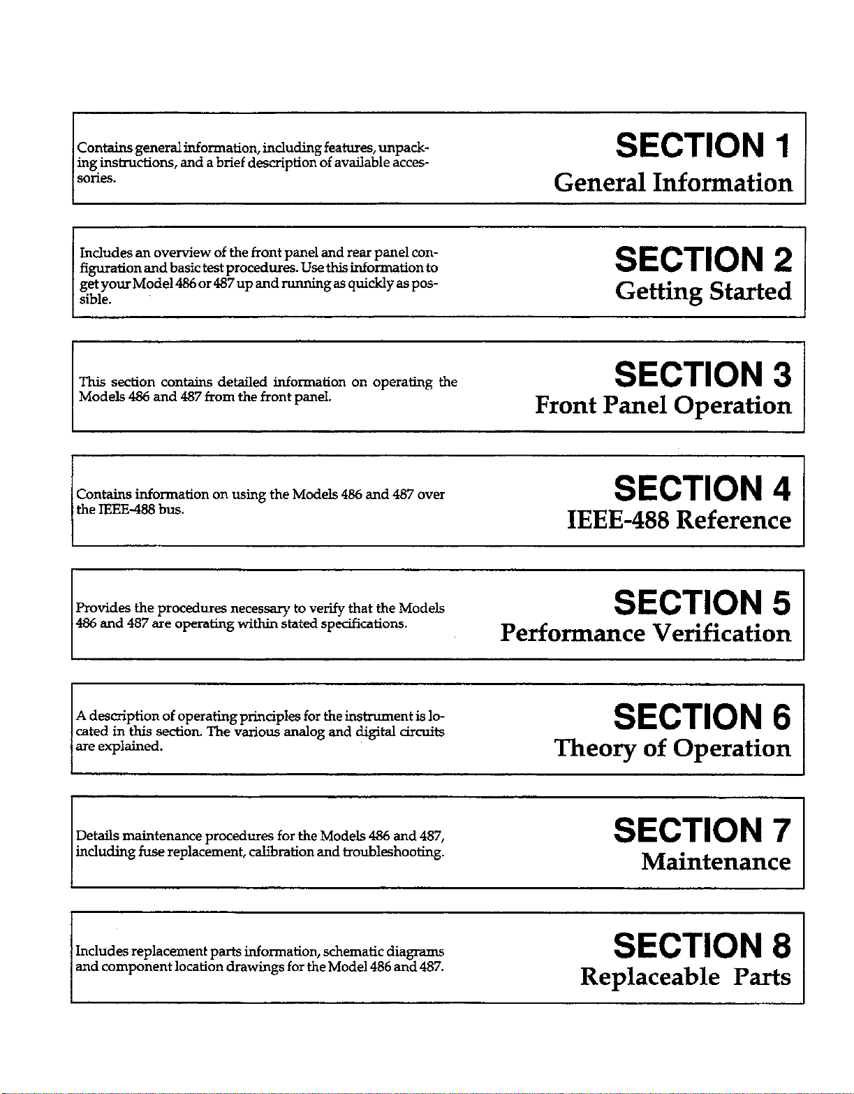
contains general information, inclding features, unpack-
ing insimxtions, and a brief description of available acces-
SO&S.
SECTION
1
General Information
Includes an overview of the front panel and rear panel con-
figuration and basic test procedures. Use this information to
getyourMode1486or487up andmmingas quicklyaspos-
sible.
SECTION 2
Getting Started
This section contains detailed information on operating the
SECTION 3
Front Panel Operation
Models 486 and 487 from the front panel.
Contains information on using the Models 466 and 487 over
the IEEE-488 bus.
SECTION 4
IEEE-488 Reference
Provides the procedures necessary to verify that the Models
486 and 487 are operating within stated specifications.
SECTION 5
Performance Verification
I 1
I
I
A description of operating principles for the instrument is lo-
cated in this section. The various analog and digital circuits
are explained.
SECTION 6
Theory of Operation
Details maintenance procedures for the Models 486 and 487,
including fuse replacement, calibration and troubleshooting.
SECTION 7
Maintenance
Includes replacement parts information, schematic diagrams
and component location drawings for the Model 486 and 487.
SECTION 8
Replaceable Parts

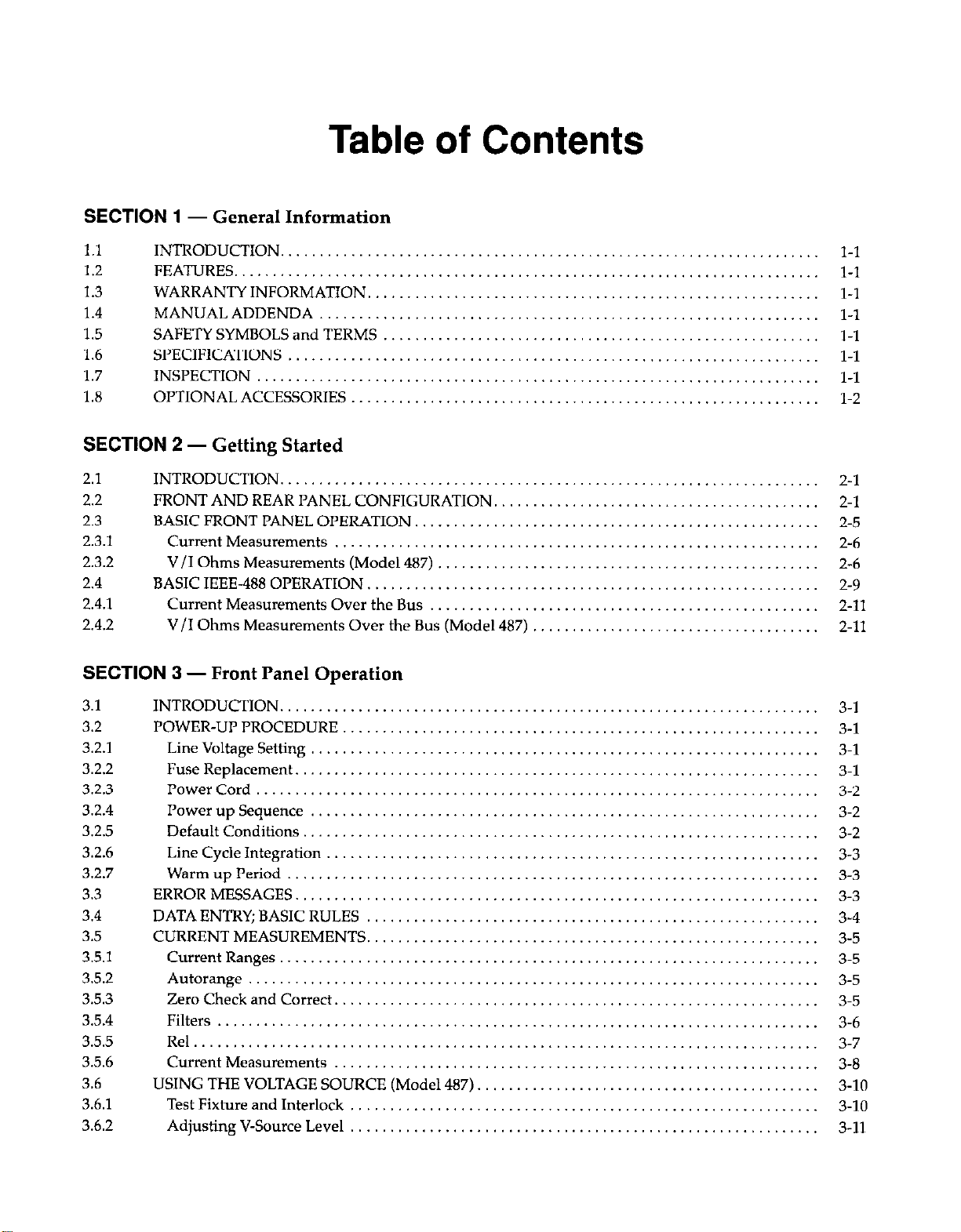
Table of Contents
SECTION 1
- General Information
1.1
INTRODUCTION.
1.2 FEATURES.
1.3 WARRANTY INFORMATION,
1.4
MANUAL ADDENDA
1.5
SAFETY SYMBOLS and TERMS
1.6
SPECIFICATIONS
1.7
INSPECTION
1.8
OPTIONAL ACCESSORIES
SECTION 2
- Getting Started
2.1
2.2
2.3
2.3.1
2.3.2
2.4
2.4.1
2.4.2
INTRODUCTION
...................................
FRONT AND REAR PANEL CONFIGURATION,
.......
BASIC FRONT PANEL OPERATION.
.................
Current Measurements
............................
V/I Ohms Measurements (Model 487)
...............
BASIC IEEE-488 OPERATION. .......................
Current Measurements Over the Bus
................
V/I Ohms Measurements Over the Bus (Model 487)
...
SECTION
3 - Front Panel Operation
3.1
3.2
3.2.1
3.2.2
3.2.3
3.2.4
3.2.5
3.2.6
3.2.7
3.3
3.4
3.5
3.5.1
3.5.2
3.5.3
3.5.4
3.5.5
3.5.6
3.6
3.6.1
3.6.2
INTRODUCTION.
POWER-UP PROCEDURE
Line Voltage Setting
Fuse Replacement
Power Cord
Power up Sequence
Default Conditions
Line Cycle Integration
Warm up Period
ERROR MESSAGES
DATA ENTRY; BASIC RULES
CURRENT MEASUREMENTS.
Current Ranges.
Autorange
Zero Check and Correct.
Filters
Rel......................................
Current Measurements
USING THE VOLTAGE SOURCE (Model 487)
Test Fixture and Interlock
Adjusting V-Source Level
.................
.................
.................
.................
.................
.................
.................
.................
.........
.........
.........
.........
.........
.........
.........
.........
..............
2-l
..............
2-l
..............
2-5
..............
2-6
..............
2-6
..............
2-9
..............
2-11
..............
2-11
3-l
3-1
3-l
3-l
3-2
3-2
3-2
3-3
3-3
3-3
3-4
3-5
3-5
3-5
3-5
3-6
3-7
3-8
3-10
3-10
3-11
3.6.3
3.6.4
3.6.5
3.6.6
3.7
3.8
3.8.1
3.82
3.8.3
3.8.4
3.8.5
3.8.6
3.8.7
3.8.8
3.8.9
3.8.10
3.9
3.9.1
3.9.2
3.9.3
3.9.4
3.9.5
3.10
3.10.1
3.102
3.11
3.11.1
3.112
3.11.3
3.12
3.13
3.14
3.14.1
3.14.2
3.15
3.15.1
3.15.2
3.16
3.16.1
3.16.2
3.16.3
3.16.4
3.16.5
3.16.6
3.16.7
3.16.8
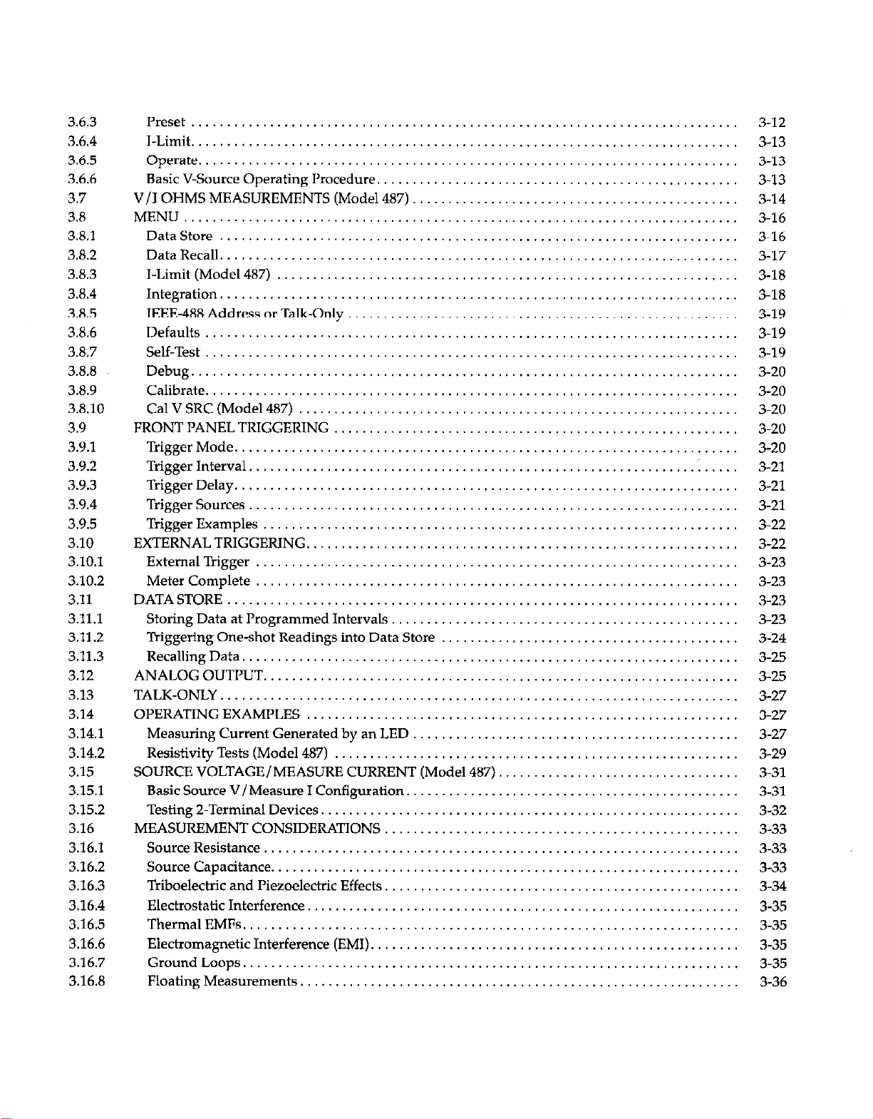
Preset .............................................................................
I-Limit .............................................................................
Operate ............................................................................
Basic V-Source Operating Procedure.
..................................................
V/I OHMS MEASUREMENTS (Model 487)
..............................................
MENU ..............................................................................
DataStore .........................................................................
DataRecall .........................................................................
I-Limit(Model487) .................................................................
Integration .........................................................................
IEEE-488AddressorTalk.Only .......................................................
Defau~s ...........................................................................
Self-Test ...........................................................................
Debug .............................................................................
Calibrate ...........................................................................
CalVSRC(Mode1487) ..............................................................
FRONTPANELTRIGGERING .........................................................
TriggerMode .......................................................................
TriggerInterval...............................................................~
.....
TriggerDelay .......................................................................
Trigger Sources
.....................................................................
Trigger Examples ...................................................................
EXTERNAL TRIGGERING.
............................................................
ExternalTrigger ....................................................................
Meter Complete ....................................................................
DATASTORE ........................................................................
Storing Data at Programmed Intervals, ................................................
Triggering One-shot Readings into Data Store
..........................................
RecallingData ......................................................................
ANALOGOUTPUT ...................................................................
TALK-ONLY .........................................................................
OPERATINGEXAMPLES .............................................................
Measuring Current Generated by an LED ..............................................
Resistivity Tests (Model 487) .........................................................
SOURCE VOLTAGE/MEASURE CURRENT (Model 487). .................................
Basic Source V/Measure I Configuration.
..............................................
Testing2-TerminalDevices ...........................................................
MEASUREMENT CONSIDERATIONS ..................................................
Source Resistance. ..................................................................
SourceCapacitance ..................................................................
Triboelectric and I’iezoelectric Effects. .................................................
Electrostatic Interference. ............................................................
ThermalEMFs ......................................................................
Electromagnetic Interference (EMI). ...................................................
GroundLoops ......................................................................
Floating Measurements
..............................................................
3-12
3-13
3-13
3-13
3-14
3-16
3-16
3-17
3-18
3-18
3-19
3-19
3-19
3-20
3-20
3-20
3-20
3-20
3-21
3-21
3-21
3-22
3-22
3-23
3-23
3-23
3-23
3-24
3-25
3-25
3-27
3-27
3-27
3-29
3-31
3-31
3-32
3-33
3-33
3-33
3-34
3-35
3-35
3-35
3-35
3-36
SECTION 4
- IEEE-488 Reference
4.1
4.2
4.2.1
4.2.2
4.2.3
4.2.4
4.2.5
4.2.6
4.2.7
4.2.8
4.2.9
4.2.10
4.2.11
4.2.12
4.2.13
4.2.14
4.2.15
4.2.16
4.2.17
4.2.18
4.2.19
4.2.20
4.2.21
4.2.22
4.2.23
4.2.24
4.3
4.3.1
4.3.2
4.3.3
4.3.4
4.3.5
4.3.6
4.3.7
4.3.8
4.4
4.5
4.6
4.7
4.7.1
4.7.2
4.7.3
4.8
INTRODUCTION
.....................................................................
DEVICE-DEPENDENT COMMAND PROGRAMMING
...................................
A-Display Intensity
...............................................................
B-ReadingSource
.................................................................
C . Zero Check and Zero Correct. ....................................................
D-Display.
......................................................................
F-V/IOhms
......................................................................
G-DataFormat
...................................................................
H-HitControl
....................................................................
J-Self-Tests. ......................................................................
K . EOI and Bus Hold-Off. ..........................................................
..
L-Default Condlhons or Calibration. ................................................
M - SRQ Mask and Serial Poll Byte Format
............................................
N-DDataStore;ArmandSetSize..
...................................................
0-Operate(Mode1487)
............................................................
P-Filters
.........................................................................
Q-Interval
.......................................................................
R-Range .........................................................................
S~IntegrationPeriod
...............................................................
T-Trigger
........................................................................
u-status .........................................................................
V-VoltageSource
.................................................................
W~Delay .........................................................................
X-Execute
........................................................................
Y-Terminator
.....................................................................
Z-Relative
.......................................................................
GENERAL BUS COMMANDS. .........................................................
REN(RemoteEnable)
................................................................
IFC (InterfaceClear) .................................................................
LLO(LocalLockout)
.................................................................
GTL (Go To Local) and Local .........................................................
DCL(DeviceClear)
..................................................................
SDC(SelectiveDeviceClear)
.........................................................
GET (Group Execute Trigger)
.........................................................
SPE, SPD (Serial Polling)
.............................................................
IEEE-488BUSCONNECTIONS
.........................................................
PRIMARY ADDRESS SELECTION
......................................................
CONTROLLER PROGRAMMING
......................................................
FRONT PANEL ASPECTS OF IEEE-488 OPERATION .....................................
Front PanelError Messages
...........................................................
IEEE-488 Status Indicators. ...........................................................
LOCALKey
........................................................................
BUS DATA TRANSMISSION TIMES ....................................................
4-l
4-1
4-6
4-7
4-8
4-9
4.10
4-11
4-15
4-16
4-17
4.19
4-21
4-24
4.26
4-27
4-28
4-29
4-30
4.31
4-32
4-38
4-39
4-40
4-41
4-42
4-44
4-44
4-44
4-45
4-45
4-45
4-45
4-45
4-46
4-46
4-47
4-48
4-48
4-48
4-50
4-51
4-51
SECTION
5 - Performance Verification
5.1 INTRODUCTION
....................................................................
5.2 ENVIRONMENTALCONDITIONS
.....................................................
5.3 INITIALCONDITIONS
...............................................................
5.4 REQUIREDTESTEQUIPMENT
........................................................
5.5 VERIFICATION PROCEDURES ........................................................
5.5.1 PicoammeterVeri~cation..
..........................................................
5.5.2 Voltage Source Verification (Model 487). ...............................................
SECTION 6
- Theory of Operation
6.1
INTRODUCTION
6.2 ANALOG CIRCUITS.
6.2.1 Input Amplifier.
6.2.2 Analog Filter
6.2.3 Multiplexer . ..__. .., ., ,., ._, ,_
6.2.4 +2.8V Reference
6.2.5 Analog Output
6.2.6 Voltage Source (Model 487).
6.3 ANALOG CONTROL CIRCUITRY.
6.4
A/D CONVERTER
6.5 DIGITAL CIRCUITS
6.5.1
Digital Block Diagram.
6.5.2
Microcomputer
6.5.3 Display/Keyboard.
6.5.4 IEEE-488 Interface .
6.6 POWER SUPPLIES
6.6.1 ACLineInput..........................
6.6.2
*15V Supplies
6.6.3
+5VA Supply. .
6.6.4
+6.5V Supply.
.
.
.
. .
SECTION
7 - Maintenance
7.1 INTRODUCTION . . . . . . . . . . . . . . . . . . . . . . . . . .._.
7.2 LINE FUSE REPLACEMENT.
7.3
CALIBRATION.
7.3.1
Recommended Calibration Equipment.
7.3.2
Environmental Conditions
7.3.3
CAL LOCK Switch.
7.3.4 Warm-Up Period.
7.3.5 Front Panel Calibration
7.3.6 IEEE-488 Bus Calibration . .
7.4 HANDLING AND CLEANING PRECAUTIONS
7.5 DISASSEMBLY................................
7.5.1 CoverRemoval..............................
7.5.2 Shield Removal.
5-l
5-l
5-1
5-l
5-2
5-2
s-4
6-l
6-1
6-1
6-2
6-3
6-3
6-5
6-5
6-6
6-8
6-9
6-9
6-11
6-12
6-13
6-14
6-14
6-14
6-14
6-14
7-1
7-l
7-1
7-1
7-2
7-2
7-2
7-2
7-6
7-8
7-9
7-9
7-11
7.5.3
Front Panel Removal
................................
7.5.4
Circuit Board Removal.
..............................
7.6
SPECIAL HANDLING OF STATIC SENSITIVE DEVICES
7.7
TROUBLESHOOTING
................................
7.7.1
Recommended Troubleshooting Equipment
............
7.7.2
Self-Test
...........................................
7.7.3
Analog Control Lines.
...............................
7.7.4
A/D Test Mode
.....................................
7.7.5
Troubleshooting Procedures
..........................
7.7.6
Input Offset Voltage Adjust.
..........................
7.7.7
Fusible Resistor Replacement,
........................
..........
..........
..........
..........
..........
..........
..........
..........
..........
..........
..........
SECTION
8 - Replaceable Parts
8.1
INTRODUCTION........................................................
8.2
PARTSLISTS............................................................
8.3
ORDERINGINFORMATION..............................................
5.4
FACTORYSERVICE......................................................
8.5
SCHEMATIC DIAGRAMS AND COMPONENT LOCATION DRAWINGS.
APPENDICES
A
Device-dependent Command Summary
B
Interface Function Codes.
C ASCII Character Codes and IEEE-488 Multiline Interface Command Messages.
D
Controllerrrograms.......................................................
E
IEEE-488BusOverview....................................................
7-11
7-11
7-11
7-12
7-12
7-12
7-12
7-13
7-13
7-19
7-19
8-l
8-l
8-l
8-l
8-l
A-l
B-l
C-l
D-l
E-l

 Loading...