


 Loading...
Keithley 3720, 3740, 3730, 3723, 3722 User Manual
...www.keithley.com
Series 3700 System Switch/Multimeter
User’s Manual
3700S-900-01 Rev. A / August 2007
A G R E A T E R M E A S U R E O F C O N F I D E N C E

WARRANTY
Keithley Instruments, Inc. warrants this product to be free from defects in material and workmanship for a period of one (1) year from date of shipment.
Keithley Instruments, Inc. warrants the following items for 90 days from the date of shipment: probes, cables, software, rechargeable batteries, diskettes, and documentation.
During the warranty period, Keithley Instruments will, at its option, either repair or replace any product that proves to be defective.
To exercise this warranty, write or call your local Keithley Instruments representative, or contact
Keithley Instruments headquarters in Cleveland, Ohio. You will be given prompt assistance and return instructions. Send the product, transportation prepaid, to the indicated service facility. Repairs will be made and the product returned, transportation prepaid. Repaired or replaced products are warranted for the balance of the original warranty period, or at least 90 days.
LIMITATION OF WARRANTY
This warranty does not apply to defects resulting from product modification without Keithley Instruments’ express written consent, or misuse of any product or part. This warranty also does not apply to fuses, software, non-rechargeable batteries, damage from battery leakage, or problems arising from normal wear or failure to follow instructions.
THIS WARRANTY IS IN LIEU OF ALL OTHER WARRANTIES, EXPRESSED OR IMPLIED, INCLUDING ANY IMPLIED WARRANTY OF MERCHANTABILITY OR FITNESS FOR A PARTICULAR USE. THE REMEDIES PROVIDED HEREIN ARE BUYER’S SOLE AND EXCLUSIVE REMEDIES.
NEITHER KEITHLEY INSTRUMENTS, INC. NOR ANY OF ITS EMPLOYEES SHALL BE LIABLE FOR ANY DIRECT, INDIRECT, SPECIAL, INCIDENTAL, OR CONSEQUENTIAL DAMAGES ARISING OUT OF THE USE OF ITS INSTRUMENTS AND SOFTWARE, EVEN IF KEITHLEY INSTRUMENTS, INC. HAS BEEN ADVISED IN ADVANCE OF THE POSSIBILITY OF SUCH DAMAGES. SUCH EXCLUDED DAMAGES SHALL INCLUDE, BUT ARE NOT LIMITED TO: COST OF REMOVAL AND INSTALLATION, LOSSES SUSTAINED AS THE RESULT OF INJURY TO ANY PERSON, OR DAMAGE TO PROPERTY.
AG R E A T E R M E A S U R E O F C O N F I D E N C E
Keithley Instruments, Inc.
CorporateHeadquarters• 28775 Aurora Road • Cleveland, Ohio 44139 440-248-0400 • Fax: 440-248-6168 • 1-888-KEITHLEY (1-888-534-8453) • www.keithley.com
3/07
Series 3700
System Switch/Multimeter
User's Manual
©2007, Keithley Instruments, Inc.
All rights reserved.
Cleveland, Ohio, U.S.A.
Document Number: 3700S-900-01 Rev. A / August 2007

Manual Print History
The print history shown below lists the printing dates of all Revisions and Addenda created for this manual. The Revision Level letter increases alphabetically as the manual undergoes subsequent updates. Addenda, which are released between Revisions, contain important change information that the user should incorporate immediately into the manual. Addenda are numbered sequentially. When a new Revision is created, all Addenda associated with the previous Revision of the manual are incorporated into the new Revision of the manual. Each new Revision includes a revised copy of this print history page.
Document Number: 3700S-900-01 Rev. A ........................................ |
August 2007 |
All Keithley Instruments product names are trademarks or registered trademarks of Keithley Instruments, Inc.
Other brand names are trademarks or registered trademarks of their respective holders.

Safety Precautions
The following safety precautions should be observed before using this product and any associated instrumentation. Although some instruments and accessories would normally be used with non-hazardous voltages, there are situations where hazardous conditions may be present.
This product is intended for use by qualified personnel who recognize shock hazards and are familiar with the safety precautions required to avoid possible injury. Read and follow all installation, operation, and maintenance information carefully before using the product. Refer to the user documentation for complete product specifications.
If the product is used in a manner not specified, the protection provided by the product warranty may be impaired.
The types of product users are:
Responsible body is the individual or group responsible for the use and maintenance of equipment, for ensuring that the equipment is operated within its specifications and operating limits, and for ensuring that operators are adequately trained.
Operators use the product for its intended function. They must be trained in electrical safety procedures and proper use of the instrument. They must be protected from electric shock and contact with hazardous live circuits.
Maintenance personnel perform routine procedures on the product to keep it operating properly, for example, setting the line voltage or replacing consumable materials. Maintenance procedures are described in the user documentation. The procedures explicitly state if the operator may perform them. Otherwise, they should be performed only by service personnel.
Service personnel are trained to work on live circuits, perform safe installations, and repair products. Only properly trained service personnel may perform installation and service procedures.
Keithley Instruments products are designed for use with electrical signals that are rated Measurement Category I and Measurement Category II, as described in the International Electrotechnical Commission (IEC) Standard IEC 60664. Most measurement, control, and data I/O signals are Measurement Category I and must not be directly connected to mains voltage or to voltage sources with high transient over-voltages. Measurement Category II connections require protection for high transient over-voltages often associated with local AC mains connections. Assume all measurement, control, and data I/O connections are for connection to Category I sources unless otherwise marked or described in the user documentation.
Exercise extreme caution when a shock hazard is present. Lethal voltage may be present on cable connector jacks or test fixtures. The American National Standards Institute (ANSI) states that a shock hazard exists when voltage levels greater than 30V RMS, 42.4V peak, or 60VDC are present. A good safety practice is to expect that hazardous voltage is present in any unknown circuit before measuring.
Operators of this product must be protected from electric shock at all times. The responsible body must ensure that operators are prevented access and/or insulated from every connection point. In some cases, connections must be exposed to potential human contact. Product operators in these circumstances must be trained to protect themselves from the risk of electric shock. If the circuit is capable of operating at or above 1000V, no conductive part of the circuit may be exposed.
Do not connect switching cards directly to unlimited power circuits. They are intended to be used with impedance-limited sources. NEVER connect switching cards directly to AC mains. When connecting sources to switching cards, install protective devices to limit fault current and voltage to the card.
Before operating an instrument, ensure that the line cord is connected to a properly-grounded power receptacle. Inspect the connecting cables, test leads, and jumpers for possible wear, cracks, or breaks before each use.
06/07

When installing equipment where access to the main power cord is restricted, such as rack mounting, a separate main input power disconnect device must be provided in close proximity to the equipment and within easy reach of the operator.
For maximum safety, do not touch the product, test cables, or any other instruments while power is applied to the circuit under test. ALWAYS remove power from the entire test system and discharge any capacitors before: connecting or disconnecting cables or jumpers, installing or removing switching cards, or making internal changes, such as installing or removing jumpers.
Do not touch any object that could provide a current path to the common side of the circuit under test or power line (earth) ground. Always make measurements with dry hands while standing on a dry, insulated surface capable of withstanding the voltage being measured.
The instrument and accessories must be used in accordance with its specifications and operating instructions, or the safety of the equipment may be impaired.
Do not exceed the maximum signal levels of the instruments and accessories, as defined in the specifications and operating information, and as shown on the instrument or test fixture panels, or switching card.
When fuses are used in a product, replace with the same type and rating for continued protection against fire hazard.
Chassis connections must only be used as shield connections for measuring circuits, NOT as safety earth ground connections.
If you are using a test fixture, keep the lid closed while power is applied to the device under test. Safe operation requires the use of a lid interlock.
If a  screw is present, connect it to safety earth ground using the wire recommended in the user documentation.
The ! symbol on an instrument indicates that the user should refer to the operating instructions located in the user documentaion.
The  symbol on an instrument shows that it can source or measure 1000V or more, including the combined effect of normal and common mode voltages. Use standard safety precautions to avoid personal contact with these voltages.
The  symbol on an instrument shows that the surface may be hot. Avoid personal contact to prevent burns.
The 

 symbol indicates a connection terminal to the equipment frame.
If this  symbol is on a product , it indicates that mercury is present in the display lamp. Please note that the lamp must be properly disposed of according to federal, state, and local laws.
The WARNING heading in the user documentation explains dangers that might result in personal injury or death. Always read the associated information very carefully before performing the indicated procedure.
The CAUTION heading in the user documentation explains hazards that could damage the instrument. Such damage may invalidate the warranty.
Instrumentation and accessories shall not be connected to humans.
Before performing any maintenance, disconnect the line cord and all test cables.
To maintain protection from electric shock and fire, replacement components in mains circuits - including the power transformer, test leads, and input jacks - must be purchased from Keithley Instruments. Standard fuses with applicable national safety approvals may be used if the rating and type are the same. Other components that are not safety-related may be purchased from other suppliers as long as they are equivalent to the original component (note that selected parts should be purchased only through Keithley Instruments to maintain accuracy and functionality of the product). If you are unsure about the applicability of a replacement component, call a Keithley Instruments office for information.
To clean an instrument, use a damp cloth or mild, water-based cleaner. Clean the exterior of the instrument only. Do not apply cleaner directly to the instrument or allow liquids to enter or spill on the instrument. Products that consist of a circuit board with no case or chassis (e.g., a data acquisition board for installation into a computer) should never require cleaning if handled according to instructions. If the board becomes contaminated and operation is affected, the board should be returned to the factory for proper cleaning/servicing.

Table of Contents
Introduction |
1-1 |
Overview...................................................................................................................... |
1-1 |
Measure and switching capabilities ................................................................................. |
1-2 |
Reference manual content.............................................................................................. |
1-2 |
Warranty information.................................................................................................... |
1-3 |
Displaying the unit's serial number .................................................................................. |
1-3 |
Safety symbols and terms ............................................................................................ |
1-4 |
Specifications............................................................................................................... |
1-4 |
Using the Front Panel |
2-1 |
Front panel introduction................................................................................................ |
2-1 |
Display......................................................................................................................... |
2-3 |
Front panel keys .......................................................................................................... |
2-6 |
Special keys and power switch ....................................................................................... |
2-6 |
Operation keys............................................................................................................... |
2-7 |
Range, multifunction keys, and wheel ........................................................................... |
2-17 |
Function keys............................................................................................................... |
2-17 |
Rear Panel |
3-1 |
Rear panel summary.................................................................................................... |
3-1 |
Rear panel connections................................................................................................ |
3-2 |
Analog backplane AMPS fuse......................................................................................... |
3-2 |
Slots .............................................................................................................................. |
3-2 |
TSP-Link connector........................................................................................................ |
3-2 |
Instrument fuse .............................................................................................................. |
3-2 |
Power connector ............................................................................................................ |
3-2 |
Digital I/O port ................................................................................................................ |
3-3 |
GPIB connector.............................................................................................................. |
3-4 |
Ethernet connector (RJ-45)............................................................................................. |
3-4 |
USB connectors ............................................................................................................. |
3-4 |
Analog backplane connector........................................................................................... |
3-5 |
Switching module installation and connections ............................................................. |
3-6 |
Module installation ....................................................................................................... |
3-6 |
Connections................................................................................................................... |
3-8 |
Pseudocards.................................................................................................................. |
3-9 |
Channel assignments..................................................................................................... |
3-9 |
Bus operation............................................................................................................. |
3-10 |
Power-up ................................................................................................................... |
3-11 |
Line power connection.................................................................................................. |
3-11 |
Power-up sequence...................................................................................................... |
3-12 |
Contents |
System Switch/Multimeter User's Manual |
|
|
|
|
Closing and Opening Switching Module Channels |
4-1 |
Close/open overview.................................................................................................... |
4-1 |
Channel operation (non-channel pattern operation) ......................................................... |
4-2 |
Channel pattern operation .............................................................................................. |
4-2 |
Close/open commands and operation ............................................................................. |
4-5 |
Close/open bus operation............................................................................................... |
4-6 |
Close/open key operation ............................................................................................... |
4-7 |
Channel attributes .......................................................................................................... |
4-7 |
Duality with example....................................................................................................... |
4-8 |
Channel and backplane notation................................................................................... |
4-10 |
Channel list parameter <ch_list>................................................................................... |
4-12 |
Channel operation...................................................................................................... |
4-13 |
2-wire functions............................................................................................................ |
4-14 |
4-wire functions (paired channels)................................................................................. |
4-14 |
Identifying installed modules and viewing closed channels ......................................... |
4-15 |
Switching module queries (remote operation) ................................................................ |
4-15 |
Break Before Make and connecting sequentially......................................................... |
4-16 |
Relay closure count.................................................................................................... |
4-17 |
Basic Digital Multimeter (DMM) Operation |
|
5-1 |
DMM measurement capabilities.................................................................................... |
|
5-1 |
High-energy circuit safety precautions.......................................................................... |
|
5-2 |
Performance considerations......................................................................................... |
|
5-3 |
Warm-up........................................................................................................................ |
|
5-3 |
Autozero ........................................................................................................................ |
|
5-3 |
Line cycle synchronization.............................................................................................. |
|
5-4 |
Voltage measurements (DCV and ACV)....................................................................... |
|
5-4 |
DCV input divider ........................................................................................................... |
|
5-5 |
Connections................................................................................................................... |
|
5-5 |
Schematic...................................................................................................................... |
|
5-7 |
Voltage measurement procedure .................................................................................... |
|
5-8 |
AC voltage measurements and crest factor ..................................................................... |
|
5-9 |
Speed, accuracy, and settling times for AC current and voltage |
.....................................5-11 |
|
Low level considerations............................................................................................... |
|
5-14 |
Current measurements (DCI and ACI)........................................................................ |
|
5-15 |
Amps measurement procedure..................................................................................... |
|
5-15 |
AMPS analog backplane fuse replacement................................................................. |
|
5-16 |
Resistance measurements......................................................................................... |
|
5-17 |
Basic resistance measurements.................................................................................... |
|
5-17 |
Offset compensated ohms (OC+).................................................................................. |
|
5-17 |
Dry circuit testing (DRY+) ............................................................................................. |
|
5-17 |
Connections................................................................................................................. |
|
5-17 |
Standard resistance measurements .............................................................................. |
|
5-20 |
Offset-compensated ohms............................................................................................ |
|
5-20 |
Dry circuit ohms (DRY+) ............................................................................................... |
|
5-23 |
Measurement methods................................................................................................. |
|
5-26 |
|
|
|
ii |
Document Number: 3700S-900-01 Rev. A / August 2007 |
|
System Switch/Multimeter User's Manual |
Contents |
|
Open lead detection ..................................................................................................... |
5-30 |
|
Temperature measurements ...................................................................................... |
5-35 |
|
Thermocouples ............................................................................................................ |
5-35 |
|
Thermistors.................................................................................................................. |
5-41 |
|
RTDs (Resistance Temperature Detector)..................................................................... |
5-43 |
|
Temperature measurement configuration ...................................................................... |
5-46 |
|
Temperature measurement procedure .......................................................................... |
5-47 |
|
Frequency and period measurements ........................................................................ |
5-48 |
|
Trigger level ................................................................................................................. |
5-48 |
|
Gate time..................................................................................................................... |
5-48 |
|
Frequency connections................................................................................................. |
5-49 |
|
Frequency and period measurement procedure............................................................. |
5-49 |
|
Continuity testing ....................................................................................................... |
5-50 |
|
Continuity testing connections....................................................................................... |
5-51 |
|
Continuity testing procedure ......................................................................................... |
5-51 |
|
ICL Command List |
6-1 |
|
beeper ......................................................................................................................... |
6-2 |
|
bit functions.................................................................................................................. |
6-2 |
|
channel functions and attributes................................................................................... |
6-2 |
|
delay function............................................................................................................... |
6-4 |
|
digio functions and attributes........................................................................................ |
6-4 |
|
display functions and attributes .................................................................................... |
6-4 |
|
dmm functions.............................................................................................................. |
6-5 |
|
eventlog functions and attributes .................................................................................. |
6-8 |
|
errorqueue functions and attribute................................................................................ |
6-8 |
|
exit function.................................................................................................................. |
6-9 |
|
format attributes........................................................................................................... |
6-9 |
|
gpib attribute................................................................................................................ |
6-9 |
|
makegetter functions.................................................................................................... |
6-9 |
|
LAN commands ........................................................................................................... |
6-9 |
|
localnode attributes.................................................................................................... |
6-11 |
|
opc function ............................................................................................................... |
6-11 |
|
printbuffer .................................................................................................................. |
6-11 |
|
reset function ............................................................................................................. |
6-12 |
|
scan functions............................................................................................................ |
6-12 |
|
setup functions and attribute....................................................................................... |
6-13 |
|
slot[X] attributes ......................................................................................................... |
6-13 |
|
status function and attributes...................................................................................... |
6-14 |
|
|
|
|
Document Number: 3700S-900-01 Rev. A / August 2007 |
iii |
|

Contents System Switch/Multimeter User's Manual
|
timer functions............................................................................................................ |
6-16 |
|
trigger functions ......................................................................................................... |
6-16 |
|
tsplink functions and attributes ................................................................................... |
6-17 |
|
upgrade function ........................................................................................................ |
6-17 |
|
userstring functions.................................................................................................... |
6-18 |
|
waitcomplete function................................................................................................. |
6-18 |
|
Upgrade Procedure Using USB Flash Drive |
7-1 |
|
Maintenance |
8-1 |
|
Introduction.................................................................................................................. |
8-1 |
|
Fuse replacement ........................................................................................................ |
8-1 |
|
Front panel tests .......................................................................................................... |
8-3 |
|
Test procedure............................................................................................................... |
8-3 |
|
Series 3700 Module Schematics and Connections |
9-1 |
|
Maximum power usage with Series 3700 cards ............................................................ |
9-1 |
|
Power budgeting and calculation..................................................................................... |
9-2 |
|
Power budgeting examples............................................................................................. |
9-4 |
|
Model 3720 dual 1x30 multiplexer card ........................................................................ |
9-8 |
|
Available accessories: Model 3720 ................................................................................. |
9-8 |
|
Connection information: Model 3720 ............................................................................... |
9-9 |
|
Schematics: Model 3720............................................................................................... |
9-10 |
|
Model 3720 connection log ........................................................................................... |
9-11 |
|
Model 3721 dual 1x20 multiplexer card ...................................................................... |
9-13 |
|
Available accessories: Model 3721 ............................................................................... |
9-13 |
|
Model 3721-ST accessory board channel list................................................................. |
9-14 |
|
Connection information: Model 3721 ............................................................................. |
9-15 |
|
Schematics: Model 3721............................................................................................... |
9-16 |
|
Model 3721: AMPS channels fuse replacement............................................................. |
9-17 |
|
Amps channel fuse replacement procedure................................................................... |
9-18 |
|
Model 3721 connection log ........................................................................................... |
9-20 |
|
Model 3722 dual 1x48 high density multiplexer card................................................... |
9-22 |
|
Available accessories: Model 3722 ............................................................................... |
9-22 |
|
Connection information: Model 3722 ............................................................................. |
9-23 |
|
Schematics: Model 3722............................................................................................... |
9-24 |
|
Model 3722 connection log ........................................................................................... |
9-25 |
|
Model 3723 dual 1×30 high-speed multiplexer card.................................................... |
9-28 |
|
Available accessories: Model 3723 ............................................................................... |
9-28 |
|
Connection information: Model 3723 ............................................................................. |
9-29 |
|
Schematics: Model 3723............................................................................................... |
9-30 |
|
Model 3723 connection log (60 channel) ....................................................................... |
9-32 |
|
Model 3723 connection log (120 channel) ..................................................................... |
9-34 |
|
|
|
iv |
Document Number: 3700S-900-01 Rev. A / August 2007 |
|

System Switch/Multimeter User's Manual |
Contents |
|
|
|
|
Model 3730 6×16 high-density matrix card ................................................................. |
9-38 |
Available accessories: Model 3730 ............................................................................... |
9-38 |
Connection information: Model 3730 ............................................................................. |
9-39 |
Schematics: Model 3730............................................................................................... |
9-39 |
Model 3730 connection log ........................................................................................... |
9-40 |
Model 3740 32-channel isolated switch card............................................................... |
9-43 |
Available accessories: Model 3740 ............................................................................... |
9-43 |
Connection information: Model 3740 ............................................................................. |
9-44 |
Schematics: Model 3740............................................................................................... |
9-45 |
Model 3740 Connection log .......................................................................................... |
9-46 |
Specifications |
|
A-1 |
Series 3700 System Switch/Multimeter Specifications ................................................. |
A-2 |
|
Model 3720 Dual 1x30 Multiplexer Card Specifications................................................ |
A-8 |
|
Model 3721 Dual 1x20 Multiplexer Card ...................................................................... |
A-9 |
|
Model 3722 Dual 1x48 High density Multiplexer Card ................................................ |
A-10 |
|
Model 3723 Dual 1×30 High-speed Multiplexer Card................................................. |
A-11 |
|
Model 3730 |
6×16 High-density Matrix Card............................................................... |
A-12 |
Model 3740 |
32-channel isolated switch card.............................................................. |
A-13 |
Index |
|
Index - 1 |
Document Number: 3700S-900-01 Rev. A / August 2007 |
v |
|
List of Figures |
Figure 1-1: DMM measurement capabilities......................................................................... |
1-2 |
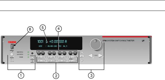
Figure 2-1: Model 3706 System Switch/Multimeter .............................................................. |
2-1 |
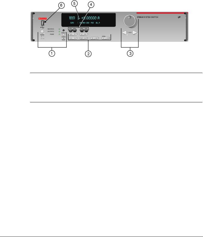
Figure 2-2: Model 3706-S System Switch (no DMM)............................................................ |
2-2 |
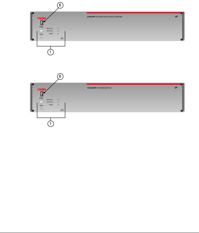
Figure 2-3: Model 3706-NFP System Switch/Multimeter ...................................................... |
2-3 |
Figure 2-4: Model 3706-SNFP System Switch (no DMM)..................................................... |
2-3 |
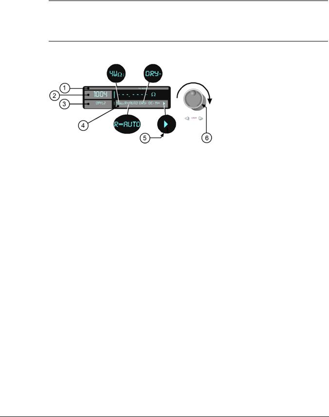
Figure 2-5: Active channel display example......................................................................... |
2-4 |
Figure 2-6: MAIN MENU display.......................................................................................... |
2-6 |
Figure 3-1: Rear panel features........................................................................................... |
3-1 |
Figure 3-2: Digital I/O port ................................................................................................... |
3-3 |
Figure 3-3: USB connectors ................................................................................................ |
3-5 |
Figure 3-4: Analog backplane connector ............................................................................. |
3-5 |
Figure 3-5: Typical module installation................................................................................. |
3-7 |
Figure 4-1: Multiplexer card display..................................................................................... |
4-11 |
Figure 4-2: Matrix card display ............................................................................................ |
4-12 |
Figure 4-3: Two-wire function.............................................................................................. |
4-14 |
Figure 4-4: Four-wire function.............................................................................................. |
4-15 |
Figure 5-1: Line cycle synchronization................................................................................. |
5-4 |
Figure 5-2: DCV connection ................................................................................................ |
5-6 |
Figure 5-3: ACV connection ................................................................................................ |
5-6 |
Figure 5-4: Rear panel to backplane to DMM connect relays schematic............................... |
5-7 |
Figure 5-5: ACV measurements: sine waves ....................................................................... |
5-9 |
Figure 5-6: ACV measurements: square, pulse, and sawtooth waves.................................. |
5-10 |
Figure 5-7: Two-wire resistance measurements .................................................................. |
5-18 |
Figure 5-8: Four-wire resistance measurement.................................................................... |
5-18 |

List of Figures |
System Switch/Multimeter User's Manual |
|
|
|
|
Figure 5-9: Two-wire switching module resistance connection ............................................. |
5-19 |
Figure 5-10: Four-wire switching module resistance connection........................................... |
5-19 |
Figure 5-11: Enabling offset-compensated ohms................................................................. |
5-21 |
Figure 5-12: Four-wire Ohm ATTR MENU: OFFSETCOMP................................................. |
5-22 |
Figure 5-13: Enabling dry-circuit ohms ................................................................................ |
5-24 |
Figure 5-14: Four-wire Ohm ATTR MENU: DRYCIRCUIT.................................................... |
5-24 |
Figure 5-15: Two-wire constant-current source method ....................................................... |
5-27 |
Figure 5-16: Four-wire constant-current source method....................................................... |
5-27 |
Figure 5-17: Two-wire ratiometric method............................................................................ |
5-28 |
Figure 5-18: Four-wire ratiometric method........................................................................... |
5-29 |
Figure 5-19: Simplified Dry-Circuit open lead detection schematic....................................... |
5-30 |
Figure 5-20: Simplified normal four-wire open lead detection schematic .............................. |
5-31 |
Figure 5-21: Simplified Dry-Circuit open V-clamp feedback loop schematic ......................... |
5-34 |
Figure 5-22: Simplified T/C open lead detection schematic.................................................. |
5-38 |
Figure 5-23: Simulated reference junction ........................................................................... |
5-40 |
Figure 5-24: Simulated reference junction switching module................................................ |
5-40 |
Figure 5-25: Internal reference junction (40 channel switching module) ............................... |
5-40 |
Figure 5-26: Thermistor analog backplane connection......................................................... |
5-42 |
Figure 5-27: Thermistor switching module connection ......................................................... |
5-42 |
Figure 5-28: Three-wire RTD connections ........................................................................... |
5-44 |
Figure 5-29: Three-wire RTD switching module connections................................................ |
5-44 |
Figure 5-30: Four-wire RTD connections............................................................................. |
5-45 |
Figure 5-31: Four-wire RTD switching module connections.................................................. |
5-45 |
Figure 5-32: FREQ and PERIOD input connections............................................................. |
5-49 |
Figure 5-33: FREQ and PERIOD connections (switching module) ....................................... |
5-49 |
viii |
Document Number: 3700S-900-01 Rev. A / August 2007 |

System Switch/Multimeter User's Manual |
List of Figures |
|
|
|
|
Figure 5-34: Continuity connections .................................................................................... |
5-51 |
Figure 5-35: Continuity connections using a switching module............................................. |
5-51 |
Figure 8-1: Fuse location..................................................................................................... |
8-2 |
Figure 9-1: Model 3720 ....................................................................................................... |
9-8 |
Figure 9-2: D-sub connection information for the Model 3720 .............................................. |
9-9 |
Figure 9-3: Schematic of the Model 3720 ............................................................................ |
9-10 |
Figure 9-4: Sample Model 3720 connection log (1 of 2) ....................................................... |
9-11 |
Figure 9-5: Sample Model 3720 connection log................................................................... |
9-12 |
Figure 9-6: Model 3721 ....................................................................................................... |
9-13 |
Figure 9-7: D-sub connection information for the Model 3721 .............................................. |
9-15 |
Figure 9-8: Schematic of the Model 3721 in two-pole mode................................................. |
9-16 |
Figure 9-9: Schematic of the Model 3721 in four-wire common side ohm mode ................... |
9-17 |
Figure 9-10: Model 3721 shield removal.............................................................................. |
9-19 |
Figure 9-11: Model 3721 fuse location................................................................................. |
9-19 |
Figure 9-12: Sample Model 3721 connection log (1 of 2) ..................................................... |
9-20 |
Figure 9-13: Sample Model 3721 connection log (2 of 2) ..................................................... |
9-21 |
Figure 9-14: Model 3722 ..................................................................................................... |
9-22 |
Figure 9-15: D-sub connection information the Model 3722 ................................................. |
9-23 |
Figure 9-16: Schematic for the Model 3722 ......................................................................... |
9-24 |
Figure 9-17: Sample Model 3722 connection log (1 of 3) ..................................................... |
9-25 |
Figure 9-18: Sample Model 3722 connection log (2 of 3) ..................................................... |
9-26 |
Figure 9-19: Sample Model 3722 connection log (3 of 3) ..................................................... |
9-27 |
Figure 9-20: Model 3723 ..................................................................................................... |
9-28 |
Figure 9-21: D-sub connection information for the Model 3723 ............................................ |
9-29 |
Figure 9-22: Schematic for the Model 3723 in two-pole mode.............................................. |
9-30 |
Document Number: 3700S-900-01 Rev. A / August 2007 |
ix |

List of Figures |
System Switch/Multimeter User's Manual |
|
|
|
|
Figure 9-23: Schematic: Model 3723 in one-pole mode ....................................................... |
9-31 |
Figure 9-24: Sample Model 3723 connection log (60 channel)(1 of 2).................................. |
9-32 |
Figure 9-25: Sample Model 3723 connection log (60 channel)(2 of 2).................................. |
9-33 |
Figure 9-26: Sample Model 3723 connection log (120 channel)(1 of 4)................................ |
9-34 |
Figure 9-27: Sample Model 3723 connection log (120 channel)(2 of 4)................................ |
9-35 |
Figure 9-28: Sample Model 3723 connection log (120 channel)(3 of 4)................................ |
9-36 |
Figure 9-29: Sample Model 3723 connection log (120 channel)(4 of 4)................................ |
9-37 |
Figure 9-30: Model 3730 ..................................................................................................... |
9-38 |
Figure 9-31: D-sub connection information for the Model 3730 ............................................ |
9-39 |
Figure 9-32: Schematic of the Model 3730 .......................................................................... |
9-39 |
Figure 9-33: Sample Model 3730 connection log (1 of 3) ..................................................... |
9-40 |
Figure 9-34: Sample Model 3730 connection log (2 of 3) ..................................................... |
9-41 |
Figure 9-35: Sample Model 3730 connection log (3 of 3) ..................................................... |
9-42 |
Figure 9-36: Model 3740 ..................................................................................................... |
9-43 |
Figure 9-37: D-sub connection information for the Model 3740 ............................................ |
9-44 |
Figure 9-38: Schematic for the Model 3740 ......................................................................... |
9-45 |
Figure 9-39: Sample Model 3740 connection log................................................................. |
9-46 |
x |
Document Number: 3700S-900-01 Rev. A / August 2007 |

Section 1
Introduction
If you have any questions after reviewing this information, please contact your local Keithley Instruments representative or call one of our Applications Engineers at 1-888-KEITHLEY (1-888-534-8453). You can also contact us through our website at www.keithley.com.
In this section:
Overview ........................................................................................................ |
1-1 |
Warranty information....................................................................................... |
1-3 |
Safety symbols and terms ............................................................................... |
1-4 |
Specifications.................................................................................................. |
1-4 |
Overview
The Series 3700 instruments offer scalable, instrument grade switching and multi-channel measurement solutions that are optimized for automated testing of electronic products and components. The Series 3700 includes four versions of the Model 3706 system switch mainframe along with a growing family of plug-in switch and control cards. When the Model 3706 mainframe is ordered with the high performance multimeter, you receive a tightly integrated switch and measurement system that can meet the demanding application requirements in a functional test system or provide the flexibility needed in stand-alone data acquisition and measurement applications.

Section 1: Introduction |
Series 3700 System Switch/Multimeter User's Manual |
|
|
|
|
Measure and switching capabilities
The basic measurement capabilities of Series 3700 systems are summarized in the following figure.
Figure 1-1: DMM measurement capabilities
Reference manual content
Refer to the Series 3700 Reference Manual for specific listing of advanced operation including:
Range
Digits
Rate Bandwidth
Filter
Relative
Math
dB
Buffer
Scanning
Calibration
Also included in the reference manual is a detailed listing of the Instrument Control Library (ICL) commands.
1-2 |
Document Number: 3700S-900-01 Rev. A / August 2007 |
Series 3700 System Switch/Multimeter User's Manual |
Section 1: Introduction |
|
|
|
|
Warranty information
Detailed warranty information is located at the front of this manual. Should your Series 3700 require warranty service, contact the Keithley Instruments representative or authorized repair facility in your area for further information. When returning the instrument for repair, be sure to complete the service form at the back of this manual and give it to the repair facility with all relevant information.
NOTE The service form requires the serial number of the Series 3700. The serial number label is located inside the unit on the bottom panel. The serial number can be viewed by removing the slot covers and/or switching modules from the mainframe.
WARNING |
Before removing (or installing) switching modules, make sure you turn off |
|
the Series 3700 and disconnect the line cord. Also, remove any other |
|
external power connected to the instrument or switching module(s). |
|
Failure to remove power before removing (or installing) switching |
|
modules may result in personal injury or death due to electric shock. |
|
|
Displaying the unit's serial number
To display the serial number on the front panel:
NOTE If the Series 3700 is in remote mode, press the EXIT key once to place the unit in local mode.
1.When in local mode, press the MENU key.
2.Scroll to the SYSTEM-INFO menu and press the ENTER key.
3.On the SYSTEM INFORMATION menu, scroll to the SERIAL# and press the ENTER key. The Series 3700 serial number will be displayed.
Document Number: 3700S-900-01 Rev. A / August 2007 |
1-3 |

Section 1: Introduction |
Series 3700 System Switch/Multimeter User's Manual |
|
|
|
|
Safety symbols and terms
The following symbols and terms may be found on the System Switch/Multimeter or used in this manual:
The 

 symbol indicates that the user should refer to the operating instructions located in the manual.
The 


 symbol shows that high voltage may be present on the terminal(s). Use standard safety precautions to avoid personal contact with these voltages.
The 


 symbol on an instrument shows that the surface may be hot. Avoid personal contact to prevent burns.
The WARNING heading used in this manual explains dangers that might result in personal injury or death. Always read the associated information very carefully before performing the indicated procedure.
The CAUTION heading used in this manual explains hazards that could damage the unit. Such damage may invalidate the warranty.
Specifications
Full specifications can be found in Appendix A of this manual. Also, refer to the product data sheet for System Switch/Multimeter specifications. Check the Keithley Instruments website at www.keithley.com for the latest updates to the specifications.
1-4 |
Document Number: 3700S-900-01 Rev. A / August 2007 |
|
|
Section 2 |
|
|
|
|
|
|
|
Using the Front Panel |
|
|
In this section: |
|
|
|
Front panel introduction |
................................................................................... 2-1 |
|
|
Display ........................................................................................................... |
2-3 |
|
|
Front panel keys ............................................................................................. |
2-6 |
|
Front panel introduction
Typical Series 3700 front panels are shown below.
NOTE Not all models will have a DMM installed. All DMM related documentation is not applicable to those models.
Figure 2-1: Model 3706 System Switch/Multimeter
Item |
Description |
|
|
1 |
Special keys and power switch (on page 2-6) |
|
|
2 |
Operation keys (on page 2-7) |
|
|
3 |
Range, multifunction keys, and wheel (on page 2-17) |
|
|
4 |
Function keys (on page 2-17) |
|
|
5 |
Display (on page 2-3) |
|
|
6 |
USB connector (see "USB connectors" on page 3-4) |
|
|
Section 2: Using the Front Panel |
Series 3700 System Switch/Multimeter User's Manual |
|
|
|
|
Figure 2-2: Model 3706-S System Switch (no DMM)
NOTE If your model does not have a front panel, please refer to the reference manual for information on how to change:
1.GPIB address with gpib.address command.
2.LAN configuration using LAN functions. To see current settings for LAN, see the applicable lan.status.* commands (for example, to see the present IP address of the Series 3700, send the following command: lan.status.ipaddress.
2-2 |
Document Number: 3700S-900-01 Rev. A / August 2007 |
Series 3700 System Switch/Multimeter User's Manual |
Section 2: Using the Front Panel |
|
|
|
|
Figure 2-3: Model 3706-NFP System Switch/Multimeter
Figure 2-4: Model 3706-SNFP System Switch (no DMM)
Display
The Series 3700 display provides visual information on the present active channel. The display, with the wheel, provides a means to change the active channel or channel ranges, as well as access to view and edit the various menus and menu items.
See the following figure for an active channel example. The display has the 4W and AUTO range annunciators lit (1). Also, the active channel is 1004 (Slot 1 Channel 004). The present state of the channel is open, and it has two poles (3). The present state of the attributes for this channel (4) are: 4W function set for AUTO range, dry-circuit ohms disabled (DRY-), offset compensation off (OC-). Other attributes, such as NPLC, are available for this specific active channel (1004) as indicated by arrow (5) being lit. These may be viewed by turning the wheel (6) to scroll through the attribute list.
Document Number: 3700S-900-01 Rev. A / August 2007 |
2-3 |
Section 2: Using the Front Panel |
Series 3700 System Switch/Multimeter User's Manual |
|
|
|
|
NOTE Attribute lists, as well as menu lists, that are larger than the display, can be accessed by turning the wheel (6). Displayed arrows (5) indicate additional attributes (or menu items, as applicable) are available for access by turning the wheel (6) in the direction the arrow points. If an arrow (5) is not displayed, there are no additional menu choices in that direction.
Figure 2-5: Active channel display example
The top line of the display (1) contains the following annunciators:
Annunciator |
Description |
|
|
* (asterisk) |
Front panel readings are being stored in the selected reading buffer. |
|
|
4W |
4-wire resistance or RTD temperature reading displayed. |
|
|
ARM |
Unit armed and ready to use. |
|
|
AUTO |
Auto range enabled for the selected DMM function. |
|
|
EDIT |
Unit in edit mode (for front panel). |
|
|
FILT |
Filter enabled for the selected DMM function. |
|
|
LSTN |
Instrument addressed to listen over GPIB. |
|
|
MATH |
mX+b, percent, or reciprocal (1/X) calculation enabled for the selected DMM function. |
|
|
REL |
Relative enabled for selected DMM function. |
|
|
REM |
Instrument in bus remote mode or web control mode (all interfaces, LAN, GPIB, or |
|
USB). |
|
|
SMPL |
Flashes whenever the DMM has completed a reading. |
|
|
SRQ |
Service request over GPIB. |
|
|
TALK |
Instrument addressed to talk over GPIB bus. |
|
|
TRIG |
External triggering selected. The TRIG annunciator will blink if taking continuous |
|
triggered readings on front panel. |
|
|
2-4 |
Document Number: 3700S-900-01 Rev. A / August 2007 |

Series 3700 System Switch/Multimeter User's Manual |
Section 2: Using the Front Panel |
|
|
|
|
The bottom line of the display (4) contains the attribute symbols. The symbols that appear are dependent on whether the attribute exists for the selected function. If the symbol has also contains a value, the third column in the table indicates the value definition. The following table indicates the DMM attribute symbols that may appear on the front panel.
Front panel DMM attribute |
Symbol |
Values |
|
|
|
range |
R= |
AUTO or n, here n equals the range |
|
|
|
nplc |
N= |
n, where n equals the nplc |
|
|
|
auto delay |
AD |
+ for ON, 1 for ONCE, or 0 for OFF |
|
|
|
auto zero |
AZ |
+ for ON or – for OFF |
|
|
|
line sync |
LS |
+ for ON or – for OFF |
|
|
|
limit |
LIM |
+ for a limit enabled or – for limits disabled |
|
|
|
detector bandwidth |
DBW |
3, 30, or 300 |
|
|
|
threshold |
THR= |
n, where n indicates the threshold |
|
|
|
aperture |
A= |
n, where n indicates the aperture setting |
|
|
|
dry circuit |
DRY |
+ for ON or – for OFF |
|
|
|
offset compensation |
OC |
+ for ON or – for OFF |
|
|
|
thermocouple sensor K |
K_T/C |
N/A |
|
|
|
thermocouple sensor T |
T_T/C |
N/A |
|
|
|
thermocouple sensor E |
E_T/C |
N/A |
|
|
|
thermocouple sensor R |
R_T/C |
N/A |
|
|
|
thermocouple sensor S |
S_T/C |
N/A |
|
|
|
thermocouple sensor B |
B_T/C |
N/A |
|
|
|
thermocouple sensor N |
N_T/C |
N/A |
|
|
|
thermistor |
THRM |
N/A |
|
|
|
three-wire RTD |
3RTD |
N/A |
|
|
|
four-wire RTD |
4RTD |
N/A |
|
|
|
simulated reference junction |
RJ_SIM |
N/A |
|
|
|
internal reference junction |
RJ_INT |
N/A |
|
|
|
external reference junction |
RJ_EXT |
N/A |
|
|
|
NOTE To access the main menu, press the MENU key.
Document Number: 3700S-900-01 Rev. A / August 2007 |
2-5 |

Section 2: Using the Front Panel |
Series 3700 System Switch/Multimeter User's Manual |
|
|
|
|
See the following figure for a menu example. In the example, the MAIN MENU is displayed. Turn the wheel (6) or press the cursor keys, to scroll through the available menu items. In the following figure's first display, there is a right arrow indicator. This indicates there are additional menu items to the right. In figure's second display, both right and left arrows are active indicating there are additional items in both directions. To select the highlighted (flashing) menu item, press the wheel (or press the ENTER key).
Figure 2-6: MAIN MENU display
Front panel keys
Special keys and power switch
POWER switch
Press this switch to turn the Series 3700 on (I); press it again to turn it off (O).
DISPLAY key
Press this key to toggles between main and user display modes.
2-6 |
Document Number: 3700S-900-01 Rev. A / August 2007 |

Series 3700 System Switch/Multimeter User's Manual |
Section 2: Using the Front Panel |
|
|
|
|
CONFIG key
Use this key to access the an attribute menu that enables you to configure channels, channel patterns, DMM functions, or settings, reading buffer, scans, and other operations. Refer to the following for additional information:
CHAN key configuration (on page 2-8)
PATT key configuration (on page 2-9)
SCAN key configuration (on page 2-10)
DMM key configuration (on page 2-11)
LIMIT key configuration (on page 2-14)
REL key configuration (on page 2-14)
FILTER key configuration (on page 2-15)
RESET switch
Use this switch to restore the Series 3700 factory default LAN settings. Refer to the reference manual LAN functions (lan.config.x, where x represents the specific command) for factory default information.
Operation keys
CHAN key
Pressing this key opens the CHANNEL ACTION MENU that contains the following menu items:
OPEN: This menu item opens the specified channels for switching aspects. Related Instrument Control Library (ICL) command: channel.open
CLOSE: This menu item closes specified channels. These closures are appended to the already closed channels. Related ICL command: channel.close
EXCLOSE: This menu item closes the specified items so they are exclusively closed. Related ICL commands: channel.exclusiveclose, channel.exclusiveslotclose
EXSLOTCLOSE: This menu item exclusively closes specified channels on the specified slots. Related ICL command: channel.exclusiveslotclose
RESET: This menu item resets channel and channel pattern aspects of the system to factory default settings. Related ICL command: channel.reset
Document Number: 3700S-900-01 Rev. A / August 2007 |
2-7 |

Section 2: Using the Front Panel |
Series 3700 System Switch/Multimeter User's Manual |
|
|
|
|
CHAN key configuration
Pressing the CONFIG key and then the CHAN key opens the CHANNEL ATTRibute MENU. This menu contains:
LABEL: This menu item sets the label associated with the channels specified. Related ICL command: channel.setlabel. From the front panel, the label can be up to 12 characters. Remotely, the label may be up to 20 characters.
BACKPLANE: This menu item opens the BACKPLANE MENU. Use this menu to add or remove backplane channels from the channels specified. Related ICL command: channel.setbackplane
FORBID: This menu item prevents the closing of the channels specified. Related ICL command: channel.setforbidden
POLE: This menu item sets the number of poles for the channels specified. Related ICL command: channel.setpole
DELAY: This menu sets additional delay time for channels specified. Related ICL command: channel.setdelay
COUNT: This menu item displays closure cycles for the channels specified. Related ICL command: channel.getcount
DMM_CONFIG: This menu item sets the DMM configuration associated with the channels specified. Related ICL command: dmm.setconfig
PATT key
Pressing this key opens the PATTERN ACTION MENU that contains the following menu items:
OPEN: This menu item opens the specified channel pattern for switching aspects. Related ICL command: channel.open
CLOSE: This menu item closes specified channel pattern. These closures are appended to the already closed channels. Related ICL command: channel.close
EXCLOSE: This menu item closes the specified items so they are exclusively closed. Related ICL command: channel.exclusiveclose
EXSLOTCLOSE: This menu item exclusively closes specified channels on the specified slots. Related ICL command: channel.exclusiveslotclose
CREATE: This menu item creates a channel pattern from a snapshot and associates it with the specified name. From the front panel, the pattern name can be up to 12 characters. Remotely, the pattern name may be up to 20 characters. Note that if no patterns exist in the system when the PATT key is pressed, then CREATE will be the only menu item displayed. Related ICL commands: channel.pattern.snapshot
2-8 |
Document Number: 3700S-900-01 Rev. A / August 2007 |
Loading...