


 Loading...
www.keithley.com
Model 2281S-20-6
Precision DC Supply And Battery Simulator
Reference Manual
077114600 / August 2015
*P077114600*
077114600
A Tektr onix Company
Model 2281S-20-6
Precision DC Supply And Battery Simulator
Reference Manual
© 2015, Keithley Instruments
Cleveland, Ohio, U.S.A. All rights reserved.
Any unauthorized reproduction, photocopy, or use of the information herein, in whole or in part, without the prior written approval of Keithley Instruments is strictly prohibited.
All Keithley Instruments product names are trademarks or registered trademarks of Keithley Instruments. Other brand names are trademarks or registered trademarks of their respective holders.
Document number: 077114600 / August 2015

Safety precautions
The following safety precautions should be observed before using this product and any associated instrumentation. Although some instruments and accessories would normally be used with nonhazardous voltages, there are situations where hazardous conditions may be present.
This product is intended for use by qualified personnel who recognize shock hazards and are familiar with the safety precautions required to avoid possible injury. Read and follow all installation, operation, and maintenance information carefully before using the product. Refer to the user documentation for complete product specifications.
If the product is used in a manner not specified, the protection provided by the product warranty may be impaired.
The types of product users are:
Responsible body is the individual or group responsible for the use and maintenance of equipment, for ensuring that the equipment is operated within its specifications and operating limits, and for ensuring that operators are adequately trained.
Operators use the product for its intended function. They must be trained in electrical safety procedures and proper use of the instrument. They must be protected from electric shock and contact with hazardous live circuits.
Maintenance personnel perform routine procedures on the product to keep it operating properly, for example, setting the line voltage or replacing consumable materials. Maintenance procedures are described in the user documentation. The procedures explicitly state if the operator may perform them. Otherwise, they should be performed only by service personnel.
Service personnel are trained to work on live circuits, perform safe installations, and repair products. Only properly trained service personnel may perform installation and service procedures.
Keithley Instruments products are designed for use with electrical signals that are measurement, control, and data I/O connections, with low transient overvoltages, and must not be directly connected to mains voltage or to voltage sources with high transient overvoltages. Measurement Category II (as referenced in IEC 60664) connections require protection for high transient overvoltages often associated with local AC mains connections. Certain Keithley measuring instruments may be connected to mains. These instruments will be marked as category II or higher.
Unless explicitly allowed in the specifications, operating manual, and instrument labels, do not connect any instrument to mains.
Exercise extreme caution when a shock hazard is present. Lethal voltage may be present on cable connector jacks or test fixtures. The American National Standards Institute (ANSI) states that a shock hazard exists when voltage levels greater than 30 V RMS, 42.4 V peak, or 60 VDC are present. A good safety practice is to expect that hazardous voltage is present in any unknown circuit before measuring.
Operators of this product must be protected from electric shock at all times. The responsible body must ensure that operators are prevented access and/or insulated from every connection point. In some cases, connections must be exposed to potential human contact. Product operators in these circumstances must be trained to protect themselves from the risk of electric shock . If the circuit is capable of operating at or above 1000 V, no conductive part of the circuit may be exposed.
Do not connect switching cards directly to unlimited power circuits. They are intended to be used with impedance-limited sources. NEVER connect switching cards directly to AC mains. When connecting sources to switching cards, install protective devices to limit fault current and voltage to the card.
Before operating an instrument, ensure that the line cord is connected to a properly-grounded power receptacle. Inspect the connecting cables, test leads, and jumpers for possible wear, cracks, or breaks before each use.
When installing equipment where access to the main power cord is restricted, such as rack mounting, a separate main input power disconnect device must be provided in close proximity to the equipment and within easy reach of the operator.
For maximum safety, do not touch the product, test cables, or any other instruments while power is applied to the circuit under test. ALWAYS remove power from the entire test system and discharge any capacitors before: connecting or disconnecting cables or jumpers, installing or removing switching cards, or making internal changes, such as installing or removing jumpers .
Do not touch any object that could provide a current path to the common side of the circuit under test or power line (earth) ground. Always make measurements with dry hands while standing on a dry, insulated surface capable of withstanding the voltage being measured.
For safety, instruments and accessories must be used in accordance with the operating instructions. If the instruments or

accessories are used in a manner not specified in the operating instructions, the protection provided by the equipment may be impaired.
Do not exceed the maximum signal levels of the instruments and accessories, as defined in the specifications and operating information, and as shown on the instrument or test fixture panels, or switching card.
When fuses are used in a product, replace with the same type and rating for continued protection against fire hazard.
Chassis connections must only be used as shield connections for measuring circuits, NOT as protective earth (safety ground) connections.
If you are using a test fixture, keep the lid closed while power is applied to the device under test. Safe operation requires the use of a lid interlock.
If a  screw is present, connect it to protective earth (safety ground) using the wire recommended in the user documentation.
The  symbol on an instrument means caution, risk of danger. The user must refer to the operating instructions located in the user documentation in all cases where the symbol is marked on the instrument.
The  symbol on an instrument means caution, risk of electric shock. Use standard safety precautions to avoid personal contact with these voltages.
The |
symbol on an instrument shows that the surface may be hot. Avoid personal contact to prevent burns. |
The  symbol indicates a connection terminal to the equipment frame.
If this  symbol is on a product, it indicates that mercury is present in the display lamp. Please note that the lamp must be properly disposed of according to federal, state, and local laws.
The WARNING heading in the user documentation explains dangers that might result in personal injury or death. Always read the associated information very carefully before performing the indicated procedure.
The CAUTION heading in the user documentation explains hazards that could damage the instrument. Such damage may invalidate the warranty.
Instrumentation and accessories shall not be connected to humans.
Before performing any maintenance, disconnect the line cord and all test cables.
To maintain protection from electric shock and fire, replacement components in mains circuits — including the power transformer, test leads, and input jacks — must be purchased from Keithley Instruments. Standard fuses with applicable national safety approvals may be used if the rating and type are the same. Other components that are not safety-related may be purchased from other suppliers as long as they are equivalent to the original component (note that selected parts should be purchased only through Keithley Instruments to maintain accuracy and functionality of the product). If you are unsure about the applicability of a replacement component, call a Keithley Instruments office for information.
To clean an instrument, use a damp cloth or mild, water-based cleaner. Clean the exterior of the instrument only. Do not apply cleaner directly to the instrument or allow liquids to enter or spill on the instrument. Products that consist of a circuit board with no case or chassis (e.g., a data acquisition board for installation into a computer) should never require cleaning if handled according to instructions. If the board becomes contaminated and operation is affected, the board should be returned to the factory for proper cleaning/servicing.
Safety precaution revision as of January 2013.
|
Table of Contents |
|
|
Introduction .......................................................................................................... |
1-1 |
Welcome ......................................................................................................................... |
1-1 |
Extended warranty........................................................................................................... |
1-1 |
Contact information ......................................................................................................... |
1-1 |
CD-ROM contents ........................................................................................................... |
1-2 |
Organization of manual sections...................................................................................... |
1-3 |
Key features .................................................................................................................... |
1-4 |
Standard accessories ...................................................................................................... |
1-4 |
Optional accessories ....................................................................................................... |
1-6 |
Available services............................................................................................................ |
1-6 |
General ratings................................................................................................................ |
1-7 |
New terms in 2281S-20-6 ................................................................................................ |
1-7 |
General operation ................................................................................................. |
2-1 |
Front panel overview ....................................................................................................... |
2-1 |
Rear-panel overview........................................................................................................ |
2-3 |
Front-panel user interface................................................................................................ |
2-4 |
Startup screen........................................................................................................................... |
2-4 |
Home screens........................................................................................................................... |
2-5 |
Power supply menu overview.................................................................................................. |
2-17 |
Battery test menu overview ..................................................................................................... |
2-27 |
Battery simulator menu overview ............................................................................................ |
2-33 |
Adjusting the backlight brightness and timer........................................................................... |
2-37 |
Installing the system ...................................................................................................... |
2-37 |
Handle and bumpers............................................................................................................... |
2-37 |
Dimensions ............................................................................................................................. |
2-42 |
Power the instrument on and off ............................................................................................. |
2-46 |
Test connections ........................................................................................................... |
2-49 |
Front-panel connector............................................................................................................. |
2-49 |
Rear-panel output mating connector ....................................................................................... |
2-50 |
Two-wire local sense connection ............................................................................................ |
2-50 |
Four-wire sense connection .................................................................................................... |
2-51 |
Open leads detection .............................................................................................................. |
2-53 |
Reverse sense leads............................................................................................................... |
2-54 |
Remote communication interfaces ................................................................................. |
2-55 |
Supported remote interfaces................................................................................................... |
2-55 |
GPIB communication .............................................................................................................. |
2-56 |
LAN communication................................................................................................................ |
2-59 |
USB communications.............................................................................................................. |
2-73 |
How to install the Keithley I/O Layer ....................................................................................... |
2-77 |
Set voltage and current limit........................................................................................... |
2-78 |
Constant voltage (CV) and constant current (CC) mode......................................................... |
2-79 |
Select a measurement function...................................................................................... |
2-80 |
Table of Contents |
Model 2281S - 20 - 6 Precision DC Supply And Battery Simulator Reference Manual |
|
Select a measurement function |
............................................................................................... |
2-81 |
Battery test.............................................................................................................................. |
|
2-81 |
Battery simulator ..................................................................................................................... |
|
2-81 |
Select a specific measurement range ............................................................................ |
2-82 |
|
Selecting a specific measurement ................................................................................range |
2-82 |
|
Using Autoranging for Current Measurements ........................................................................ |
2-83 |
|
Protection ...................................................................................................................... |
|
2-84 |
Overvoltage protection ............................................................................................................ |
|
2-84 |
Overcurrent protection ............................................................................................................ |
|
2-86 |
Overtemperature protection .................................................................................................... |
|
2-86 |
Overprotection error ................................................................................................................ |
|
2-87 |
Maximum voltage limits........................................................................................................... |
|
2-88 |
Saving setups................................................................................................................ |
|
2-88 |
Save a user setup ................................................................................................................... |
|
2-89 |
Recall a user setup ................................................................................................................. |
|
2-90 |
Specify a default setup............................................................................................................ |
|
2-90 |
Using the event log........................................................................................................ |
|
2-91 |
Information provided for each event .........................................................................log entry |
2-91 |
|
Save the event log to an external ...........................................................................flash drive |
2-91 |
|
Clear the event log .................................................................................................................. |
|
2-91 |
System information........................................................................................................ |
|
2-92 |
Instrument sounds......................................................................................................... |
|
2-92 |
Resets........................................................................................................................... |
|
2-93 |
Reset the instrument............................................................................................................... |
|
2-93 |
Functions and features......................................................................................... |
|
3-1 |
Instrument access ........................................................................................................... |
|
3-1 |
Changing the instrument access .....................................................................................mode |
3-2 |
|
Changing the password ............................................................................................................ |
|
3-2 |
Graph.............................................................................................................................. |
|
3-2 |
Changing the window position and ..................................................................................zoom |
3-3 |
|
Adjusting the scale and offset of ....................................................................................Y-Axis |
3-6 |
|
Output delay, slew rate, and source ........................................................................delay |
3-7 |
|
Output delay.............................................................................................................................. |
|
3-8 |
Slew rate ................................................................................................................................... |
|
3-8 |
Source delay ............................................................................................................................. |
|
3-9 |
Data buffer .................................................................................................................... |
|
3-10 |
Effects of reset and power cycle ..............................................................................on buffer |
3-10 |
|
Buffer fill status........................................................................................................................ |
|
3-10 |
Setting reading buffer size and ............................................................................buffer mode |
3-11 |
|
Viewing and saving buffer content .......................................................................................... |
3-12 |
|
Configuring the statistics applied .............................................................to data in the buffer |
3-15 |
|
Clearing buffer......................................................................................................................... |
|
3-18 |
Automatically clearing buffer ................................................................................................... |
|
3-19 |
Digital I/O ...................................................................................................................... |
|
3-19 |
Digital I/O port ......................................................................................................................... |
|
3-19 |
Configuring digital I/O lines ..................................................................................................... |
|
3-24 |
Trigger model ................................................................................................................ |
|
3-27 |
Idle and initiate........................................................................................................................ |
|
3-29 |
Arm layer................................................................................................................................. |
|
3-29 |
Trigger layer............................................................................................................................ |
|
3-29 |
Model 2281S-20-6 Precision DC Supply And Battery Simulator Reference Manual |
Table of Contents |
Source, source delay and measure actions ............................................................................ |
3-29 |
Counter ................................................................................................................................... |
3-30 |
Meter complete ....................................................................................................................... |
3-30 |
Running the trigger model....................................................................................................... |
3-30 |
Level trigger .................................................................................................................. |
3-32 |
Configuring a voltage level trigger........................................................................................... |
3-32 |
Configuring a current level trigger ........................................................................................... |
3-34 |
List operation................................................................................................................. |
3-36 |
Configuring a list ..................................................................................................................... |
3-37 |
Importing a list from an external USB flash drive .................................................................... |
3-39 |
Exporting a list to an external USB flash drive ........................................................................ |
3-40 |
Running a list .......................................................................................................................... |
3-40 |
Aborting a list .......................................................................................................................... |
3-49 |
Sink operation ............................................................................................................... |
3-50 |
Battery charging & discharging ...................................................................................... |
3-51 |
Battery discharging test........................................................................................................... |
3-52 |
Battery charging test ............................................................................................................... |
3-54 |
Generating and editing battery model ............................................................................ |
3-56 |
Generating a battery model..................................................................................................... |
3-57 |
Editing a battery model ........................................................................................................... |
3-57 |
Battery simulation .......................................................................................................... |
3-58 |
Battery simulation settings ...................................................................................................... |
3-58 |
Simulating a battery ................................................................................................................ |
3-59 |
Reset default values ...................................................................................................... |
3-60 |
Math and statistics reset values .............................................................................................. |
3-60 |
Calibration reset values........................................................................................................... |
3-61 |
Digital I/O reset values ............................................................................................................ |
3-61 |
Display reset values ................................................................................................................ |
3-61 |
Format reset values ................................................................................................................ |
3-62 |
Output reset values ................................................................................................................. |
3-62 |
Measurement reset values...................................................................................................... |
3-63 |
Source reset values ................................................................................................................ |
3-64 |
Status model reset values....................................................................................................... |
3-65 |
Trigger reset values ................................................................................................................ |
3-65 |
Buffer reset values .................................................................................................................. |
3-66 |
Battery test source reset values .............................................................................................. |
3-66 |
Battery test measure reset values........................................................................................... |
3-67 |
Battery simulation reset values ............................................................................................... |
3-68 |
Measurement optimization ................................................................................... |
4-1 |
Introduction ..................................................................................................................... |
4-1 |
Optimizing either measurement accuracy or speed .......................................................... |
4-1 |
Resolution ................................................................................................................................. |
4-2 |
NPLC ........................................................................................................................................ |
4-4 |
Autozero measurements ........................................................................................................... |
4-5 |
Displayed digits......................................................................................................................... |
4-6 |
Filtering measurement data....................................................................................................... |
4-7 |
Math calculations that you can apply to measurements.................................................. |
4-10 |
mx+b ....................................................................................................................................... |
4-10 |
Setting mx+b math operations ................................................................................................ |
4-11 |
Relative offset................................................................................................................ |
4-12 |
Establishing a relative offset value .......................................................................................... |
4-12 |

Table of Contents Model 2281S-20-6 Precision DC Supply And Battery Simulator Reference Manual
Displayed measurements .............................................................................................. |
4-14 |
Select the source of readings.................................................................................................. |
4-15 |
ESR measurement ........................................................................................................ |
4-16 |
Introduction to the ESR measurement .................................................................................... |
4-16 |
Measuring ESR in the battery test function ............................................................................. |
4-18 |
A-H measurement ......................................................................................................... |
4-18 |
Introduction to the A-H measurement ..................................................................................... |
4-19 |
Measuring A-H in the battery test function .............................................................................. |
4-20 |
Application examples ........................................................................................... |
5-1 |
Simple voltage output and current measurement ............................................................. |
5-1 |
Equipment required................................................................................................................... |
5-1 |
Set up remote communications................................................................................................. |
5-1 |
Device connections................................................................................................................... |
5-2 |
Set the voltage and current limit................................................................................................ |
5-2 |
Configure and execute a 10-step linear list sweep............................................................ |
5-3 |
Equipment required................................................................................................................... |
5-3 |
Set up remote communications................................................................................................. |
5-4 |
Device connections................................................................................................................... |
5-4 |
Configure a 10-step linear list sweep ........................................................................................ |
5-4 |
Execute a 10-step linear list sweep........................................................................................... |
5-5 |
Perform a fast current load measurement ........................................................................ |
5-6 |
Equipment required................................................................................................................... |
5-7 |
Set up remote communications................................................................................................. |
5-7 |
Device connections................................................................................................................... |
5-8 |
Measure the fast current load changes ................................................................................... |
5-10 |
Battery test .................................................................................................................... |
5-12 |
Equipment required................................................................................................................. |
5-12 |
Device connections................................................................................................................. |
5-12 |
Test a battery and generate a battery model........................................................................... |
5-13 |
Battery simulation test ................................................................................................... |
5-15 |
Equipment required................................................................................................................. |
5-15 |
Device connections................................................................................................................. |
5-15 |
Simulate a battery with 2281S-20-6 ........................................................................................ |
5-16 |
Explanations of the test........................................................................................................... |
5-17 |
Introduction to SCPI commands........................................................................... |
6-1 |
Introduction to SCPI ........................................................................................................ |
6-1 |
Command messages ................................................................................................................ |
6-1 |
Command execution rules......................................................................................................... |
6-2 |
SCPI command programming notes ................................................................................ |
6-2 |
SCPI command formatting ........................................................................................................ |
6-2 |
Using the SCPI command reference......................................................................................... |
6-4 |
SCPI command reference ..................................................................................... |
7-1 |
Common commands........................................................................................................ |
7-2 |
*CLS.......................................................................................................................................... |
7-2 |
*ESE ......................................................................................................................................... |
7-3 |
*ESR? ....................................................................................................................................... |
7-4 |
*IDN? .............................................................................................................................. |
7-4 |
Model 2281S-20-6 Precision DC Supply And Battery Simulator Reference Manual |
Table of Contents |
*OPC......................................................................................................................................... |
7-5 |
*LANG?..................................................................................................................................... |
7-5 |
*RCL ......................................................................................................................................... |
7-6 |
*RST ......................................................................................................................................... |
7-6 |
*SAV ......................................................................................................................................... |
7-7 |
*SRE ......................................................................................................................................... |
7-7 |
*STB?........................................................................................................................................ |
7-8 |
*TRG ......................................................................................................................................... |
7-9 |
*TST?........................................................................................................................................ |
7-9 |
*WAI........................................................................................................................................ |
7-10 |
:ABORt[n]................................................................................................................................ |
7-11 |
:CONFigure[n]:<function> ....................................................................................................... |
7-11 |
:ENTRy[n]:FUNCtion............................................................................................................... |
7-12 |
:FETCh[n]?.............................................................................................................................. |
7-13 |
:FORMat:ELEMents................................................................................................................ |
7-13 |
:FORCe:TRIGger .................................................................................................................... |
7-15 |
:MEASure[n]:<function>? ........................................................................................................ |
7-16 |
:READ[n]? ............................................................................................................................... |
7-17 |
ARM subsystem ............................................................................................................ |
7-17 |
:ARM[:SEQuence[n]]:COUNt .................................................................................................. |
7-18 |
:ARM[:SEQuence[n]]:SOURce................................................................................................ |
7-18 |
BATTery subsystem ...................................................................................................... |
7-19 |
:BATTery[n]:SIMulator:SOC .................................................................................................... |
7-19 |
:BATTery[n]:SIMulator:VOC .................................................................................................... |
7-20 |
:BATTery[n]:SIMulator:VOC:FULL .......................................................................................... |
7-21 |
:BATTery[n]:SIMulator:VOC:EMPTy ....................................................................................... |
7-22 |
:BATTery[n]:SIMulator:VOC:PROTection[:LEVel]................................................................... |
7-23 |
BATTery[n]:SIMulator:RESistance?........................................................................................ |
7-23 |
:BATTery[n]:SIMulator:RESistance:OFFSet............................................................................ |
7-24 |
:BATTery[n]:SIMulator:CAPacity? ........................................................................................... |
7-25 |
:BATTery[n]:SIMulator:CAPacity:LIMit .................................................................................... |
7-25 |
:BATTery[n]:SIMulator:CURRent? .......................................................................................... |
7-26 |
:BATTery[n]:SIMulator:CURRent:LIMit.................................................................................... |
7-27 |
:BATTery[n]:SIMulator:CURRent:PROTection[:LEVel] ........................................................... |
7-28 |
:BATTery[n]:SIMulator:TVOLtage? ......................................................................................... |
7-28 |
:BATTery[n]:SIMulator:HV....................................................................................................... |
7-29 |
:BATTery[n]:SIMulator:LV ....................................................................................................... |
7-30 |
:BATTery[n]:SIMulator:SAMPle:INTerval ................................................................................ |
7-30 |
:BATTery[n]:SIMulator:METHod.............................................................................................. |
7-31 |
:BATTery[n]:TEST:MEASure:EVOC? ..................................................................................... |
7-32 |
:BATTery[n]:TEST[:SOURce]:VOLTage[:LEVel]..................................................................... |
7-32 |
:BATTery[n]:TEST[:SOURce]:VOLTage:LIMit......................................................................... |
7-33 |
:BATTery[n]:TEST[:SOURce]:VOLTage:PROTection[:LEVel]................................................. |
7-34 |
:BATTery[n]:TEST[:SOURce]:HV............................................................................................ |
7-35 |
:BATTery[n]:TEST[:SOURce]:LV ............................................................................................ |
7-36 |
:BATTery[n]:TEST[:SOURce]:CURRent:LIMit:SOURce.......................................................... |
7-36 |
:BATTery[n]:TEST[:SOURce]:CURRent:LIMit:SINK ............................................................... |
7-37 |
:BATTery[n]:TEST[:SOURce]:CURRent:END ......................................................................... |
7-38 |
:BATTery[n]:TEST[:SOURce]:CURRent:PROTection[:LEVel]................................................. |
7-38 |
:BATTery[n]:TEST:SENSe:SAMPle:INTerval .......................................................................... |
7-39 |
:BATTery[n]:TEST:SENSe:ESR:DELAy.................................................................................. |
7-40 |
:BATTery[n]:TEST:SENSe:AH[:LEVel]?.................................................................................. |
7-40 |
:BATTery[n]:TEST:SENSe:AH:ESRInterval ............................................................................ |
7-41 |
:BATTery[n]:TEST:SENSe:AH:VFULl ..................................................................................... |
7-41 |
:BATTery[n]:TEST:SENSe:AH:ILIMit ...................................................................................... |
7-42 |
:BATTery[n]:TEST:SENSe:AH:GMODel:RANGe .................................................................... |
7-43 |
:BATTery[n]:TEST:SENSe:AH:GMODel:SAVE:INTErnal........................................................ |
7-44 |
:BATTery[n]:TEST:SENSe:AH:GMODel:SAVE:USB .............................................................. |
7-45 |
:BATTery[n]:TEST:SENSe:AH:END........................................................................................ |
7-46 |
:BATTery[n]:TEST:SENSe:AH:EXECute ................................................................................ |
7-46 |
Table of Contents |
Model 2281S-20-6 Precision DC Supply And Battery Simulator Reference Manual |
|
:BATTery[n]:MODel<model_index>:<element>....................................................................... |
7-47 |
|
:BATTery[n]:MODel<model_index>:<element>:APPEnd ........................................................ |
7-48 |
|
:BATTery[n]:MODel<model_index>:<element>:STEPs? ........................................................ |
7-49 |
|
:BATTery[n]:MODel<model_index>:<element>:SIMPlify ........................................................ |
7-50 |
|
:BATTery[n]:MODel<model_index>:ROW<row_index> .......................................................... |
7-51 |
|
:BATTery[n]:MODel:RCL......................................................................................................... |
|
7-51 |
:BATTery[n]:MODel:SAVE:INTErnal ....................................................................................... |
7-52 |
|
:BATTery[n]:MODel:SAVE:USB.............................................................................................. |
|
7-53 |
:BATTery[n]:MODel:LOAD:USB.............................................................................................. |
|
7-53 |
:BATTery:DIGital:LINE<line_index>:CONFigure..................................................................... |
7-54 |
|
:BATTery:DIGital:LINE<n>:EDGe ........................................................................................... |
7-55 |
|
:BATTery:DIGital:LINE<n>:MANual:INPut:DATA?.................................................................. |
7-56 |
|
:BATTery[n]:TRACe|DATA:DATA? ......................................................................................... |
7-57 |
|
:BATTery[n]:TRACe|DATA:DATA:SEL?.................................................................................. |
7-59 |
|
:BATTery[n]:TRACe|DATA:CLEar........................................................................................... |
7-60 |
|
:BATTery[n]:TRACe|DATA:SAVE ........................................................................................... |
7-60 |
|
:BATTery[n]:TRACe:TRIGger:VOLTage:STATe ..................................................................... |
7-61 |
|
:BATTery[n]:TRACe:TRIGger:VOLTage[:LEVel]..................................................................... |
7-61 |
|
:BATTery[n]:TRACe:TRIGger:VOLTage:DIRection................................................................. |
7-62 |
|
:BATTery[n]:TRACe:TRIGger:CURRent:STATe ..................................................................... |
7-62 |
|
:BATTery[n]:TRACe:TRIGger:CURRent[:LEVel]..................................................................... |
7-63 |
|
:BATTery[n]:TRACe:TRIGger:CURRent:DIRection................................................................. |
7-63 |
|
:BATTery[n]:TRACe:TRIGger:OFFSet .................................................................................... |
7-64 |
|
:BATTery[n]:TRACe:TRIGger:OCCUR? ................................................................................. |
7-64 |
|
:BATTery[n]:OUTPut[:STATe] ................................................................................................. |
|
7-65 |
:BATTery[n]:OUTPut:PROTection:CLEar................................................................................ |
7-65 |
|
:BATTery[n]:OUTPut:PROTection:TRIPped?.......................................................................... |
7-66 |
|
:BATTery[n]:STATus? ............................................................................................................. |
|
7-66 |
CALCulate subsystem ................................................................................................... |
|
7-67 |
:CALCulate[1]:<function>:FORMat.......................................................................................... |
7-67 |
|
:CALCulate[1]:<function>:KMATh:MBFactor........................................................................... |
7-68 |
|
:CALCulate[1]:<function>:KMATh:MMFactor .......................................................................... |
7-69 |
|
:CALCulate[1]:<function>:KMATh:MUNits............................................................................... |
7-71 |
|
:CALCulate[1]:<function>:STATe |
............................................................................................ |
7-72 |
:CALCulate2:DATA? ............................................................................................................... |
|
7-73 |
:CALCulate2:FORMat ............................................................................................................. |
|
7-74 |
:CALCulate2:FORMat:ELEMents............................................................................................ |
7-76 |
|
:CALCulate2:FUNCtion ........................................................................................................... |
|
7-78 |
:CALCulate2:IMMediate .......................................................................................................... |
|
7-79 |
:CALCulate2:STATe................................................................................................................ |
|
7-80 |
CALibration subsystem.................................................................................................. |
|
7-81 |
:CALibration:PROTected:CANCel........................................................................................... |
7-81 |
|
:CALibration:PROTected:CODE ............................................................................................. |
|
7-82 |
:CALibration:PROTected:COUNt? .......................................................................................... |
7-82 |
|
:CALibration:PROTected:DATA? |
............................................................................................ |
7-83 |
:CALibration:PROTected:DATE .............................................................................................. |
|
7-83 |
:CALibration:PROTected[:DC[n]]:STEP<step> ....................................................................... |
7-85 |
|
:CALibration:PROTected[:DC[n]]:STEP<step>:DATA............................................................. |
7-87 |
|
:CALibration:PROTected:SAVE .............................................................................................. |
|
7-89 |
:CALibration:PROTected:STATe............................................................................................. |
|
7-90 |
Digital subsystem .......................................................................................................... |
|
7-90 |
:DIGital:LINE<n>:FUNCtion .................................................................................................... |
|
7-91 |
:DIGital:LINE<n>:MANual:INPut:DATA?................................................................................. |
7-91 |
|
DISPlay subsystem ....................................................................................................... |
|
7-92 |
:DISPlay:BRIGhtness.............................................................................................................. |
|
7-92 |
:DISPlay:CLEar....................................................................................................................... |
|
7-93 |
:DISPlay:SCREen ................................................................................................................... |
|
7-93 |
:DISPlay:USER:TEXT[:DATA]................................................................................................. |
|
7-94 |

Model 2281S-20-6 Precision DC Supply And Battery Simulator Reference Manual Table of Contents
INITiate subsystem........................................................................................................ |
7-94 |
:INITiate[n]:CONTinuous......................................................................................................... |
7-95 |
:INITiate[n][:IMMediate]........................................................................................................... |
7-95 |
MMEMory subsystem .................................................................................................... |
7-96 |
:MMEMory:LOAD:SETup ........................................................................................................ |
7-96 |
:MMEMory:SAVE:SETup ........................................................................................................ |
7-96 |
OUTPut subsystem ....................................................................................................... |
7-97 |
:OUTPut:DELay:FALLing ........................................................................................................ |
7-97 |
:OUTPut:DELay:RISing........................................................................................................... |
7-98 |
:OUTPut:DELay:STATe .......................................................................................................... |
7-99 |
:OUTPut:PROTection:CLEar................................................................................................... |
7-99 |
:OUTPut:PROTection:TRIPped?........................................................................................... |
7-100 |
:OUTPut[:STATe] .................................................................................................................. |
7-101 |
SENSe subsystem....................................................................................................... |
7-101 |
:SENSe[n]:FUNCtion............................................................................................................. |
7-101 |
:SENSe[n]:<function>:AVERage:COUNt .............................................................................. |
7-102 |
:SENSe[n]:<function>:AVERage[:STATe] ............................................................................. |
7-103 |
:SENSe[n]:<function>:AVERage:TCONtrol ........................................................................... |
7-104 |
:SENSe[n]:<function>:AVERage:WINDow............................................................................ |
7-105 |
:SENSe[n]:<function>:DIGits................................................................................................. |
7-106 |
:SENSe[n]:<function>:NPLCycles......................................................................................... |
7-107 |
:SENSe[n]:<function>:RANGe .............................................................................................. |
7-108 |
:SENSe[n]:<function>:RANGe:AUTO ................................................................................... |
7-109 |
:SENSe[n]:<function>:REFerence......................................................................................... |
7-110 |
:SENSe[n]:<function>:REFerence:ACQuire.......................................................................... |
7-111 |
:SENSe[n]:<function>:REFerence:STATe............................................................................. |
7-112 |
:SENSe[n]:<function>:RESolution......................................................................................... |
7-113 |
SOURce subsystem .................................................................................................... |
7-113 |
[:SOURce[n]]:DELay ............................................................................................................. |
7-114 |
[:SOURce[n]]:DELay:STATe ................................................................................................. |
7-114 |
[:SOURce[n]]:<function>:PROTection[:LEVel].............................................................. |
7-115 |
[:SOURce[n]]:<function>[:LEVel][:IMMediate][:AMPLitude]........................................... |
7-116 |
[:SOURce[n]]:VOLTage:LIMit[:AMPLitude]................................................................... |
7-117 |
[:SOURce[n]]:VOLTage:SLEW:RISing.................................................................................. |
7-117 |
[:SOURce[n]]:VOLTage:SLEW:FALLing ............................................................................... |
7-118 |
[:SOURce[n]]:LIST<list number>:<element> ......................................................................... |
7-119 |
[:SOURce[n]]:LIST<list number>:<element>:APPEnd .......................................................... |
7-120 |
[:SOURce[n]]:LIST<list number>:<element>:POINts? .......................................................... |
7-121 |
[:SOURce[n]]:LIST:END:ZERO ............................................................................................. |
7-122 |
[:SOURce[n]]:LIST:HTIMe..................................................................................................... |
7-122 |
[:SOURce[n]]:LIST:LOAD:USB ............................................................................................. |
7-123 |
[:SOURce[n]]:LIST:MCOMPlete ............................................................................................ |
7-124 |
[:SOURce[n]]:LIST:RCL ........................................................................................................ |
7-125 |
[:SOURce[n]]:LIST:SAVE:INTErnal....................................................................................... |
7-129 |
[:SOURce[n]]:LIST:SAVE:USB.............................................................................................. |
7-129 |
[:SOURce[n]]:LIST:STATe .................................................................................................... |
7-130 |
STATus subsystem ..................................................................................................... |
7-133 |
:STATus:MEASurement[:EVENt]? ........................................................................................ |
7-134 |
:STATus:MEASurement:ENABle .......................................................................................... |
7-134 |
:STATus:MEASurement:INSTrument[:EVENt]?.................................................................... |
7-135 |
:STATus:MEASurement:INSTrument:ENABle ...................................................................... |
7-135 |
:STATus:MEASurement:INSTrument:ISUMmary[:EVENt]? .................................................. |
7-136 |
:STATus:MEASurement:INSTrument:ISUMmary:ENABle .................................................... |
7-136 |
:STATus:MEASurement:INSTrument:ISUMmary:CONDition?.............................................. |
7-137 |
:STATus:OPERation[:EVENt]?.............................................................................................. |
7-138 |
Table of Contents |
Model 2281S-20-6 Precision DC Supply And Battery Simulator Reference Manual |
|
:STATus:OPERation:ENABle................................................................................................ |
|
7-138 |
:STATus:OPERation:INSTrument[:EVENt]? ......................................................................... |
7-139 |
|
:STATus:OPERation:INSTrument:ENABle............................................................................ |
7-139 |
|
:STATus:OPERation:INSTrument:ISUMmary[:EVENt]? ....................................................... |
7-140 |
|
:STATus:OPERation:INSTrument:ISUMmary:ENABle.......................................................... |
7-141 |
|
:STATus:OPERation:INSTrument:ISUMmary:CONDition? ................................................... |
7-141 |
|
:STATus:PRESet .................................................................................................................. |
|
7-142 |
:STATus:QUEStionable[:EVENt]?......................................................................................... |
7-143 |
|
:STATus:QUEStionable:ENABle........................................................................................... |
|
7-143 |
:STATus:QUEStionable:INSTrument[:EVENt]?..................................................................... |
7-144 |
|
:STATus:QUEStionable:INSTrument:ENABle....................................................................... |
7-144 |
|
:STATus:QUEStionable:INSTrument:ISUMmary[:EVENt]?................................................... |
7-145 |
|
:STATus:QUEStionable:INSTrument:ISUMmary:ENABle..................................................... |
7-146 |
|
:STATus:QUEStionable:INSTrument:ISUMmary:CONDition? .............................................. |
7-147 |
|
SYSTem subsystem .................................................................................................... |
|
7-147 |
:SYSTem:AZERo[n][:STATe] ................................................................................................ |
|
7-147 |
:SYSTem:BEEPer:ERRor[:STATe] ....................................................................................... |
7-148 |
|
:SYSTem:COMMunication:ABORt ........................................................................................ |
7-148 |
|
:SYSTem:COMMunication:LAN:CONFigure ......................................................................... |
7-149 |
|
:SYSTem:COMMunication:LAN:MACaddress?..................................................................... |
7-150 |
|
:SYSTem:DATE .................................................................................................................... |
|
7-151 |
:SYSTem:ERRor? ................................................................................................................. |
|
7-151 |
:SYSTem:ERRor:CLEar........................................................................................................ |
|
7-152 |
:SYSTem:ERRor:CODE[:NEXT]? ......................................................................................... |
7-152 |
|
:SYSTem:ERRor:COUNt?..................................................................................................... |
|
7-153 |
:SYSTem:EVENtlog:SAVE.................................................................................................... |
|
7-153 |
:SYSTem:GPIB:ADDRess..................................................................................................... |
|
7-154 |
:SYSTem:KCLick .................................................................................................................. |
|
7-155 |
:SYSTem:LOCal.................................................................................................................... |
|
7-155 |
:SYSTem:LFRequency? ....................................................................................................... |
|
7-156 |
:SYSTem:PASSword:LOCK.................................................................................................. |
|
7-156 |
:SYSTem:PASSword:MODE................................................................................................. |
|
7-157 |
:SYSTem:PASSword:NEW ................................................................................................... |
|
7-157 |
:SYSTem:PASSword:UNLock............................................................................................... |
|
7-158 |
:SYSTem:POSetup:STATe ................................................................................................... |
|
7-159 |
:SYSTem:PRESet................................................................................................................. |
|
7-159 |
:SYSTem:RWLock ................................................................................................................ |
|
7-160 |
:SYSTem:TIME ..................................................................................................................... |
|
7-160 |
:SYSTem:VERSion? ............................................................................................................. |
|
7-161 |
TRACe subsystem....................................................................................................... |
|
7-161 |
:TRACe[n]:CLEar or :DATA[n]:CLEar ................................................................................... |
7-161 |
|
:TRACe[n]:CLEar:AUTO or :DATA[n]:CLEar:AUTO.............................................................. |
7-162 |
|
:TRACe[n]:DATA? or :DATA[n]:DATA?................................................................................. |
7-162 |
|
:TRACe[n]:DATA:SELected? or :DATA[n]:DATA:SELected?................................................ |
7-164 |
|
:TRACe[n]:FEED or :DATA[n]:FEED..................................................................................... |
7-166 |
|
:TRACe[n]:FEED:CONTrol or :DATA[n]:FEED:CONTrol....................................................... |
7-167 |
|
:TRACe[n]:POINts or :DATA[n]:POINts................................................................................. |
7-168 |
|
:TRACe[n]:POINts:ACTual? or :DATA[n]:POINts:ACTual? ................................................... |
7-168 |
|
:TRACe[n]:SAVE or :DATA[n]:SAVE..................................................................................... |
7-169 |
|
:TRACe[n]:TRIGger:CURRent:DIRection.............................................................................. |
7-170 |
|
:TRACe[n]:TRIGger:CURRent[:LEVel] ......................................................................... |
7-170 |
|
:TRACe[n]:TRIGger:CURRent:STATe .................................................................................. |
7-171 |
|
:TRACe[n]:TRIGger:OCCUR?............................................................................................... |
|
7-172 |
:TRACe[n]:TRIGger:OFFSet ................................................................................................. |
|
7-172 |
:TRACe[n]:TRIGger:VOLTage:DIRection.............................................................................. |
7-173 |
|
:TRACe[n]:TRIGger:VOLTage[:LEVel] ......................................................................... |
7-173 |
|
:TRACe[n]:TRIGger:VOLTage:STATe .................................................................................. |
7-174 |
|
TRIGger subsystem..................................................................................................... |
|
7-174 |
Model 2281S-20-6 Precision DC Supply And Battery Simulator Reference Manual |
Table of Contents |
:TRIGger[:SEQuence[n]]:COUNt........................................................................................... |
7-174 |
:TRIGger[:SEQuence[n]]:SAMPle:COUNt............................................................................. |
7-175 |
:TRIGger[:SEQuence[n]]:SOURce........................................................................................ |
7-176 |
Troubleshooting guide ......................................................................................... |
8-1 |
Introduction ..................................................................................................................... |
8-1 |
Contacting support .......................................................................................................... |
8-1 |
What to do if the power supply does not turn on............................................................... |
8-1 |
LAN troubleshooting suggestions..................................................................................... |
8-2 |
Error summary................................................................................................................. |
8-3 |
Next steps ............................................................................................................. |
9-1 |
Additional 2281S-20-6 information ................................................................................... |
9-1 |
Maintenance......................................................................................................... |
A-1 |
Introduction ..................................................................................................................... |
A-1 |
Line fuse replacement ..................................................................................................... |
A-1 |
Upgrading the firmware ................................................................................................... |
A-2 |
From the front panel.................................................................................................................. |
A-3 |
Cleaning the front-panel display....................................................................................... |
A-4 |
Verification........................................................................................................... |
B-1 |
Overview ......................................................................................................................... |
B-1 |
Test record ...................................................................................................................... |
B-1 |
DC voltage setting accuracy with remote sense........................................................................ |
B-2 |
DC voltage setting accuracy without remote sense................................................................... |
B-3 |
DC voltage readback accuracy with remote sense ................................................................... |
B-3 |
DC voltage readback accuracy without remote sense .............................................................. |
B-3 |
DC voltage line regulation ......................................................................................................... |
B-4 |
DC voltage load regulation........................................................................................................ |
B-4 |
DC overvoltage protection......................................................................................................... |
B-4 |
Sink current capability............................................................................................................... |
B-4 |
Sink current readback accuracy (1 A range) ............................................................................. |
B-4 |
Sink current readback accuracy (10 mA range) ........................................................................ |
B-5 |
Sink current readback accuracy (100 mA range) ...................................................................... |
B-5 |
DC current accuracy ................................................................................................................. |
B-5 |
DC current readback accuracy (10 A range)............................................................................. |
B-6 |
DC current readback accuracy (1 A range)............................................................................... |
B-6 |
DC current readback accuracy (10 mA range).......................................................................... |
B-6 |
DC current readback accuracy (100 mA range)........................................................................ |
B-7 |
DC current line regulation.......................................................................................................... |
B-7 |
DC current load regulation ........................................................................................................ |
B-7 |
DC overcurrent protection ......................................................................................................... |
B-7 |
Voltage noise at 20 MHz........................................................................................................... |
B-8 |
Current noise at 20 MHz ........................................................................................................... |
B-8 |
Performance verification procedures................................................................................ |
B-8 |
Performance verification conditions .......................................................................................... |
B-9 |
Required equipment................................................................................................................ |
B-10 |
Table of Contents |
Model 2281S-20-6 Precision DC Supply And Battery Simulator Reference Manual |
|
Check DC voltage setting readback accuracy with remote sense........................................... |
B-10 |
|
Check DC voltage setting accuracy without remote sense ..................................................... |
B-12 |
|
Check DC voltage readback accuracy without remote sense ................................................. |
B-15 |
|
Check DC voltage line regulation............................................................................................ |
B-17 |
|
Check DC voltage load regulation........................................................................................... |
B-19 |
|
Check DC overvoltage protection............................................................................................ |
B-20 |
|
Check sink current capability................................................................................................... |
|
B-20 |
Check sink current readback accuracy (1 A range)................................................................. |
B-21 |
|
Check Sink current readback accuracy (100 mA and 10 mA ranges)..................................... |
B-23 |
|
Check DC current accuracy .................................................................................................... |
|
B-24 |
Check DC current readback accuracy (10 A and 1 A ranges)................................................. |
B-25 |
|
Check DC current readback accuracy (100 mA and 10 mA ranges)....................................... |
B-26 |
|
Check DC current line regulation |
............................................................................................ |
B-28 |
Check DC current load regulation ........................................................................................... |
B-30 |
|
Check overcurrent protection .................................................................................................. |
|
B-31 |
Check voltage noise (20 MHz) ................................................................................................ |
|
B-31 |
Check current noise (20 MHz)................................................................................................. |
|
B-33 |
Calibration............................................................................................................ |
|
C-1 |
Overview ......................................................................................................................... |
|
C-1 |
Environmental conditions................................................................................................. |
|
C-1 |
Warmup period.......................................................................................................................... |
|
C-2 |
Line power................................................................................................................................. |
|
C-2 |
Calibration considerations................................................................................................ |
|
C-2 |
Calibration cycle........................................................................................................................ |
|
C-2 |
Required equipment.................................................................................................................. |
|
C-3 |
Characterization shunts ............................................................................................................ |
|
C-3 |
Calibration connection ..................................................................................................... |
|
C-6 |
Voltage calibration connections................................................................................................. |
|
C-6 |
Current calibration connections................................................................................................. |
|
C-8 |
Sink current calibration connections........................................................................................ |
C-10 |
|
Front-panel calibration procedure .................................................................................. |
|
C-11 |
Voltage calibration................................................................................................................... |
|
C-11 |
Low-current calibration............................................................................................................ |
|
C-12 |
High-current calibration ........................................................................................................... |
|
C-13 |
Low-sink-current calibration .................................................................................................... |
|
C-15 |
High-sink-current calibration.................................................................................................... |
|
C-16 |
Saving calibration constants from the front panel.................................................................... |
C-17 |
|
Remote calibration procedure ........................................................................................ |
|
C-17 |
Remote voltage calibration...................................................................................................... |
|
C-18 |
Remote low-current calibration................................................................................................ |
|
C-19 |
Remote high-current calibration .............................................................................................. |
|
C-20 |
Remote low-sink-current calibration........................................................................................ |
C-22 |
|
Remote high-sink-current calibration....................................................................................... |
C-23 |
|
Saving calibration constants using SCPI commands .............................................................. |
C-25 |
|
Configure the calibration date ................................................................................................. |
|
C-25 |
Exit the calibration procedure using SCPI commands ............................................................ |
C-25 |
|
Change the calibration password ................................................................................... |
|
C-26 |
Calibration constants ..................................................................................................... |
|
C-27 |
Status model........................................................................................................ |
|
D-1 |
Overview ......................................................................................................................... |
|
D-1 |

Model 2281S-20-6 Precision DC Supply And Battery Simulator Reference Manual Table of Contents
Programming and reading registers ................................................................................. |
D-4 |
Programming enable registers .................................................................................................. |
D-4 |
Reading the registers................................................................................................................ |
D-5 |
Clearing the registers....................................................................................................... |
D-5 |
Status byte and service request ....................................................................................... |
D-5 |
Status Byte Register ................................................................................................................. |
D-6 |
Service Request Enable Register ............................................................................................. |
D-7 |
Status register sets.......................................................................................................... |
D-7 |
Register bit descriptions............................................................................................................ |
D-8 |
Event registers ........................................................................................................................ |
D-17 |
Event enable registers ............................................................................................................ |
D-17 |
Condition registers .................................................................................................................. |
D-17 |
Queues ......................................................................................................................... |
D-17 |
Output queue .......................................................................................................................... |
D-17 |
Error queue ............................................................................................................................. |
D-18 |
Serial polling and SRQ .................................................................................................. |
D-18 |
Status model programming examples ............................................................................ |
D-18 |
SRQ when reading buffer becomes full................................................................................... |
D-18 |
SRQ when trigger model is finished........................................................................................ |
D-19 |

Section 1
Introduction
In this section:
Welcome .................................................................................. |
1-1 |
Extended warranty ................................................................... |
1-1 |
Contact information.................................................................. |
1-1 |
CD-ROM contents.................................................................... |
1-2 |
Organization of manual sections .............................................. |
1-3 |
Key features............................................................................. |
1-4 |
Standard accessories............................................................... |
1-4 |
Optional accessories................................................................ |
1-6 |
Available services .................................................................... |
1-6 |
General ratings......................................................................... |
1-7 |
New terms in 2281S-20-6......................................................... |
1-7 |
Welcome
Thank you for choosing a Keithley Instruments product. The 2281S-20-6 Precision DC Supply and Battery Simulator is a high-sensitivity, low-noise, and programmable instrument that sources stable low-noise voltage, and can monitor load currents over a wide dynamic range from amperes to nanoamperes.
Other than serving as a power supply, it can also conduct battery test by charging and discharging the battery under test and create a model for the battery. In addition, 2281S-20-6 can simulate batteries to facilitate tests conducted on the products supplied by batteries.
The high-resolution, 4.3 inch TFT color display presents numerous parameters that describe the state of the instrument to enable you to get the most information from your measurements.
Extended warranty
Additional years of warranty coverage are available on many products. These valuable contracts protect you from unbudgeted service expenses and provide additional years of protection at a fraction of the price of a repair. Extended warranties are available on new and existing products. Contact your local Keithley Instruments office, sales partner, or distributor for details.
Contact information
If you have any questions after you review the information in this documentation, please contact your local Keithley Instruments office, sales partner, or distributor. You can also call Keithley Instruments corporate headquarters (toll-free inside the U.S. and Canada only) at 1-800-935-5595, or from outside the U.S. at +1-440-248-0400. For worldwide contact numbers, visit the Keithley website
(http://www.keithley.com).
Section 1: Introduction |
Model 2281S-20-6 Precision DC Supply And Battery Simulator Reference Manual |
CD-ROM contents
The 2281S-20-6 Product Information CD-ROM is shipped with each 2281S-20-6 instrument. (Keithley Instruments part number 063-4507-00)
The 2281S-20-6 Product Information CD-ROM contains:
Quick Start Guide: Provides unpacking instructions, describes basic connections, reviews basic operation information, and provides a quick test procedure to ensure the instrument is operational.
Reference Manual: Includes advanced operation topics, maintenance information, troubleshooting procedures, and in-depth descriptions of programming commands.
Accessories information: Documentation for accessories that are available for the 2281S-20-6.
Drivers and release notes: IVI Instrument Driver, National Instruments LabVIEW™ driver, and related release notes.
For the latest drivers and additional support information, see the Keithley Instruments website http://www.keithley.com.
1-2 |
077114600 / August 2015 |
Model 2281S-20-6 Precision DC Supply And Battery Simulator Reference Manual |
Section 1: Introduction |
Organization of manual sections
The information in this manual is organized into the following major categories: General operation: Describes the components of the instrument and basic operation.
Functions and features: Describes features and functions, such as measure operations, battery test, battery simulation, list mode, reading buffers, triggering, the digital I/O port, graph function, output delay, and slew rate.
Measurement optimization: Describes best practices and recommended procedures that can increase measurement speed, accuracy, and sensitivity.
Introduction to SCPI commands: Describes how to control the instrument using SCPI commands.
SCPI command reference: Contains programming notes and an alphabetical listing of all SCPI commands available for the 2281S-20-6.
Troubleshooting guide: Describes the event log and basic LAN troubleshooting.
Application examples: Provides set-ups for applications, such as for low-current measurements, list mode operations, battery test, and battery simulation.
Next steps: Contains sources of additional information.
Maintenance: Contains information about instrument maintenance, including line fuse replacement and firmware upgrades.
Calibration: Contains information about instrument calibration from the front panel and using SCPI commands.
Status model: Describes the 2281S-20-6 status model.
The PDF version of this manual contains bookmarks for each section. The manual sections are also listed in the Table of Contents at the beginning of this manual.
For more information about bookmarks, see Adobe® Acrobat® or Reader® help.
077114600 / August 2015 |
1-3 |
Section 1: Introduction |
Model 2281S-20-6 Precision DC Supply And Battery Simulator Reference Manual |
Key features
The 2281S-20-6 has three basic functions: high performance power supply, battery test, and battery simulation.
As a high-performance power supply:
High-current resolution and sensitivity to measure a wide range of load currents
6½-digit measurement resolution to enable a wide range of measurements while on one current range
Fast current measurements to test or study load current pulses as narrow as 100 μs
Linear mode, low noise output
As a battery test instrument:
Battery capacity test with charging/discharging functions
Log battery charge/discharge process and data (V, I, R and Amp-Hour information)
Generate battery model based on battery test result
Measure open circuit voltage and resistance
As a battery simulator:
Simulate real battery based on battery model
Dynamic and static simulation mode to simulate battery output
Intuitive way to show battery capacity and battery voltage on home screen
Other features:
Color TFT display with icon-based and soft key user interface
Data logging and analysis with graphical display and statistics for trend analysis
GPIB, USB-TMC and LAN LXI interfaces for automated test development
Digital I/O for rich trigger functions
Direct parameter entry using the numeric keypad, soft keys, or the navigation wheel
Front-panel USB-A connector for flash-drive support
Front and rear inputs with remote sense connections on the rear panel connector
Overcurrent, overvoltage, and over temperature protection
Compact, 2U, half rack, stackable form factor fits easily in a test rack
Model |
Description |
|
|
2281S-20-6 |
Precision measurement DC power supply, 20 V, 6 A |
Standard accessories
Accessory |
Part number |
|
|
Model 2281-001 Output Mating Connector |
2281-001 |
LAN crossover cable |
CA-180-3A |
Documentation CD |
063456000 |
Quick start guide |
For details, see the following table. |
Certification of Calibration |
|
1-4 |
077114600 / August 2015 |
Model 2281S-20-6 Precision DC Supply And Battery Simulator Reference Manual |
Section 1: Introduction |
You will get one of the following quick start guides.
Languages |
Part number |
|
|
English |
071343000 |
Simplified Chinese |
071343200 |
Traditional Chinese |
071343300 |
Japanese |
071343100 |
You will also get one of the following power cords:
Option A0 North America and South America. The factory sets the line-voltage selector switch to 110 V.
Option A1 Universal Euro. The factory sets the line-voltage selector switch to 220 V. Option A2 United Kingdom. The factory sets the line-voltage selector switch to 220 V. Option A3 Australia. The factory sets the line-voltage selector switch to 220 V Option A4 Chile, Italy. The factory sets the line-voltage selector switch to 220 V. Option A5 Switzerland. The factory sets the line-voltage selector switch to 220 V. Option A6 Japan. The factory sets the line-voltage selector switch to 100V.
Option A7 Denmark. The factory sets the line-voltage selector switch to 220 V. Option A8 Israel. The factory sets the line-voltage selector switch to 220 V. Option A9 Argentina. The factory sets the line-voltage selector switch to 220 V. Option A10 China. The factory sets the line-voltage selector switch to 220 V. Option A11 India. The factory sets the line-voltage selector switch to 220 V.
077114600 / August 2015 |
1-5 |

Section 1: Introduction |
Model 2281S-20-6 Precision DC Supply And Battery Simulator Reference Manual |
Optional accessories
Optional accessory |
Part number |
|
|
Model 2281-001 Output Mating Connector |
2281-001 |
|
|
USB Cable Type A to B, 1 m (3.3 ft) |
USB-B-1 |
|
|
LAN crossover cable |
CA-180-3A |
IEEE-488.2 Interface Board for the PCI Bus |
KPCI-488LPA |
Double Shielded Premium IEEE-488 Interface Cables, 0.5m (1.6 ft) |
7007-05 |
Double Shielded Premium IEEE-488 Interface Cables, 1m (3.2 ft) |
7007-1 |
Double Shielded Premium IEEE-488 Interface Cables, 2m (6.5 ft) |
7007-2 |
Double Shielded Premium IEEE-488 Interface Cables, 3m (10 ft) |
7007-3 |
Double Shielded Premium IEEE-488 Interface Cables, 4m (13 ft) |
7007-4 |
Single Fixed Rack-Mount Kit |
4299-8 |
Dual Fixed Rack-Mount Kit |
4299-9 |
Dual Fixed Rack-Mount Kit for one 2U Graphical Display Instrument |
4299-11 |
and one Series 24xx, Series 2000, or 2U Agilent Instrument |
|
Dual Fixed Rack-Mount Kit for one 2U Graphical Display Instrument |
4299-10 |
and one Series 26xx Instrument |
|
Model 2450-TLINK Trigger link Cable |
131909200 |
|
|
Available services
For the most up-to-date list of available services and accessories, upgrades, and options for your instrument, visit the Keithley Instruments website (http://www.keithley.com).
Service |
|
Model Number |
|
|
|
1 additional year of factory warranty beyond the 3-Year factory |
2281S-20-6-EW |
|
warranty (total of 4 years) |
|
|
2 additional years of factory warranty beyond the 3-Year factory |
2281S-20-6-5Y-EW |
|
warranty (total of 5 years) |
|
|
KeithleyCare 3 Year Standard Calibration Plan |
C/2281S-20-6-3Y-STD |
|
|
|
|
KeithleyCare 3 |
Year Calibration w/Data Plan |
C/2281S-20-6-3Y-DATA |
KeithleyCare 5 |
Year Standard Calibration Plan |
C/2281S-20-6-5Y-STD |
KeithleyCare 5 |
Year Calibration w/Data Plan |
C/2281S-20-6-5Y-DATA |
1-6 |
077114600 / August 2015 |
Model 2281S-20-6 Precision DC Supply And Battery Simulator Reference Manual |
Section 1: Introduction |
General ratings
The 2281S-20-6 instrument's general ratings and connections are listed in the following table.
Category |
Specification |
|
|
Supply voltage range |
Four ranges: 100 V 120 V, 220 V, 240 V and each range capable of +/-10 % |
|
tolerance, 50 Hz or 60 Hz. |
|
Selectable by the line-voltage selector switch on the rear panel. |
|
|
Output connections |
See Test connections (on page 2-49). |
|
|
Environmental conditions |
For indoor use only. |
|
Altitude: Maximum 2000 meters (6562 feet) above sea level. |
|
Operating: 0 °C to 40 °C (32 °F to 104 °F), full accuracy to 80% relative humidity |
|
at up to 35 °C (95 °F), non-condensing. |
|
Storage: -20 °C to 70 °C (-4 °F to 158 °F), 5% to 95% relative humidity at |
|
up to 40 °C (+104 °F) and 5% to 60% relative humidity above 40 °C (+104 |
|
°F) up to 70 °C (+158 °F). |
|
Pollution degree: 2. |
Line fuse characteristics are shown in the following table.
Model |
100 V/120 V AC source |
220 V/240 V AC source |
|
|
|
2281S-20-6 |
250 V, 5 A, Time delay |
250 V, 2.5 A, time delay |
New terms in 2281S-20-6
Term |
Explanation |
|
|
ESR |
Equivalent Series Resistance |
Voc |
Open-circuit voltage |
Vt |
Terminal voltage |
Amp-Hour (A-H) |
Unit for battery capacity |
SOC |
State of Charge |
Battery model |
A profile of a battery that contains the information of Voc and ESR in different states of SOC |
V-Full |
The voltage of the battery when it is fully charged |
V-Empty |
The voltage of the battery when it is fully discharged |
Dynamic |
During the dynamic battery simulation, the open voltage and SOC change with the charging |
|
and discharging |
Static |
During the static battery simulation, the open voltage and SOC stay the same |
077114600 / August 2015 |
1-7 |
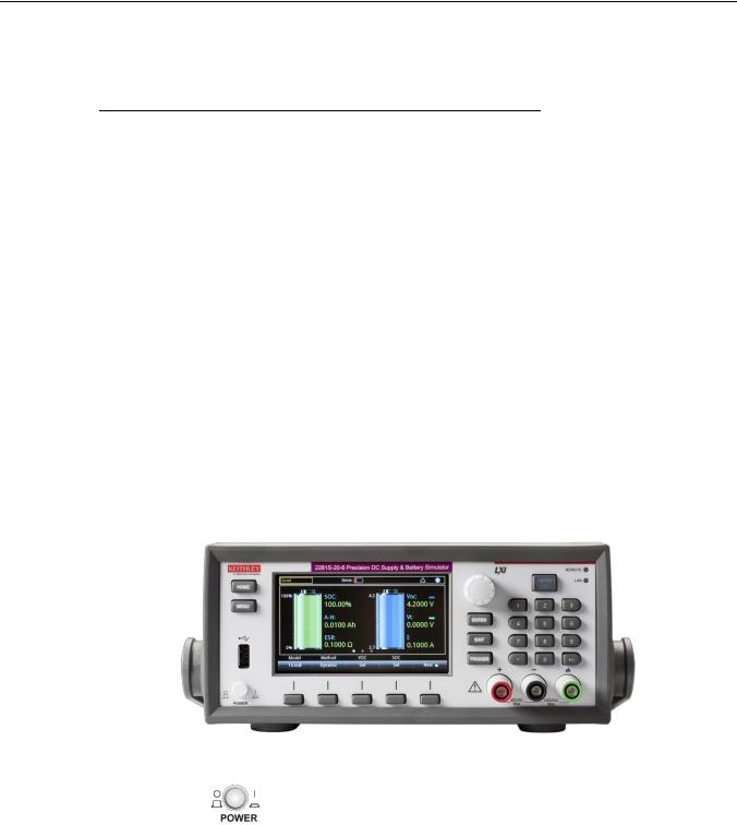
Section 2
General operation
In this section:
Front panel overview ................................................................ |
2-1 |
Rear-panel overview ................................................................ |
2-3 |
Front-panel user interface ........................................................ |
2-4 |
Installing the system............................................................... |
2-37 |
Test connections.................................................................... |
2-49 |
Remote communication interfaces ......................................... |
2-55 |
Set voltage and current limit................................................... |
2-78 |
Select a measurement function.............................................. |
2-80 |
Select a specific measurement range .................................... |
2-82 |
Protection............................................................................... |
2-84 |
Saving setups......................................................................... |
2-88 |
Using the event log ................................................................ |
2-91 |
System information ................................................................ |
2-92 |
Instrument sounds.................................................................. |
2-92 |
Resets.................................................................................... |
2-93 |
Front panel overview
The front panel of 2281S-20-6 is shown below. Descriptions of the controls on the front panel follow the figure.
Figure 1: 2281S-20-6 front panel
POWER switch |
Turns the instrument on or off. To turn the instrument on, press |
|
the power switch so that it is in the on position (|). To turn it off, |
|
press the power switch so that it is in the off position (O). |

Section 2: General operation |
Model 2281S-20-6 Precision DC Supply And Battery Simulator Reference Manual |
HOME key
MENU key
USB port
LCD screen
Navigation control
ENTER key
EXIT key
TRIGGER key
Soft key
OUTPUT ON/OFF switch
Returns the display to the Home screen.
Opens the main menu. Select the icons using the navigation control and pressing the ENTER key to open source, measure,
views, trigger, and system screens. For details, see Menu overview.
Saves reading buffer data and screen snapshots to a USB flash drive. Also stores and retrieves scripts to and from a USB flash drive. The flash drive must be formatted as a FAT drive.
The 2281S-20-6 has a high-resolution, 4.3-inch color TFT LCD display. You can access additional interactive screens by pressing the front-panel MENU key.
Turning the navigation control: Moves the cursor to the left or
the right to highlight a listed value or menu item so that you can select it.
Selects the highlighted choice or allows you to edit the selected field.
Returns to the previous screen or closes a dialog box. For example, press the EXIT key when the main menu is displayed to return to the Home screen. When you are viewing a subscreen (for example, the Event Log screen), press the EXIT key to return
to the main menu screen.
Accesses trigger-related settings and operations. The action of the TRIGGER key depends on the instrument state.
There are five soft keys located under the display. They provide access to additional settings on multiple screens. For example, press first soft key when the main menu screen is displayed to move the cursor to the left.
Turns the output source on or off. The key illuminates when the source output is on.
2-2 |
077114600 / August 2015 |
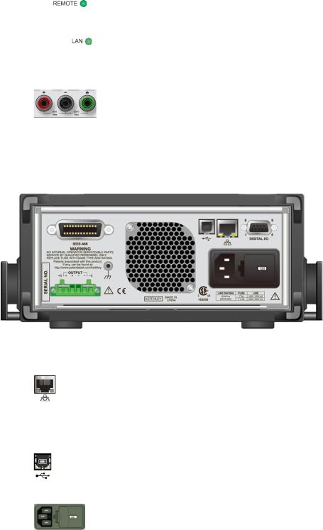
Model 2281S-20-6 Precision DC Supply And Battery Simulator Reference Manual |
Section 2: General operation |
REMOTE LED |
Illuminates when the instrument is controlled through a remote |
indicator |
interface. |
LAN LED indicator |
Illuminates when the instrument is connected to a local area network |
|
(LAN). |
Front panel |
Positive, negative, and ground output binding posts for output |
binding posts |
connections. |
Rear-panel overview
The rear panel of the 2281S-20-6 is shown below; descriptions follow the figure.
Figure 2: 2281S-20-6 rear panel
LAN port
USB port
Power module
Supports full connectivity on a 10 Mbps or 100 Mbps network. The 2281S-20-6 is an LXI version 1.4 Core 2011 compliant instrument that supports TCP/IP and complies with IEEE Std 802.3 (ethernet LAN). See LAN communication (on page 2-59).
USB-B connection for communication, control, and data transfer. For details, see USB communications (on page 2-73).
The power module contains the AC line receptacle, the power line fuse, and the line voltage selector switch. For safety precautions and other details, see Line fuse replacement and Power the instrument on and off (on page 2-46).
077114600 / August 2015 |
2-3 |
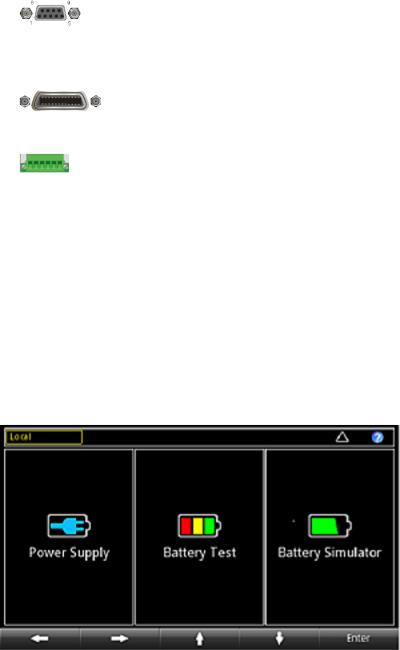
Section 2: General operation |
Model 2281S-20-6 Precision DC Supply And Battery Simulator Reference Manual |
Digital I/O port
IEEE-488 port
Rear output terminals
A digital input/output port that detects and outputs digital signals. he port provides six digital I/O lines. Each output is set high (+5 V) or low (0 V) and can read high or low logic levels. Each digital I/O line is an open-drain signal. Refer to Digital I/O for information.
GPIB connection; the default setting for the 2281S-20-6 is 5. Refer to GPIB setup.
Connections for the source outputs and the sense inputs.
Front-panel user interface
The front-panel user interface gives you quick access to the functions of this instrument. It includes the startup screen to choose function, home screens for three functions, and menus for the functions.
The following topics describe the features of the user interface in more details.
Startup screen
After you turned on the 2281S-20-6, you will see the following startup screen:
Figure 3: Startup screen
2-4 |
077114600 / August 2015 |

Model 2281S-20-6 Precision DC Supply And Battery Simulator Reference Manual |
Section 2: General operation |
As you can see from the figure, 2281S-20-6 has three functions:
High-precision power supply: Supplies 20 V, 6 A DC source
Battery test: Conducts battery charging and discharging test to be able to calculate the capacity and resistance of the battery and create a battery model
Battery simulator: Simulates a battery to determine what the effects the battery has on the Device Under Test (DUT) in different states.
You can choose one function by turning the navigation control or pressing the soft keys and press Enter to access the respective home screens of the function.
Home screens
Each function has its respective home screens.
Home screens for power supply
There are three home screens. The default screen that you see whenever you choose the power supply function is home screen 1. Home screen 2 and home screen 3 give you more settings.
The following figure shows the home screen 1 with the different areas of the screen numbered. Descriptions of the screen areas are in the table following the figure.
Figure 4: Power supply home screen
077114600 / August 2015 |
2-5 |
Loading...