


Model 2000 Multimeter
User’s Manual
A G R E A T E R M E A S U R E O F C O N F I D E N C E

WARRANTY
Keithley Instruments, Inc. warrants this product to be free from defects in material and workmanship for a period of 3 years from date of shipment.
Keithley Instruments, Inc. warrants the following items for 90 days from the date of shipment: probes, cables, rechargeable batteries, diskettes, and documentation.
During the warranty period, we will, at our option, either repair or replace any product that proves to be defective.
To exercise this warranty, write or call your local Keithley representative, or contact Keithley headquarters in Cleveland, Ohio. You will be given prompt assistance and return instructions. Send the product, transportation prepaid, to the indicated service facility. Repairs will be made and the product returned, transportation prepaid. Repaired or replaced products are warranted for the balance of the original warranty period, or at least 90 days.
LIMITATION OF WARRANTY
This warranty does not apply to defects resulting from product modification without Keithley’s express written consent, or misuse of any product or part. This warranty also does not apply to fuses, software, non-rechargeable batteries, damage from battery leakage, or problems arising from normal wear or failure to follow instructions.
THIS WARRANTY IS IN LIEU OF ALL OTHER WARRANTIES, EXPRESSED OR IMPLIED, INCLUDING ANY IMPLIED WARRANTY OF MERCHANTABILITY OR FITNESS FOR A PARTICULAR USE. THE REMEDIES PROVIDED HEREIN ARE BUYER’S SOLE AND EXCLUSIVE REMEDIES.
NEITHER KEITHLEY INSTRUMENTS, INC. NOR ANY OF ITS EMPLOYEES SHALL BE LIABLE FOR ANY DIRECT, INDIRECT, SPECIAL, INCIDENTAL OR CONSEQUENTIAL DAMAGES ARISING OUT OF THE USE OF ITS INSTRUMENTS AND SOFTWARE EVEN IF KEITHLEY INSTRUMENTS, INC., HAS BEEN ADVISED IN ADVANCE OF THE POSSIBILITY OF SUCH DAMAGES. SUCH EXCLUDED DAMAGES SHALL INCLUDE, BUT ARE NOT LIMITED TO: COSTS OF REMOVAL AND INSTALLATION, LOSSES SUSTAINED AS THE RESULT OF INJURY TO ANY PERSON, OR DAMAGE TO PROPERTY.
|
|
|
Keithley Instruments, Inc. |
28775 Aurora Road • Cleveland, Ohio 44139 • 440-248-0400 • Fax: 440-248-6168 |
|
|
|
1-888-KEITHLEY (534-8453) • www.keithley.com |
Sales Offices: BELGIUM: |
Bergensesteenweg 709 • B-1600 Sint-Pieters-Leeuw • 02-363 00 40 • Fax: 02/363 00 64 |
|
CHINA: |
Yuan Chen Xin Building, Room 705 • 12Yumin Road, Dewai, Madian • Beijing 100029 • 8610-6202-2886 • Fax: 8610-6202-2892 |
|
FINLAND: |
Tietäjäntie 2 • 02130 Espoo • Phone: 09-54 75 08 10 • Fax: 09-25 10 51 00 |
|
FRANCE: |
3, allée des Garays • 91127 Palaiseau Cédex • 01-64 53 20 20 • Fax: 01-60 11 77 26 |
|
GERMANY: |
Landsberger Strasse 65 • 82110 Germering • 089/84 93 07-40 • Fax: 089/84 93 07-34 |
|
GREAT BRITAIN: |
Unit 2 Commerce Park, Brunel Road • Theale • Berkshire RG7 4AB • 0118 929 7500 • Fax: 0118 929 7519 |
|
INDIA: |
Flat 2B, Willocrissa • 14, Rest House Crescent • Bangalore 560 001 • 91-80-509-1320/21 • Fax: 91-80-509-1322 |
|
ITALY: |
Viale San Gimignano, 38 • 20146 Milano • 02-48 39 16 01 • Fax: 02-48 30 22 74 |
|
KOREA: |
FL., URI Building • 2-14 Yangjae-Dong • Seocho-Gu, Seoul 137-130 • 82-2-574-7778 • Fax: 82-2-574-7838 |
|
NETHERLANDS: |
Postbus 559 • 4200 AN Gorinchem • 0183-635333 • Fax: 0183-630821 |
|
SWEDEN: |
c/o Regus Business Centre • Frosundaviks Allé 15, 4tr • 169 70 Solna • 08-509 04 679 • Fax: 08-655 26 10 |
|
SWITZERLAND: |
Kriesbachstrasse 4 • 8600 Dübendorf • 01-821 94 44 • Fax: 01-820 30 81 |
|
TAIWAN: |
1FL., 85 Po Ai Street • Hsinchu, Taiwan, R.O.C. • 886-3-572-9077• Fax: 886-3-572-9031 |
|
|
|
© Copyright 2001 Keithley Instruments, Inc. |
|
|
Printed in the U.S.A. |
11/01

Model 2000 Multimeter
User’s Manual
©1994, Keithley Instruments, Inc.
All rights reserved.
Cleveland, Ohio, U.S.A.
Seventh Printing, December 2001
Document Number: 2000-900-01 Rev. G

Manual Print History
The print history shown below lists the printing dates of all Revisions and Addenda created for this manual. The Revision Level letter increases alphabetically as the manual undergoes subsequent updates. Addenda, which are released between Revisions, contain important change information that the user should incorporate immediately into the manual. Addenda are numbered sequentially. When a new Revision is created, all Addenda associated with the previous Revision of the manual are incorporated into the new Revision of the manual. Each new Revision includes a revised copy of this print history page.
Revision A (Document Number 2000-900-01).............................................................. |
November 1994 |
Revision B (Document Number 2000-900-01)................................................................ |
February 1995 |
Revision C (Document Number 2000-900-01).................................................................... |
March 1995 |
Addendum C (Document Number 2000-900-02) .................................................................. |
April 1995 |
Revision D (Document Number 2000-900-01)................................................................... |
August 1995 |
Addendum D (Document Number 2000-900-02) .............................................................. |
October 1995 |
Addendum D (Document Number 2000-900-03) .......................................................... |
September 1996 |
Revision E (Document Number 2000-900-01) .................................................................... |
March 1997 |
Revision F (Document Number 2000-900-01) ...................................................................... |
April 1999 |
Revision G (Document Number 2000-900-01).............................................................. |
December 2001 |
All Keithley product names are trademarks or registered trademarks of Keithley Instruments, Inc. Other brand names are trademarks or registered trademarks of their respective holders.

Safety Precautions
The following safety precautions should be observed before using this product and any associated instrumentation. Although some instruments and accessories would normally be used with non-hazardous voltages, there are situations where hazardous conditions may be present.
This product is intended for use by qualified personnel who recognize shock hazards and are familiar with the safety precautions required to avoid possible injury. Read and follow all installation, operation, and maintenance information carefully before using the product. Refer to the manual for complete product specifications.
If the product is used in a manner not specified, the protection provided by the product may be impaired.
The types of product users are:
Responsible body is the individual or group responsible for the use and maintenance of equipment, for ensuring that the equipment is operated within its specifications and operating limits, and for ensuring that operators are adequately trained.
Operators use the product for its intended function. They must be trained in electrical safety procedures and proper use of the instrument. They must be protected from electric shock and contact with hazardous live circuits.
Maintenance personnel perform routine procedures on the product to keep it operating properly, for example, setting the line voltage or replacing consumable materials. Maintenance procedures are described in the manual. The procedures explicitly state if the operator may perform them. Otherwise, they should be performed only by service personnel.
Service personnel are trained to work on live circuits, and perform safe installations and repairs of products. Only properly trained service personnel may perform installation and service procedures.
Keithley products are designed for use with electrical signals that are rated Installation Category I and Installation Category II, as described in the International Electrotechnical Commission (IEC) Standard IEC 60664. Most measurement, control, and data I/O signals are Installation Category I and must not be directly connected to mains voltage or to voltage sources with high transient over-voltages. Installation Category II connections require protection for high transient over-voltages often associated with local AC mains connections. Assume all measurement, control, and data I/O connections are for connection to Category I sources unless otherwise marked or described in the Manual.
Exercise extreme caution when a shock hazard is present. Lethal voltage may be present on cable connector jacks or test fixtures. The American National Standards Institute (ANSI) states that a shock hazard exists when voltage levels greater than 30V RMS, 42.4V peak, or 60VDC are present. A good safety practice is to expect that hazardous voltage is present in any unknown circuit before measuring.
Operators of this product must be protected from electric shock at all times. The responsible body must ensure that operators are prevented access and/or insulated from every connection point. In some cases, connections must be exposed to potential human contact. Product operators in these circumstances must be trained to protect themselves from the risk of electric shock. If the circuit is capable of operating at or above 1000 volts, no conductive part of the circuit may be exposed.
Do not connect switching cards directly to unlimited power circuits. They are intended to be used with impedance limited sources. NEVER connect switching cards directly to AC mains. When connecting sources to switching cards, install protective devices to limit fault current and voltage to the card.
Before operating an instrument, make sure the line cord is connected to a properly grounded power receptacle. Inspect the connecting cables, test leads, and jumpers for possible wear, cracks, or breaks before each use.
When installing equipment where access to the main power cord is restricted, such as rack mounting, a separate main input power disconnect device must be provided, in close proximity to the equipment and within easy reach of the operator.
For maximum safety, do not touch the product, test cables, or any other instruments while power is applied to the circuit under test. ALWAYS remove power from the entire test system and discharge any capacitors before: connecting or disconnecting cables or jumpers, installing or removing switching cards, or making internal changes, such as installing or removing jumpers.

Do not touch any object that could provide a current path to the common side of the circuit under test or power line (earth) ground. Always make measurements with dry hands while standing on a dry, insulated surface capable of withstanding the voltage being measured.
The instrument and accessories must be used in accordance with its specifications and operating instructions or the safety of the equipment may be impaired.
Do not exceed the maximum signal levels of the instruments and accessories, as defined in the specifications and operating information, and as shown on the instrument or test fixture panels, or switching card.
When fuses are used in a product, replace with same type and rating for continued protection against fire hazard.
Chassis connections must only be used as shield connections for measuring circuits, NOT as safety earth ground connections.
If you are using a test fixture, keep the lid closed while power is applied to the device under test. Safe operation requires the use of a lid interlock.
If a  screw is present, connect it to safety earth ground using the wire recommended in the user documentation.
The ! symbol on an instrument indicates that the user should refer to the operating instructions located in the manual.
The  symbol on an instrument shows that it can source or measure 1000 volts or more, including the combined effect of normal and common mode voltages. Use standard safety precautions to avoid personal contact with these voltages.
The WARNING heading in a manual explains dangers that might result in personal injury or death. Always read the associated information very carefully before performing the indicated procedure.
The CAUTION heading in a manual explains hazards that could damage the instrument. Such damage may invalidate the warranty.
Instrumentation and accessories shall not be connected to humans.
Before performing any maintenance, disconnect the line cord and all test cables.
To maintain protection from electric shock and fire, replacement components in mains circuits, including the power transformer, test leads, and input jacks, must be purchased from Keithley Instruments. Standard fuses, with applicable national safety approvals, may be used if the rating and type are the same. Other components that are not safety related may be purchased from other suppliers as long as they are equivalent to the original component. (Note that selected parts should be purchased only through Keithley Instruments to maintain accuracy and functionality of the product.) If you are unsure about the applicability of a replacement component, call a Keithley Instruments office for information.
To clean an instrument, use a damp cloth or mild, water based cleaner. Clean the exterior of the instrument only. Do not apply cleaner directly to the instrument or allow liquids to enter or spill on the instrument. Products that consist of a circuit board with no case or chassis (e.g., data acquisition board for installation into a computer) should never require cleaning if handled according to instructions. If the board becomes contaminated and operation is affected, the board should be returned to the factory for proper cleaning/servicing.
11/01

Table of Contents
1 General Information
Introduction.......................................................................................... |
1-2 |
Feature overview.................................................................................. |
1-2 |
Warranty information........................................................................... |
1-3 |
Manual addenda................................................................................... |
1-3 |
Safety symbols and terms .................................................................... |
1-3 |
Specifications ....................................................................................... |
1-3 |
Inspections ........................................................................................... |
1-4 |
Options and accessories ....................................................................... |
1-5 |
2 Basic Measurements
Introduction.......................................................................................... |
2-2 |
Front panel summary ........................................................................... |
2-3 |
Rear panel summary ............................................................................ |
2-6 |
Power-up .............................................................................................. |
2-8 |
Display ............................................................................................... |
2-17 |
Measuring voltage.............................................................................. |
2-18 |
Measuring current .............................................................................. |
2-22 |
Measuring resistance ......................................................................... |
2-24 |
Measuring frequency and period ....................................................... |
2-26 |
Measuring temperature ...................................................................... |
2-28 |
Math ................................................................................................... |
2-30 |
Measuring continuity ......................................................................... |
2-34 |
Testing diodes .................................................................................... |
2-35 |
3 Measurement Options
Introduction.......................................................................................... |
3-2 |
Measurement configuration ................................................................. |
3-3 |
Trigger operations................................................................................ |
3-8 |
Buffer operations ............................................................................... |
3-17 |
Limit operations................................................................................. |
3-20 |
Scan operations .................................................................................. |
3-22 |
System operations .............................................................................. |
3-32 |
4 Remote Operation
Introduction.......................................................................................... |
4-2 |
Selecting a language ............................................................................ |
4-4 |
RS-232 operation ................................................................................. |
4-6 |
GPIB bus operation and reference ....................................................... |
4-9 |
Status structure................................................................................... |
4-19 |

Trigger model (GPIB operation) ....................................................... |
4-29 |
Programming syntax ......................................................................... |
4-32 |
Common commands.......................................................................... |
4-39 |
5 SCPI Command Reference
SCPI Signal oriented measurement commands |
.................................. 5-3 |
SCPI command subsystems reference tables ...................................... |
5-7 |
Calculate subsystem .......................................................................... |
5-20 |
DISPlay subsystem............................................................................ |
5-26 |
:FORMat subsystem .......................................................................... |
5-28 |
ROUTe subsystem ............................................................................. |
5-32 |
[SENSe[1]] subsystem ...................................................................... |
5-37 |
STATus subsystem............................................................................. |
5-52 |
:SYSTem subsystem.......................................................................... |
5-61 |
:TRACe subsystem............................................................................ |
5-68 |
Trigger subsystem ............................................................................. |
5-70 |
:UNIT subsystem............................................................................... |
5-74 |
A Specifications
Accuracy calculations......................................................................... |
A-7 |
Optimizing measurement accuracy .................................................. |
A-10 |
Optimizing measurement speed ....................................................... |
A-11 |
BStatus and Error Messages
CExample Programs
Program examples .............................................................................. |
C-2 |
DModels 196/199 and 8840A/8842A Commands
EIEEE-488 Bus Overview
Introduction ......................................................................................... |
E-2 |
Bus description .................................................................................... |
E-4 |
Bus lines .............................................................................................. |
E-6 |
Bus commands .................................................................................... |
E-8 |
Interface function codes .................................................................... |
E-15 |
F IEEE-488 and SCPI Conformance Information
Introduction ......................................................................................... |
F-2 |

List of Illustrations
2 Basic Measurements
Model 2000 front panel ....................................................................... |
2-3 |
Model 2000 rear panel ......................................................................... |
2-6 |
Power module ...................................................................................... |
2-8 |
DC and AC voltage measurements .................................................... |
2-19 |
DC and AC current measurements..................................................... |
2-22 |
Twoand four-wire resistance measurements.................................... |
2-25 |
Frequency and period measurements................................................. |
2-27 |
Thermocouple temperature measurements ........................................ |
2-28 |
Continuity measurements .................................................................. |
2-34 |
Diode testing ...................................................................................... |
2-35 |
3 Measurement Options
Moving average and repeating filters................................................... |
3-4 |
Front panel triggering without stepping/scanning ............................... |
3-8 |
Rear panel pinout ............................................................................... |
3-11 |
Trigger link input pulse specifications (EXT TRIG) ......................... |
3-12 |
Trigger link output pulse specifications (VMC) ................................ |
3-12 |
DUT test system ................................................................................ |
3-13 |
Trigger link connections .................................................................... |
3-13 |
Operation model for triggering example ........................................... |
3-14 |
DIN to BNC trigger cable.................................................................. |
3-16 |
Buffer locations.................................................................................. |
3-18 |
Using limit test to sort 100Ω , 10% resistors...................................... |
3-21 |
Front panel triggering with stepping.................................................. |
3-24 |
Front panel triggering with scanning ................................................. |
3-25 |
Internal scanning example with reading count option ....................... |
3-27 |
Internal scanning example with timer and delay options .................. |
3-29 |
External scanning example with Model 7001 ................................... |
3-31 |
4 Remote Operation
RS-232 interface connector ................................................................. |
4-8 |
IEEE-488 connector........................................................................... |
4-10 |
IEEE-488 connections ....................................................................... |
4-10 |
IEEE-488 connector location............................................................. |
4-11 |
Model 2000 status register structure.................................................. |
4-19 |
Standard event status ......................................................................... |
4-22 |
Operation event status........................................................................ |
4-22 |
Measurement event status .................................................................. |
4-23 |
Questionable event status................................................................... |
4-23 |
Status byte and Service Request (SRQ)............................................. |
4-25 |
Trigger model (GPIB operation)........................................................ |
4-29 |

Device action (trigger model)............................................................ |
4-31 |
Standard event enable register........................................................... |
4-41 |
Standard event status register ............................................................ |
4-43 |
Service request enable register .......................................................... |
4-49 |
Status byte register ............................................................................ |
4-51 |
5 SCPI Command Reference
ASCII data format ............................................................................. |
5-28 |
IEEE754 single precision data format (32 data bits)......................... |
5-29 |
IEEE754 double precision data format (64 data bits) ....................... |
5-29 |
Measurement event register............................................................... |
5-53 |
Questionable event register ............................................................... |
5-54 |
Operation event register .................................................................... |
5-55 |
Measurement event enable register ................................................... |
5-57 |
Questionable event enable register .................................................... |
5-57 |
Operation event enable register ......................................................... |
5-57 |
Key-press codes................................................................................. |
5-66 |
E IEEE-488 Bus Overview
IEEE-488 bus configuration ................................................................ |
E-5 |
IEEE-488 handshake sequence ........................................................... |
E-7 |
Command codes ................................................................................ |
E-12 |
List of Tables
2 Basic Measurements
Fuse ratings .......................................................................................... |
2-9 |
Factory defaults.................................................................................. |
2-13 |
Crest factor limitations ...................................................................... |
2-18 |
3 Measurement Options
Rate settings for the measurement functions ....................................... |
3-7 |
Auto delay settings .............................................................................. |
3-9 |
Bus commands parameters for stepping and scanning counters ....... |
3-28 |
4 Remote Operation
Language supported............................................................................. |
4-4 |
RS-232 connector pinout ..................................................................... |
4-8 |
General bus commands and associated statements............................ |
4-14 |
IEEE-488.2 common commands and queries.................................... |
4-39 |
5 SCPI Command Reference
Signal oriented measurement command summary |
..............................5-3 |
CALCulate command summary .......................................................... |
5-8 |
DISPlay command summary ............................................................... |
5-9 |
FORMat command summary .............................................................. |
5-9 |
ROUTe command summary .............................................................. |
5-10 |
SENSe command summary ............................................................... |
5-10 |
STATus command summary .............................................................. |
5-16 |
SYSTem command summary ............................................................ |
5-17 |
TRACe command summary .............................................................. |
5-17 |
Trigger command summary............................................................... |
5-18 |
UNIT command summary ................................................................. |
5-19 |
B Status and Error Messages
Status and error messages ................................................................... |
B-2 |
D Models 196/199 and 8840A/8842A Commands
Models 196/199 device-dependent command summary .................... |
D-2 |
Models 8840A/8842A device-dependent command |
|
Summary .......................................................................................... |
D-6 |

E IEEE-488 Bus Overview
IEEE-488 bus command summary ..................................................... |
E-8 |
Hexadecimal and decimal command codes ...................................... |
E-11 |
Typical addressed command sequence ............................................. |
E-13 |
Typical addressed command sequence ............................................. |
E-13 |
IEEE command groups ..................................................................... |
E-14 |
Model 2000 interface function codes ............................................... |
E-15 |
F IEEE-488 and SCPI Conformance Information
IEEE-488 documentation requirements.............................................. |
F-2 |
Coupled commands ............................................................................ |
F-4 |

1
General
Information

1-2 General Information
Introduction
This section contains general information about the Model 2000 Multimeter. The information is organized as follows:
•Feature overview
•Warranty information
•Manual addenda
•Safety symbols and terms
•Specifications
•Inspection
•Options and accessories
If you have any questions after reviewing this information, please contact your local Keithley representative or call one of our Applications Engineers at 1-800-348-3735 (U.S. and Canada only). Worldwide phone numbers are listed at the front of this manual.
Feature overview
The Model 2000 is a 6½-digit high-performance digital multimeter. It has 0.002% 90-day basic DC voltage accuracy and 0.008% 90-day basic resistance accuracy. At 6½ digits, the multimeter delivers 50 triggered readings/sec over the IEEE-488 bus. At 4½ digits, it can read up to 2000 readings/sec into its internal buffer. The Model 2000 has broad measurement ranges:
•DC voltage from 0.1µ V to 1000V.
•AC (RMS) voltage from 0.1µ V to 750V, 1000V peak.
•DC current from 10nA to 3A.
•AC (RMS) current from 1µ A to 3A.
• Two and four-wire resistance from 100µ Ω to 120MΩ .
•Frequency from 3Hz to 500kHz.
•Thermocouple temperature from -200°C to +1372°C.
Some additional capabilities of the Model 2000 include:
•Full range of functions — In addition to those listed above, the Model 2000 functions include period, dB, dBm, continuity, diode testing, mX+b, and percent.
•Optional scanning — For internal scanning, options include the Model 2000-SCAN, a 10-channel, general-purpose card, and the Model 2001-TCSCAN, a 9-channel, thermocouple card with a built-in cold junction. For external scanning, the Model 2000 is compatible with Keithley's Model 7001 and 7002 switch matrices and cards.
•Programming languages and remote interfaces — The Model 2000 offers three programming language choices (SCPI, Keithley Models 196/199, and Fluke 8840A/8842A) and two remote interface ports (IEEE-488/GPIB and RS-232C).
•Reading and setup storage — Up to 1024 readings and two setups (user and factory defaults) can be stored and recalled.
•Closed-cover calibration — The instrument can be calibrated either from the front panel or remote interface.

General Information |
1-3 |
|
|
Warranty information
Warranty information is located at the front of this instruction manual. Should your Model 2000 require warranty service, contact the Keithley representative or authorized repair facility in your area for further information. When returning the instrument for repair, be sure to fill out and include the service form at the back of this manual to provide the repair facility with the necessary information.
Manual addenda
Any improvements or changes concerning the instrument or manual will be explained in an addendum included with the manual. Be sure to note these changes and incorporate them into the manual.
Safety symbols and terms
The following symbols and terms may be found on the instrument or used in this manual.
The ! symbol on the instrument indicates that the user should refer to the operating instructions located in the manual.
The  symbol on the instrument shows that high voltage may be present on the terminal(s). Use standard safety precautions to avoid personal contact with these voltages.
The WARNING heading used in this manual explains dangers that might result in personal injury or death. Always read the associated information very carefully before performing the indicated procedure.
The CAUTION heading used in this manual explains hazards that could damage the instrument. Such damage may invalidate the warranty.
Specifications
Full Model 2000 specifications are included in Appendix A.

1-4 General Information
Inspection
The Model 2000 was carefully inspected electrically and mechanically before shipment. After unpacking all items from the shipping carton, check for any obvious signs of physical damage that may have occurred during transit. (Note: There may be a protective film over the display lens, which can be removed.) Report any damage to the shipping agent immediately. Save the original packing carton for possible future reshipment. The following items are included with every Model 2000 order:
•Model 2000 Multimeter with line cord.
•Safety test leads (Model 1751).
•Accessories as ordered.
•Certificate of calibration.
•Model 2000 User's Manual (P/N 2000-900-00).
•Model 2000 Calibration Manual (P/N 2000-905-00).
•Model 2000 Support Software Disk including TestPoint run-time applications, TestPoint instrument libraries for GPIB and RS-232, and QuickBASIC examples.
If an additional manual is required, order the appropriate manual package. The manual packages include a manual and any pertinent addenda.
General Information |
1-5 |
|
|
Options and accessories
The following options and accessories are available from Keithley for use with the Model 2000.
Scanner cards
Model 2000-SCAN: This is a 10-channel scanner card that installs in the option slot of the Model 2000. Channels can be configured for 2-pole or 4-pole operation. Included are two pairs of leads for connection to Model 2000 rear panel inputs (Keithley P/N CA-109).
Model 2001-TCSCAN: This is a thermocouple scanner card that installs in the option slot of the Model 2000. The card has nine analog input channels that can be used for high-accuracy, high-speed scanning. A built-in temperature reference allows multi-channel, cold-junction compensated temperature measurements using thermocouples.
General purpose probes
Model 1754 Universal Test Lead Kit: Consists of one set of test leads (0.9m), two spade lugs, two banana plugs, two hooks, and two alligator clips.
Model 8605 High Performance Modular Test Leads: Consists of two high voltage (1000V) test probes and leads. The test leads are terminated with a banana plug with retractable sheath on each end.
Model 8606 High Performance Probe Tip Kit: Consists of two spade lugs, two alligator clips, and two spring hook test probes. (The spade lugs and alligator clips are rated at 30V RMS, 42.4V peak; the test probes are rated at 1000V.) These components are for use with high performance test leads terminated with banana plugs, such as the Model 8605.
The following test leads and probes are rated at 30V RMS, 42.4V peak:
Models 5805 and 5805-12 Kelvin Probes: Consists of two spring-loaded Kelvin test probes with banana plug termination. Designed for instruments that measure 4-terminal resistance. The Model 5805 is 0.9m long; the Model 5805-12 is 3.6m long.
Model 5806 Kelvin Clip Lead Set: Includes two Kelvin clip test leads (0.9m) with banana plug termination. Designed for instruments that measure 4-terminal resistance. A set of eight replacement rubber bands is available as Keithley P/N GA-22.
Model 8604 SMD Probe Set: Consists of two test leads (0.9m), each terminated with a surface mount device “grabber” clip on one end and a banana plug with a retractable sheath on the other end.

1-6 General Information
Low thermal probes
Model 8610 Low Thermal Shorting Plug: Consists of four banana plugs mounted to a 1- inch square circuit board, interconnected to provide a short circuit among all plugs.
Model 8611 Low Thermal Patch Leads: Consists of two test leads (0.9m), each with a banana plug with a retractable sheath at each end. These leads minimize the thermally-induced offsets that can be created by test leads.
Model 8612 Low Thermal Spade Leads: Consists of two test leads (0.9m), each terminated with a spade lug on one end and a banana plug with a retractable sheath on the other end. These leads minimize the thermally-induced offsets that can be created by test leads.
Cables and adapters
Models 7007-1 and 7007-2 Shielded GPIB Cables: Connect the Model 2000 to the GPIB bus using shielded cables and connectors to reduce electromagnetic interference (EMI). The Model 7007-1 is 1m long; the Model 7007-2 is 2m long.
Models 8501-1 and 8501-2 Trigger Link Cables: Connect the Model 2000 to other instruments with Trigger Link connectors (e.g., Model 7001 Switch System). The Model 8501-1 is 1m long; the Model 8501-2 is 2m long.
Model 8502 Trigger Link Adapter: Allows you to connect any of the six Trigger Link lines of the Model 2000 to instruments that use the standard BNC trigger connectors.
Model 8504 DIN to BNC Trigger Cable: Allows you to connect Trigger Link lines one (Voltmeter Complete) and two (External Trigger) of the Model 2000 to instruments that use BNC trigger connectors. The Model 8504 is 1m long.
Rack mount kits
Model 4288-1 Single Fixed Rack Mount Kit: Mounts a single Model 2000 in a standard 19inch rack.
Model 4288-2 Side-by-Side Rack Mount Kit: Mounts two instruments (Models 182, 428, 486, 487, 2000, 2001, 2002, 6517, 7001) side-by-side in a standard 19-inch rack.
Model 4288-3 Side-by-Side Rack Mount Kit: Mounts a Model 2000 and a Model 199 side- by-side in a standard 19-inch rack.
Model 4288-4 Side-by-Side Rack Mount Kit: Mounts a Model 2000 and a 5.25-inch instrument (Models 195A, 196, 220, 224, 230, 263, 595, 614, 617, 705, 740, 775, etc.) side-by-side in a standard 19-inch rack.
Carrying case
Model 1050 Padded Carrying Case:A carrying case for a Model 2000. Includes handles and shoulder strap.

2
Basic
Measurements

2-2 Basic Measurements
Introduction
This section summarizes front panel operation of the Model 2000. It is organized as follows:
•Front panel summary — Includes an illustration and summarizes keys, display, and connections.
•Rear panel summary — Includes an illustration and summarizes connections.
•Power-up — Describes connecting the instrument to line power, the power-up sequence, the warm-up time, and default conditions.
•Display — Discusses the display format and messages that may appear while using the instrument.
•Measuring voltage — Covers DC and AC voltage measurement connections and low level voltage considerations.
•Measuring current — Covers DC and AC current measurement connections and current fuse replacement.
•Measuring resistance — Details two and four-wire measurement connections and shielding considerations.
•Measuring frequency and period — Covers frequency and period measurement connections.
•Measuring temperature — Describes the use of thermocouples for temperature measurements.
•Math — Covers the mX+b, percent, dBm, and dB math functions performed on single readings.
•Measuring continuity — Explains setting up and measuring continuity of a circuit.
•Testing diodes — Describes testing general-purpose and zener diodes.
Basic Measurements |
2-3 |
|
|
Front panel summary
The front panel of the Model 2000 is shown in Figure 2-1. This figure includes important abbreviated information that should be reviewed before operating the instrument.
Figure 2-1
Model 2000 front panel
|
REM |
STEP SCAN |
CH1 |
CH2 |
CH3 |
CH4 |
CH5 |
CH6 |
CH7 |
CH8 CH9 |
CH10 MATH |
5 |
TALK |
|
|
|
|
|
|
|
|
|
REAR |
LSTN |
|
|
|
|
|
|
|
|
|
|
|
SRQ |
|
|
|
|
|
|
|
|
|
|
|
SHIFT |
|
|
|
|
|
|
|
|
|
4W |
|
|
TIMER |
HOLD TRIG |
FAST |
MED |
SLOW |
REL |
FILT |
AUTO |
ERR |
BUFFER |
STAT |
2000 MULTIMETER
1 |
|
MX+B |
% |
dBm |
dB |
CONT |
|
PERIOD |
TCOUPL |
SHIFT |
DCV |
ACV |
DCI |
ACI |
Ω 2 |
Ω 4 |
FREQ |
TEMP |
|
3 |
|
|
|
|
|
|
|
|
RANGE |
LOCAL |
DELAY |
HOLD |
LIMITS |
ON/OFF |
TEST |
CAL |
|
AUTO |
|
EX TRIG |
TRIG |
STORE RECALL |
FILTER |
REL |
|
||||
|
|
|
|
||||||
|
POWER |
SAVE |
SETUP |
CONFIG |
HALT |
GPIB |
RS232 |
|
RANGE |
OPEN |
CLOSE |
STEP |
SCAN |
DIGITS RATE |
EXIT |
ENTER |
SENSE |
|
INPUT |
6 |
Ω 4 WIRE |
|
||
HI |
|
||
|
|
|
|
350V |
! |
|
1000V |
PEAK |
|
PEAK |
|
|
|
||
|
LO |
|
500V |
|
|
|
|
INPUTS |
|
|
PEAK |
|
|
|
F  R
R
FRONT/REAR |
3A 250V
AMPS
|
|
|
|
|
|
|
|
4 |
|
|
|
|
|
|
|
|
|
|
|
|
|
|
|
|
|
|
|
|
|
|
|
|
|
|
|
|
|
|
|
|
|
|
|
|
|
|
|
|
|
|
|
|
|
|
|
|
|
|
|
|
|
|
|
|
2 |
8 |
7 |
|
|
|
|||||||
1Function keys (shifted and unshifted)
Select measurement function (DC and AC voltage, DC and AC current, 2-wire and 4-wire resistance, frequency, period, temperature with thermocouples), math function (mX+b, %, dBm, dB), or special function (continuity, diode test).
2Operation keys
EXTRIG |
Selects external triggers (front panel, bus, trigger link) as the trigger source. |
||
TRIG |
Triggers a measurement from the front panel. |
|
|
STORE |
Enables reading storage. |
|
|
RECALL |
Displays stored readings and buffer statistics (maximum, minimum, average, |
||
|
standard deviation). Use ▲ and ▼ to scroll through buffer; use |
and |
to |
|
toggle between reading number and reading. |
|
|
FILTER |
Displays digital filter status for present function and toggles filter on/off. |
|
|
REL |
Enables/disables relative reading on present function. |
|
|
and |
Moves through selections within functions and operations. If scanner card in- |
||
|
stalled, manually scans channels. |
|
|
OPEN |
Opens all channels on internal scanner card; stops scanning. |
|
|
CLOSE |
Closes selected internal channel. |
|
|
STEP |
Steps through channels; sends a trigger after each channel. |
|
|
SCAN |
Scans through channels; sends a trigger after last channel. |
|
|
DIGITS |
Changes number of digits of resolution. |
|
|
RATE |
Changes reading rate: fast, medium, slow. |
|
|
EXIT |
Cancels selection, moves back to measurement display. |
|
|
ENTER |
Accepts selection, moves to next choice or back to measurement display. |
|
|
SHIFT |
Used to access shifted keys. |
|
|
LOCAL |
Cancels GPIB remote mode. |
|
|

2-4 Basic Measurements
3 Shifted operation keys
DELAY |
Sets user delay between trigger and measurement. |
HOLD |
Holds reading when the selected number of samples is within the selected tol- |
|
erance. |
LIMITS |
Sets upper and lower limit values for readings. |
ON/OFF |
Enables/disables limits; selects beeper operation for limit testing. |
TEST |
Selects built-in tests, diagnostics, display test. |
CAL |
Accesses calibration. |
SAVE |
Saves present configuration for power-on user default. |
SETUP |
Restores factory or user default configuration. |
CONFIG |
Selects minimum/maximum channels, timer, and reading count for step/scan. |
HALT |
Turns off step/scan. |
GPIB |
Enables/disables GPIB interface; selects address and language. |
RS232 |
Enables/disables RS-232 interface; selects baud rate, flow control, terminator. |
4 Range keys
▲Moves to higher range; increments digit; moves to next selection.
▼Moves to lower range; decrements digit; moves to previous selection.
|
|
|
|
AUTO |
Enables/disables autorange. |
|
5 Annunciators |
||||||
|
|
|
|
*(asterisk) |
Reading being stored. |
|
|
|
|
|
(diode) |
Instrument is in diode testing function. |
|
|
))) |
(speaker) |
Beeper on for continuity or limits testing. |
|||
|
|
|
|
|
(more) |
Indicates additional selections are available. |
|
|
|
|
|
||
|
|
|
|
4W |
4-wire resistance reading displayed. |
|
|
|
|
|
AUTO |
Autoranging enabled. |
|
|
|
|
|
BUFFER |
Recalling stored readings. |
|
|
|
|
|
CH 1-10 |
Displayed internal channel is closed. |
|
|
|
|
|
ERR |
Questionable reading; invalid cal step. |
|
|
|
|
|
FAST |
Fast reading rate. |
|
|
|
|
|
FILT |
Digital filter enabled. |
|
|
|
|
|
HOLD |
Instrument is in hold mode. |
|
|
|
|
|
LSTN |
Instrument addressed to listen over GPIB. |
|
|
|
|
|
MATH |
Math function (mX+b, %, dB, dBm) enabled. |
|
|
|
|
|
MED |
Medium reading rate. |
|
|
|
|
|
REAR |
Reading acquired from rear inputs. |
|
|
|
|
|
REL |
Relative reading displayed. |
|
|
|
|
|
REM |
Instrument is in GPIB remote mode. |
|
|
|
|
|
SCAN |
Instrument is in scan mode. |
|
|
|
|
|
SHIFT |
Accessing shifted keys. |
|
|
|
|
|
SLOW |
Slow reading rate. |
|
|
|
|
|
SRQ |
Service request over GPIB. |
|
|
|
|
|
STAT |
Displaying buffer statistics. |
|
|
|
|
|
STEP |
Instrument is in step mode. |
|
|
|
|
|
TALK |
Instrument addressed to talk over GPIB. |
|
|
|
|
|
TIMER |
Timed scans in use. |
|
|
|
|
|
TRIG |
Indicates external trigger (front panel, bus, trigger link) selected. |
|
Basic Measurements |
2-5 |
|
|
6 Input connections
INPUT HI and LO |
Used for making DC volts, AC volts, 2-wire resistance measurements. |
AMPS |
Used in conjunction with INPUT LO to make DC current and AC cur- |
|
rent measurements. Also holds current input fuse (3A, 250V, fast |
SENSE Ω 4 WIRE |
blow, 5× 20mm). |
Used with INPUT HI and LO to make 4-wire resistance measure- |
|
HI and LO |
ments. |
7INPUTS
Selects input connections on front or rear panel.
8Handle
Pull out and rotate to desired position.

2-6 Basic Measurements
Rear panel summary
The rear panel of the Model 2000 is shown in Figure 2-2. This figure includes important abbreviated information that should be reviewed before operating the instrument.
Figure 2-2
Model 2000 rear panel
3 |
4 |
5 |
WARNING:NO INTERNALI OPERATOR SERVICABLEI PARTS,SERVICE, I BY QUALIFIEDI I PERSONNEL ONLY..
HI |
MADE IN |
2 |
|
|
|
U.S.A. |
|
|
|
IEEE-488 |
|
|
|
1000V |
|
(CHANGE IEEE ADDRESS |
350V |
|
TRIGGER |
FROM FRONT PANEL) |
|
! |
PEAK |
|
||
PEAK |
LINK |
|
||
|
RS232 |
|||
|
|
|
|
! |
|
|
|
|
|
LO |
|
500V |
|
|
|
|
|
|
|
|
|
|
|
|
|
|
|
|
|
|
|
|
|
|
|
|
|
|
|
|
SENSE |
|
INPUT PEAK |
1 |
3 |
5 |
VMC |
|
|
|
|
|
|
|
|
|
|
|
|
|
|
|
|
|
|
|
||||
|
|
|
Ω |
4W |
|
|
|
2 |
4 |
6 |
EXT TRIG |
|
|
|
|
|
|
|
|
|
|
|
|
|
|
|
|
|
|
|
||
|
|
|
|
|
|
|
|
|
|
|
|
|
! |
|
|
|
|
|
|
|
|
|
|
|
|
|
|
|
|
|
||
|
|
|
|
|
|
|
|
|
|
|
|
|
|
|
|
|
|
|
|
|
|
|
|
|
|
|
|
|
|
|
|
|
|
|
|
|
|
|
|
|
|
|
|
|
|
|
|
|
|
|
|
|
|
|
|
|
|
|
|
|
|
|
|
|
|
|
|
|
|
|
|
|
|
|
|
|
|
|
|
|
|
|
|
|
|
|
|
|
|
|
|
|
|
|
|
|
|
|
|
|
|
|
|
|
|
|
|
|
|
|
|
FUSE |
|
LINE |
|
|
|
|
|
|
|
|
|
|
|
|
LINE RATING |
6 |
|||
1 |
|
|
|
|
|
|
|
|
|
|
|
|
250mAT |
|
100 VAC |
|
120 |
|
|
50, 60 |
|
|||||||||||
|
! |
|
|
|
|
|
|
|
|
|
|
(SB) |
|
120 VAC |
|
|
|
|
|
|
|
|
|
|
|
|
400HZ |
|||||
|
|
|
|
|
|
|
|
|
|
|
|
|
|
|
|
|
|
|
|
|
|
|
|
|
|
|
|
17 VA MAX |
||||
|
|
|
|
|
|
|
|
|
|
|
|
|
125mAT |
|
220 VAC |
|
|
|
|
|
|
|
|
|
|
|
|
|
|
|
|
|
|
|
|
|
|
|
|
|
|
|
|
|
|
(SB) |
|
240 VAC |
|
|
|
|
|
|
|
|
|
|
|
|
|
|
|
|
|
|
|
|
|
|
|
|
|
|
|
|
|
|
|
|
|
|
|
|
|
|
|
|
|
|
|
|
|
|
|
|
|
|
|
|
|
|
|
|
|
|
|
|
|
|
|
|
|
|
|
|
|
|
|
|
|
|
|
|
|
|
|
|
|||
|
|
|
|
|
|
|
CAUTION:FOR CONTINUEDI |
PROTECTIONI AGAINSTI FIREI HAZARD,REPLACE, |
FUSE WITHI SAME TYPE AND RATINGI .. |
|
|
|
||||||||||||||||||||
|
|
|
|
|
|
|
|
|
|
|
|
|
|
|
|
|
|
|
|
|
|
|
|
|
|
|
|
|
|
|
|
|
|
|
|
|
|
|
|
|
|
|
|
|
|
|
|
|
|
|
|
|
|
|
|
|
|
|
|
|
|
|
|
|
|
|
|
|
|
|
|
|
|
|
|
|
|
|
|
|
|
|
|
|
|
|
|
|
|
|
|
|
|
|
|
|
|
|
|
|
|
|
|
|
|
|
|
|
|
|
|
|
|
|
|
|
|
|
|
|
|
|
|
|
|
|
|
|
|
|
|
|
|
|
|
|
|
|
|
|
|
|
|
|
|
|
|
|
|
|
|
|
|
|
|
|
|
|
|
|
|
|
|
|
|
|
|
|
|
|
|
|
|
|
|
|
|
|
|
|
|
|
|
|
|
|
|
|
|
|
|
|
|
|
|
|
|
|
|
|
|
|
|
|
|
|
|
|
|
|
|
|
|
|
|
|
|
|
|
|
|
|
|
|
|
|
|
|
|
|
8 |
7 |
|
6 |
5 |
|
4 |
3 |
|
2 |
1 |
|
#2 |
#1 |
|
EXTERNAL TRIGGER INPUT |
|
VOLT METER COMPLETE OUTPUT |
Trigger Reading |
|
Reading |
TTL HI |
|
Complete |
|
TTL HI |
|
>72 sec |
|
>10 sec |
TTL LO |
|
TTL LO |
Basic Measurements |
2-7 |
|
|
1Option slot
An optional scanner card (Model 2000-SCAN, 2001-SCAN, or 2001-TCSCAN) installs in this slot.
2Input connections
INPUT HI and LO |
Used for making DC volts, AC volts, 2-wire resistance measurements |
SENSE Ω 4 WIRE |
and for connecting scanner card. |
Used with INPUT HI and LO to make 4-wire resistance measurements |
|
HI and LO |
and also for connecting scanner card. |
3TRIGGER LINK
One 8-pin micro-DIN connector for sending and receiving trigger pulses among other instruments. Use a trigger link cable or adapter, such as Models 8501-1, 8501-2, 8502, 8504.
4RS-232
Connector for RS-232 operation. Use a straight-through (not null modem) DB-9 cable.
5IEEE-488
Connector for IEEE-488 (GPIB) operation. Use a shielded cable, such as Models 7007-1 and 7007-2.
6Power module
Contains the AC line receptacle, power line fuse, and line voltage setting. The Model 2000 can be configured for line voltages of 100V/120V/220V/240VAC at line frequencies of 45Hz to 66Hz or 360Hz to 440Hz.
2-8 Basic Measurements
Power-up
Line power connection
Follow the procedure below to connect the Model 2000 to line power and turn on the instrument.
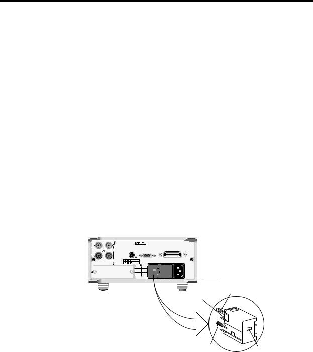
Figure 2-3
Power module
1.Check to see that the line voltage selected on the rear panel (see Figure 2-3) is correct for the operating voltage in your area. If not, refer to the next procedure, “Setting line voltage and replacing fuse.”
CAUTION Operating the instrument on an incorrect line voltage may cause damage to the instrument, possibly voiding the warranty.
2.Before plugging in the power cord, make sure that the front panel power switch is in the off (0) position.
3.Connect the female end of the supplied power cord to the AC receptacle on the rear panel. Connect the other end of the power cord to a grounded AC outlet.
WARNING The power cord supplied with the Model 2000 contains a separate ground wire for use with grounded outlets. When proper connections are made, instrument chassis is connected to power line ground through the ground wire in the power cord. Failure to use a grounded outlet may result in personal injury or death due to electric shock.
4.Turn on the instrument by pressing the front panel power switch to the on (1) position.
Model 2000
WARNING:NO INTERNALI OPERATOR SERVICABLEI PARTS,SERVICE, I BY QUALIFIEDI I PERSONNEL ONLY..
HI |
MADE IN |
|
|
|
|
U.S.A. |
|
|
|
|
IEEE-488 |
|
|
1000V |
|
(CHANGE IEEE ADDRESS |
350V |
|
TRIGGER |
FROM FRONT PANEL) |
|
! |
PEAK |
|
||
PEAK |
|
LINK |
RS232 |
|
|
|
|
|
! |
|
LO |
500V |
1 |
3 |
5 |
VMC |
SENSE |
|
INPUT PEAK |
2 |
4 |
6 |
EXT TRIG |
Ω 4W |
|
|
|
|
! |
|
|
|
FUSE |
LINE |
|
LINE RATING |
|
250mAT |
100 VAC |
120 |
50, 60 |
! |
(SB) |
120 VAC |
|
400HZ |
|
125mAT |
220 VAC |
|
17 VA MAX |
|
(SB) |
240 VAC |
|
|
CAUTION:FOR CONTINUEDI |
PROTECTIONI AGAINSTI FIREI HAZARD,REPLACE, |
FUSE WITHI SAME TYPE AND RATINGI .. |
Line Voltage Selector
Fuse
240 |
|
100 |
120 |
220
Spring
Window
Fuse Holder Assembly
Basic Measurements |
2-9 |
|
|
Setting line voltage and replacing fuse
A rear panel fuse located next to the AC receptacle protects the power line input of the instrument. If the line voltage setting needs to be changed or the line fuse needs to be replaced, perform the following steps.
WARNING Make sure the instrument is disconnected from the AC line and other equipment before changing the line voltage setting or replacing the line fuse.
1.Place the tip of a flat-blade screwdriver into the power module by the fuse holder assembly (see Figure 2-3). Gently push in and to the left. Release pressure on the assembly and its internal spring will push it out of the power module.
2.Remove the fuse and replace it with the type listed in Table 2-1.
CAUTION |
For continued protection against fire or instrument damage, only replace |
|
fuse with the type and rating listed. If the instrument repeatedly blows fuses, |
|
locate and correct the cause of the trouble before replacing the fuse. See the |
|
optional Model 2000 Repair Manual for troubleshooting information. |
3.If configuring the instrument for a different line voltage, remove the line voltage selector from the assembly and rotate it to the proper position. When the selector is installed into the fuse holder assembly, the correct line voltage appears inverted in the window.
4.Install the fuse holder assembly into the power module by pushing it in until it locks in place.
Table 2-1
Fuse ratings
Line voltage |
Fuse rating |
Keithley P/N |
|
|
|
100/120V |
0.25A slow-blow 5× 20mm |
FU-96-4 |
220/240V |
0.125A slow-blow 5× 20mm |
FU-91 |
|
|
|

2-10 Basic Measurements
Power-up sequence
On power-up, the Model 2000 performs self-tests on its EPROM and RAM and momentarily lights all segments and annunciators. If a failure is detected, the instrument momentarily displays an error message and the ERR annunciator turns on. (Error messages are listed in Appendix B.)
NOTE If a problem develops while the instrument is under warranty, return it to Keithley
Instruments, Inc., for repair.
If the instrument passes the self-tests, the firmware revision levels are displayed. An example of this display is:
REV: A01 A02
where: A01 is the main board ROM revision. A02 is the display board ROM revision.
After the power-up sequence, the instrument begins its normal display of readings.
Basic Measurements |
2-11 |
|
|
High energy circuit safety precautions
To optimize safety when measuring voltage in high energy distribution circuits, read and use the directions in the following warning.
WARNING Dangerous arcs of an explosive nature in a high energy circuit can cause severe personal injury or death. If the multimeter is connected to a high energy circuit when set to a current range, low resistance range, or any other low impedance range, the circuit is virtually shorted. Dangerous arcing can result even when the multimeter is set to a voltage range if the minimum voltage spacing is reduced in the external connections.
When making measurements in high energy circuits, use test leads that meet the following requirements:
•Test leads should be fully insulated.
•Only use test leads that can be connected to the circuit (e.g., alligator clips, spade lugs, etc.) for hands-off measurements.
•Do not use test leads that decrease voltage spacing. These diminishes arc protection and create a hazardous condition.
Use the following sequence when testing power circuits:
1.De-energize the circuit using the regular installed connect-disconnect device, such as a circuit breaker, main switch, etc.
2.Attach the test leads to the circuit under test. Use appropriate safety rated test leads for this application.
3.Set the multimeter to the proper function and range.
4.Energize the circuit using the installed connect-disconnect device and make measurements without disconnecting the multimeter.
5.De-energize the circuit using the installed connect-disconnect device.
6.Disconnect the test leads from the circuit under test.
WARNING The maximum common-mode voltage (voltage between INPUT LO and the chassis ground) is 500V peak. Exceeding this value may cause a breakdown in insulation, creating a shock hazard.

2-12 Basic Measurements
Power-on defaults
Power-on defaults are the settings the instrument assumes when it is turned on. The Model 2000 offers two choices for the settings: factory and user. The power-on default will be the last configuration you saved. The SAVE and SETUP keys select the two choices of power-on defaults.
To save present configuration as user settings:
1.Configure the instrument as desired for USER default.
2.Press SHIFT then SAVE.
3.Use the ▲ and ▼ keys to select YES or NO.
4.Press ENTER.
To restore factory or user settings:
1.Press SHIFT then SETUP.
2.Use the ▲ and ▼ keys to select FACTory or USER.
3.Press ENTER.
Since the basic measurement procedures in this manual assume the factory defaults, reset the instrument to the factory settings when following step-by-step procedures. Table 2-2 lists the factory default settings.
 Loading...