


Model 2304A High Speed Power Supply
User’s Manual
A G R E A T E R M E A S U R E O F C O N F I D E N C E

WARRANTY
Keithley Instruments, Inc. warrants this product to be free from defects in material and workmanship for a period of 1 year from date of shipment.
Keithley Instruments, Inc. warrants the following items for 90 days from the date of shipment: probes, cables, rechargeable batteries, diskettes, and documentation.
During the warranty period, we will, at our option, either repair or replace any product that proves to be defective.
To exercise this warranty, write or call your local Keithley representative, or contact Keithley headquarters in Cleveland, Ohio. You will be given prompt assistance and return instructions. Send the product, transportation prepaid, to the indicated service facility. Repairs will be made and the product returned, transportation prepaid. Repaired or replaced products are warranted for the balance of the original warranty period, or at least 90 days.
LIMITATION OF WARRANTY
This warranty does not apply to defects resulting from product modification without Keithley’s express written consent, or misuse of any product or part. This warranty also does not apply to fuses, software, non-rechargeable batteries, damage from battery leakage, or problems arising from normal wear or failure to follow instructions.
THIS WARRANTY IS IN LIEU OF ALL OTHER WARRANTIES, EXPRESSED OR IMPLIED, INCLUDING ANY IMPLIED WARRANTY OF MERCHANTABILITY OR FITNESS FOR A PARTICULAR USE. THE REMEDIES PROVIDED HEREIN ARE BUYER’S SOLE AND EXCLUSIVE REMEDIES.
NEITHER KEITHLEY INSTRUMENTS, INC. NOR ANY OF ITS EMPLOYEES SHALL BE LIABLE FOR ANY DIRECT, INDIRECT, SPECIAL, INCIDENTAL OR CONSEQUENTIAL DAMAGES ARISING OUT OF THE USE OF ITS INSTRUMENTS AND SOFTWARE EVEN IF KEITHLEY INSTRUMENTS, INC., HAS BEEN ADVISED IN ADVANCE OF THE POSSIBILITY OF SUCH DAMAGES. SUCH EXCLUDED DAMAGES SHALL INCLUDE, BUT ARE NOT LIMITED TO: COSTS OF REMOVAL AND INSTALLATION, LOSSES SUSTAINED AS THE RESULT OF INJURY TO ANY PERSON, OR DAMAGE TO PROPERTY.
Keithley Instruments, Inc. • 28775 Aurora Road • Cleveland, OH 44139 • 440-248-0400 • Fax: 440-248-6168 • http://www.keithley.com
CHINA: |
Keithley Instruments China • Yuan Chen Xin Building, Room 705 • 12 Yumin Road, Dewai, Madian • Beijing 100029 • 8610-62022886 • Fax: 8610-62022892 |
FRANCE: |
Keithley Instruments SARL • BP 60 • 3 Allée des Garays • 91122 Palaiseau Cédex • 33-1-60-11-51-55 • Fax: 33-1-60-11-77-26 |
GERMANY: |
Keithley Instruments GmbH • Landsberger Strasse 65 • D-82110 Germering, Munich • 49-89-8493070 • Fax: 49-89-84930759 |
GREAT BRITAIN: |
Keithley Instruments, Ltd. • The Minster • 58 Portman Road • Reading, Berkshire RG30 1EA • 44-118-9575666 • Fax: 44-118-9596469 |
ITALY: |
Keithley Instruments SRL • Viale S. Gimignano 38 • 20146 Milano • 39-2-48303008 • Fax: 39-2-48302274 |
NETHERLANDS: |
Keithley Instruments BV • Avelingen West 49 • 4202 MS Gorinchem • 31-(0)183-635333 • Fax: 31-(0)183-630821 |
SWITZERLAND: |
Keithley Instruments SA • Kriesbachstrasse 4 • 8600 Dübendorf • 41-1-8219444 • Fax: 41-1-8203081 |
TAIWAN: |
Keithley Instruments Taiwan • 1FL., 85 Po Ai Street • Hsinchu, Taiwan • 886-3-572-9077 • Fax: 886-3-572-9031 |
1/99

Model 2304A High Speed Power Supply
User’s Manual
©1998, Keithley Instruments, Inc.
All rights reserved.
Cleveland, Ohio, U.S.A.
Second Printing, March 1999
Document Number: 2304A-900-01 Rev. B

Manual Print History
The print history shown below lists the printing dates of all Revisions and Addenda created for this manual. The Revision Level letter increases alphabetically as the manual undergoes subsequent updates. Addenda, which are released between Revisions, contain important change information that the user should incorporate immediately into the manual. Addenda are numbered sequentially. When a new Revision is created, all Addenda associated with the previous Revision of the manual are incorporated into the new Revision of the manual. Each new Revision includes a revised copy of this print history page.
Revision A (Document Number 2304A-900-01) ......................................................... |
January 1998 |
Revision B (Document Number 2304A-900-01) ........................................................... |
March 1999 |
All Keithley product names are trademarks or registered trademarks of Keithley Instruments, Inc. Other brand names are trademarks or registered trademarks of their respective holders.

Safety Precautions
The following safety precautions should be observed before using this product and any associated instrumentation. Although some instruments and accessories would normally be used with non-hazardous voltages, there are situations where hazardous conditions may be present.
This product is intended for use by qualified personnel who recognize shock hazards and are familiar with the safety precautions required to avoid possible injury. Read the operating information carefully before using the product.
The types of product users are:
Responsible body is the individual or group responsible for the use and maintenance of equipment, for ensuring that the equipment is operated within its specifications and operating limits, and for ensuring that operators are adequately trained.
Operators use the product for its intended function. They must be trained in electrical safety procedures and proper use of the instrument. They must be protected from electric shock and contact with hazardous live circuits.
Maintenance personnel perform routine procedures on the product to keep it operating, for example, setting the line voltage or replacing consumable materials. Maintenance procedures are described in the manual. The procedures explicitly state if the operator may perform them. Otherwise, they should be performed only by service personnel.
Service personnel are trained to work on live circuits, and perform safe installations and repairs of products. Only properly trained service personnel may perform installation and service procedures.
Exercise extreme caution when a shock hazard is present. Lethal voltage may be present on cable connector jacks or test fixtures. The American National Standards Institute (ANSI) states that a shock hazard exists when voltage levels greater than 30V RMS, 42.4V peak, or 60VDC are present. A good safety practice is to expect that hazardous voltage is present in any unknown circuit before measuring.
Users of this product must be protected from electric shock at all times. The responsible body must ensure that users are prevented access and/or insulated from every connection point. In some cases, connections must be exposed to potential human contact. Product users in these circumstances must be trained to protect themselves from the risk of electric shock. If the circuit is capable of operating at or above 1000 volts, no conductive part of the circuit may be exposed.
As described in the International Electrotechnical Commission (IEC) Standard IEC 664, digital multimeter measuring circuits (e.g., Keithley Models 175A, 199, 2000, 2001, 2002, and 2010) are Installation Category II. All other instruments’ signal terminals are Installation Category I and must not be connected to mains.
Do not connect switching cards directly to unlimited power circuits. They are intended to be used with impedance limited sources. NEVER connect switching cards directly to AC mains. When connecting sources to switching cards, install protective devices to limit fault current and voltage to the card.
Before operating an instrument, make sure the line cord is connected to a properly grounded power receptacle. Inspect the connecting cables, test leads, and jumpers for possible wear, cracks, or breaks before each use.
For maximum safety, do not touch the product, test cables, or any other instruments while power is applied to the circuit under test. ALWAYS remove power from the entire test system and discharge any capacitors before: connecting or disconnecting cables or jumpers, installing or removing switching cards, or making internal changes, such as installing or removing jumpers.
Do not touch any object that could provide a current path to the common side of the circuit under test or power line (earth) ground. Always make measurements with dry hands while standing on a dry, insulated surface capable of withstanding the voltage being measured.

The instrument and accessories must be used in accordance with its specifications and operating instructions or the safety of the equipment may be impaired.
Do not exceed the maximum signal levels of the instruments and accessories, as defined in the specifications and operating information, and as shown on the instrument or test fixture panels, or switching card.
When fuses are used in a product, replace with same type and rating for continued protection against fire hazard.
Chassis connections must only be used as shield connections for measuring circuits, NOT as safety earth ground connections.
If you are using a test fixture, keep the lid closed while power is applied to the device under test. Safe operation requires the use of a lid interlock.
If a  screw is present, connect it to safety earth ground using the wire recommended in the user documentation.
The ! symbol on an instrument indicates that the user should refer to the operating instructions located in the manual.
The  symbol on an instrument shows that it can source or measure 1000 volts or more, including the combined effect of normal and common mode voltages. Use standard safety precautions to avoid personal contact with these voltages.
The WARNING heading in a manual explains dangers that might result in personal injury or death. Always read the associated information very carefully before performing the indicated procedure.
The CAUTION heading in a manual explains hazards that could damage the instrument. Such damage may invalidate the warranty.
Instrumentation and accessories shall not be connected to humans.
Before performing any maintenance, disconnect the line cord and all test cables.
To maintain protection from electric shock and fire, replacement components in mains circuits, including the power transformer, test leads, and input jacks, must be purchased from Keithley Instruments. Standard fuses, with applicable national safety approvals, may be used if the rating and type are the same. Other components that are not safety related may be purchased from other suppliers as long as they are equivalent to the original component. (Note that selected parts should be purchased only through Keithley Instruments to maintain accuracy and functionality of the product.) If you are unsure about the applicability of a replacement component, call a Keithley Instruments office for information.
To clean an instrument, use a damp cloth or mild, water based cleaner. Clean the exterior of the instrument only. Do not apply cleaner directly to the instrument or allow liquids to enter or spill on the instrument. Products that consist of a circuit board with no case or chassis (e.g., data acquisition board for installation into a computer) should never require cleaning if handled according to instructions. If the board becomes contaminated and operation is affected, the board should be returned to the factory for proper cleaning/servicing.
Rev. 2/99

Table of Contents
1 |
General Information |
|
|
Introduction ................................................................................ |
1-2 |
|
Warranty information ................................................................. |
1-2 |
|
Manual addenda ......................................................................... |
1-2 |
|
Safety symbols and terms .......................................................... |
1-2 |
|
Specifications ............................................................................. |
1-3 |
|
Inspection ................................................................................... |
1-3 |
2 |
Front Panel Operation |
|
|
Power supply overview .............................................................. |
2-2 |
|
Power-up .................................................................................... |
2-4 |
|
Line power connection ........................................................ |
2-4 |
|
Fuse replacement ................................................................ |
2-5 |
|
Power-up sequence ............................................................. |
2-5 |
|
Default settings ........................................................................... |
2-6 |
|
Display types .............................................................................. |
2-7 |
|
Remote display option ............................................................... |
2-8 |
|
Test connections ......................................................................... |
2-8 |
|
Setting voltage and current values ............................................. |
2-9 |
|
Procedure to edit voltage and current values ...................... |
2-9 |
|
OPERATE ................................................................................ |
2-10 |
|
Output readback ....................................................................... |
2-11 |
|
Current limit ............................................................................. |
2-11 |
|
Enhanced output response ........................................................ |
2-12 |
|
Independent voltage measurements (DVM) ............................. |
2-12 |
|
Pulse-current measurements ..................................................... |
2-12 |
|
Pulse current digitization .................................................. |
2-14 |
|
Programming examples .................................................... |
2-15 |
|
Pulse-current measurement procedure .............................. |
2-16 |
|
Determining correct trigger level ...................................... |
2-16 |
|
Long integration current measurements ................................... |
2-17 |
|
Long integration measurement procedure ........................ |
2-19 |
|
Determining correct trigger level ...................................... |
2-19 |
|
Sink operation .......................................................................... |
2-20 |
|
Relay control ............................................................................ |
2-21 |
|
Connections ....................................................................... |
2-22 |
|
Controlling the relays ........................................................ |
2-23 |
|
MENU ...................................................................................... |
2-24 |
|
Rules to navigate MENU .................................................. |
2-25 |
|
MENU structure ................................................................ |
2-25 |

3 |
GPIB Operation |
|
|
Introduction ................................................................................ |
3-2 |
|
GPIB bus connections ................................................................ |
3-2 |
|
Primary address .......................................................................... |
3-3 |
|
QuickBASIC 4.5 programming .................................................. |
3-3 |
|
Universal language driver installation ................................. |
3-3 |
|
Using program fragments .................................................... |
3-3 |
|
General bus commands ............................................................... |
3-4 |
|
REN (remote enable) ........................................................... |
3-5 |
|
IFC (interface clear) ............................................................ |
3-5 |
|
LLO (local lockout) ............................................................. |
3-5 |
|
GTL (go to local) ................................................................. |
3-6 |
|
DCL (device clear) .............................................................. |
3-6 |
|
SDC (selective device clear) ................................................ |
3-6 |
|
GET (group execute trigger) ............................................... |
3-6 |
|
SPE, SPD (serial polling) .................................................... |
3-7 |
|
Front panel aspects of GPIB operation ....................................... |
3-7 |
|
Remote indicator and LOCAL key ..................................... |
3-7 |
|
Error and status messages ................................................... |
3-7 |
|
Status structure ......................................................................... |
3-11 |
|
Condition registers ............................................................ |
3-12 |
|
Event registers ................................................................... |
3-12 |
|
Enable registers ................................................................. |
3-12 |
|
Queues ............................................................................... |
3-13 |
|
Status Byte and Service Request (SRQ) ........................... |
3-16 |
|
Programming syntax ................................................................. |
3-19 |
|
Command words ............................................................... |
3-19 |
|
Program messages ............................................................. |
3-22 |
|
Response messages ........................................................... |
3-24 |
|
Message exchange protocol ............................................... |
3-24 |
|
Common commands ................................................................. |
3-25 |

4 |
SCPI Command Reference |
|
|
Introduction ................................................................................ |
4-2 |
|
Signal oriented measurement commands ................................... |
4-2 |
|
SCPI command subsystems reference tables ............................. |
4-4 |
|
:DISPlay subsystem ................................................................... |
4-9 |
|
FORMat subsystem .................................................................. |
4-11 |
|
OUTPut subsystem .................................................................. |
4-15 |
|
SENSe subsystem .................................................................... |
4-16 |
|
Voltage, current, and DVM commands ............................. |
4-17 |
|
Current range commands .................................................. |
4-18 |
|
Pulse-current commands ................................................... |
4-19 |
|
:TIMe commands .............................................................. |
4-20 |
|
:SYNChronize commands ................................................ |
4-21 |
|
Long integration commands ..................................................... |
4-22 |
|
SOURce subsystem .................................................................. |
4-25 |
|
Set voltage value ............................................................... |
4-25 |
|
Configure current limit ...................................................... |
4-25 |
|
STATus subsystem ................................................................... |
4-27 |
|
Read event registers .......................................................... |
4-27 |
|
Program event enable registers ......................................... |
4-29 |
|
Read condition registers .................................................... |
4-31 |
|
Select default conditions ................................................... |
4-31 |
|
Error queue ........................................................................ |
4-32 |
|
:SYSTem subsystem ................................................................. |
4-33 |
A |
Specifications |
|

List of Illustrations
2 |
Front Panel Operation |
|
Figure 2-1 |
Model 2304A high speed power supply |
................................. 2-2 |
Figure 2-2 |
Simplified power supply diagram .......................................... |
2-3 |
Figure 2-3 |
Typical connections ................................................................ |
2-8 |
Figure 2-4 |
Pulse-current measurement .................................................. |
2-13 |
Figure 2-5 |
Sink operation ...................................................................... |
2-20 |
Figure 2-6 |
Relay control ........................................................................ |
2-21 |
Figure 2-7 |
Miniature phono plug ........................................................... |
2-22 |
3 |
GPIB Operation |
|
Figure 3-1 |
IEEE-488 connector ............................................................... |
3-2 |
Figure 3-2 |
Model 2304A status register structure ................................. |
3-11 |
Figure 3-3 |
Standard event status ............................................................ |
3-14 |
Figure 3-4 |
Operation event status .......................................................... |
3-14 |
Figure 3-5 |
Measurement event status .................................................... |
3-15 |
Figure 3-6 |
Questionable event status ..................................................... |
3-15 |
Figure 3-7 |
Status byte and service request (SRQ) ................................. |
3-16 |
Figure 3-8 |
Standard event enable register .............................................. |
3-27 |
Figure 3-9 |
Standard event status register ............................................... |
3-28 |
Figure 3-10 |
Service request enable register ............................................. |
3-32 |
Figure 3-11 |
Status byte register ............................................................... |
3-33 |
4 |
SCPI Command Reference |
|
Figure 4-1 |
IEEE754 single precision data format .................................. |
4-12 |
Figure 4-2 |
IEEE754 double precision data format ................................ |
4-13 |
Figure 4-3 |
Measurement event register .................................................. |
4-27 |
Figure 4-4 |
Questionable event register .................................................. |
4-27 |
Figure 4-5 |
Operation event register ....................................................... |
4-28 |
Figure 4-6 |
Measurement event enable register ...................................... |
4-30 |
Figure 4-7 |
Questionable event enable register ....................................... |
4-30 |
Figure 4-8 |
Operation event enable register ............................................ |
4-30 |
List of Tables
2 |
Front Panel Operation |
|
Table 2-1 |
Factory defaults (RST) ........................................................... |
2-6 |
Table 2-2 |
Switchcraft connection accessories ..................................... |
2-23 |
Table 2-3 |
MENU structure ................................................................... |
2-24 |
3 |
GPIB Operation |
|
Table 3-1 |
General bus commands and associated statements |
................ 3-4 |
Table 3-2 |
Status and error messages ...................................................... |
3-8 |
Table 3-3 |
Common commands ............................................................ |
3-25 |
4 |
SCPI Command Reference |
|
Table 4-1 |
Signal oriented measurement command summary ................ |
4-2 |
Table 4-2 |
DISPlay command summary ................................................. |
4-5 |
Table 4-3 |
FORMat command summary ................................................. |
4-5 |
Table 4-4 |
OUTPut command summary ................................................. |
4-5 |
Table 4-5 |
SENSe command summary ................................................... |
4-6 |
Table 4-6 |
SOURce command summary ................................................. |
4-7 |
Table 4-7 |
STATus command summary .................................................. |
4-8 |
Table 4-8 |
SYSTem command summary ................................................ |
4-9 |

1
General Information

1-2 General Information
Introduction
This section contains general information about the Model 2304A High Speed Power Supply. If you have any questions after reviewing this information, please contact your local Keithley representative or call one of our Applications Engineers at 1-800-3735 (U.S. and Canada only). Worldwide phone numbers are listed at the front of this manual.
Warranty information
Warranty information is located at the front of this manual. Should your Model 2304A require warranty service, contact the Keithley representative or authorized repair facility in your area for further information. When returning the instrument for repair, be sure to fill out and include the service form at the back of this manual to provide the repair facility with the necessary information.
Manual addenda
Any improvements or changes concerning the instrument or manual will be explained in an addendum included with the manual. Be sure to note these changes and incorporate them into the manual.
Safety symbols and terms
Keithley uses a standard set of safety symbols and terms that may be found on an instrument or in its manual.
The ! symbol on an instrument indicates that the user should refer to the operating instructions located in the manual.
The  symbol on an instrument shows that high voltage may be present on the terminal(s). Use standard safety precautions to avoid personal contact with these voltages.
The WARNING heading used in a manual explains dangers that might result in personal injury or death. Always read the associated information very carefully before performing the indicated procedure.
The CAUTION heading used in a manual explains hazards that could damage the instrument. Such damage may invalidate the warranty.
General Information |
1-3 |
|
|
Specifications
Full Model 2304A specifications can be found in Appendix A of this manual.
Inspection
The Model 2304A was carefully inspected electrically and mechanically before shipment. After unpacking all items from the shipping carton, check for any obvious signs of physical damage that may have occurred during transit. (Note: There may be a protective film over the display lens, which can be removed.) Report any damage to the shipping agent immediately. Save the original packing carton for possible future shipment. The following items are included with every Model 2304A order:
•Model 2304A High Speed Power Supply with line cord
•Quick Disconnect Output/DVM Input Connector
•Accessories as ordered
•Certificate of calibration
•Model 2304A User’s Manual (P/N 2304A-900-00)
•Model 2304 Calibration Manual (P/N 2304-902-00)
If an additional manual is required, order the appropriate manual package. The manual package includes a manual and any pertinent addenda.

2
Front Panel Operation

2-2 Front Panel Operation
Power supply overview
The Model 2304A High Speed Power Supply (shown in Figure 2-1) can output up to +20V (1mV resolution) at up to 5A. Voltage can be set in 1mV steps, and current limit can be set in 100µA steps. Maximum power output is 100W. The power supply can also be used to sink current (up to 3A). As a sink (current polarity is negative), the power supply is dissipating power rather than sourcing it. (See “Sink operation” for details.)
Figure 2-1
Model 2304A high speed power supply
2304A HIGH SPEED POWER SUPPLY 0-20V/0-5A
DISPLAY |
LOCAL
MENU |
ENTER |
OPERATE |
SET |
POWER
A) Front Panel
WARNING:NO INTERNALI OPERATOR SERVICABLEI PARTS,SERVICE, I BY QUALIFIEDI I PERSONNEL ONLY..
|
|
ISOLATION FROM EARTH: |
|
LINE FUSE |
|
|||||
|
|
|
SLOWBLOW |
|
||||||
|
|
|
22 VOLTS MAX. |
|
|
|
||||
|
|
|
|
|
2.5A, 250V |
|
||||
|
|
|
|
|
|
|
|
|
|
|
|
|
|
|
|
|
|
|
|
LINE RATING |
|
|
|
|
|
|
|
|
|
|
100-240VAC |
|
|
+ |
+ |
+ |
_ |
_ |
_ |
_ |
+ |
50, 60 HZ |
RELAY |
|
185VA MAX |
|||||||||
|
|
|
|
|
CONTROL |
|||||
|
SOURCE |
SENSE |
SOURCE |
DVM |
IN |
|
||||
|
|
15VDC MAX |
||||||||
|
|
|
OUTPUT |
|
|
|
|
|||
|
|
|
|
|
|
|
|
|||
|
|
|
0-20V, 0-5A |
|
|
|
|
|
|
|
|
|
IEEE-488 |
|
|
|
|
|
REMOTE |
||
|
(CHANGE IEEE ADDRESS |
|
|
|
DISPLAY |
|||||
|
WITH FRONT PANEL MENU) |
|
|
|
||||||
|
|
|
|
OPTION |
||||||
|
|
|
|
|
|
|
|
|
|
|
MADE IN |
|
|
|
|
|
|
|
|
|
|
U.S.A. |
|
|
|
|
|
|
|
|
|
|
CAUTION:FOR CONTINUEDI |
PROTECTIONI AGAINSTI FIREI HAZARD,REPLACE, |
FUSE WITHI SAME TYPE AND RATINGI .. |
|
|||||||
B) Rear Panel
Front Panel Operation |
2-3 |
|
|
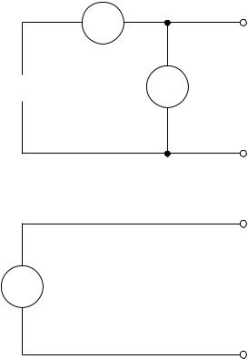
Figure 2-2
Simplified power supply diagram
A simplified diagram of the Model 2304A is shown in Figure 2-2. Note that it can read back
the output voltage (Vmeter) and current (Imeter). Display resolution for voltage readback is 1mV. There are two ranges for current readback: 5A and 5mA. On the 5A range, display resolution is 100 A, and on the 5mA range, resolution is 0.1 A.
The Model 2304A also has a digital voltmeter (DVM) that is independent of the power supply circuit. The DVM can measure up to +20V (1mV resolution).
When used with a pulsed load, the Model 2304A can read back peak current, idle current, and average current. See “Pulse-current measurements” for details. A long integration (up to 60 seconds) function is provided to measure average current of a low frequency pulse (long period) or a series of pulses. See “Long integration current measurements” for details.
I meter |
+ |
Source |
V-Source |
V meter |
|
with I-Limit |
|
_
+
DVM Digital
Voltmeter
_

2-4 Front Panel Operation
Power-up
Line power connection
The Model 2304A operates from a line voltage in the range of 100 to 240V at a frequency of 50 or 60Hz. Line voltage and frequency are automatically sensed, therefore there are no switches to set. Check to see that the line power in your area is compatible.
Perform the following steps to connect the power supply to the line power and turn it on:
1.Before plugging in the power cord, make sure the front panel power switch is in the off
(0) position.
2.Connect the female end of the supplied power cord to the AC receptacle on the rear panel.
WARNING The power cord supplied with the Model 2304A contains a separate ground for use with grounded outlets. When proper connections are made, instrument chassis is connected to power line ground through the ground wire in the power cord. Failure to use a grounded outlet may result in personal injury or death due to electric shock.
3.Turn on the power supply by pressing the front panel power switch to the on (1) position.
Front Panel Operation |
2-5 |
|
|
Fuse replacement
A rear panel fuse protects the power line input of the power supply. If the line fuse needs to be replaced, perform the following steps:
1.The fuse is located in a drawer below the AC receptacle (see Figure 2-1B). At the top of the fuse drawer is a small tab. At this location, use a thin-bladed knife or screwdriver to pry the fuse drawer open.
2.Slide the fuse drawer out to gain access to the fuse. Note that the fuse drawer does not pull all the way out of the power module.
3.Snap the fuse out of the drawer and replace it with the same type (250V, 2.5A, 5 × 20mm slo-blo). The Keithley part number is FU-106-2.5.
CAUTION For continued protection against fire or instrument damage, only replace the fuse with the type and rating listed. If the instrument repeatedly blows fuses, locate and correct the cause of the problem before replacing the fuse.
4.Push the fuse drawer back into the power module.
Power-up sequence
On power-up, the Model 2304A performs self-tests on its EPROM and RAM.
NOTE If a problem develops while the instrument is under warranty, return it to Keithley
Instruments Inc., for repair.
If the instrument passes the self-tests, the following information is briefly displayed:
•Top line — The model number (2304A) and the IEEE-488 address is displayed. At the factory, the address is set to 16.
•Bottom line — Firmware revision levels are displayed for the main board and the display board. Also displayed is the detected line frequency.
After the power-up sequence, the instrument goes to Actual V and I display type with the output off.

2-6 Front Panel Operation
Default settings
The power supply can be set to power-on to the factory default conditions (RST defaults) or to user-saved setup conditions. The factory default conditions are listed in Table 2-1.
The user can save up to five setups in memory (SAV0, SAV1, SAV2, SAV3, and SAV4). A setup can be saved in memory using the SAVE SETUP item of the MENU. The POWER ON SETUP item of the MENU is used to specify the power-on setup (RST or one of the user-saved setups).
The power supply can be returned to the RST or a user-saved default setup at any time by using the RECALL SETUP item of the MENU.
Table 2-1
Factory defaults (RST)
Setting |
RST default |
|
|
Output value settings: |
|
Voltage (V) |
0.000V |
Current (A) |
0.2500A |
Operate |
Off |
Display type |
Actual V and I |
GPIB address |
No effect (factory set to 16) |
Current range |
5 amps |
Integration rate |
1.00 PLC |
Average readings |
1 |
Power on setup |
No effect (factory set to 16) |
Current limit mode |
Lim |
Output relay 1 |
No effect (after power cycle, set to zero) |
Output relay 2 |
No effect (after power cycle, set to zero) |
Output response |
Normal |
Pulse current: |
|
High time |
33µsec |
Low time |
33µsec |
Average time |
33µsec |
Average readings |
1 |
Trigger delay |
0.00000 sec |
Trigger level |
0.000A |
Long integration: |
|
Integration time |
1 second |
Pulse timeout |
16 seconds |
Trigger edge |
Rising |
Trigger level |
0.000A |
|
|
Front Panel Operation |
2-7 |
|
|
Display types
For voltage and current readings, there are four display types. They are described as follows:
•ACTUAL V AND I — This display type is used to read back the actual output voltage and current. The power supply goes to this display type on power-up.
•DVM INPUT — This type is used to display the DC voltage applied to the DVM input of the power supply.
•PULSE CURRENT — This type is used to display high, low, or average pulse-current measurements.
•LONG INTEGRATION — This type is used to display average current measurements of a pulse or pulses using the long integration method.
A display type is selected as follows:
1.Press the DISPLAY key and use the or key to display the desired type; ACTUAL V AND I, DVM INPUT, PULSE CURRENT, or LONG INTEGRATION.
2.With the desired type displayed, press ENTER. Note that after selecting PULSE CURRENT, use the or key to select the desired pulse measurement: pulse high, pulse low, or pulse average. Examples of the display types are shown as follows:
Actual V and I: |
6.116V |
NL |
ON |
|
1.2058A |
|
|
DVM input: |
DVM INPUT |
NL |
ON |
|
4.993V |
|
|
Pulse current: |
PULSE HI |
NL |
ON |
|
2.1947A |
|
|
|
PULSE LO |
NL |
ON |
|
0.2147A |
|
|
|
PULSE AVG |
NL |
ON |
|
1.1495A |
|
|
Long integration: LONG INT |
NL |
ON |
|
|
1.0236A |
|
|
NOTES “NL” indicates that the normal output response is selected. With the enhanced output response selected, “EN” is displayed. See “Enhanced output response” for details.
“ON” indicates that the output is turned on. With the output turned off, “OFF” is displayed.
For the pulse current and Long Integration display types, “NO PULSE” is displayed if the output is off or pulses are not detected (output on). See “Pulse-current measurements” and “Long integration current measurements” for details.
When a change is made that effects the readings being taken, dashes are displayed instead of readings. The dashes remain until a valid reading for the new condition is taken.
2-8 Front Panel Operation
Remote display option
If the Model 2304A must be mounted in a location where the display is not readily visible or the controls are not easily accessible, the optional Model 2304-DISP Display Module can be used. This display module includes all instrument controls and has a nine foot cable so the power supply can be operated remotely from a more convenient location.
The remote display module plugs into the rear panel connector labeled “REMOTE DISPLAY OPTION” (Figure 2-1B). When plugged in, the main display module is disabled with the following message displayed:
REMOTE PANEL
ENABLED
When the remote display module is unplugged, control returns to the main display module.
Test connections
WARNING When installing a unit into a test system, make sure the external power sources do not apply voltage to the Model 2304A in excess of its maximum limits (see specifications). Failure to do so could result in personal injury or death.
Test connections to the power supply are made at the rear panel using a quick disconnect OUTPUT/DVM IN connector. (Figure 2-1B shows where the connector plugs in.) Use up to #14 AWG wire for the screw terminals of the connector. Once the connector is wired up, plug it into the rear panel and tighten the captive retaining screws.
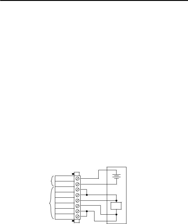
Figure 2-3 shows typical power supply connections to the DUT.
Figure 2-3 |
|
External |
|
Typical connections |
Quick |
Test |
|
|
Circuitry |
||
|
Disconnect |
|
|
|
Connector |
+ |
|
|
|
||
DVM |
DVM + |
_ |
|
Input |
DVM - |
|
|
|
|
||
|
Source - |
|
|
|
Source - |
|
|
Output |
Sense - |
|
|
Sense + |
DUT |
||
|
|||
|
Source + |
|
|
|
Source + |
|
Front Panel Operation |
2-9 |
|
|
Setting voltage and current values
Output voltage can be set from 0 to 20V, and there are three range selections for current (5 AMPS, 5 MILLIAMPS, and AUTO). The maximum current limit setting for the 5 AMPS and AUTO ranges is 5A. The maximum limit for the 5 MILLIAMPS range is 1A.
The current limit setting for the 5 AMPS and AUTO ranges is “remembered” by that range. For example, assume the current limit setting on the 5 AMPS range is 3A. Selecting the 5 MILLIAMPS range defaults the current limit setting to 1A since that is the maximum allowable setting on that range. Toggling back to the 5 AMPS range reinstates the 3A limit. If the current limit value on the 5 AMPS range is set to ≤1A, the limit on the 5 MILLIAMPS range will be the same.
When the current limit is reached, the power supply can be set to either turn off (trip) or remain on. If set to remain on, the power supply output current will not exceed the set current limit value. See “Current limit” for details.
Procedure to edit voltage and current values
The following procedure assumes that the appropriate current range is already selected.
Remember, the maximum current limit setting on the 5 MILLIAMPS range is 1A.
Editing keys — Once in the Output Settings Mode, the four editing keys ( , , , and ) are used to set values. Cursor position (blinking digit) is controlled by the and keys. With the cursor positioned on a digit, increment or decrement the value using the and keys.
Perform the following steps to edit voltage and current values:
NOTE When in the enhanced output response mode, the maximum output voltage setting is 15V. See “Enhanced output response” for details.
1.Press the SET key to select the Output Settings Mode. A blinking cursor appears in the voltage field of the display.
2.Use the , , , and keys to key in the desired output voltage value and press SET. The blinking cursor moves to the current field of the display.
3.Use the , , , and keys to key in the desired current limit and press SET to exit from the Output Settings Mode or front panel menu.

2-10 Front Panel Operation
Editing shortcuts
With the Output OFF, the following editing shortcuts can be used:
•Output voltage can be quickly set to the maximum value by incrementing the tens digit (MSD). Note that if the tens digit is zero, it is not displayed. Place the cursor to the left of the units digit.
•Output voltage can be quickly set to zero (0.000 V) by decrementing the first leading zero of the reading. If there is no leading zero, decrement the tens digit.
•Current limit on the 5A range can be quickly set to its maximum value by incrementing the units digit (MSD).
•Current limit on either range (5A or 5mA) can be quickly set to the minimum value (0.0001A) by decrementing the first leading zero of the reading. If there is no leading zero, decrement the units digit.
Editing restrictions
With the Output ON, the following editing restrictions are in effect:
•You cannot increment a digit that would display a value that exceeds the maximum. For example, for the value 19.200V, you cannot increment the “1” or the “9” since the resultant value would exceed 20.000V.
•When decrementing a digit, only that digit and digits to the left are affected. The digits to the right of the cursor are not changed.
NOTES
•The SET key is active in any front panel menu or display mode. If not already in the Output Settings Mode, the SET key will select it.
•The V and I DACs are updated in real time. Therefore, if the output is on, the output is updated immediately when a value is altered.
•After pressing SET to exit the Output Settings Mode, the instrument returns to the previous display mode or front panel menu.
OPERATE
The OPERATE key is used to control the output of the power supply. This key toggles the output between on and off. While in one of the display modes, output ON or OFF is displayed in the upper right corner of the display. The key is active in any front panel menu or display mode. In menus, the state is not displayed.
Front Panel Operation |
2-11 |
|
|
Output readback
With the ACTUAL V AND I display type selected (see “Display types”) and in the Readback Mode, the actual output voltage and current are measured and displayed. The Readback Mode is selected if there is no blinking cursor in the display. If in the Output Settings Mode (blinking cursor), keep pressing SET until the display returns to the Readback Mode.
There are three range selections for current readback: 5A, 5mA, or AUTO. With AUTO selected, the instrument automatically goes to the most sensitive range to perform the measurement. Range selection is performed from the CURRENT RANGE item of the MENU (see “MENU”).
The voltage and current readings that are displayed are controlled by the integration rate and the specified average readings count. In general, the integration rate defines the measurement speed of the instrument, and the average readings count specifies how many measurements are performed and averaged for each displayed reading. These aspects of operation are selected from the INTEGRATION RATE and AVERAGE READINGS items of the MENU. (See “MENU” for details.)
Current limit
If the current limit is reached, the output will either turn off (trip) or stay on. The current limit mode (TRIP or LIM) is selected from the “CURRENT LIM MODE” item of the MENU. (See “MENU” for details.)
LIM mode — With the LIM mode selected, the output will remain on when the current limit is reached. The “LIM” message will appear on the lower line of the display, after the current reading indicator (A or mA). The message will clear when the limit condition is cleared.
The power supply can be taken out of current limit by decreasing the output voltage or increasing the current limit value. Note that increasing the current limit may compromise protection for the DUT.
While in current limit, the power supply is operating as a constant-current source. As long as the limit condition exists, the power supply output current will remain constant. Note that the output voltage is probably less than the programmed value when sourcing current, and probably greater than the programmed value when sinking current.
TRIP mode — With the TRIP mode selected, the output will turn off when the current limit is reached. The “TRIP” message will appear on the lower line of the display, after the current reading indicator (A or mA). The message will clear when the output is turned back on, assuming it does not trip again due to a current limit condition.

2-12 Front Panel Operation
Enhanced output response
The power supply has an enhanced output response mode to improve transient response to load changes. It improves transient recovery time and reduces the transient voltage drop. See Appendix A, “Specifications, Transient response 1000% load change,” for details.
With enhanced output response selected, maximum output voltage is reduced to 15V. When operating as a sink, maximum power with the enhanced output response mode selected is 15W.
The normal response mode is the RST default condition. Output response is checked or changed from the OUTPUT RESPONSE item of the MENU. Note that the output response mode cannot be changed while the output is on or the output voltage setting exceeds that response type limitation.
NOTE When displaying readings, the output response mode is also displayed. For the normal response mode, “NL” is displayed. For the enhanced response mode, “EL” is displayed.
Independent voltage measurements (DVM)
The Model 2304A has an independent digital voltmeter (DVM) that can measure up to +20VDC. Connections for the DVM are shown in Figure 2-3. The DVM INPUT display type must be selected to use the DVM. (See “Display types.”)
Pulse-current measurements
The Model 2304A can perform current measurements for pulsing loads. The built-in measurements include:
•Peak measured current — measures the peak (high) current of the pulse train.
•Idle measured current — measures the idle (low) current of the pulse train.
•Average transmit current — measures the average current of the pulse train.
The high, low, and average measurements of a pulse are illustrated in Figure 2-4. The high measurement is triggered on the rising edge of the pulse, and an integration is performed while the pulse is high for the time specified for the high measurement. The falling edge of the pulse triggers the low measurement, and an integration is performed for the time specified for the low measurement. An average measurement is triggered on the rising edge, and the integration covers both the high and low periods of the pulse as specified by the average measurement time settings.
NOTE Another measurement of pulse currents, digitization, is available over the bus. Refer to the :SENS:PCUR:SYNC:STAT command in Section 4 for details.

Front Panel Operation |
2-13 |
|
|
Trigger level — To avoid false pulse detection, you can use a trigger level of up to 5A. All pulses, noise, or other transients that are less than the set trigger level will be ignored.
Trigger delay — When a pulse is detected, there is a 25µsec code execution delay before the integration period begins. An additional trigger delay can be used to allow leading edge pulse overshoot to settle. The integration period will not start until the trigger delay period expires.
Note that a large trigger delay will slow down power supply operation.
Integration times — The three integration time periods for pulse measurements can be set automatically or manually by the user. When the PULSE AUTO TIME operation is performed, the instrument measures the high and low periods of the detected pulse and sets appropriate integration times. The three integration times apply for all subsequent pulse measurements until another PULSE AUTO TIME is performed or the times are changed manually. The PULSE AUTO TIME feature can detect pulses in the 80 sec to 833msec range.
You can manually set the PULSE HIGH TIME, PULSE LOW TIME, and PULSE AVG TIME. In general, the longer the integration period, the more accurate the measurement. However, you must make sure that an integration period does not extend into the wrong portion of the pulse or into the next pulse. For example, if the pulse is high for 600 sec, the high integration time must be less than 600 sec. If not, you will integrate a low portion of the pulse, and the high pulse measurement will therefore be erroneous. Be sure to factor in trigger delay when determining integration times.
Average readings count — The average readings count specifies how many measurements (integrations) are performed and averaged for each displayed reading. For example, assume that the pulse average readings count is 10 and you are measuring PULSE HIGH. Each displayed reading will reflect the average of 10 peak pulse measurements.
Figure 2-4
Pulse-current measurement
 High
High 
 Low
Low 
Average
 High and average measurement triggered on leading edge of pulse
 Low measurement triggered on falling edge of pulse

2-14 Front Panel Operation
Pulse current digitization
The following discussion explains how to digitize a current waveform. A programming example at the end of this section demonstrates proper command sequence for pulse current digitization.
With pulse current digitization selected, readings are taken at a constant integration time of 33µsec across the pulse or pulse train. The message “DIGITIZE” is displayed instead of readings. Pulse current digitization is selected by disabling trigger synchronization:
SENS:PCUR:SYNC <b>
<b> = |
OFF |
Select pulse current digitization (trigger synchronization disabled). |
= |
ON |
Select pulse current measurements (trigger synchronization enabled). |
The commands to set the trigger level and trigger delay for pulse current measurements also apply for pulse current digitization. However, the trigger delay can be set for up to five seconds.
SENS:PCUR:SYNC:DEL <NRf>
<NRf> = 0 to 5 Trigger digitization delay in seconds (10µsec steps).
Note that the “NO PULSE” message will be displayed if the pulse is not detected.
When the pulse is detected, the digitization process syncs up to the edge specified by the following command:
SENS:PCUR:MODE <name> |
|
|
<name> = |
HIGH or AVER |
Sync up to rising edge of pulse. |
= |
LOW |
Sync up to falling edge of pulse. |
After any specified delay period expires, the instrument takes the number of readings specified by the average count command:
SENS:PCUR:AVER <NRf> |
|
<NRf> = 1 to 5000 |
Digitize 1 to 5000 readings. |
NOTE Although the integration time is 33µsec, some processing time is needed between readings. The time between readings, including integration and processing time, is about 278µsec.
Front Panel Operation |
2-15 |
|
|
Programming examples
Pulse current measurements
The following command sequence will return the average of 10 peak pulse current measurements:
SENS:RANG 5 |
' Select 5A range. |
VOLT 15 |
' Set output voltage to 15V. |
CURR 0.75 |
' Set current limit to 750mA. |
OUTP ON |
' Turn output on. |
SENS:PCUR:AVER 10 |
' Set average count to 10. |
SENS:PCUR:TIME:AUTO |
' Set integration times automatically. |
SENS:PCUR:SYNC:TLEV 0.1 |
' Set trigger level to 100mA. |
SENS:PCUR:SYNC:DEL 50e-3 |
' Set trigger delay to 50msec. |
SENS:FUNC “PCUR” |
' Select pulse current function. |
SENS:PCUR:SYNC ON |
' Enable trigger synchronization. |
SENS:PCUR:MODE HIGH |
' Configure to measure peak pulse. |
READ? |
' Trigger 10 measurement conversions and |
|
' return the average of those 10 conversions. |
Pulse current digitization
The following command sequence returns 3600 digitized readings. It will take approximately one second to perform the measurement process.
SENS:RANG 5 |
' Select 5A range. |
|
VOLT 15 |
' Set output voltage to 15V. |
|
CURR 0.75 |
' Set current limit to 750mA. |
|
OUTP ON |
' Turn output |
on. |
SENS:PCUR:SYNC OFF |
' Disable trigger synchronization. |
|
SENS:PCUR:AVER 3600 |
' Set average count to 3600. |
|
SENS:PCUR:SYNC:TLEV 0.1 |
' Set trigger level to 100mA. |
|
SENS:PCUR:SYNC:DEL 50e-3 |
' Set trigger delay to 50msec. |
|
SENS:FUNC “PCUR” |
' Select pulse current function. |
|
READ:ARR? |
' Trigger and return 3600 readings. |
|

2-16 Front Panel Operation
Pulse-current measurement procedure
The following steps summarize the procedure to perform pulse measurements:
1.From the PULSE CURRENT item of the MENU (see “MENU” for details), set the trigger level and delay, integration times, and average readings count.
2.Set the output voltage and current limit, and press OPERATE.
3.Press the DISPLAY key and select the PULSE CURRENT display type.
4.Use the or key to display the desired pulse measurement: PULSE HIGH, PULSE LOW, or PULSE AVG.
NOTES If no pulses are detected, current will not be measured (i.e., -----A) and the “NO PULSE” message will be displayed. The “NO PULSE” message is displayed with dashes or the last valid pulse reading. Dashes are shown if the pulse-current measurement settings are not appropriate for detecting pulses. The last valid pulse reading is shown if the pulse disappears while taking background readings and no change in pulse settings was made.
Pulses are not detected with the output off. With the output on, pulses will not be detected if the trigger level is too low or too high. Perform the following procedure to find an appropriate trigger level. Make sure the voltage and current settings are appropriate for detecting pulses.
Determining correct trigger level
1.Turn on the output.
2.Select the PULSE CURRENT display type. If the trigger level is too low or too high, the “NO PULSE” message will be displayed. If pulse-current measurements are instead being displayed, the trigger level is valid. You can skip the rest of this procedure.
3.Go into the MENU, select PULSE CURRENT, and then TRIGGER LEVEL. (See “MENU” for details.)
4.Change the PULSE TRIG LEVEL and press ENTER. If the trigger level is still too low or too high, the “A/D PULSE TRIG NOT DETECTED” message will be displayed briefly. Note that it may take a few seconds for the message to appear.
5.If the message appeared, repeat step 4 until a valid trigger level is found.
6.Use the MENU key to back out of the menu structure and display pulse-current measurements.
 Loading...