


W 800
Table of contents
 Loading...

Motorcycle
Owner's Manual
ENGLISH
Original instructions

Whenever you see the symbols
shown below, heed their instructions!
Always follow safe operating and maintenance practices.
DANGER
DANGER indicates a hazardous
situation which, if not avoided,
will result in death or serious injury.
WARNING
WARNING indicates a hazardous
situation which, if not avoided,
could result in death or serious
injury.
NOTICE
NOTICE is used to address practices not related to personal injury.
NOTE
NOTE indicates information that may
○
help or guide you in the operation or
service of the vehicle.

NOTICE
THIS PRODUCT HAS BEEN MANUFACTURED FOR USE IN A
REASONABLE AND PRUDENT
MANNER BY A QUALIFIED OPERATOR AND AS A VEHICLE ONLY.

FOREWORD
Congratulations on yo ur purchase of a new Kawasaki motorcycle. Your new motorcycle is the product of Kawasaki's advanced engineering, exhaustive testing,
and continuous striving for superior reliability, safety and performance.
Please read this Owner's Manual carefully before riding so that you will be
thoroughly familiar with the proper operation of your motorcycle's controls, its features, capabilities, and limitations. This manual offers many safe riding tips, but its
purpose is not to provide instruction in all the techniques and skills required to ride
a motorcycle safely. Kawasaki strongly recommends that all operators of this vehicle enroll in a motorcycle rider training program to attain awareness of the mental
and physical requirements necessary for safe motorcycle operation.
To ensure a long, trouble-free life for your motorcycle, give it the proper care and
maintenance described in this manual. For those who would like more detailed information on their Kawasaki Motorcycle, a Service Manual is available for purchase from any authorized Kawasaki motorcycle dealer. The Service Manual
contains detailed disassembly and maintenance information. Those who plan to do
their own work should, of course, be competent mechanics and possess the special tools described in the Service Manual.

Keep this Owner's Manual aboard your motorcycle at all times so that you can re-
fer to it whenever you need information.
This manual should be considered a permanent part of the motorcycle and
should remain with the motorcycle when it is sold.
All rights reserved. No part of this publication may be reproduced without our pri-
or written permission.
This publication includes the latest information available at the time of printing.
However, there may be minor differences between the actual product and illustrations and text in this manual.
All products are subject to change without prior notice or obligation.
KAWASAKI HEAVY INDUSTRIES, LTD.
Motorcycle & Engine Company
© 2014 Kawasaki Heavy Industries, Ltd. Jun. 16, 2014. (1)


TABLE OF CONTENTS
SPECIFICATIONS ................................ 10
LOCATION OF PARTS ........................ 13
LOADING INFORMATION ................... 16
GENERAL INFORMATION .................. 19
Meter Instruments .............................. 19
Speedometer and Tachometer ...... 20
LCD (Clock, Odometer, Trip Meter) 21
Warning/Indicator Lights ................ 24
Key ..................................................... 26
Ignition Switch/Steering Lock ............ 26
Right Handlebar Switches ................. 28
Engine Stop Switch: ...................... 28
Starter Button: ................................ 29
Left Handlebar Switches .................... 29
Dimmer Switch: .............................. 29
Turn Signal Switch: ........................ 30
Horn Button: ................................... 30
Brake/Clutch Lever Adjuster .............. 30
Fuel Tank Cap .................................... 31
Fuel .................................................... 32
Fuel Requirement: ......................... 32
Filling the Tank: .............................. 34
Stands ................................................ 35
Seat .................................................... 37
Helmet Hook/Holding Cable .............. 38
Tool Kit ............................................... 40
Document Compartment ................... 40
Tying Hooks ....................................... 41
Rear View Mirror ................................ 41
BREAK-IN ............................................ 43
HOW TO RIDE THE MOTORCYCLE .. 45
Starting the Engine ............................ 45
Jump Starting ..................................... 47
Moving Off .......................................... 50
Shifting Gears .................................... 51
Braking ............................................... 52
Stopping the Engine .......................... 53
Stopping the Motorcycle in an Emer-
gency .............................................. 54
Parking ............................................... 55

Catalytic Converter ............................ 57
SAFE OPERATION .............................. 59
Safe Riding Technique ....................... 59
Daily Checks ...................................... 62
Additional Considerations for High
Speed Operation ............................ 65
MAINTENANCE AND ADJUSTMENT 67
Periodic Maintenance Chart .............. 68
Engine Oil .......................................... 77
Spark Plugs ....................................... 83
Kawasaki Clean Air System .............. 84
Valve Clearance ................................. 85
Air Cleaner ......................................... 86
Throttle Control System ..................... 90
Engine Vacuum Synchronization ....... 93
Idle Speed .......................................... 93
Clutch ................................................. 95
Drive Chain ........................................ 96
Brakes ................................................104
Brake Light Switch .............................109
Front Fork .......................................... 111
Rear Shock Absorber ........................112
Wheels ............................................... 116
Spoke and Rim: ............................. 119
Battery ................................................120
Headlight Beam .................................126
Fuses .................................................128
General Lubrication ...........................130
Cleaning Your Motorcycle ..................131
STORAGE ............................................137
ENVIRONMENTAL PROTECTION ..... 139
LOCATION OF LABELS ...................... 140

10
SPECIFICATIONS
SPECIFICATIONS
PERFORMANCE
Maximum Horsepower 35 kW (48 PS) @6 500 r/min (rpm)
Maximum Torque
Minimum Turning Radius 2.7 m (8.9 ft)
DIMENSIONS
Overall Length 2 190 mm (86.22 in.)
Overall Width 790 mm (31.10 in.)
Overall Height 1 075 mm (42.32 in.)
Wheelbase 1 465 mm (57.68 in.)
Road Clearance 125 mm (4.92 in.)
Curb Mass 217 kg (478 lb)
ENGINE
Type SOHC, 2-cylinder, 4-stroke, air-cooled
Displacement 773 cm
Bore × Stroke 77.0 × 83.0 mm (3.03 × 3.27 in.)
Compression Ratio 8.4 : 1
Starting System Electric starter
Cylinder Numbering Method Left to right, 1-2
Firing Order 1-2
Fuel System FI (Fuel Injection)
60 N·m (6.1 kgf·m, 44.3 ft·lb) @2 500 r/min (rpm)
3
(47.2 cu in.)

SPECIFICATIONS 11
Ignition System Battery and coil (transistorized ignition)
Ignition Timing 0° BTDC @1 200 r/min (rpm)
Spark Plug NGK CR8E
Lubrication System Forced lubrication (wet sump)
Engine Oil Type :
API SG, SH, SJ, SL or SM with JASO MA, MA1 or
MA2
Viscosity: SAE 10W-40
Capacity : 3.2 L (3.4 US qt)
TRANSMISSION
Transmission Type 5-speed, constant mesh, return shift
Clutch Type Wet, multi disc
Driving System Chain drive
Primary Reduction Ratio 2.095 (88/42)
Final Reduction Ratio 2.467 (37/15)
Overall Drive Ratio 4.403 (Top gear)
Gear Ratio 1st 2.353 (40/17)
2nd 1.591 (35/22)
3rd 1.240 (31/25)
4th 1.000 (28/28)
5th 0.852 (23/27)
FRAME
Caster 27°

12 SPECIFICATIONS
Trail 108 mm (4.3 in.)
Tire Size: Front 100/90-19M/C 57H
Rear 130/80-18M/C 66H
Rim Size: Front J19 × 2.15
Rear J18M/C × MT2.75
Fuel Tank Capacity 14 L (3.7 US gal)
ELECTRICAL EQUIPMENT
Battery 12 V 10 Ah (10 HR)
Headlight
Brake/Tail Light
High beam 12 V 60 W
Low beam 12 V 55 W
12 V 21/5 W
Specifications are subject to change without notice, and may not apply to every
country.
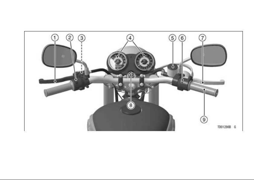
LOCATION OF PARTS
LOCATION OF PARTS
13
1. Clutch Lever
2. Left Handlebar Switches
3. Starter Lockout Switch
4. Meter Instruments
5. Brake Fluid Reservoir (Front)
6. Right Handlebar Switches
7. Front Brake Lever
8. Ignition Switch/Steering Lock
9. Throttle Grip
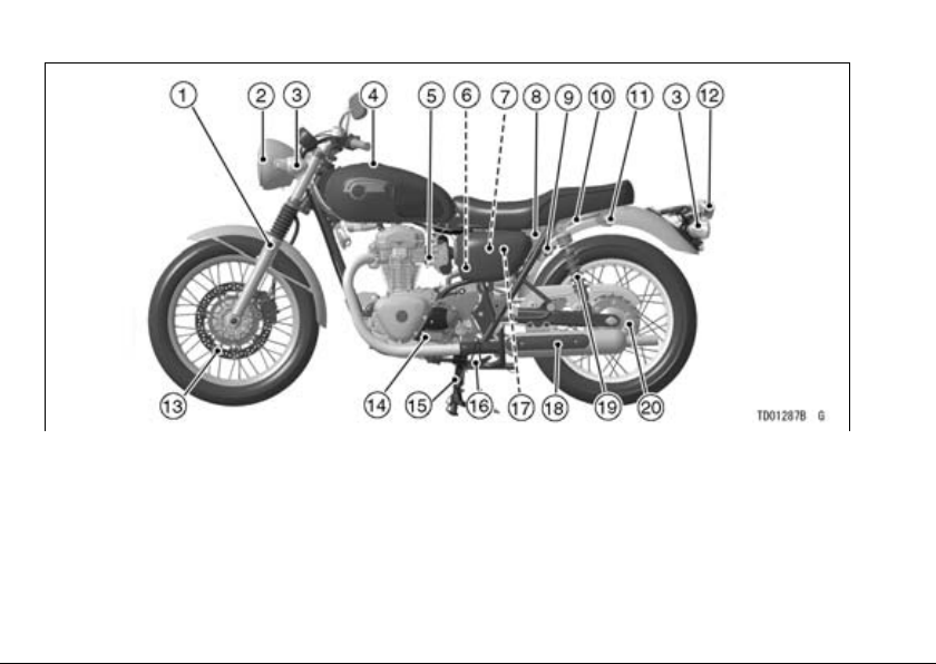
14 LOCATION OF PARTS
1. Front Fork
2. Headlight
3. Turn Signal Lights
4. Fuel Tank Cap
5. Idle Adjusting Screw
6. Air Cleaner Element
7. Junction Box (Fuse Box)
8. Seat Lock
9. Helmet Hook
10. Grab Rail
11. Tying Hook
12. Tail/Brake Light
13. Brake Disc
14. Shift Pedal
15. Center Stand
16. Side Stand
17. Battery
18. Muffler
19. Rear Shock Absorber
20. Drive Chain
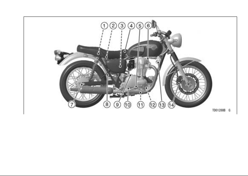
LOCATION OF PARTS
15
1. Helmet Holding Cable
2. Tool Kit
3. Air Cleaner Element
4. Seat
5. Rear Brake Pedal
6. Spark Plugs
7. Brake Lining Wear Indicator
8. Rear Brake Light Switch
9. Oil Filler Cap
10. Oil Level Inspection Window
11. Oil Drain Bolt
12. Oil Filter
13. Horn
14. Brake Caliper
16 LOADING INFORMATION
LOADING INFORMATION
WARNING
Incorrect loading, improper installation or use of accessories,
or modification of your motorcycle may result in an unsafe riding condition. Before you ride the
motorcycle, make sure it is not
overloaded and that you have followed these instructions.
With the exception of genuine Kawasaki Parts and Accessories, Kawasaki
has no control over the design or application of accessories. In some cases,
improper installation or use of accessories, or motorcycle modification, will
void the motorcycle warranty, can negatively affect performance, and can
even be illegal. In selecting and using
accessories, and in loading the motorcycle, you are personally responsible
for your own safety and the safety of
other persons involved.
NOTE
Kawasaki Parts and Accessories
○
have been specially designed for
use on Kawasaki motorcycles. We
strongly recommend that all parts
and accessories you add to your motorcycle be genuine Kawasaki components.
Because a motorcycle is sensitive to
changes in weight and aerodynamic
forces, you must take extreme care in
carrying cargo, passengers and/or in
the fitting of additional accessories.
The following general guidelines have

been prepared to assist you in making
your determinations.
1. Any passenger should be thoroughly familiar with motorcycle operation. The passenger can affect
control of the motorcycle by improper positioning during cornering and
sudden movements. It is important
that the passenger sit still while the
motorcycle is in motion and not interfere with the operation of the motorcycle. Do not carry animals on
your motorcycle.
2. You should instruct any passenger
before riding to keep his feet on the
passenger footpegs and hold on to
the operator or grab rail. Do not
carry a passenger unless he or she
is tall enough to reach the footpegs
and footpegs are provided.
3. All baggage should be carried as
low as possible to reduce the effect
on the motorcycle center of gravity.
LOADING INFORMATION 17
Baggage weight should also be distributed equally on both sides of the
motorcycle. Avoid carrying baggage
that extends beyond the rear of the
motorcycle.
4. Baggage should be securely attached. Make sure that the baggage will not move around while
you are riding. Recheck baggage
security as often as possible (not
while the motorcycle is in motion)
and adjust as necessary.
5. Do not carry heavy or bulky items
on a luggage rack. They are designed for light items, and overloading can affect handling due to
changes in weight distribution and
aerodynamic forces.
6. Do not install accessories or carry
baggage that impairs the performance of the motorcycle. Make sure
that you have not adversely affected any lighting components,

LOADING INFORMATION
18
road clearance, banking capability
(i.e., lean angle), control operation,
wheel travel, front fork movement,
or any other aspect of the motorcycle's operation.
7. Weight attached to the handlebar
or front fork will increase the mass
of the steering assembly and can
result in an unsafe riding condition.
8. Fairings, windshields, backrests,
and other large items have the capability of adversely affecting stability and handling of the motorcycle,
not only because of their weight,
but also due to the aerodynamic
forces acting on these surfaces
while the motorcycle is in operation.
Poorly designed or installed items
can result in an unsafe riding condition.
9. This motorcycle was not intended
to be equipped with a sidecar or to
be used to tow any trailer or other
vehicle. Kawasaki does not manufacture sidecars or trailers for motorcycles and cannot predict the
effects of such accessories on handling or stability, but can only warn
that the effects can be adverse and
that Kawasaki cannot assume responsibility for the results of such
unintended use of the motorcycle.
Furthermore, any adverse effects
on motorcycle components caused
by the use of such accessories will
not be remedied under warranty.
Maximum Load
Weight of rider, passenger, baggage, and
accessories must not exceed 183 kg (403
lb).

Meter Instruments
A. Speedometer
B. MODE Button
C. RESET Button
D. Tachometer
E. Red Zone
F. FI Warning Indicator Light
G. Oil Pressure Warning Indi-
cator Light
H. Right Turn Signal Indicator
Light
I. Fuel Level Warning Indicator
Light
J. Neutral Indicator Light
K. High Beam Indicator Light
L. Left Turn Signal Indicator
Light
M. LCD (Odometer/Trip Meter/
Clock)
GENERAL INFORMATION 19
GENERAL INFORMATION
20 GENERAL INFORMATION
Speedometer and Tachometer
The speedometer shows the speed
of the vehicle. The needle of the
speedometer and tachometer momentarily sweeps from the minimum to
maximum and back to minimum when
the ignition switch is turned to “ON”.
This checks the operation of the meter
needles. So if they do not operate correctly, have the function checked by an
authorized Kawasaki dealer.
The tachometer shows the engine
speed in the revolutions per minute (r/
min, rpm). On the right side of the tachometer face is a portion called the “red
zone.” Engine r/min (rpm) in the red
zone is above maximum recommended engine speed and is also
above the range for good performance.
NOTICE
Engine r/min (rpm) should not be
allowed to enter the red zone; operation in the red zone will overstress the engine and may cause
serious engine damage.
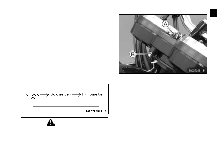
LCD (Clock, Odometer, Trip Meter)
The LCD (Liquid Crystal Display) located in the speedometer face is used
to display the Clock, Odometer and
Trip Meter. Pushing the MODE button
shifts the display through the following
three modes: CLOCK, ODO, and TRIP.
When the ignition switch is turned to
“ON”, all the LCD segments are displayed for three seconds, then the
clock or meters operate normally depending on the mode selected.
WARNING
For Safe ty, do not operate the meter buttons while riding the motorcycle.
GENERAL INFORMATION 21
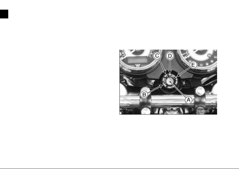
A. MODE Button
B. RESET Button
Clock -
To adjust the hours and minutes:
Turn the ignition switch to “ON”.
•
Push the MODE button to display
•
the clock.
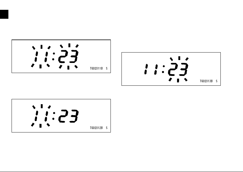
22 GENERAL INFORMATION
Push the RESET button for more
•
than two seconds. Both the hour and
minute displays start blinking.
Push the RESET button. The hour
•
display only blinks. Push the MODE
button to advance the hours.
Push the RESET button. The hour
•
display stops blinking and the minute
display starts blinking. Push the
MODE button to advance the minutes.
Push the RESET button. Both the
•
hour and minute displays start blinking again.
Push the MODE button. The dis-
•
plays stop blinking and the clock
starts working.
NOTE
Pushing the MODE button momen-
○
tarily advances the hour or minute
step by step. Pushing and holding
the button advance the hour or mi-
nute continuously.
The clock works normally from the
○
back-up power while the ignition
switch is turned off.
When the battery is disconnected,
○
the clock resets to 1:00 and starts
working again when the battery is
connected.
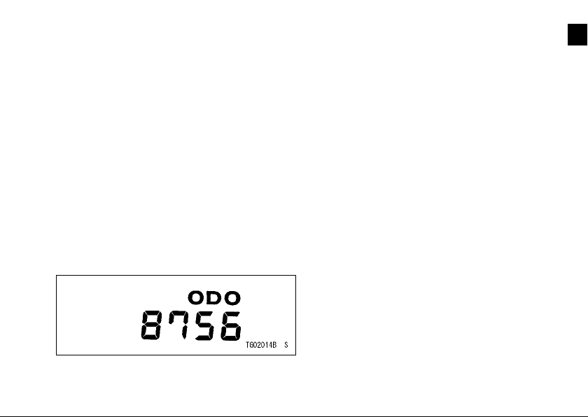
Odometer -
The odometer shows the total distance in kilometers the vehicle has
been ridden. This meter cannot be reset.
GENERAL INFORMATION 23
NOTE
The data is maintained even if the
○
battery is disconnected.
When the figures come to 999999,
○
they are stopped and locked.
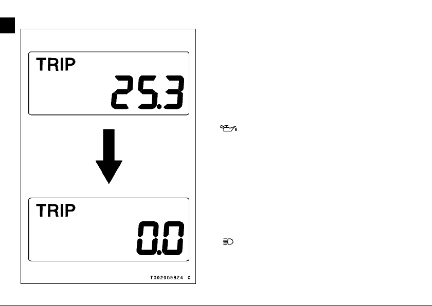
Trip Meter -
The trip meters show the distance in
kilometers traveled since it was last reset to zero.
To reset the trip meter:
Push the MODE button to display
•
the trip meter.
Push the MODE button and hold it
•
in.
After two seconds, the figure display
•
turns to 0.0, and then starts counting
when the vehicle is operated. The
meter counts until it is reset.
24 GENERAL INFORMATION
NOTE
The data is maintained even if the
○
battery is disconnected.
When the trip meter reaches 9999.9
○
while running, the meter reset to 0.0
and continues counting.
Warning/Indicator Lights
: The oil pressure warning indicator light goes on whenever the oil pressure is dangerously low or the ignition
switch is in the ON position with the engine not running, and goes off when
the engine oil pressure is high enough.
Refer to the Maintenance and Adjustment chapter for more detailed engine
oil information.
: When the headlight is on high
beam, the high beam indicator light is
lit.
: When the turn signal switch is
turned to left or right, the turn signal indicator light blinks on and off.
N : When the transmission is in neutral,
the neutral indicator light goes on.
FI: The fuel injection (FI) warning indicator light goes on when the ignition
switch is turned to “ON” and goes off
soon after ensuring that its circuit functions properly.
The warning indicator light also goes
on whenever the troubles occur in digital fuel injection system (DFI). If the
warning indicator light blinks on, have
the DFI system checked by an authorized Kawasaki dealer.
GENERAL INFORMATION 25
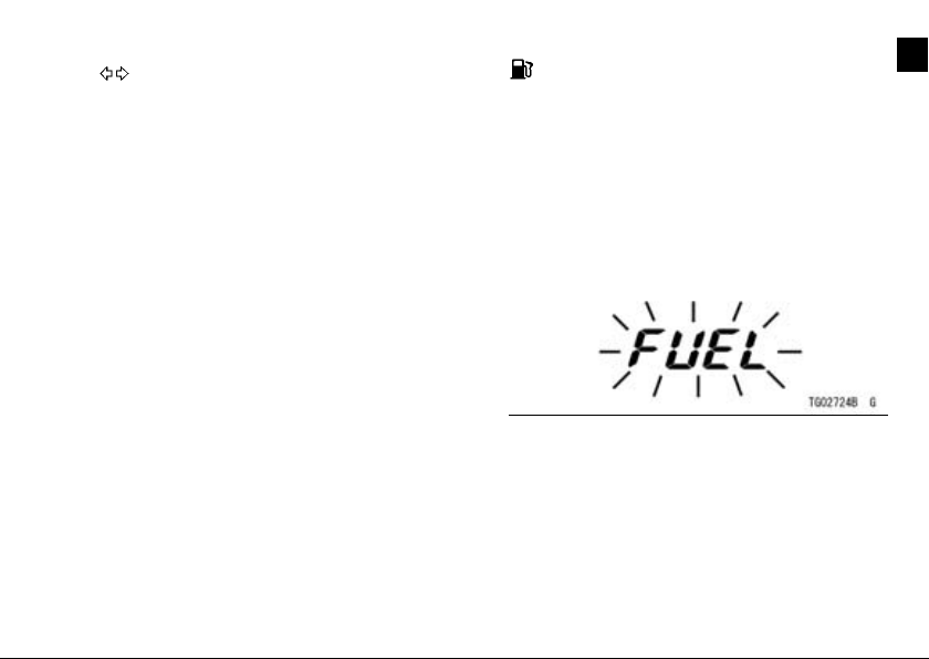
: The fuel level warning indicator
light goes on when the ignition switch
is turned to “ON” and goes off soon
after ensuring that its circuit functions
properly.
The warning indicator light also goes
on and “FUEL” blinks in the LCD when
approximately 3.1 L (0.8 US gal) of fuel
remains.
Refuel at the earliest opportunity
when the fuel level warning indicator
light goes on and “FUEL” blinks.
When vehicle stands with side stand,
fuel level warning indicator light cannot
show the amount of fuel in the fuel tank
exactly. Stand upright the vehicle to
check the fuel level.
26 GENERAL INFORMATION
Key
This motorcycle has a combination
key, which is used for the ignition
switch/steering lock, seat lock, helmet
hook and fuel tank cap.
Blank keys are available at your Kawasaki dealers. Ask your dealer to
make any additional spare keys you
may need, using your original key as a
master.
Ignition Switch/Steering Lock
This is a four-position, key-operated
switch. The key can be removed from
the switch when it is in the OFF, LOCK
or P (Park) position.
A. Ignition Switch/Steering Lock
B. LOCK position
C. OFF position
D. ON position
E. P (Park) position
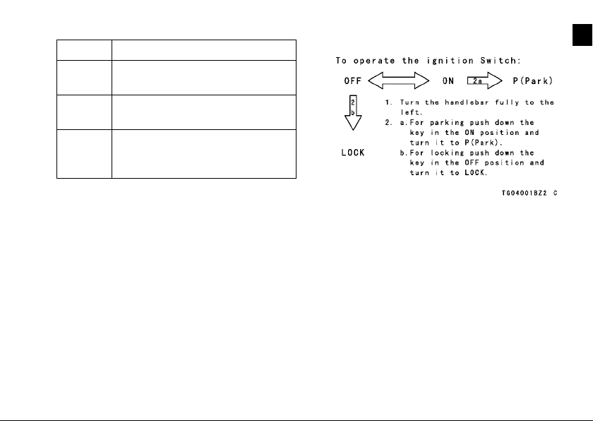
OFF Engine off. Electrical circuits off.
Engine on. All electrical equip-
ON
ment can be used.
LOCK
P (Park)
Steering locked. Engine off.
Electrical circuits off.
Steering locked. Engine off. Tail
and city lights on. Other electrical circuits cut off.
NOTE
The tail and city lights are on when-
○
ever the ignition switch is in the ON
position. One headlight goes on
when the starter button is released
after starting the engine. To avoid
battery discharge, always start the
engine immediately after turning the
ignition switch to “ON”.
If you leave the P (Park) position on
○
for a long time (one hour), the battery
may become totally discharged.
GENERAL INFORMATION 27
28 GENERAL INFORMATION
Right Handlebar Switches
Engine Stop Switch:
In addition to the ignition switch, the
engine stop switch must be in
the
operate.
gency use. If required, move the switch
to the
position for the motorcycle to
The engine stop switch is for emer-
position.
NOTE
Although the engine stop switch
○
stops the engine, it does not turn off
all the electrical circuits. Ordinari ly,
the ignition switch should be used to
stop the engine.
A. Engine Stop Switch
B. Starter Button
Starter Button:
The starter button operates the electric starter when the transmission is in
neutral.
Refer to the Starting the Engine section of the "How to Ride the Motorcycle" chapter for starting instructions.
GENERAL INFORMATION 29
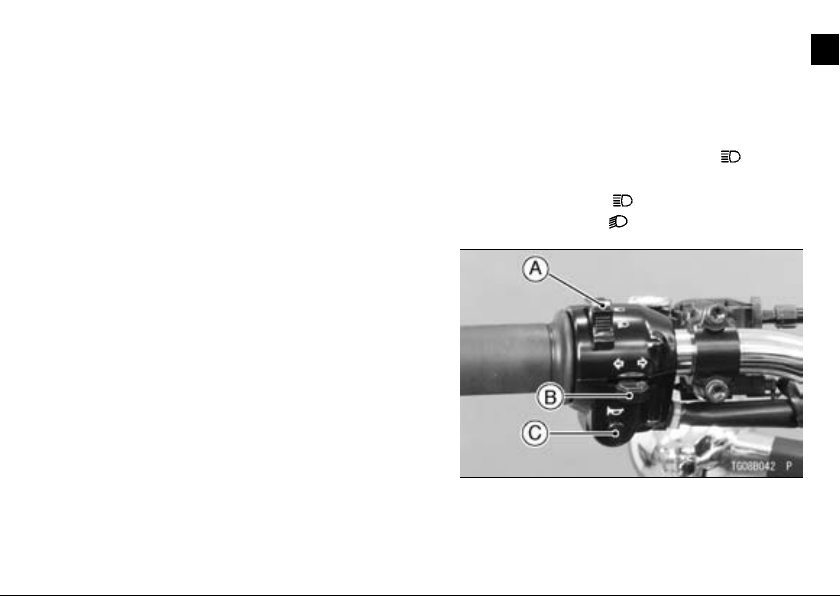
Left Handlebar Switches
Dimmer Switch:
High or low beam can be selected
with the dimmer switch. When the
headlight is on high beam (
high beam indicator light is lit.
High beam.......(
Low beam.......(
A. Dimmer Switch
B. Turn Signal Switch
C. Horn Button
)
)
), the
Loading...