


VN2000
Table of contents
 Loading...
VULCAN 2000
VN2000


Quick R eference Guide
General Information 1 j
Periodic Maintenance 2 j
Fuel System (DFI) 3 j
Cooling System 4 j
Engine Top End 5 j
Clutch 6 j
Engine Lubrication System 7 j
Engine Removal/Installation 8 j
This quick reference guide will assist
you in locating a desired topic or procedure.
•Bend the pages back to match the
black tab of the desired chapter number with the black tab on the edge at
each table of contents page.
•Refer to the sectional table of contents
for the exact pages to locate the specific topic required.
Crankshaft/Transmission 9 j
Wheels/Tires 10 j
Final Drive 11 j
Brakes 12 j
Suspension 13 j
Steering 14 j
Frame 15 j
Electrical System 16 j
Appendix 17 j


VULCAN 2000
VN2000
All r ights reserved. No parts of this publication may be reproduced, stored in a retrieval system, or
transmitted in any form or by any means, electronic mechanical photocopying, recording or otherwise,
without the prior written permission of Quality Assurance Department/Consumer Products & Machinery
Company/Kawasaki Heavy Industries, Ltd., Japan.
No liability can be accepted for any inaccuracies or omissions in this publication, although every possible
care has been taken to make it as complete and accurate as possible.
The right is reserved to make changes at any time without prior notice and without incurring an obligation
to make such changes to products manufactured previously. See your Motorcycle dealer for the latest
information on product improvements incorporated after this publication.
All information contained in this publication is based on the latest product information available at the time
of publication. Illustrations and photographs in this publication are intended for reference use only and may
not depict actual model component parts.
© 2003 Kawasaki Heavy Industries, Ltd. Second Edition (1) : Jan. 8, 2003 (K)

LIST OF ABBREVIATIONS
A
ABDC after bottom dead center m meter(s)
AC
ATDC after top dead center N newton(s)
BBDC before bottom dead center
BDC bottom dead center PS horsepower
BTDC before top dead center
°C degree(s) Celsius r revolution
DC
F farad(s) TDC top dead center
°F degree(s) Fahrenheit
ft foot, feet V volt(s)
g
h hour(s) Ω ohm(s)
kg
kgf (force)
L
ampere(s)
alternating current min
direct current
gram(s) (mass)
(mass)
liter(s)
lb
Pa
psi
r/min, rpm revolution(s) per minute
TIR total indicator reading
W
pound(s)
minute(s)
pascal(s)
pound(s) per square inch
watt(s)
Read OWNER’S MANUAL before operating.

EMISSION CONTROL INFORMATION
To protect the environment in which we all live, Kawasaki has incorporated crankcase emission (1) and exhaust emission (2) control systems in compliance with applicable regulations of
the United States Environmental Protection Agency and California Air Resources Board. Additionally, Kawasaki has incorporated an evaporative emission control system (3) in compliance
with applicable regulations of the California Air Resources Board on vehicles sold in California
only.
1. Crankcase Emission Control System
This system eliminates the release of crankcase vapors into the atmosphere. Instead, the vapors
are routed through an oil separator to the inlet side of the engine. While the engine is operating,
the vapors are drawn into combustion chamber, where they are burned along with the fuel and air
supplied by the fuel injection system.
2. Exhaust Emission Control System
This system reduces the amount of pollutants discharged into the atmosphere by the exhaust
of this motorcycle. The fuel, ignition, and exhaust systems of this motorcycle have been carefully
designed and constructed to ensure an efficient engine with low exhaust pollutant levels.
The exhaust system of this model motorcycle manufactured primarily for sale in California in-
cludes a catalytic converter system.
3. Evaporative Emission Control System
Vapors caused by fuel evaporation in the fuel system are not vented into the atmosphere. In-
stead, fuel vapors are routed into the running engine to be burned, or stored in a canister when
the engine is stopped. Liquid fuel is caught by a vapor separator and returned to the fuel tank.
The Clean Air Act, which is the Federal law covering motor vehicle pollution, contains what is
commonly referred to as the Act’s " tampering provisions."
"Sec. 203(a) The following acts and the causing thereof are prohibited...
(3)(A) for any person to remove or render inoperative any device or element of design installed
on or in a motor vehicle or motor vehicle engine in compliance with regulations under this
title prior to its sale and delivery to the ultimate purchaser, or for any manufacturer or dealer
knowingly to remove or render inoperative any such device or element of design after such
sale and delivery to the ultimate purchaser.
(3)(B) for any person engaged in the business of repairing, servicing, selling, leasing, or trading
motor vehicles or motor vehicle engines, or who operates a f leet of m otor vehicles knowingly to remove or render inoperative any device or element of design installed on or in a
motor vehicle or motor vehicle engine in compliance with regulations under this title following its sale and delivery to the ultimate purchaser..."
NOTE
The phrase "remove or render inoperative any device or element of design" has been generally
○
interpreted a s follows :
1. Tampering does not include the temporary removal or rendering inoperative of devices or elements of design in o rder to perform maintenance.
2. Tampering could include:
a.Maladjustment of vehicle components such that the emission standards are ex-
ceeded.
b.Use of replacement parts or accessories which adversely affect the performance
or durability of the motorcycle.
c.Addition of components or accessories that result in the vehicle exceeding the stan-
dards.
d.Permanently removing, disconnecting, or rendering inoperative any component or
element of design of the emission control systems.
WE RECOMMEND THAT ALL DEALERS OBSERVE THESE PROVISIONS OF FEDERAL LAW,
THEVIOLATIONOFWHICHISPUNISHABLEBYCIVILPENALTIESNOTEXCEEDING
$10,000 PER VIOLATION.

TAMPERING WITH NOISE CONTROL SYSTEM PROHIBITED
Federal law prohibits the following acts or the causing thereof: (1) The removal or rendering
inoperative by any person other than for purposes of maintenance, repair, or replacement, of any
device or element of design incorporated into any new vehicle for the purpose of noise control
prior to its sale or delivery to the ultimate purchaser or while it is in use, or (2) the use of the
vehicle after such device or element of design has been removed or rendered inoperative by
any person.
Among those acts presumed to constitute tampering are the acts listed below:
Replacement of the original exhaust system or muffler with a component not in compliance
•
with Federal regulations.
Removal of the muffler(s) or any internal portion of the muffler(s).
•
Removal of the air box or air box cover.
•
Modifications to the muffler(s) or air inlet system by cutting, drilling, or other means if such
•
modifications result in increased noise levels.

Foreword
This manual is designed primarily for use by
trained mechanics in a properly equipped shop.
However, it contains enough detail and basic information to make it useful to the owner who desires to perform his own basic maintenance and
repair work. A basic knowledge of mechanics,
the proper use of tools, and workshop procedures must be understood in order to carry out
maintenance and repair satisfactorily. Whenever the owner has insufficient experience or
doubts his ability to do the work, all adjustments, maintenance, and repair should be carried out only by qualified mechanics.
In order to perform the work efficiently and
to avoid costly mistakes, read the text, thoroughly familiarize yourself with the procedures
before starting work, and then do the work carefully in a clean area. Whenever special tools or
equipment are specified, do not use makeshift
tools or equipment. Precision measurements
can only be made if the proper instruments are
used, and the use of substitute tools may adversely affect safe operation.
For the duration of the warranty period,
we recommend that all repairs and scheduled
maintenance be performed in accordance with
this service manual. Any owner maintenance or
repair procedure not performed in accordance
with this manual may void the warranty.
To get the longest life out of your vehicle:
Follow the Periodic M aintenance Chart in the
•
Service Manual.
Be alert for problems and non-scheduled
•
maintenance.
Use proper tools and genuine Kawasaki Mo-
•
torcycle parts. Special tools, gauges, and
testers that are necessary when servicing
Kawasaki motorcycles are introduced by the
Special Tool Catalog or Manual. Genuine
parts provided as spare parts are listed in the
Parts Catalog.
Follow the procedures in this manual care-
•
fully. Don’t take shortcuts.
Remember to keep complete records of main-
•
tenance and repair with dates and any new
parts installed.
How to Use This Manual
In preparing this manual, we divided the product into its major systems. These systems became the manual’s chapters. All information
for a particular system from adjustment through
disassembly and inspection is located in a single chapter.
The Quick Reference Guide shows you all
of the product’s system and assists in locating
their chapters. Each chapter in turn has its own
comprehensive Table of Contents.
The Periodic Maintenance Chart is located in
the Periodic Maintenance chapter. The chart
gives a time schedule for required maintenance
operations.
If you want spark plug information, for example, go to the Periodic Maintenance Chart first.
The chart tells you how frequently to clean and
gap the plug. Next, use the Quick Reference
Guide to locate the Periodic Maintenance chapter. Then, use the Table of Contents on the first
page of the chapter to find the Spark Plug section.
Whenever you see these WARNING and
CAUTION symbols, heed their instructions!
Always follow safe operating and maintenance
practices.
WARNING
This warning symbol identifies special
instructions or procedures which, if not
correctly followed, could result in per-
sonal injury, or loss of life.
CAUTION
This caution sym bol identifies special
instructions or procedures which, if not
strictly observed, could result in dam-
age to or destruction of equipment.
This m anual contains four more symbols (in
addition to WARNING and CAUTION) which will
help you distinguish different types of information.

NOTE
This note symbol indicates points of par-
○
ticular interest for more efficient and convenient operation.
Indicates a procedural step or work to be
•
done.
Indicates a procedural sub-step or how to do
○
the work of the procedural step it follows. It
also precedes the text of a NOTE.
Indicates a conditional step or what action to
take based on the results of the test or inspection in the procedural step or sub-step it fol-
lows.
In most chapters an exploded view illustration
of the system components follows the Table of
Contents. In these illustrations you will find the
instructions indicating which parts require specified tightening torque, oil, grease or a locking
agent during assembly.

GENERAL INFORMATION 1-1
General Information
Table of Contents
Before Servicing ..................................................................................................................... 1-2
Model Identification................................................................................................................. 1-7
General Specifications............................................................................................................ 1-9
Technical Information – Oxygen Sensor................................................................................. 1-11
Technical Information – Electric Solenoid Operated Decompressor ...................................... 1-16
Technical Information – Dual Balancer Shaft System............................................................. 1-17
Unit Conversion Table ............................................................................................................ 1-19
1
1-2 GENERAL INFORMATION
Before Servicing
Before starting to perform an inspection service or carry out a disassembly and reassembly operation on a motorcycle, read the precautions given below. To facilitate actual operations, notes, illustrations, photographs, cautions, and detailed descriptions have been included in each chapter wherever
necessary. This section explains the items that require particular attention during the removal and
reinstallation or disassembly and reassembly of general parts.
Especially note the following:
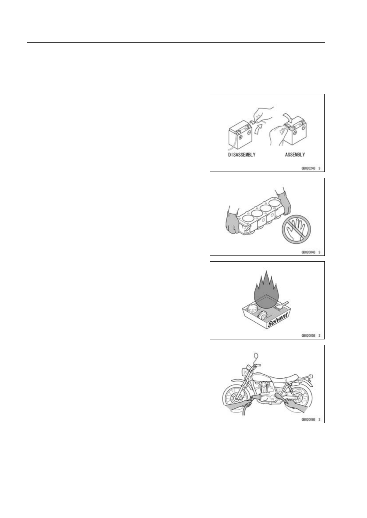
Battery Ground
Before completing any service on the motorcycle, disconnect the battery wires from the battery to prevent the engine
from accidentally turning over. Disconnect the ground wire
(−) first and then the positive (+). When completed with the
service, first connect the positive (+) wire to the positive (+)
terminal of the battery then the negative (−) wire to the negative terminal.
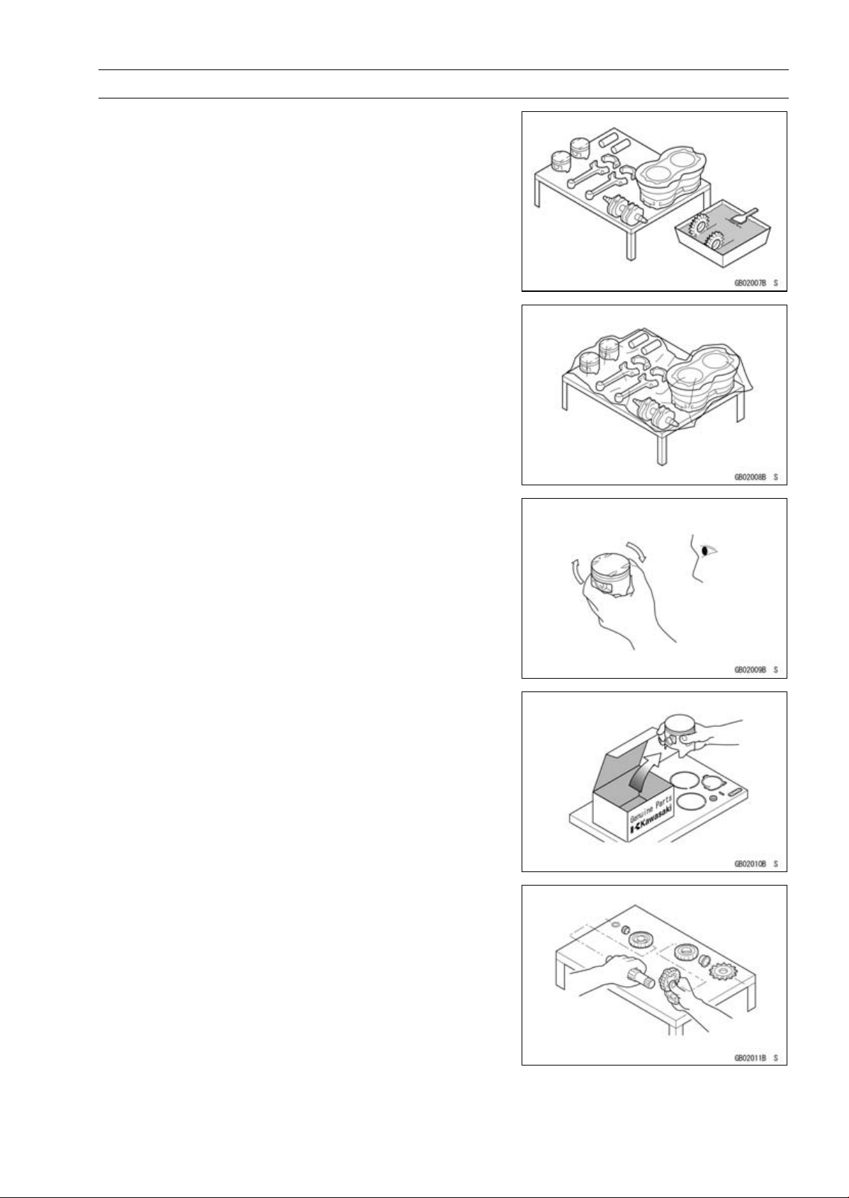
Edges of Parts
Lift large or heavy parts wearing gloves to prevent injury
from possible sharp edges on the parts.
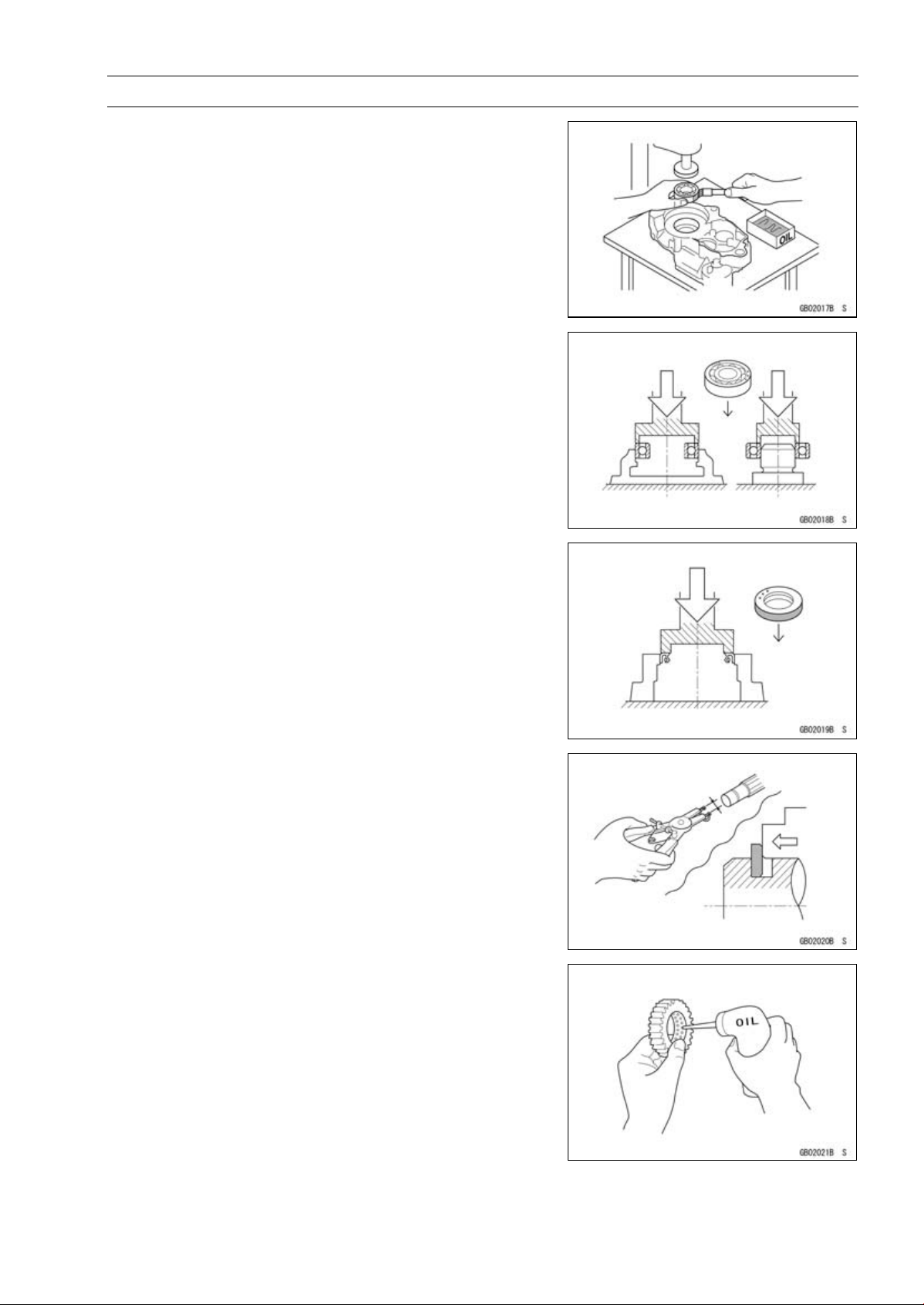
Solvent
Use a high flush point solvent w hen cleaning parts. High
flush point solvent should be used according to directions
of the solvent manufacturer.
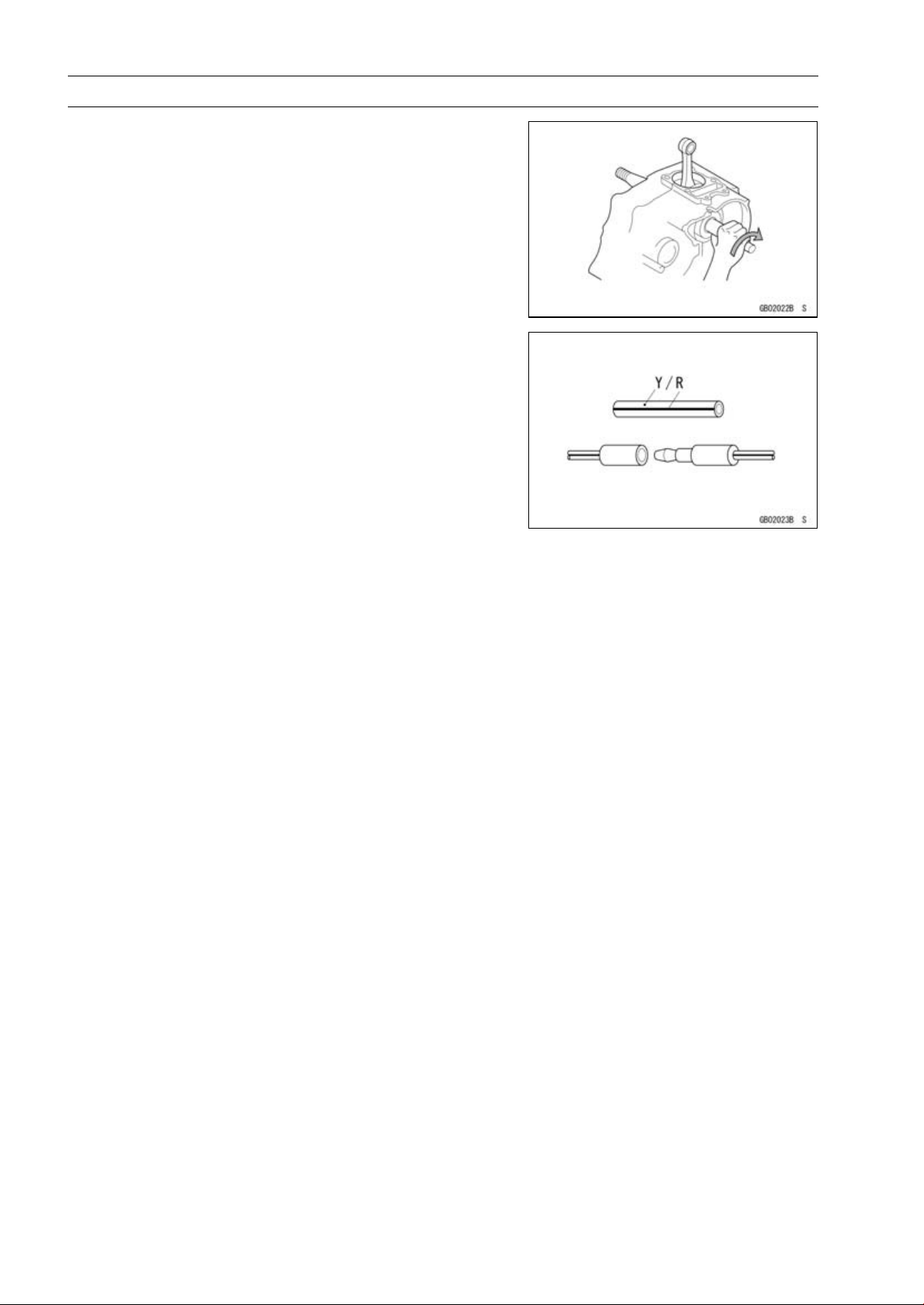
Cleaning vehicle before disassembly
Clean the vehicle thoroughly before disassembly. Dirt or
other foreign materials entering into sealed areas during vehicle disassembly can cause excessive wear and decrease
performance of the vehicle.
Before Servicing
Arrangement and Cleaning of Removed Parts
Disassembled parts are easy to confuse. Arrange the
parts according to the order the parts were disassembled
and clean the parts in order prior to assembly.
Storage of Removed Parts
After all the parts including subassembly parts have been
cleaned, store the parts in a clean area. Put a clean cloth
or plastic sheet over the parts to protect from any foreign
materials that may collect before re-assembly.
GENERAL INFORMATION 1-3
Inspection
Reuse of worn or damaged parts may lead to serious accident. Visually inspect removed parts for corrosion, discoloration, or other damage. Refer to the appropriate sections
of this manual for service limits on individual parts. Replace
the parts if any damage has been found or if the part is beyond its service limit.
Replacement Parts
Replacement Parts must be KAWASAKI genuine or recommended by K AWASAKI. Gaskets, O rings, Oil seals,
Grease seals, circlips or cotter pins must be replaced with
new ones whenever disassembled.
Assembly Order
In most cases assembly order is the reverse of disassembly, however, if assembly order is provided in this Service
Manual, follow the procedures given.

1-4 GENERAL INFORMATION
Before Servicing
Tightening Sequence
Bolts, nuts, or screws must be tightened according to the
specified sequence to prevent case warpage or deformation
which can lead to malfunction. If the specified tightening
sequence is not indicated, tighten the fasteners alternating
diagonally.
Tightening Torque
Incorrect torque applied to a bolt, nut, or screw may
lead to serious damage. Tighten fasteners to the specified
torque using a good quality torque wrench. Often, the
tightening sequence is followed twice-initial tightening and
final tightening with torque wrench.
Force
Use common sense during disassembly and assembly,
excessive force can cause expensive or hard to repair damage. When necessary, remove screws that have a non
-permanent locking agent applied using an impact driver.
Use a plastic-faced mallet whenever tapping is necessary.
Gasket, Or ing
Hardening, shrinkage, or damage of both gaskets
and O-rings after disassembly can reduce sealing performance. Remove old gaskets and clean the sealing
surfaces thoroughly so that no gasket material or other
material remains. Install new gaskets and replace used
O-rings when re-assembling
Liquid Gasket, Locking Agent
For applications that require Liquid Gasket or a Locking
agent, clean the surfaces so that no oil residue remains before applying liquid gasket or locking agent. Do not apply
them excessively. Excessive application can clog oil passages and cause serious damage.
Before Servicing
Press
For items such as bearings or oil seals that must be
pressed into place, apply small amount of oil to the contact area. Be sure to maintain proper alignment and use
smooth movements when installing.
Ball Bearing and Needle Bearing
Do not remove pressed ball or needle unless removal is
absolutely necessary. Replace with new ones whenever
removed. Press bearings with the manufacturer and size
marks facing out. Press the bearing into place by putting
pressure on the correct bearing race as shown.
Pressing the incorrect race can cause pressure between
the inner and outer race and result in bearing damage.
GENERAL INFORMATION 1-5
Oil Seal, Grease Seal
Do not remove pressed oil or grease seals unless r emoval
is necessary. Replace with new ones whenever removed.
Press new oil seals with manufacture and size marks facing
out. Make sure the seal is aligned properly when installing.
Circlips, Cotter Pins
Replace circlips or cotter pins that were removed with new
ones. Install the circlip with its sharp edge facing outward
and its chamfered side facing inward to prevent the clip from
being pushed out of its groove when loaded. Take care
not to open the clip excessively when installing to prevent
deformation.
Lubrication
It is important to lubricate rotating or sliding parts during
assembly to minimize wear during initial operation. Lubrication points are called out throughout this manual, apply
the specific oil or grease as specified.
1-6 GENERAL INFORMATION
Before Servicing
Direction of Engine Rotation
When rotating the crankshaft by hand, the free play
amount of rotating direction will affect the adjustment. Rotate the crankshaft to positive direction (clockwise viewed
from right side).
Electrical Wires
A two-color wire is identified first by the primary color and
then the stripe color. Unless instructed otherwise, electrical
wires must be connected to those of the same color.

Model Identification
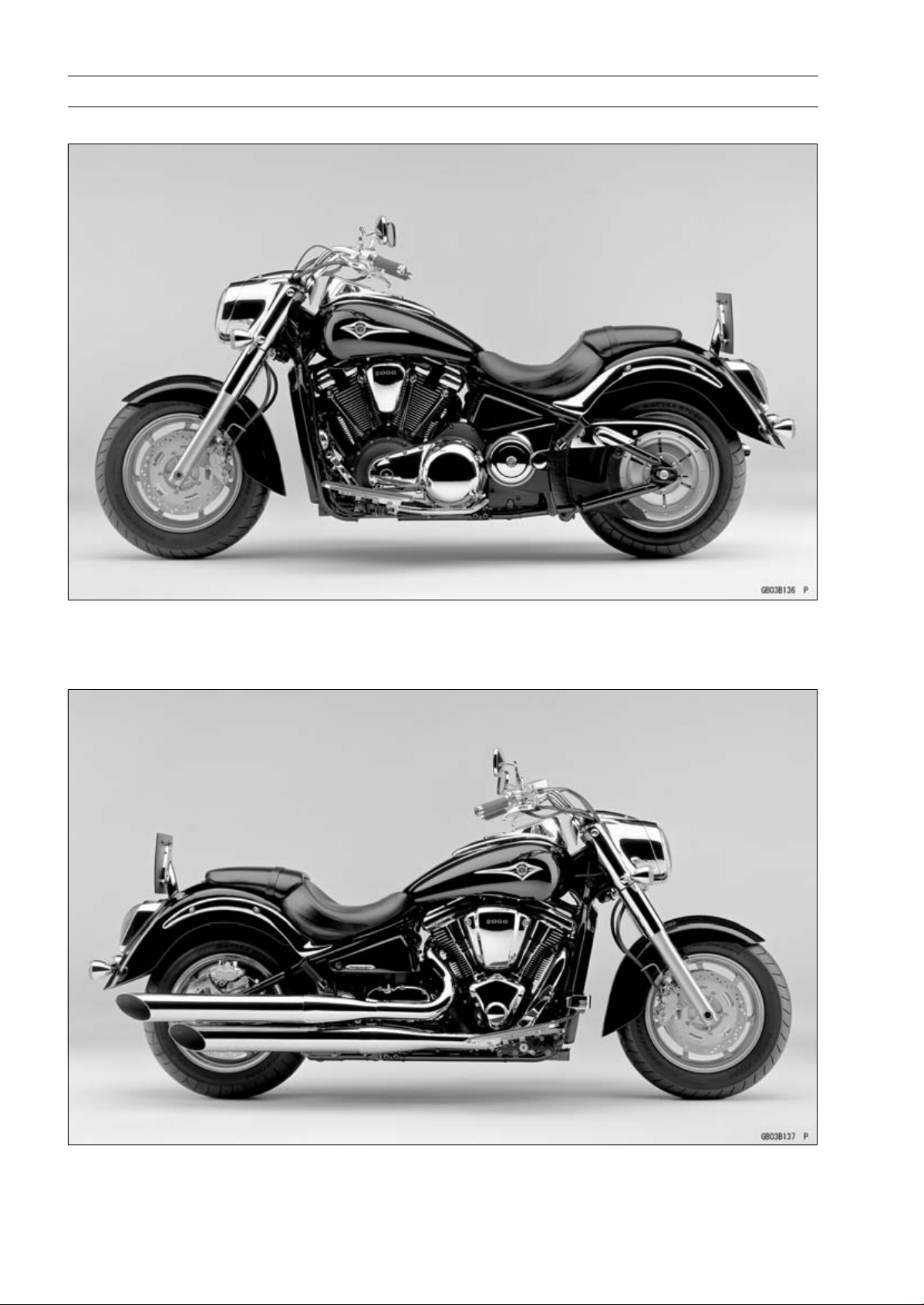
VN2000-A1 (US, and Canada) Left Side View:
GENERAL INFORMATION 1-7
VN2000-A1 (US, and Canada) Right Side View:
1-8 GENERAL INFORMATION
Model Identification
VN2000-A1 (Europe) Left Side View:
VN2000-A1 (Europe) Right Side View:

GENERAL INFORMATION 1-9
General Specifications
Items VN2000-A1
Dimensions:
Overall length 2 535 mm (99.80 in.)
Overall width 1 025 mm (40.35 in.), (AU) 985 mm (38.8 in.)
Overall height 1 155 mm (45.47 in.)
Wheelbase 1 735 mm (68.31 in.)
Road clearance
Seat height 680 mm (26.8 in.)
Dry mass
Curb mass: Front 176 kg (388 lb)
Rear 195 kg (429 lb)
Fuel tank capacity 21 L (5.5 US gal)
Fuel Unleaded and high-octane gasoline
Performance:
Minimum turning radius 3.2 m (10.5 ft)
Engine:
Type 4-stroke, OHV, V2-cylinder
Cooling system Liquid-cooled
Bore and stroke 103 × 123.2 mm (4.06 × 4.850 in.)
Displacement
Compression ratio 9.5 : 1
Maximum horsepower 76 kW (103 PS) @4 800 r/min (rpm), (CA) (CAL) (US) –
Maximum torque 177 N·m (18.05 kgf·m, 130.6 ft·lb) @3 200 r/min (rpm),
Carburetion system DFI (Digital Fuel Injection) System
Starting system Electric starter
Ignition system
Timing advance Electronically advanced (digital)
Ignition timing Front From 13° BTDC @900 r/min (rpm) ~ 51° BTDC
Rear From 15° BTDC @900 r/min (rpm) ~ 51° BTDC
Spark plugs NGK IZFR6F-11
Cylinder numbering method Front to Rear, 1-2
Firing order 1-2
V alve timing:
Inlet
Exhaust Open 69° BBDC
Lubrication system Forced lubrication (semi-dry sump)
Engine oil: Type
Open
Close 69° ABDC
Duration
Close 39° ATDC
Duration 288°
Viscosity SAE10W-40
Capacity
135 mm (5.32 in.)
340 kg (750 lb)
(see VN2000-A1 Owner’s Manual)
2 053 mL (125.3 cu in.)
(CA) (CAL) (US) –
Battery and coil (transistorized)
@4 000 r/min (rpm)
@4 000 r/min (rpm)
39° BTDC
288°
API SE, SF or SG class
API SH or SJ class with JASO MA
5.5 L (5.8 US qt, when engine is completely disassembled
and dry)

1-10 GENERAL INFORMATION
General Specifications
Items VN2000-A1
Drive Train:
Primary reduction system:
Type Chain
Reduction ratio
Clutch type Wet multi disc
Transmission:
Type 5-speed, constant mesh, return shift
Gear ratios: 1st 2.550 (51/20)
2nd
3rd 1.218 (39/32)
4th
5th 0.729 (27/37)
Final drive system:
Type Belt
Reduction ratio 2.744 (50/40 × 72/32), (EU) 2.455 (48/44 × 72/32)
Overall drive ratio 3.003 @ Top gear, (EU) 2.687 @ Top gear
Frame:
Type Tubular, double cradle
Caster (rake angel) 32°
Trail 182 mm (7.17 in.)
Front tire: Type Tubeless
Size 150/80 - R16MC 71V
Rear tire: Type Tubeless
Size 200/60 - R16MC 79V
Front suspension: Type Telescopic fork
Wheel travel 150 mm (5.91 in.)
Rear suspension: Type Swingarm with mono-shock (non-link type)
Wheel travel
Brake Type: Front Dual disc
Rear
Electrical Equipment:
Battery Capacity 12 V 18 Ah
Headlight: Type Semi-sealed beam
Bulb 12 V 65 W (quartz-halogen)
Tail/brake light 12 V 5/21 W
Alternator: Type
Rated output 38A × 14 V @5 000 r/min (rpm)
Specifications are subject to change without notice, and may not apply to every country.
AU: Australia
CAL: California
CA: Canada
US: United States of America
EU: Europe
1.500 (48/32)
1.629 (44/27)
0.939 (31/33)
100 mm (3.94 in.)
Single disc
12 V 55 W (quartz-halogen)
Three-phase AC
Technical Information – Oxygen Sensor
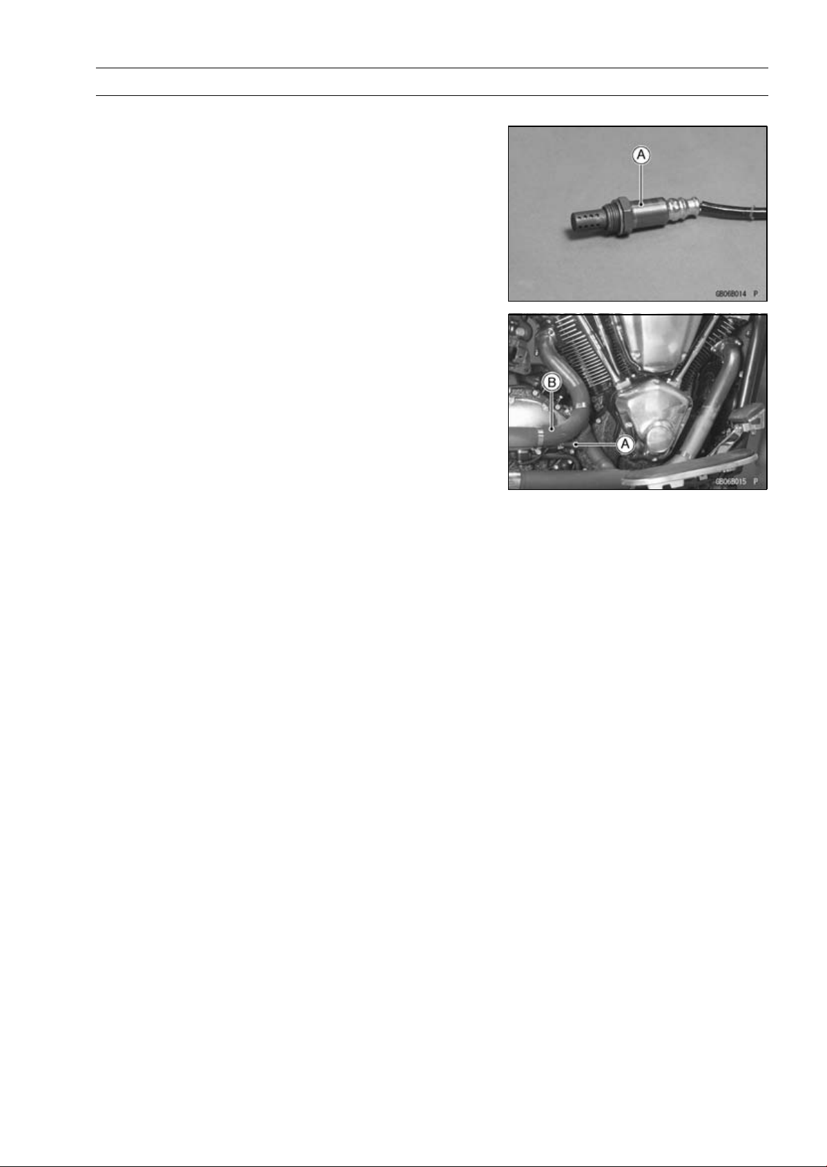
Overview
Kawasaki has adopted an oxygen sensor [A] for the European and California models in addition to the secondary air
injection system and honeycomb catalyst. This helps Kasawaki keep the motorcycle with cleaner exhaust gas and
cope with the emission regulations.
The oxygen sensor [A] is mounted above the exhaust
manifold [B], w hereas the honeycomb catalyst is located
inside the silencer in the downstream of the exhaust gas.
GENERAL INFORMATION 1-11
The oxygen sensor uses the substance called zirconia
(ZrO
2). The electromotive force varies depending on the
density of the oxygen. The sensor measures the oxygen
density of the exhaust gas to detect whether the air/fuel
mixture is lean or rich in relation to the optimum air/fuel
mixture.
When the ECU is in the oxygen sensor feedback mode, it
controls combustion by making the fuel injection amount of
the injector rich or lean through the signal from the sensor.
1-12 GENERAL INFORMATION
Technical Information – Oxygen Sensor
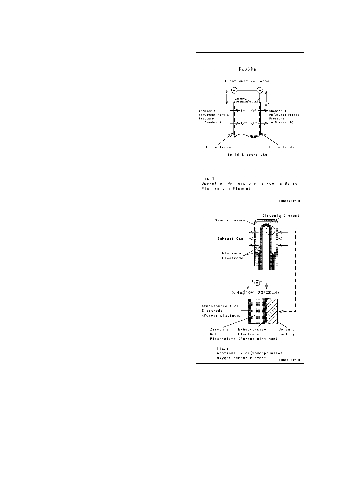
Construction and Operation
The oxygen sensor uses, a solid electrolyte called zirco-
nia.
An electrolyte is a substance that has positive (+) and
negative (−) ions and can move freely i n a liquid.
For explanation purposes, picture a solid electrolyte plate
as a wall and chambers A and B are divided by this wall. If
both sides of the wall have platinum electrodes with holes,
the difference in oxygen density (weight) between chambers A and B will move the oxygen from the chamber of
higher oxygen density to the chamber of lower oxygen density until the two chambers are about equal in density. What
actually moves are the oxygen ions (−) through the wall of
the solid electrolyte.
The higher-density-side chamber will receive the “Pt”
electrode surface with holes on the solid electrolyte wall
and will become minus the oxygen ions (O
the O
2− ions reach the “Pt” electrode of the opposite side.
Since the result of this O
“e
−” (just like “cells” w ork in a battery), voltage will be built
2− move also brings movement of
within the sensor.
2−). At this point,
The (conceptual) sectional view of the actual element in
the oxygen sensor is shown. The sensor is exposed to exhaust gas. The shape of the sensor is tubular since the atmospheric side and exhaust gas side are parted by the wall.
That means that the inside of this tubular solid electrolyte is
the atmosphere side (higher oxygen density), and the outside of the tube faces the exhaust gas. The outside surface,
which is in the stream of exhaust gases, has a coated layer
of porous ceramic. Voltage is generated and can be measured because of the difference in oxygen density (positive
and negative ions).
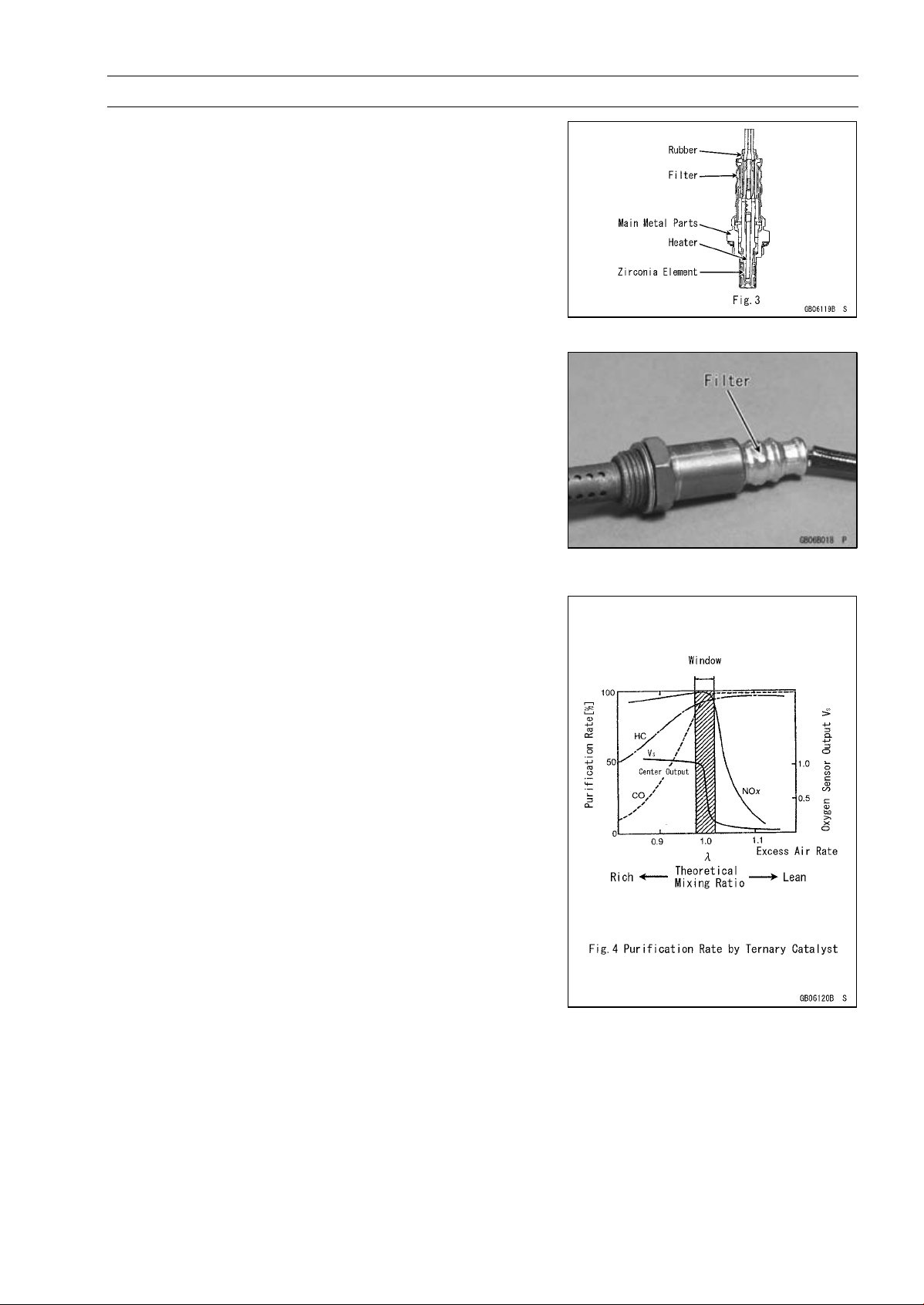
Technical Information – Oxygen Sensor
The sensor, uses the fresh air as the oxygen reference,
and consists of a passageway to lead the fresh air inside
the tubular element. Installed in this passageway is, a air
permeable filter that allows the fresh air to pass through,
but won’t allow moisture through. This keeps the sensor in
touch with the atmosphere.
At a normal temperature, Zirconia (solid electrolyte) is
an insulator and not able to sense the gases. Since the
exhaust gas temperature does not become hot instantly,
it takes sometime before the sensor starts to work. To
solve the problem of the slow temperature increase of exhaust gases (which warms the electrolyte element), a built
-in heater located i nside the tubular element increases the
temperature of the sensor so it can operate at a low exhaust gas temperature. Furthermore this built-in heater
helps keep the sensor at a constant temperature.
GENERAL INFORMATION 1-13
Air/Fuel Ratio Control By Oxygen Sensor
”λ=1” indicates the optimum air/fuel ratio point, meaning
the air/fuel ratio at which optimum (complete) combustion
can be obtained. In the proximity of this mixture, the purification efficiency of the catalyst will be maximized.
The purification ratio of the three kinds of gas, HC (hydrocarbons), CO (carbon monoxide), Nox (nitrogen oxides)
using the ternary (three) catalyst is shown in Fig. 4.
The best purification rate is at the zone where the oxygen sensor ’s signal shows the sharp changes. This zone is
called the “window” and if the oxygen sensor signal moves
back and forth between the rich side (fuel rich) and lean
side (fuel lean) from the oprimum mix ratio (but still within
the width of the window), it indicates that the exhaust gas
is in a good purification rate zone.
1-14 GENERAL INFORMATION
Technical Information – Oxygen Sensor
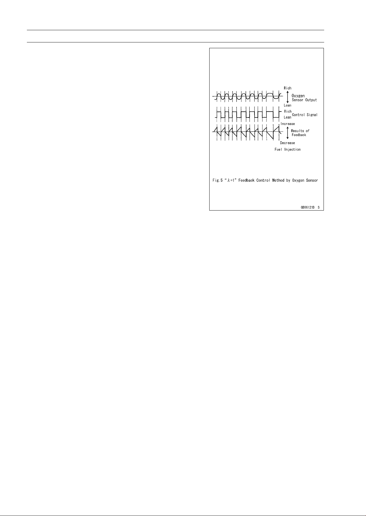
Figure 5 shows how the sensor operates the controlling
factors.
There is a sharp voltage drop of about 1V (in reality, about
0.9 V) the sensor uses for control (a standard reference).
By utilizing this voltage and using 0.45 V as the reference
line, an output larger than the line indicates that exhaust gas
is in the lean zone. So, when the system senses a “rich”
condition through the sensor’s output voltage, it controls
the fuel injection amount to make the fuel gradually leaner.
When it reaches a leaner point, the sensor voltage signal
drops sharply at the proximity λ=1 and goes below 0.45V.
The system, at this level, senses that it has changed to
“lean” and reverse the voltage signal to make the fuel richer.
It then controls the fuel injection amount to make the fuel
gradually richer. When it drops to a richer point, the signal
drops sharply at the proximity λ=1 and goes over 0.45V. The
system, at this level, senses that it has changed to “rich”
and reverse the signal to make the fuel leaner. By having
the signal repeat back and forth between the rich and lean
sides, it can constantly stay within the window of the good
purification rates. Thereby the oxygen sensor, works as a
combustion control sensor for the optimum air/fuel ratio.

Technical Information – Oxygen Sensor
Maintenance
1) Periodic Inspections
Periodic inspections or special maintenance is not required for the sensor.
2) Oxygen Sensor Removal and Installation
Handle the oxygen sensor with care. Be careful not
to damage sensor wires. Do not service the oxygen
sensor while it is hot and not use an inpact wrench
while removing or installing the oxygen sensor.
Avoid the fouling (damaging) of the sensing part of the
sensor with foreign substances such as coolant, battery
fluid, anti-corrosion fluid, and brake fluid.
Stop using the sensor if it is fouled with these substances.
Also stop using the sensor if the head part of the sensor
(exposed to the atmosphere) is fouled. Since the sensor has a filter that allows air to escape but stop water,
fouling of the sensor head may clog this filter.
Being subjected to a flame is also unacceptable for the
sensor with the same reason as above.
3) Condition of the Sensor
Perform resistance measurements and visually check
for scars, bends, and clogging of the sensor filter.
4) If trouble with the sensor occurs, one of the following
service codes will be displayed. Accordingly, follow the
related procedures in the Service Manual for necessary
maintenance.
GENERAL INFORMATION 1-15
Service Code Outline of trouble
33 Oxygen sensor is not activated
67 Heater trouble due to wiring short or open
94
Oxygen sensor output voltage is incorrect

1-16 GENERAL INFORMATION
Technical Information – Electric Solenoid Operated Decompressor
An automatic decompressor (Automatic Compression
Reliese) system is installed to the right side of the engine.
This decompressor is activated by an electric solenoid to
make starting engine easy. When the ignition is switched
on and the starter button depressed, the solenoid pulls a
fulcrum-mounted link that depresses push rods in each
camshaft.
The push rods activate the decompression mechanism
to partially open the exhaust valves as the piston nears top
dead center, releasing some of compression that can cause
resistance during starting.
Releasing the starter button de-activates the solenoid and
a spring returns the push rods to their normal operating position.
1. Decompression Solenoid
2. Decompression Lever
3. Decompression Push Rod
4. Holder
5. Decompression Shaft
6. Spring
7. Exhaust Cam
8. Push Rod
GENERAL INFORMATION 1-17
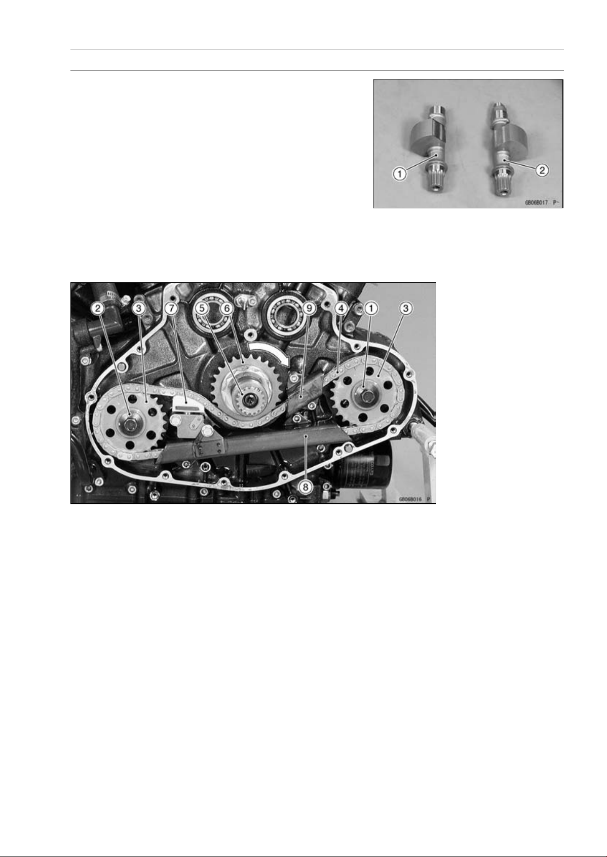
Technical Information – Dual Balancer Shaft System
Dual balancers harmonize primary balance and reduce
vibration.
The VN2000-A1 engine applied two balancer shafts, one
[1] is located in front of the front cylinder and another one
[2] is behind the rear cylinder.
Each balancer shaft is driven by the chain which driven to
the counterclockwise by crankshaft sprocket that rotate to
the clockwise viewed from the righr side.
The hydraulically operated chain tensioner is located between crankshaft and rear balancer shaft.
The hydraulic chain tensioner is supplied the oil pressure
from lubrication feed pump.
Two chain guides applied, one is between the crankshaft
and front balancer shaft and another is under the crankshaft
sprocket.
1. Front Balancer Shaft
2. Rear Balancer Shaft
3. Front and Rear Balancer
Sprocket
4. Balancer Drive Chain
5. Crankshaft
6. Balancer Drive Sprocket
7. Hydraulic Chain Tensioner
8. Chain Guide (under
Crankshaft)
9. Chain Guide (between
Crankshaft and Front
Balancer Shaft)

1-18 GENERAL INFORMATION
Technical Information – Dual Balancer Shaft System
1. Front Balancer Shaft
2. Rear Balancer Shaft
3. Front and Rear Balancer
Sprocket
4. Balancer Drive Chain
5. Crankshaft
6. Balancer Drive Sprocket
7. Hydraulic Chain Tensioner
8. Chain Guide (between
Crankshaft and Front
Balancer Shaft)
9. Chain Guide (under
Crankshaft)
10. Front
11. Le f t

Unit Conversion Table
GENERAL INFORMATION 1-19
Prefixes for Units:
Prefix Symbol Power
mega M × 1 000 000
kilo k × 1 000
centi c ×0.01
milli m × 0.001
micro µ × 0.000001
Units of Mass:
kg ×2.205=lb
g × 0.03527 = oz
Units of Volume:
L × 0.2642 = gal (US)
L × 0.2200 = gal (imp)
L×1.057=
L × 0.8799 = qt ( imp)
L×2.113=
L × 1.816 = pint (imp)
mL × 0.03381 = oz (US)
mL × 0.02816 = oz (imp)
mL × 0.06102 = cu in.
qt (US)
pint (US)
Units of Length:
km × 0.6214 = mile
m × 3.281 = ft
mm × 0.03937 = in.
Units of Torque:
N·m × 0.1020 = kgf·m
N·m × 0.7376 = ft·lb
N·m × 8.851 = in·lb
kgf·m × 9.807 = N·m
kgf·m
kgf·m × 86.80 = in·lb
× 7.233 =
ft·lb
Units of Pressure:
kPa × 0.01020 =
kPa × 0.1450 = psi
kPa × 0.7501 = cm Hg
kgf/cm² × 98.07 = kPa
kgf/cm² × 14.22 = psi
cm Hg × 1.333 = kPa
kgf/cm²
Units of Speed:
km/h × 0.6214 = mph
Units of Force:
N × 0.1020 =
N × 0.2248 = lb
kg ×9.807=N
kg ×2.205=lb
Units of Temperature:
kgf
Units of Power:
kW × 1.360 = PS
kW × 1.341 = HP
PS × 0.7355 = kW
PS
× 0.9863 = HP
 Loading...