


 Loading...
Ninja ZX-6R
2008 Ninja ZX-6R
Racing Kit Manual
This manual contains only the information of the racing kit parts. Refer to the base manual listed below for information of the original model.
Base Manual |
Part Number |
|
Ninja ZX-6R |
99924-1382-02 |
|
Motorcycle Service Manual |
||
|
© 2008 Kawasaki Heavy Industries, Ltd. |
First Edition (1): Jan. 25, 2008 |

Congratulation on your purchase of racing kit parts for the 2008 Ninja ZX-6R.
IMPORTANT
This manual provides how to install racing kit parts for the 2008 Ninja ZX-6R and how to tune up basically.
As for the basic knowledge, refer to the base Service Manual for the Ninja ZX-6R (P/No. 99924-1382-02).
When you participate in a race, it is necessary to modify the machine for the regulation. So we want you to ask for the tuning up shop.
 WARNING
AFTER ANY MODIFICATION TO TUNE THE VEHICLE TO A COMPETITION MACHINE, IT SHOULD NOT BE USED ON PUBLIC STREETS, ROADS OR HIGHWAYS. THE USE OF THIS VEHICLE SHOULD BE LIMITED TO PARTICIPATION IN SANCTIONED
COMPETITION EVENTS UPON A CLOSED COURSE.
CAUTION
When operating the engine, be careful not to trouble persons with noise. Do not turn the engine with loud engine and exhaust noise.
DISCLAIMER OF WARRANTY
ON OPTIONAL TUNING PARTS FOR RACING ARE NO WARRANTIES EXPRESSED OR IMPLIED.
BASIC WORKS IN INSTALLING KIT PARTS
We are going to make up the original Ninja ZX-6R for the racing machine. We recommend that the rider himself should do the basic works, removing parts or installing parts etc., given advices by the tuning shop. In a race, although trouble will be apt to happen, if you participate in basic works, you can discriminate cause of trouble, so you can return the race soon.
But concerning difficult technical works, you should as tuning shop.
1
Dummy page
2
Table of Contents |
|
General Specifications ...................................................................................................... |
4 |
Racing Kit Service Data .................................................................................................... |
6 |
Periodic Maintenance Chart ............................................................................................. |
7 |
Preparation......................................................................................................................... |
9 |
Before Installing .................................................................................................................................... |
9 |
Racing Kit Parts................................................................................................................. |
9 |
Engine Parts Installation................................................................................................... |
9 |
Air Intake Parts ..................................................................................................................................... |
9 |
Cylinder Head ..................................................................................................................................... |
11 |
Camshaft Chain Tensioner.................................................................................................................. |
12 |
Camshafts, Sprockets......................................................................................................................... |
13 |
Valve Springs...................................................................................................................................... |
14 |
Cylinder Compression......................................................................................................................... |
14 |
Crankshaft Main Journal and Connecting Rod Big End Bushings ...................................................... |
16 |
Connecting Rod Bolts ......................................................................................................................... |
19 |
Clutch Adjustment (Back-Torque Limiter Setting)................................................................................ |
20 |
Transmission....................................................................................................................................... |
24 |
Transmission Shimming...................................................................................................................... |
24 |
Generator (Option).............................................................................................................................. |
25 |
Generator Cover (Option) ................................................................................................................... |
25 |
Cover Gaskets .................................................................................................................................... |
25 |
Ducts (Air Funnels) ............................................................................................................................. |
25 |
Muffler................................................................................................................................................. |
26 |
Water Temperature Sensor................................................................................................................. |
26 |
Radiator (Kit)....................................................................................................................................... |
26 |
Oil Catch Tank Installation .................................................................................................................. |
30 |
Frame Parts Installation .................................................................................................. |
33 |
Throttle Parts (Kit)............................................................................................................................... |
33 |
Brake Pads (Kit).................................................................................................................................. |
34 |
Steering Damper (Kit) ......................................................................................................................... |
34 |
Seat Height Adjustment ...................................................................................................................... |
35 |
Front Fork Springs (Kit)....................................................................................................................... |
37 |
Electric Parts Installation................................................................................................ |
39 |
Battery ................................................................................................................................................ |
39 |
Main Harness and Sub Harness (Kit) ................................................................................................. |
39 |
Meter (Kit) Installation ......................................................................................................................... |
40 |
Wiring Routing .................................................................................................................................... |
42 |
Wiring Diagram (with Kit Meter) ..................................................................................... |
44 |
Wiring Diagram (with Original Meter Assembly)........................................................... |
46 |
3

General Specifications
Item |
2008 Ninja ZX-6R Racing |
Engine: |
|
Ignition timing |
12.5°BTDC @1 300 r/min (rpm) |
Fuel (Recommended) |
Racing gasoline |
Engine oil (Recommended): |
Racing oil |
Level |
Between upper and lower levels of oil level gauge. |
Drive Train: |
|
Primary drive reduction ratio |
1.900 (76/40) |
Transmission Gear Table
|
|
STD |
Type B |
Type C |
Type D |
|
|
|
(Type A) |
||||
|
|
|
|
|
||
|
In |
13127-0044 |
13127-0055 |
13127-0055 |
|
|
1st |
Out |
13262-0507 |
13262-0526 |
13262-0535 |
|
|
Teeth (Out/In) |
38/14 |
37/14 |
36/14 |
|
||
|
|
|||||
|
Gear Ratio |
2.714 |
2.643 |
2.571 |
|
|
|
In |
13262-0372 |
13262-0527 |
13262-0536 |
13262-0677 |
|
2nd |
Out |
13262-0508 |
13262-0528 |
13262-0537 |
13262-0678 |
|
Teeth (Out/In) |
33/15 |
39/18 |
34/16 |
36/16 |
||
|
||||||
|
Gear Ratio |
2.200 |
2.167 |
2.125 |
2.25 |
|
|
In |
See Gear |
See Gear |
|
|
|
|
Selection |
Selection |
|
|
||
|
|
|
|
|||
3rd |
Out |
13262-0509 |
13262-0683 |
|
|
|
|
Teeth (Out/In) |
37/20 |
32/17 |
|
|
|
|
Gear Ratio |
1.850 |
1.882 |
|
|
|
|
In |
See Gear |
See Gear |
See Gear |
See Gear |
|
|
Selection |
Selection |
Selection |
Selection |
||
|
|
|||||
4th |
Out |
13262-0510 |
13262-0530 |
13262-0684 |
13262-0685 |
|
|
Teeth (Out/In) |
32/20 |
33/20 |
39/23 |
30/19 |
|
|
Gear Ratio |
1.600 |
1.650 |
1.696 |
1.579 |
|
|
In |
13262-0374 |
13262-0531 |
13262-0538 |
13262-0686 |
|
5th |
Out |
13262-0380 |
13262-0532 |
13262-0539 |
13262-0687 |
|
Teeth (Out/In) |
27/19 |
30/20 |
32/22 |
32/23 |
||
|
||||||
|
Gear Ratio |
1.421 |
1.500 |
1.455 |
1.391 |
|
|
In |
13262-0375 |
13262-0533 |
13262-0540 |
13262-0688 |
|
6th |
Out |
13262-0582 |
13262-0534 |
13262-0541 |
13262-0689 |
|
Teeth (Out/In) |
26/20 |
32/23 |
35/26 |
29/23 |
||
|
||||||
|
Gear Ratio |
1.300 |
1.391 |
1.346 |
1.261 |
4
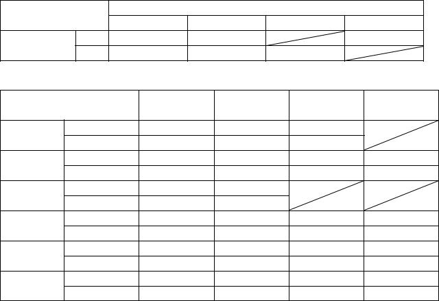
Input 3rd/4th Gear Selection Table
4th Gear
|
|
A |
B |
C |
D |
3rd Gear |
A |
13262-0506 |
13262-0529 |
|
13262-0679 |
B |
13262-0680 |
13262-0681 |
13262-0682 |
|
|
|
|
Gear Identification Slit Number Table
|
|
STD |
Type B |
Type C |
Type D |
|
|
|
(Type A) |
||||
|
|
|
|
|
||
1st |
In |
0 |
1 |
1 |
|
|
Out |
0 |
1 |
2 |
|
||
|
|
|||||
2nd |
In |
0 |
1 |
2 |
3 |
|
Out |
0 |
1 |
2 |
3 |
||
|
||||||
3rd |
In |
0 |
1 |
|
|
|
Out |
0 |
1 |
|
|
||
|
|
|
||||
4th |
In |
0 |
1 |
2 |
3 |
|
Out |
0 |
1 |
2 |
3 |
||
|
||||||
5th |
In |
0 |
1 |
2 |
3 |
|
Out |
0 |
1 |
2 |
3 |
||
|
||||||
6th |
In |
0 |
1 |
2 |
3 |
|
Out |
0 |
1 |
2 |
3 |
||
|
5

Racing Kit Service Data
Item |
Standard |
Cylinder Head, Valves: |
|
Duration: |
|
Intake |
288° |
Exhaust |
266° |
Camshaft timing (cam lift center): |
|
Intake |
105° (ATDC) |
Exhaust |
110° (BTDC) |
Valve clearance: |
|
Intake |
0.16 mm |
Exhaust |
0.28 mm |
Valve to piston clearance: |
|
Intake |
0.80 mm (Minimum) @12°ATDC |
Exhaust |
1.40 mm (Minimum) @11°BTDC |
Ignition System: |
|
Spark plugs |
NGK R0045Q-10, R0373A-10 |
Spark plug tightening torque |
13 N·m (1.3 kgf·m, 113 in·lb) |
These values show the specifications when standard cylinder head and gasket are used. When the clearance between the valve and the piston head is smaller than the minimum specific values, turn the installed position of the camshaft sprocket on the camshaft and
change the camshaft timing.
6

Periodic Maintenance Chart
The scheduled maintenance must be done in accordance with this chart to keep the motorcycle in good running condition.
FREQENCY |
Each |
Every |
Every |
Every |
As |
|
Race |
3 races |
5 races |
10 races |
|
OPERATION |
Required |
||||
(300 km) |
(1 000 km) |
(1 500 km) |
(3 000 km) |
|
|
Engine |
|
|
|
|
|
Clutch plate - - check* |
● |
|
|
|
|
Throttle grip play - - check* |
● |
|
|
|
|
Spark plug - - clean/gap* |
● |
|
|
|
|
Engine oil - - change |
● |
|
|
|
|
Oil filter - - replace |
● |
|
|
|
|
Valve lapping |
|
|
● |
|
|
Cylinder head/valve - - decarbonization |
|
|
● |
|
|
Cylinder - - check* |
|
|
● |
|
|
Piston/cylinder clearance - - check* |
|
|
● |
|
|
Piston, Piston ring, Piston pin - - replace |
|
|
● |
|
|
Crankshaft main bearing - - check* |
|
|
|
● |
|
Connecting rod big end bearing - - check* |
|
|
|
● |
|
Transmission gear, bearing - - check* |
|
|
|
● |
|
Engine sprocket - - check* |
● |
|
|
|
|
Coolant - - change |
|
|
|
|
● |
Radiator hoses, connections - - check* |
● |
|
|
|
|
Frame |
|
|
|
|
|
Brake operation - - check* |
● |
|
|
|
|
Brake pad wear - - check* |
● |
|
|
|
|
Brake fluid level - - check* |
● |
|
|
|
|
Brake fluid - - change* |
|
|
|
|
year |
Brake master cylinder cup and dust seal - - replace |
|
|
|
|
year |
Brake caliper piston seal and dust seal - - replace |
|
|
|
|
year |
Brake hose - - replace |
|
|
|
|
2 years |
Drive chain - - adjust |
● |
|
|
|
|
Drive chain - - lubricate |
● |
|
|
|
|
Drive chain wear - - check* |
● |
|
|
|
|
Drive chain guide - - replace |
|
|
If damaged |
|
|
Front fork - - clean/check* |
● |
|
|
|
|
Front fork oil - - change |
First change after 2 races, then every 5 races |
||||
Nut, bolt, and fastener tightness - - check* |
● |
|
|
|
|
Fuel system - - clean |
● |
|
|
|
|
Fuel hose, fuel filter - - replace |
|
|
|
|
● |
Steering play - - check* |
● |
|
|
|
|
Steering stem bearing - - grease |
|
|
● |
|
|
Rear sprocket - - replace |
|
|
|
|
● |
General lubrication of chassis - - perform |
● |
|
|
|
|
7
FREQENCY |
Each |
Every |
Every |
Every |
As |
|
Race |
3 races |
5 races |
10 races |
|
OPERATION |
Required |
||||
(300 km) |
(1 000 km) |
(1 500 km) |
(3 000 km) |
|
|
Wheel bearing (rear) - - grease |
|
|
|
● |
|
Swingarm pivot, uni-track linkage - - grease |
|
|
● |
|
|
Swingarm pivot, uni-track linkage - - check* |
|
|
● |
|
|
*: Replace, add, adjust, clean, or torque if necessary.
8
Preparation
Before Installing
Modify the parts based on your race regulation.
To avoid misuse keep the parts replaced with the kit parts separate.
When reusing parts, clean them and check them for damage or deterioration. Main Removal Parts:
Lights
Rear View Mirrors Side Stand
Starter Lockout Switch
Remove the side stand switch. When the optional main harness is not used, connect removing Black/Yellow and Green/White Leads directly.
Racing Kit Parts
Also, we have provided the spare parts, and other optional parts (engine, frame, and electric parts) for racing. So please order each parts referring to the “Racing Kit Parts List” in the back of this manual.
Engine Parts Installation
Air Intake Parts
Remove the wire net of Ram – Air duct intake to reduce the air flow resistance.
Remove the tank (16181-0011) to reduce the weight. Plug the holes firmly with a tape. The air pressure in the duct rises during high speed operation because the Ram Air System is used.
A.Wire Net (14037-0057)
B.Tank (16181-0011)
9

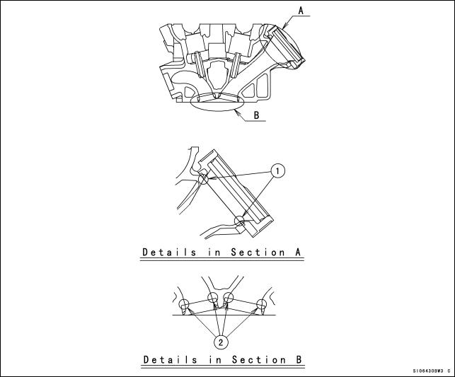
Remove the secondary valves of cylinder head and relational parts, then plug the each holes.
Remove the oil receiver and plug the hole.
Remove the air cleaner element or cut the cleaner element off remaining punched plate to reduce the air flow resistance.
1.Remove the parts.
2.Plug the holes.
3.Replace with plugs (92043-1506), and plug the holes.
10
Cylinder Head
Grind off the stepped portions of the ports and smooth the inside of ports to make intake/exhaust gas flow more smooth.
Grind off the stepped portion only at the mating surface between the carburetor holder and the intake port. Do not port it. To extend the intake port, air flow speed will be reduced and the engine performance at the high speed range may be down.
Mark the carburetor holders so that they can be installed in their original positions. Grind off and smooth the stepped portions at the mating surface between valve seat and
the port.
Smooth the inside of the intake port and exhaust port. Use the hand grinder.
Use #200 oil stone for eliminating any stepped portions.
Use #200 oil stone for smoothing and #300 oil stone for finishing.
NOTE
These procedures make air resistance less and intake/exhaust gas flow more smooth. However, much more effect can not be expected by excessive grinding and smoothing. It may be done to the extent of getting rid of uneven surfaces.
1.Stepped Portions of carburetor holder and cylinder head.
2.Stepped Portions of valve seat and cylinder head.
11

The combustion chambers are modified by cutting work but the edges shown must be hand finished for smooth corners (Round them to about R1).
Chamfer the machining edge of the cylinder head where the valve seat is installed, also smooth the dome of the combustion chamber with the valves installed. Excessive smoothing may reduce the cylinder compression.
XXX. Edges
NOTE
When grinding the cylinder head bottom surface or using thinner gaskets, adjust the valve timing to keep that the valve to piston clearance is not less than the minimum value (IN: 0.8 mm, EX: 1.4 mm).
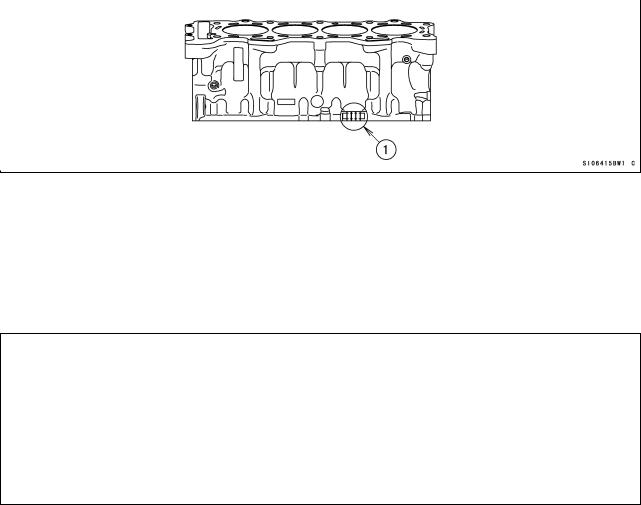
Camshaft Chain Tensioner
Replace the cam chain tensioner with the kit to gain the durability.
Apply the engine oil to the tensioner rod, O-ring and tensioner body, insert them into the tensioner body.
Check to see that the tensioner rod turns freely in the body, if not, polish the tensioner rod or fine the female threads in the body with a tap (Diameter × Pitch = 6 mm × 1.0 mm).
Install the tensioner on the cylinder block with the tensioner rod is fully pushed back. Turn the tensioner rod in with a screwdriver until it becomes hard to turn.
Turn the crankshaft clockwise forcing lightly to the tensioner rod with twisting force to take up any gap and tighten the locknut.
Tighten the rock nut after adjustment.
NOTE
Never forward the tensioner rod forcibly, this will increase mechanical loss of the tensioner and may damage to the chain guide.
The cam chain tensioner must be adjusted at every race.
12
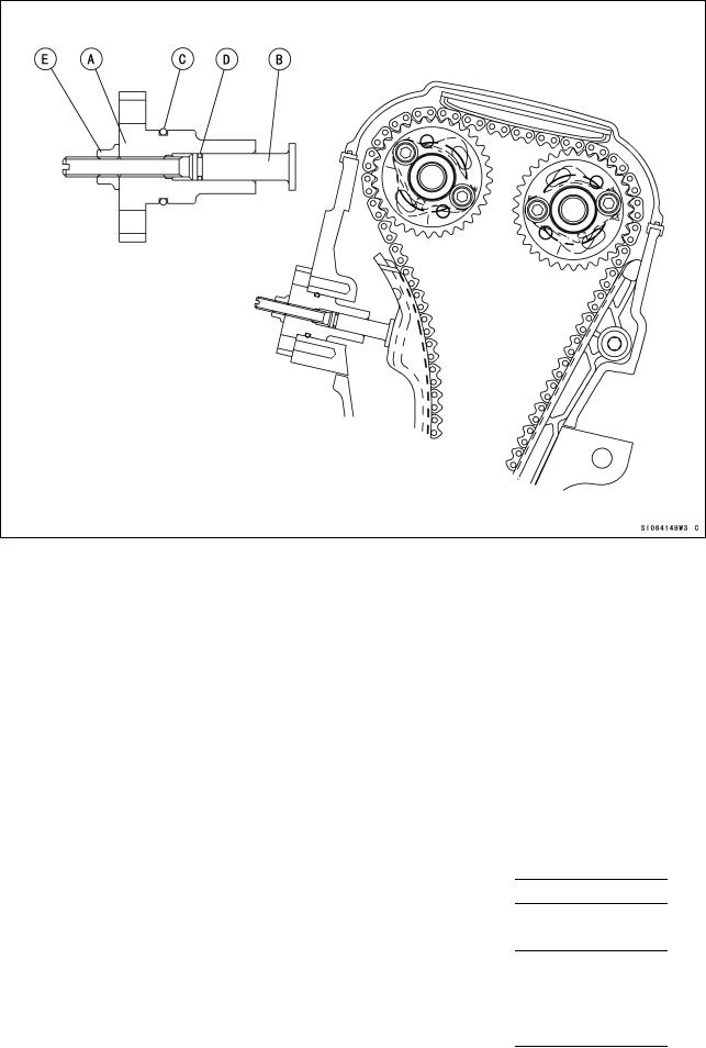
A.Tensioner
B.Tensioner Rod
C.O-ring
D.O-ring
E.Lock nut
Camshafts, Sprockets
Camshafts, Sprockets:
Adjust the valve clearance within the specified value, but more performance is expected when adjusted from middle value to upper limit between adjustable range.
Original |
|
|
Timing |
Cam Lift |
|
Valve Clearance |
||
Intake |
|
|
288° |
8.30 mm |
|
0.13 0.19 mm |
||
Exhaust |
|
|
266° |
7.50 mm |
|
0.24 0.31 mm |
||
|
|
|
|
|
|
|
||
Kit |
Timing |
|
|
Cam Lift |
|
Valve Clearance |
||
Intake |
308° |
|
|
8.30 mm |
|
0.13 0.19 mm |
||
49118-0110 |
|
(conformed to FIM regulation) |
|
|||||
|
|
|
|
|
||||
Exhaust |
274° |
|
|
7.30 mm |
|
0.24 0.31 mm |
||
49118-0111 |
|
(not conformed to FIM regulation) |
|
|||||
|
|
|
|
|
||||
Exhaust |
274° |
|
|
7.50 mm |
|
0.24 0.31 mm |
||
49118-0120 |
|
(conformed to FIM regulation) |
|
|||||
|
|
|
|
|
||||
|
|
|
|
|
13 |
|
|
|
If you don’t adjust the valve timing for racing, install the camshaft sprocket to the kit camshaft using the round bolt holes and adjust the cam chain timing according to the Ninja ZX-6R Service Manual. If you adjust the valve timing, install the sprocket to the camshaft between the adjustable range of the long bolt holes.
Tighten the camshaft sprocket bolts to 15 N·m (1.5 kgf·m, 11.0 ft·lb) of torque.
Valve Timing (when the round bolt holes are used)
Timing (cam lift center) |
Intake |
Exhaust |
Original |
105° |
110° |
Race use |
105° |
110° |
When grinding the cylinder head bottom surface, grinding the cylinder top surface or using thinner gaskets, be sure the valve to piston clearance especially.
When using the sprocket long bolt holes and adjusting the valve timing to be different from the standard timing, check the valve to piston clearance of all cylinders after adjusting the valve clearance correctly.
Valve to Piston Clearance (Min.)
Intake |
0.8 mm |
Exhaust |
1.4 mm |
If the valve to piston clearance is less than the minimum value, do not start the engine because the valves will touch the piston and the engine may be damaged.
Measure the valve to piston clearance at about 12° ATDC (Intake) and 11° BTDC (Exhaust) of crankshaft timing. At this point, the valve to piston clearance will be minimum.
Valve Springs
The original machine’s valve springs should be used
.
Cylinder Compression
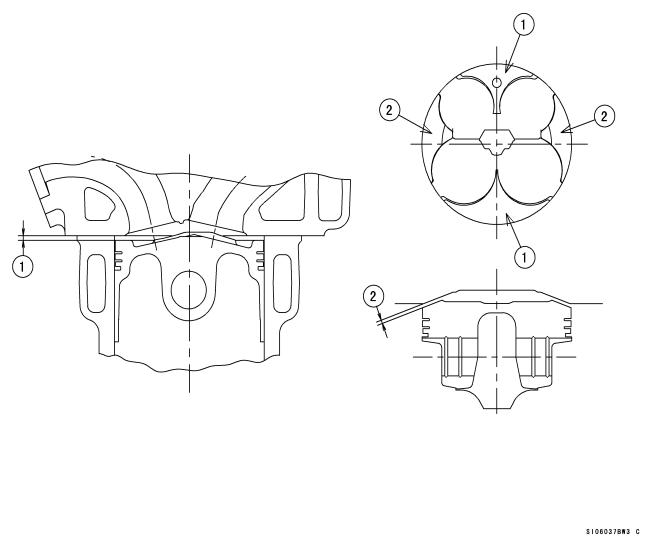
To adjust the cylinder compression, adjust the thickness of the cylinder head gasket and the cylinder base gasket or smooth the cylinder top surface to make the piston squish 0.65 ~ 0.8 mm. Keep the piston squish more than 0.65 mm.
Position the piston at Top Dead Center, and put a small piece of modeling clay on the shoulder of the piston. Install the cylinder head gasket and cylinder head, and tighten the head bolts to the specified torque.
Remove the cylinder head and measure the thickness of the clay. The thickness of the collapsed clay is the size of the squish.
Squish Measurement
[1] |
Front and Rear |
0.65 ~ 0.80 mm |
[2] |
Left and Right |
0.67 ~ 0.85 mm |
The most preferable squish measurement is [1] 0.65 mm/[2] 0.67 mm. Select proper cylinder head gasket and cylinder base gasket.
Note that by grinding the cylinder head surface only left and right squishes become narrower, while by grinding the cylinder top surface or decreasing the gasket-thickness all the squishes become narrower.
14
Cylinder Head Gasket
Part No. |
Thickness |
Note |
|
11004-0071 |
0.45 mm |
KIT |
|
11004-0070 |
0.50 mm |
KIT |
|
11004-0069 |
0.55 mm |
KIT |
|
11004-0068 |
0.60 mm |
KIT |
|
11004-0057 |
0.65 mm |
Original |
|
11004-0067 |
0.70 mm |
KIT |
|
|
|
|
|
|
|
|
|
1.Squish, Front/Rear
2.Squish, Left/Right
15
Crankshaft Main Journal and Connecting Rod Big End Bushings
To adjust clearance of crankshaft main journal you can select proper bush in accordance with the marks.
The kit bushings are improved in anti-seizuring characteristics as well as in wear-resistance as compared with the standard bushings.
1) Crankshaft Main Journal
Crankshaft Main Journal Diameter
1. Crankshaft Main Journal Diameter Marks
|
|
SIZE |
“1” mark |
: over 30.992 mm |
within 31.000 mm |
None |
: over 30.984 mm |
within 30.992 mm |
Crankcase Main Journal inside Diameter
1. Main Journal Diameter Marks
|
SIZE |
|
“{” mark |
: over 34.000 mm |
within 34.008 mm |
None |
: 34.008 mm and over |
within 34.016 mm |
16

Main Journal Bush
A. Size Color
|
Size Color |
|
Thickness mm |
Journal Number |
|
Part Number |
|
Part Number |
|
|||||||
|
|
|
(STD) |
|
|
|
(KIT) |
|
||||||||
|
|
|
|
|
|
|
|
|
|
|
|
|
|
|||
|
blue |
|
1.499-1.503 |
|
1-4 |
|
92139-0189 |
|
92139-0200 |
|
||||||
|
|
|
5 |
|
|
92139-0171 |
|
92139-0197 |
|
|||||||
|
|
|
|
|
|
|
|
|
|
|||||||
|
black |
|
1.495-1.499 |
|
1-4 |
|
92139-0190 |
|
92139-0201 |
|
||||||
|
|
|
5 |
|
|
92139-0172 |
|
92139-0198 |
|
|||||||
|
|
|
|
|
|
|
|
|
|
|||||||
|
brown |
|
1.491-1.495 |
|
1-4 |
|
92139-0191 |
|
92139-0202 |
|
||||||
|
|
|
5 |
|
|
92139-0173 |
|
92139-0199 |
|
|||||||
|
|
|
|
|
|
|
|
|
|
|||||||
|
Selection Table |
|
|
|
|
|
|
|
|
|
|
|
|
|
|
|
|
|
|
|
|
|
|
|
Size |
|
Journal |
|
Part |
|
Part |
|
|
|
Crankcase inner Diameter |
Crankshaft Diameter |
|
|
|
|
Number |
|
Number |
|
||||||
|
|
|
Color |
|
Number |
|
|
|
||||||||
|
|
|
|
|
|
|
|
|
|
(STD) |
|
(KIT) |
|
|||
|
|
|
|
|
|
|
|
|
|
|
|
|
|
|||
|
○ |
|
1 |
|
|
|
brown |
|
1-4 |
92139-0191 |
|
92139-0202 |
|
|||
|
(34.000 mm ~ 34.008 mm) |
(30.992 mm ~ 31.000 mm) |
|
|
5 |
92139-0173 |
|
92139-0199 |
|
|||||||
|
|
|
|
|
|
|||||||||||
|
○ |
|
NONE |
|
|
black |
|
1-4 |
92139-0190 |
|
92139-0201 |
|
||||
|
(34.000 mm ~ 34.008 mm) |
(30.984 mm ~ 30.992 mm) |
|
|
5 |
92139-0172 |
|
92139-0198 |
|
|||||||
|
|
|
|
|
|
|||||||||||
|
NONE |
|
1 |
|
|
|
black |
|
1-4 |
92139-0190 |
|
92139-0201 |
|
|||
|
(34.008 mm ~ 34.016 mm) |
(30.992 mm ~ 31.000 mm) |
|
|
5 |
92139-0172 |
|
92139-0198 |
|
|||||||
|
|
|
|
|
|
|||||||||||
|
NONE |
|
NONE |
|
|
blue |
|
1-4 |
92139-0189 |
|
92139-0200 |
|
||||
|
(34.008 mm ~ 34.016 mm) |
(30.984 mm ~ 30.992 mm) |
|
|
5 |
92139-0171 |
|
92139-0197 |
|
|||||||
|
|
|
|
|
|
|||||||||||
17
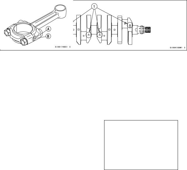
2) Crankpin
Crankpin Diameter
1. Crankpin Diameter Marks
“{” mark |
: |
over 29.992 mm |
within 30.000 mm |
None |
: |
29.984 mm and over |
within 29.992 mm |
Connecting Rod Big End Inside Diameter
Connecting Rod Big End Inside Diameter Marks
“{” mark |
: |
over 33.008 mm |
within 33.016 mm |
None |
: |
33.000 mm and over |
within 33.008 mm |
A.Inside Diameter Mark ({ or None)
B.Weight Mark, Alphabet (G.H etc)
Connecting Rod Big End Bushings
Size Color |
Thickness mm |
Part Number |
Part Number |
|
(STD) |
(KIT) |
|||
|
|
|||
blue |
1.485-1.490 |
92139-0165 |
92139-0194 |
|
|
|
|
|
|
black |
1.480-1.485 |
92139-0166 |
92139-0195 |
|
brown |
1.475-1.480 |
92139-0167 |
92139-0196 |
18
Selection Table
Connecting Rod Big End |
Crankpin Diameter Mark |
Size |
Part Number |
Part Number |
|
Inside Diameter |
Color |
(STD) |
(KIT) |
||
|
|||||
None |
○ |
brown |
92139-0167 |
92139-0196 |
|
(33.000 mm ~ 33.008 mm) |
(29.992 mm ~ 30.000 mm) |
||||
|
|
|
|||
None |
None |
black |
92139-0166 |
92139-0195 |
|
(33.000 mm ~ 33.008 mm) |
(29.984 mm ~ 29.992 mm) |
||||
|
|
|
|||
○ |
○ |
black |
92139-0166 |
92139-0195 |
|
(33.008 mm ~ 33.016 mm) |
(29.992 mm ~ 30.000 mm) |
||||
|
|
|
|||
○ |
None |
blue |
92139-0165 |
92139-0194 |
|
(33.008 mm ~ 33.016 mm) |
(29.984 mm ~ 29.992 mm) |
||||
|
|
|
Connecting Rod Bolts
Use the original connecting bolts and nuts.
The original connecting rod bolt has recesses at both ends to measure its length and determine the bolt stretch.
Install the original bolts into the connecting rod.
Before every tightening, use a point micrometer to measure the length of the bolts and record the values to find the bolt stretch.
Apply a small amount of molybdenum disulfide grease to the threads of bolts. Tighten the big end nuts at the torque of 11.8 ±2 N·m (1.2 ±0.2 kgf·m): reference Check the length of the bolts and find the bolt stretch.
Bolt Length after tightening – Bolt Length before tightening = Stretch
Bolt Stretch
Usable Range: 0.33 ~ 0.38 mm (0.013 ~ 0.015 in.)
Turn the big end nuts more until the bolt stretch reaches the usable range.
NOTE
Replace the original bolts with new ones if they have already been tightened up to usable range 2 times.
19
Loading...