


 Loading...
Ninja ZX-12R
Motorcycle
Service Manual

Quick Reference Guide
This quick reference guide will assist you in locating a desired topic or procedure.
•Bend the pages back to match the black tab of the desired chapter number with the black tab on the edge at each table of contents page.
•Refer to the sectional table of contents for the exact pages to locate the specific topic required.
General Information |
1 |
j |
Periodic Maintenance |
2 |
j |
Fuel System (DFI) |
3 |
j |
Cooling System |
4 |
j |
Engine Top End |
5 |
j |
Clutch |
6 |
j |
Engine Lubrication System |
7 |
j |
Engine Removal/Installation |
8 |
j |
Crankshaft/Transmission |
9 |
j |
Wheels/Tires |
10 |
j |
Final Drive |
11 |
j |
Brakes |
12 |
j |
Suspension |
13 |
j |
Steering |
14 |
j |
Frame |
15 |
j |
Electrical System |
16 |
j |
Troubleshooting |
17 |
j |

Ninja ZX-12R
Motorcycle
Service Manual
All rights reserved. No parts of this publication may be reproduced, stored in a retrieval system, or transmitted in any form or by any means, electronic mechanical photocopying, recording or otherwise, without the prior written permission of Quality Assurance Department/Consumer Products & Machinery Company/Kawasaki Heavy Industries, Ltd., Japan.
No liability can be accepted for any inaccuracies or omissions in this publication, although every possible care has been taken to make it as complete and accurate as possible.
The right is reserved to make changes at any time without prior notice and without incurring an obligation to make such changes to products manufactured previously. See your Motorcycle dealer for the latest information on product improvements incorporated after this publication.
All information contained in this publication is based on the latest product information available at the time of publication. Illustrations and photographs in this publication are intended for reference use only and may not depict actual model component parts.
© 2002 Kawasaki Heavy Industries, Ltd. |
Fourth Edition (1) : Mar. 5, 2004 (K) |
LIST OF ABBREVIATIONS
|
|
|
|
A |
ampere(s) |
lb |
pound(s) |
ABDC |
after bottom dead center |
m |
meter(s) |
AC |
alternating current |
min |
minute(s) |
ATDC |
after top dead center |
N |
newton(s) |
BBDC |
before bottom dead center |
Pa |
pascal(s) |
BDC |
bottom dead center |
PS |
horsepower |
BTDC |
before top dead center |
psi |
pound(s) per square inch |
°C |
degree(s) Celsius |
r |
revolution |
DC |
direct current |
rpm |
revolution(s) per minute |
F |
farad(s) |
TDC |
top dead center |
°F |
degree(s) Fahrenheit |
TIR |
total indicator reading |
ft |
foot, feet |
V |
volt(s) |
g |
gram(s) |
W |
watt(s) |
h |
hour(s) |
Ω |
ohm(s) |
L |
liter(s) |
|
|
Read OWNER’S MANUAL before operating.

EMISSION CONTROL INFORMATION
To protect the environment in which we all live, Kawasaki has incorporated crankcase emission (1) and exhaust emission (2) control systems in compliance with applicable regulations of the United States Environmental Protection Agency and California Air Resources Board. Additionally, Kawasaki has incorporated an evaporative emission control system (3) in compliance with applicable regulations of the California Air Resources Board on vehicles sold in California only.
1. Crankcase Emission Control System
This system eliminates the release of cranckcase vapors into the atmosphere. Instead, the vapors are routed through an oil separator to the inlet side of the engine. While the engine is operating, the vapors are drawn into combustion chamber, where they are burned along with the fuel and air supplied by the fuel injection system.
2. Exhaust Emission Control System
This system reduces the amount of pollutants discharged into the atmosphere by the exhaust of this motorcycle. The fuel, ignition, and exhaust systems of this motorcycle have been carefully designed and constructed to ensure an efficient engine with low exhaust pollutant levels.
The exhaust system of this model motorcycle manufactured primarily for sale in California includes a catalytic converter system.
3. Evaporative Emission Control System
Vapors caused by fuel evaporation in the fuel system are not vented into the atmosphere. Instead, fuel vapors are routed into the running engine to be burned, or stored in a canister when the engine is stopped. Liquid fuel is caught by a vapor separator and returned to the fuel tank.
The Clean Air Act, which is the Federal law covering motor vehicle pollution, contains what is commonly referred to as the Act’s "tampering provisions."
"Sec. 203(a) The following acts and the causing thereof are prohibited...
(3)(A) for any person to remove or render inoperative any device or element of design installed on or in a motor vehicle or motor vehicle engine in compliance with regulations under this title prior to its sale and delivery to the ultimate purchaser, or for any manufacturer or dealer knowingly to remove or render inoperative any such device or element of design after such sale and delivery to the ultimate purchaser.
(3)(B) for any person engaged in the business of repairing, servicing, selling, leasing, or trading motor vehicles or motor vehicle engines, or who operates a fleet of motor vehicles knowingly to remove or render inoperative any device or element of design installed on or in a motor vehicle or motor vehicle engine in compliance with regulations under this title following its sale and delivery to the ultimate purchaser..."
NOTE
○The phrase "remove or render inoperative any device or element of design" has been generally interpreted as follows:
1. Tampering does not include the temporary removal or rendering inoperative of devices or elements of design in order to perform maintenance.
2. Tampering could include:
a.Maladjustment of vehicle components such that the emission standards are exceeded.
b.Use of replacement parts or accessories which adversely affect the performance or durability of the motorcycle.
c.Addition of components or accessories that result in the vehicle exceeding the standards.
d.Permanently removing, disconnecting, or rendering inoperative any component or element of design of the emission control systems.

WE RECOMMEND THAT ALL DEALERS OBSERVE THESE PROVISIONS OF FEDERAL LAW, THE VIOLATION OF WHICH IS PUNISHABLE BY CIVIL PENALTIES NOT EXCEEDING $10,000 PER VIOLATION.
TAMPERING WITH NOISE CONTROL SYSTEM PROHIBITED
Federal law prohibits the following acts or the causing thereof: (1) The removal or rendering inoperative by any person other than for purposes of maintenance, repair, or replacement, of any device or element of design incorporated into any new vehicle for the purpose of noise control prior to its sale or delivery to the ultimate purchaser or while it is in use, or (2) the use of the vehicle after such device or element of design has been removed or rendered inoperative by any person.
•Among those acts presumed to constitute tampering are the acts listed below:
Replacement of the original exhaust system or muffler with a component not in compliance
•with Federal regulations.
•Removal of the muffler(s) or any internal portion of the muffler(s).
•Removal of the air box or air box cover.
Modifications to the muffler(s) or air inlet system by cutting, drilling, or other means if such modifications result in increased noise levels.

Foreword
This manual is designed primarily for use by trained mechanics in a properly equipped shop. However, it contains enough detail and basic information to make it useful to the owner who desires to perform his own basic maintenance and repair work. A basic knowledge of mechanics, the proper use of tools, and workshop procedures must be understood in order to carry out maintenance and repair satisfactorily. Whenever the owner has insufficient experience or doubts his ability to do the work, all adjustments, maintenance, and repair should be carried out only by qualified mechanics.
In order to perform the work efficiently and to avoid costly mistakes, read the text, thoroughly familiarize yourself with the procedures before starting work, and then do the work carefully in a clean area. Whenever special tools or equipment are specified, do not use makeshift tools or equipment. Precision measurements can only be made if the proper instruments are used, and the use of substitute tools may adversely affect safe operation.
For the duration of the warranty period, we recommend that all repairs and scheduled maintenance be performed in accordance with this service manual. Any owner maintenance or repair procedure not performed in accordance with this manual may void the warranty.
•To get the longest life out of your vehicle: Follow the Periodic Maintenance Chart in the
•Service Manual.
Be alert for problems and non-scheduled
•maintenance.
Use proper tools and genuine Kawasaki Motorcycle parts. Special tools, gauges, and testers that are necessary when servicing Kawasaki motorcycles are introduced by the Special Tool Catalog or Manual. Genuine parts provided as spare parts are listed in the
•Parts Catalog.
Follow the procedures in this manual care-
•fully. Don’t take shortcuts.
Remember to keep complete records of maintenance and repair with dates and any new parts installed.
How to Use This Manual
In this manual, the product is divited into its major systems and these systems make up the manual’s chapters. The Quick Reference
Guide shows you all of the product’s system and assists in locating their chapters. Each chapter in turn has its own comprehensive Table of Contents.
For example, if you want ignition coil information, use the Quick Reference Guide to locate the Electrical System chapter. Then, use the Table of Contents on the first page of the chapter to find the Ignition Coil section.
Whenever you see these WARNING and CAUTION symbols, heed their instructions! Always follow safe operating and maintenance practices.
 WARNING
This warning symbol identifies special instructions or procedures which, if not correctly followed, could result in personal injury, or loss of life.
CAUTION
This caution symbol identifies special instructions or procedures which, if not strictly observed, could result in damage to or destruction of equipment.
This manual contains four more symbols (in addition to WARNING and CAUTION) which will help you distinguish different types of information.
NOTE
○This note symbol indicates points of particular interest for more efficient and convenient operation.
•Indicatesdone. a procedural step or work to be ○Indicates a procedural sub-step or how to do the work of the procedural step it follows. It
also precedes the text of a NOTE.
Indicates a conditional step or what action to take based on the results of the test or inspection in the procedural step or sub-step it follows.
In most chapters an exploded view illustration of the system components follows the Table of Contents. In these illustrations you will find the instructions indicating which parts require specified tightening torque, oil, grease or a locking agent during assembly.
GENERAL INFORMATION 1-1
General Information |
|
|
|
|
1 |
|
|
Table of Contents |
|
|
|
Before Servicing ..................................................................................................................... |
1-2 |
|
|
Model Identification................................................................................................................. |
1-5 |
|
|
General Specifications............................................................................................................ |
1-6 |
|
|
Technical Information – KAWASAKI LOW EXHAUST EMISSION SYSTEM ......................... |
1-9 |
|
|
Technical Information – Monocoque Frame ........................................................................... |
1-12 |
|
|
Technical Information – Spark Plug ........................................................................................ |
1-13 |
|
|
Technical Information – Immobilizer System (ZX1200-B3)..................................................... |
1-14 |
|
|
Torque and Locking Agent...................................................................................................... |
1-17 |
|
|
Special Tools and Sealant ...................................................................................................... |
1-22 |
|
|
Cable, Wire, and Hose Routing (ZX1200-B1/B2)................................................................... |
1-29 |
|
|
Cable, Wire, and Hose Routing (ZX1200-B3) ........................................................................ |
1-46 |
|
|
Unit Conversion Table ............................................................................................................ |
1-60 |
|
|

1-2 GENERAL INFORMATION
Before Servicing
Before starting to service a motorcycle, careful reading of the applicable section is recommended to eliminate unnecessary work. Photographs, diagrams, notes, cautions, warnings, and detailed descriptions have been included wherever necessary. Nevertheless, even a detailed account has limitations, a certain amount of basic knowledge is also required for successful work.
Especially note the following:
(1) Dirt
Before removal and disassembly, clean the motorcycle. Any dirt entering the engine or other parts will work as an abrasive and shorten the life of the motorcycle. For the same reason, before installing a new part, clean off any dust or metal filings.
(2) Battery Cables
Disconnect the ground (–) cable from the battery before performing any disassembly operations on the motorcycle. This prevents the engine from accidentally turning over while work is being carried out, sparks from being generated while disconnecting the leads from electrical parts, as well as damage to the electrical parts themselves. For reinstallation, first connect the positive cable to the positive (+) terminal of the battery.
(3) Installation, Assembly
Generally, installation or assembly is the reverse of removal or disassembly. But if this Service Manual has installation or assembly procedures, follow them. Note parts locations and cable, lead, and hose routing during removal or disassembly so they can be installed or assembled in the same way. It is preferable to mark and record the locations and routing as much as possible.
(4) Tightening Sequence
Generally, when installing a part with several bolts, nuts, or screws, start them all in their holes and tighten them to a snug fit. Then tighten them evenly in a cross pattern. This is to avoid distortion of the part and/or causing gas or oil leakage. Conversely when loosening the bolts, nuts, or screws, first loosen all of them by about a quarter turn and then remove them. Where there is a tightening sequence indication in this Service Manual, the bolts, nuts, or screws must be tightened in the order and method indicated.
(5) Torque
When torque values are given in this Service Manual, use them. Either too little or too much torque may lead to serious damage. Use a good quality, reliable torque wrench.
(6) Force
Common sense should dictate how much force is necessary in assembly and disassembly. If a part seems especially difficult to remove or install, stop and examine what may be causing the problem. Whenever tapping is necessary, tap lightly using a wooden or plastic-faced mallet. Use an impact driver for screws (particularly for the removal of screws held by a locking agent) in order to avoid damaging the screw heads.
(7) Edges
Watch for sharp edges, especially during major engine disassembly and assembly. Protect your hands with gloves or a piece of thick cloth when lifting the engine or turning it over.
(8) High-Flash Point Solvent
A high-flash point solvent is recommended to reduce fire danger. A commercial solvent commonly available in North America is Stoddard solvent (generic name). Always follow manufacturer and container directions regarding the use of any solvent.
(9) Gasket, O-ring
Do not reuse a gasket or O-ring once it has been in service. The mating surfaces around the gasket should be free of foreign matter and perfectly smooth to avoid oil or compression leakage.
(10)Liquid Gasket, Non-Permanent Locking Agent
Follow manufacturer’s directions for cleaning and preparing surfaces where these compounds will be used. Apply sparingly. Excessive amounts may block engine oil passages and cause serious damage. An example of non-permanent locking agent commonly available in North America is Loctite Lock’n Seal (Blue).
(11)Press
A part installed using a press or driver, such as a wheel bearing, should first be coated with oil on its outer or inner circumference so that it will go into place smoothly.
GENERAL INFORMATION 1-3
Before Servicing
(12)Ball Bearing and Needle Bearing
Do not remove a ball bearing or a needle bearing unless it is absolutely necessary. Replace any ball or needle bearings that were removed with new ones, as removal generally damages bearings. Install bearings with the marked side facing out applying pressure evenly with a suitable driver. Only press on the race that forms the press fit with the base component to avoid damaging the bearings. This prevents severe stress on the balls or needles and races, and prevent races and balls or needles from being dented. Press a ball bearing until it stops at the stopper in the hole or on the shaft.
(13)Oil Seal and Grease Seal
Replace any oil or grease seals that were removed with new ones, as removal generally damages seals. When pressing in a seal which has manufacturer’s marks, press it in with the marks facing out. Seals should be pressed into place using a suitable driver, which contacts evenly with the side of seal, until the face of the seal is even with the end of the hole. Before a shaft passes through a seal, apply little high temperature grease on the lips to reduce rubber to metal friction.
(14)Circlip, Retaining Ring, and Cotter Pin
Replace any circlips and retaining rings, and cotter pins that were removed with new ones, as removal weakens and deforms them. When installing circlips and retaining rings, take care to compress or expand them only enough to install them and no more.
(15)Lubrication
Engine wear is generally at its maximum while the engine is warming up and before all the rubbing surfaces have an adequate lubricative film. During assembly, oil or grease (whichever is more suitable) should be applied to any rubbing surface which has lost its lubricative film. Old grease and dirty oil should be cleaned off. Deteriorated grease has lost its lubricative quality and may contain abrasive foreign particles.
Don’t use just any oil or grease. Some oils and greases in particular should be used only in certain applications and may be harmful if used in an application for which they are not intended. This manual makes reference to molybdenum disulfide grease (MoS2) and molybdenum disulfide oil in the assembly of certain engine and chassis parts. The molybdenum disulfide oil is a mixture of engine oil and molybdenum disulfide grease with a weight ratio (10 : 1), which can be made in your work shop. Always check manufacturer recommendations before using such special lubricants.
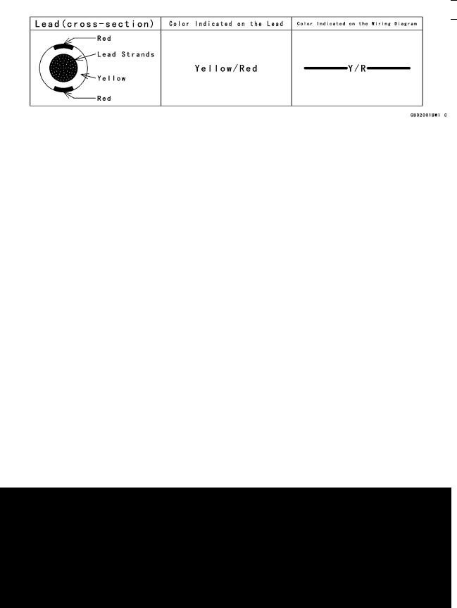
(16)Electrical Leads
All the electrical leads are either single-color or two-color and, with only a few exceptions, must be connected to leads of the same color. On any of the two-color leads there is a greater amount of one color and a lesser amount of a second color, so a two-color lead is identified by first the primary color and then the secondary color. For example, a yellow lead with thin red stripes is referred to as a "yellow/red" lead; it would be a "red/yellow" lead if the colors were reversed to make red the main color.
(17)Replacement Parts
When there is a replacement instruction, replace these parts with new ones every time they are removed. These replacement parts will be damaged or lose their original function once removed.

1-4 GENERAL INFORMATION
Before Servicing
(18)Inspection
When parts have been disassembled, visually inspect these parts for the following conditions or other damage. If there is any doubt as to the condition of them, replace them with new ones.
Abrasion |
Crack |
Hardening |
Warp |
Bent |
Dent |
Scratch |
Wear |
Color change |
Deterioration |
Seizure |
|
(19)Specifications
Specification terms are defined as follows:
"Standards" show dimensions or performances which brand-new parts or systems have. "Service Limits" indicate the usable limits. If the measurement shows excessive wear or dete-
riorated performance, replace the damaged parts. (20)Instrument
Use a meter that has enough accuracy for an accurate measurement.
Read the manufacturer’s instructions thoroughly before using the meter.
Incorrect values may lead to improper adjustments.
 User Manual")
GENERAL INFORMATION 1-5
Model Identification
ZX1200-B1 Left Side View
ZX1200-B1 Right Side View

1-6 GENERAL INFORMATION
General Specifications
|
|
|
|
Items |
|
ZX1200-B1 B3 |
|
Dimensions |
|
|
|
Overall Length |
2 085 mm (82.09 in.) |
||
Overall Width |
740 mm (29.13 in.) |
||
Overall Height |
1 200 mm (47.24 in.) |
||
Wheelbase |
1 450 mm (57.09 in.) |
||
Road Clearance |
120 mm (4.72 in.) |
||
Seat Height |
820 mm (32.28 in.) |
||
Dry Mass |
210 kg (463 lb) |
||
Curb Mass: |
|
|
|
Front |
125 kg (276 lb) |
||
Rear |
121 kg (267 lb) |
||
Fuel Tank Capacity |
19.0 L (5.0 US gal) |
||
Performance |
|
|
|
Minimum Turning Radius |
3.0 m (9.8 ft) |
||
Engine |
|
|
|
Type |
4-stroke, DOHC, 4-cylinder |
||
Cooling System |
Liquid-cooled |
||
Bore and Stroke |
83.0 × 55.4 mm (3.27 × 2.18 in.) |
||
Displacement |
1 199 mL (73.16 cu in.) |
||
Compression Ratio |
12.2 |
|
|
Maximum Horsepower |
(H) 131 kW (178 PS) @9 500 r/min (rpm), |
||
|
(AU) ZX1200-B1/B2: 130 kW (177 PS) @10 500 r/min (rpm), |
||
|
(AU) ZX1200-B3: 131 kW (178 PS) @10 500 r/min (rpm), |
||
|
(HR) 78.2 kW (106.4 PS) @8 500 r/min (rpm), |
||
|
(MY) ZX1200-B1/B2: 131 kW (178 PS) @ 9 500 r/min (rpm), |
||
|
(MY) ZX1200-B3: 128 kW (174 PS) @9 500 r/min (rpm) |
||
|
(US), (CA) – – – |
||
Maximum Torque |
(H, AU) 134 N·m (13.7 kgf·m, 99 ft·lb) @7 500 r/min (rpm), |
||
|
(MY) ZX1200-B1/B2: 134 N·m (13.7 kgf·m, 99 ft·lb) @7 500 |
||
|
r/min (rpm), |
||
|
(MY) ZX1200-B3: 130 N·m (13.3 kgf·m, 96 ft·lb) @7 500 r/min |
||
|
(rpm), |
||
|
(HR) 111 N·m (11.3 kgf·m, 82 ft·lb) @5 000 r/min (rpm), |
||
|
(US), (CA) – – – |
||
Carburetion System |
FI (Fuel Injection), ZX1200-B1/B2: MIKUNI 46 EIS × 4 |
||
|
ZX1200-B3: KEIHIN ( |
|
46 × 4) |
|
|
||
Starting System |
Electric starter |
||
Ignition System |
Battery and coil (transistorized) |
||
Timing Advance |
Electronically advanced (digital igniter in ECU) |
||
Ignition Timing |
10° BTDC @1 000 r/min (rpm) |
||
Spark Plugs |
NGK CR9EKPA |
||
Cylinder Numbering Method |
Left to right, 1-2-3-4 |
||
Firing Order |
1-2-4-3 |
|
|
|
|
|
|
|
|
GENERAL INFORMATION 1-7 |
|
|
|
|
General Specifications |
|
|
|
|
|
|
|
|
Items |
ZX1200-B1 B3 |
|
Valve Timing: |
|
|
Inlet: |
|
|
Open |
46° BTDC |
|
Close |
74° ABDC |
|
Duration |
300° |
|
Exhaust: |
|
|
Open |
69° BBDC |
|
Close |
45° ATDC |
|
Duration |
294° |
|
Lubrication System |
Forced lubrication (wet sump with cooler) |
|
Engine Oil: |
|
|
Grade |
API SE, SF or SG |
|
|
API SH or SJ with JASO MA |
|
Viscosity |
SAE 10W-40 |
|
Capacity |
3.6 L (3.8 US qt) |
|
Drive Train |
|
|
Primary Reduction System: |
|
|
Type |
Gear |
|
Reduction Ratio |
1.596 (83/52) |
|
Clutch Type |
Wet, multi disc |
|
Transmission: |
|
|
Type |
6-speed, constant mesh, return shift |
|
Gear Ratios: |
|
|
1st |
2.429 (34/14) |
|
2nd |
1.824 (31/17) |
|
3rd |
1.440 (36/25) |
|
4th |
1.250 (30/24) |
|
5th |
1.130 (26/23) |
|
6th |
1.033 (31/30) |
|
Final Drive System: |
|
|
Type |
Chain drive |
|
Reduction Ratio |
2.556 (46/18) |
|
Overall Drive Ratio |
4.215 @Top gear |
|
Frame |
|
|
Type |
Press backbone |
|
Caster (Rake Angle) |
23.5° |
|
Trail |
98 mm (3.86 in.) |
|
Front Tire: |
|
|
Type |
Tubeless |
|
Size |
120/70 ZR17 M/C (58W) |
|
Rear Tire: |
|
|
Type |
Tubeless |
|
Size |
200/50 ZR17 M/C (75W) |
|
|
|

1-8 GENERAL INFORMATION
General Specifications
|
|
|
Items |
|
ZX1200-B1 B3 |
Front Suspension: |
|
|
Type |
Telescopic fork (upside-down) |
|
Wheel Travel |
120 mm (4.72 in.) |
|
Rear Suspension: |
|
|
Type |
Swingarm (uni-trak) |
|
Wheel Travel |
140 mm (5.51 in.) |
|
Brake Type: |
|
|
Front |
Dual discs |
|
Rear |
Single disc |
|
Electrical Equipment |
|
|
Battery |
12 |
V 12 Ah |
Headlight: |
|
|
Type |
Semi-sealed beam |
|
Bulb |
12 |
V 60/55 W (quartz-halogen) × 2 |
Tail/Brake Light |
12 |
V 5/21 W × 2 |
Alternator: |
|
|
Type |
Three-phase AC |
|
Rated Output |
31 |
A/14 V @5 000 r/min (rpm) |
Specifications are subject to change without notice, and may not apply to every country. AU: Australian Model
US: U.S.A. Model
CA: Canadian Model
MY: Malaysian Model
HR: WVTA Approval Model, Honeycomb Catalytic Converter (Restricted Power) H: WVTA Approval Model, Honeycomb Catalytic Converter
GENERAL INFORMATION 1-9
Technical Information – KAWASAKI LOW EXHAUST EMISSION SYSTEM
Since the emission regulations become more severe, Kawasaki has adopted a type of simplified KAWASAKI LOW EXHAUST EMISSION SYSTEM (KLEEN), which have no catalyst protection system, according to each regulation of different countries.
The muffler with built-in catalyst has the same durability as the conventional muffler, however, do not use leaded gasoline and do not coast with the ignition system OFF. Running the engine without ignition damages catalyst.
Refer to the ZX900E Service Manual (Part No. 99924-1255) for more information about the KLEEN (theory, maintenance, and handling precautions), including the secondary air injection system.
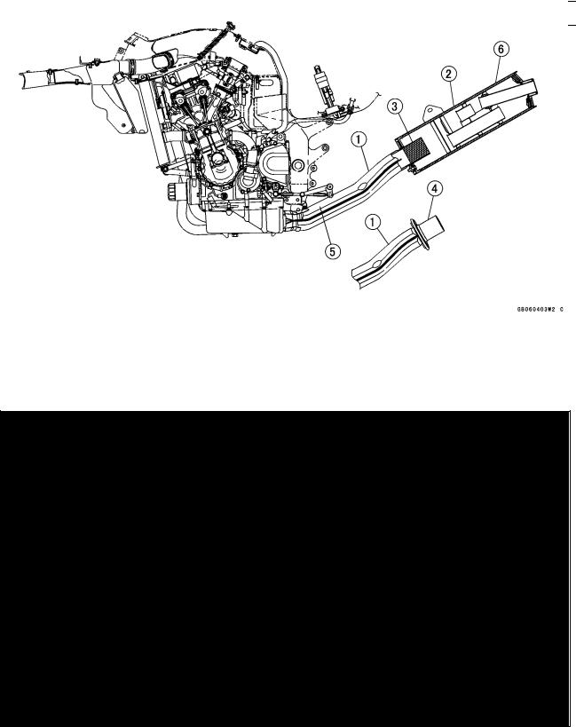
Honeycomb Type Catalytic Converter
○The converter is a three-way catalytic converter, and its surface is covered with alumina upon which platinum and rhodium are applied, and has a cylindrical metalic honeycomb structure made by bending a corrugated sheet and a flat sheet of stainless steel into a spiral of increasing diameter. The honeycomb structure is convenient for the catalytic converter because it has a large surface area but small size to react effectively and has low exhaust resistance. In addition, its inherent strength helps resist vibration, and has simple structure welded directly on the silencer.
○Generally, the temperature of the exhaust gas must be higher than activation temperature, so the converters are installed in the exhaust manifold rear end where the temperature of exhaust gas is still high. And, the converters will be activated even under low load conditions.
○After the exhaust gas is diluted with the secondary air injection, the catalytic converter works well because of rich oxygen to reduce CO, HC, and NOx. Accordingly, we can keep the exhaust gas emission within regulation.
○This type of converter works more efficiently as a three-way catalytic converter to reduce CO, HC, and NOx than the pipe type catalytic converter because of its more and denser catalysts.
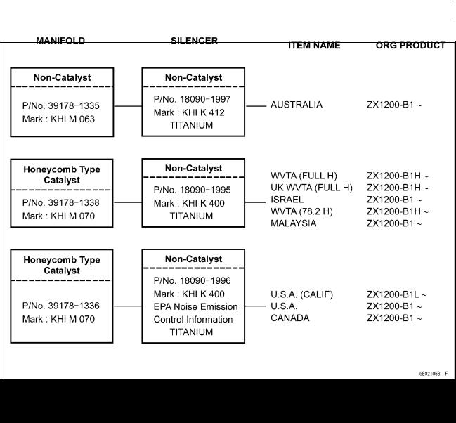
1.Manifold
2.Silencer
3.Honeycomb Type Catalyst
4.Non-Catalyst
5.Mark for Manifold
6.Mark for Silencer
1-10 GENERAL INFORMATION
Technical Information – KAWASAKI LOW EXHAUST EMISSION SYSTEM
Exhaust System (ZX1200-B1/B2)
78.2: Horsepower 78.2 kW (106.3 ps) Full: Full Power
H: Honeycomb Type Catalyst UK: United Kingdom Model
GENERAL INFORMATION 1-11
Technical Information – KAWASAKI LOW EXHAUST EMISSION SYSTEM
Exhaust System (ZX1200-B3)
78.2: Horsepower 78.2 kW (106.3 ps) Full: Full Power
H: Honeycomb Type Catalyst UK: United Kingdom Model
1-12 GENERAL INFORMATION
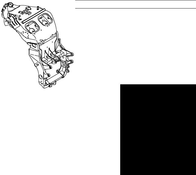
Technical Information – Monocoque Frame
Why a monocoque? Like all breakthrough innovations, the choice appears quite obvious after the |
||
fact. When large-section aluminium spars are wrapped around an already wide, large-displacement |
||
in-line Four engine, the resulting package must of necessity be wide. The ZX-12R’s all-aluminium box |
||
-section monocoque chassis eliminates these perimeter spars in favor of a large box section running |
||
over the top of the engine. |
|
|
This frame design surpasses the levels of chassis stiffness and strength associated with conven- |
||
tional aluminium twin-beam frames, but with considerably less breadth. Without the twin beams or |
||
other frame elements running around the side of the engine, the fairing can be much narrower, re- |
||
sulting in a much slimmer overall package and significantly better aerodynamics. Further, in a radical |
||
departure, the hollow structure also doubles as an airbox for the Ram Air system, eliminating the need |
||
for a space-consuming, conventional airbox. |
|
|
And ultimately, it is the synergy of combining a compact, massively powerful engine with this super |
||
stiff and slim chassis structure that explains much of the ZX-12R’s superlative high-speed perfor- |
||
mance. |
|
|
•All-new frame-integrated Ram Air system adds consider- |
||
able horsepower in the higher speed ranges. |
|
|
•Monocoque frame allows for the use of perfectly straight, |
||
highly efficient inlet ports. |
|
|
•Using the frame backbone as an airbox saves space and |
||
creates a very efficient airbox. |
|
|
•Battery mounts inside the frame and the battery cover is |
||
a structural element. |
|
|
•Revolutionary new all-aluminum monocoque frame for |
||
high rigidity and lightweight. |
|
|
•Huge box section and heat-freated |
cast |
steering |
head/swingarm pivot areas realize |
an |
extremely |
stiff structure and contribute to the ZX-12R’s superb |
||
high-speed stability and nimble, super sport handling |
||
performance. |
|
|
•By eliminating the dual large-section beams of conven- |
||
tional aluminum frames, this frame design makes possi- |
||
ble a much narrower and more compact overall package |
||
and greatly improves aerodynamics. |
|
|
GENERAL INFORMATION 1-13
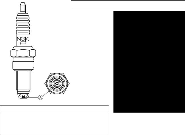
Technical Information – Spark Plug
ZX1200-B1 is equipped with the Kawasaki recommended spark plug (NGK CR9EKPA). By using the Kawasaki recommended spark plug, the idling stability, the fuel consumption improvement, and the maintenance free spark plug is planed.
This spark plug is calculated 3 or 4 times as durable as the usual one (NGK CR9EK).
Feature
1. This spark plug is more superior to the usual one with the ignition for the ignition point protruding.
2. Further, this spark plug is superior to the usual one with the endurance for the Pt alloy [A] covering around the center electrode and for the opposed area improvement of the side electrodes.
Specification
1. Standard Spark Plug CR9EKPA, two side electrodes,
M10 threads
2. Hotter Spark Plug CR8EKPA, two side electrodes, M10 threads
CAUTION
Use only the recommender spark plug. Do not use other spark plug, even though it may fit, because it could cause the engine failure of the idling stability, etc.
1-14 GENERAL INFORMATION
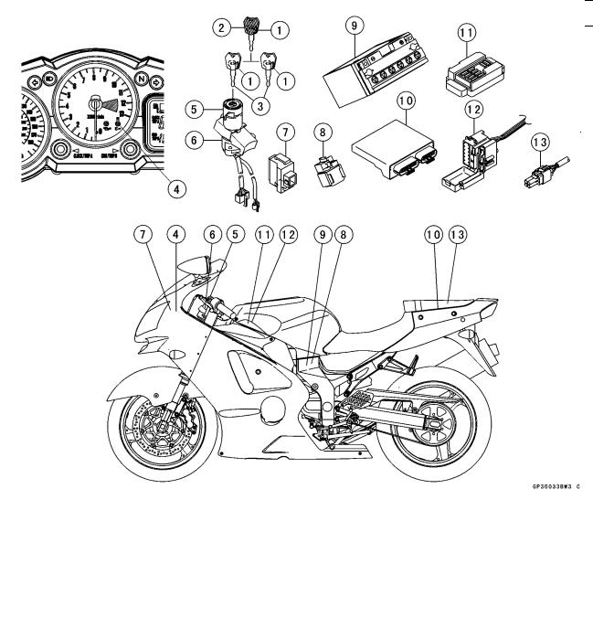
Technical Information – Immobilizer System (ZX1200-B3)
Overview
This system provides a theft proof device by means of matching a code between the inbuilt key transponder and the ECU (Electronic Control Unit). If this code does not match, the fuel pump, injectors, ignition system and sub-throttle valve actuator will not operate and the engine will not start.
Related Parts and Function
|
|
|
|
|
|
|
|
|
|
|
|
1. |
Transponder (Inside Keys) |
8. |
Starter Relay |
||
2. |
Master Key |
9. |
Battery |
||
3. |
User Keys |
10. |
Electronic Control Unit (ECU) |
||
4. |
FI Indicator Light |
11. |
Junction Box |
||
5. |
Immobilizer Antenna |
12. |
Fuse Box |
||
6. |
Ignition Switch |
13. |
Immobilizer/Kawasaki Diagnostic System |
||
7. |
Immobilizer Amplifier |
|
Connector |
||
Master Key (1 piece)
The master key (colored red) has an inbuilt transponder, containing a master key code. These codes are unique to each key. This code and an additional two user key codes must be registered in the ECU for the system to operate. The master key is necessary when registering user keys and should not be used as the main key to start the motorcycle except in emergencies (loss or damage of user keys). It should be kept in a safe place.
GENERAL INFORMATION 1-15
Technical Information – Immobilizer System (ZX1200-B3)
Transponder (in Keys)
The transponder (made by Texas Instruments, Inc.) has an integrated circuit with a unique code that also calculates data sent by the ECU. When the ignition switch is turned ON, the transponder is excited by the radio wave transmitted from the antenna and then transmits a unique code to the antenna.
User Key (2 pieces)
The user keys (colored black) should be used when riding the motorcycle. These keys have unique codes which differ from the master key. Up to a maximum of five user key codes can be stored by the ECU at any one time. These codes can not be registered to the ECU without firstly registering the master key code.
Antenna
The antenna transmits a radio wave to excite the transponder, receives the code from the transponder and then transmits the code to the ECU through the amplifier.
Ignition Switch
The ignition switch turns the main circuit ON and OFF.
Amplifier
The amplifier (which is approximately the same size as a match box), amplifies signals from the antenna and the ECU.
ECU
The ECU has the capacity to store a maximum of six key code memories (one master and five user keys). The owner can have a total of five user keys at any one time. The master key memory can not be rewritten after initial registration, whereas the user key memories can be rewritten as necessary. When the ECU communicates with the transponder, a cipher generator changes the code every time it is used to avoid cloning.
FI Indicator Light
The condition or the failure of the immobilizer system is indicated by various patterns of the FI indicator light blinking.
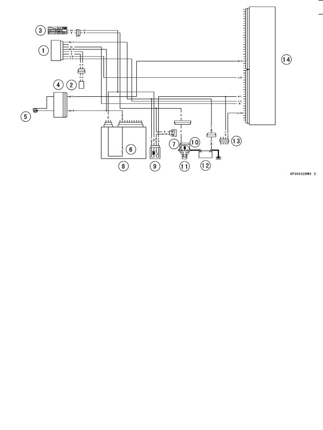
|
|
|
|
|
|
|
|
|
|
1. |
Immobilizer Amplifier |
9. |
ECU Main Relay |
|
2. |
Immobilizer Antenna |
10. |
Starter Relay |
|
3. |
Ignition Switch |
11. |
Main Fuse 30 A |
|
4. |
Meter Unit |
12. |
Battery 12 V 12 Ah |
|
5. |
FI Indicator Light |
13. |
Immobilizer/Kawasaki Diagnostic System |
|
6. |
Ignition Fuse 10 A |
|
Connector |
|
7. |
ECU Fuse 15 A |
14. |
Electronic Control Unit (ECU) |
|
8. |
Junction Box |
|
|
|

1-16 GENERAL INFORMATION
Technical Information – Immobilizer System (ZX1200-B3)
Sequence of Operation
1. Turn ON the ignition switch, the ECU, amplifier and antenna start working, and the meter assembly FI indicator lights up.
2. The transponder excited by radio waves transmitted from the antenna receives the ciphered code from the ECU.
3. The transponder transmits the calculated result from the key’s unique code to the ECU.
4. The ECU compares this with its memorized code, and if they match the engine can start. At this time, the FI indicator in the meter assembly is switched off.

GENERAL INFORMATION 1-17
Torque and Locking Agent
The following tables list the tightening torque for the major fasteners requiring use of a non-permanent locking agent or liquid gasket.
Letters used in the “Remarks” column mean:
L: Apply a non-permanent locking agent to the threads.
M: Apply molybdenum disulfide grease.
MO: Apply molybdenum disulfide oil solution.
O: Apply oil to the threads and seating surface.
S: Tighten the fasteners following the specified sequence.
SS: Apply silicone sealant.
St: Stake the fasteners to prevent loosening.
R: Replacement Parts
The table below, relating tightening torque to thread diameter, lists the basic torque for the bolts and nuts. Use this table for only the bolts and nuts which do not require a specific torque value. All of the values are for use with dry solvent-cleaned threads.
Basic Torque for General Fasteners
|
|
|
|
|
|
|
|
|
|
|
|
|
Threads |
|
|
|
|
|
Torque |
|
|
|
|
|
|
dia.(mm) |
|
N·m |
|
kgf·m |
|
ft·lb |
||||||
5 |
|
3.4 |
|
4.9 |
|
0.35 |
0.50 |
|
30 |
43 in·lb |
||
6 |
|
5.9 |
|
7.8 |
|
0.60 |
0.80 |
|
52 |
69 in·lb |
||
8 |
|
14 |
|
19 |
|
1.4 |
1.9 |
|
10.0 |
13.5 |
||
10 |
|
25 |
|
34 |
|
2.6 |
3.5 |
|
19.0 |
25 |
||
12 |
|
44 |
|
61 |
|
4.5 |
6.2 |
|
33 |
45 |
||
14 |
|
73 |
|
98 |
|
7.4 |
10.0 |
|
54 |
72 |
||
16 |
|
115 |
|
155 |
|
11.5 |
16.0 |
83 |
|
115 |
||
18 |
|
165 |
|
225 |
|
17.0 |
23.0 |
|
125 |
165 |
||
20 |
|
225 |
|
325 |
|
23 |
33 |
|
165 |
240 |
||
|
|
|
|
|
|
|
|
|
|
|
|
|
Fastener |
|
|
|
|
|
Torque |
|
|
|
|
Remarks |
|
|
|
|
|
N·m |
kgf·m |
|
ft·lb |
|
|
|||
|
|
|
|
|
|
|
|
|
|
|||
Fuel System (DFI) |
|
|
|
|
|
|
|
|
|
|
|
|
Fuel Level Sensor Bolts |
|
|
|
|
6.9 |
0.70 |
|
61 in·lb |
|
|
L |
|
Fuel Pump Bolts |
|
|
|
|
6.9 |
0.70 |
|
61 in·lb |
|
|
L, S |
|
Fuel Hose Clamp Bolts |
|
|
|
|
1.5 |
0.15 |
|
13 in·lb |
|
|
|
|
Inlet Air Pressure Sensor Bolt |
|
|
|
12 |
1.2 |
|
106 in·lb |
|
|
|
||
Inlet Air Pressure Sensor Bracket Nut |
|
12 |
1.2 |
|
106 in·lb |
|
|
|
||||
Inlet Air Temperature Sensor |
|
|
|
|
7.8 |
0.80 |
|
69 in·lb |
|
|
|
|
Atmospheric Pressure Sensor Bolts |
|
|
12 |
1.2 |
|
106 in·lb |
|
|
|
|||
Gear Position Switch Screws |
|
|
|
|
4.0 |
0.40 |
|
35 in·lb |
|
|
L |
|
Crankshaft Sensor Bolts |
|
|
|
|
6.0 |
0.60 |
|
53 in·lb |
|
|
|
|
Camshaft Position Sensor Bolt |
|
|
|
12 |
1.2 |
|
106 in·lb |
|
|
|
||
Crankshaft Position Sensor Rotor Bolt |
|
12 |
1.2 |
|
106 in·lb |
|
|
L |
||||
Delivery Pipe Screws (ZX1200-B1/B2) |
|
5.0 |
0.50 |
|
44 in·lb |
|
|
|
||||
Delivery Pipe Screws (ZX1200-B3) |
|
|
3.4 |
0.35 |
|
30 in·lb |
|
|
|
|||
Nipple Assy Screws |
|
|
|
|
3.5 |
0.35 |
|
31 in·lb |
|
|
|
|
Cooling System |
|
|
|
|
|
|
|
|
|
|
|
|
Coolant Hose Clamp Screws |
|
|
|
|
2.0 |
0.20 |
|
18 in·lb |
|
|
|
|

1-18 GENERAL INFORMATION
Torque and Locking Agent
|
|
|
|
|
|
Fastener |
|
Torque |
|
Remarks |
|
N·m |
kgf·m |
ft·lb |
|||
|
|
||||
Coolant Fitting Nozzle (ZX1200-B1/B2) |
12 |
1.2 |
106 in·lb |
L |
|
Coolant Drain Plug (Water Pump) |
12 |
1.2 |
106 in·lb |
|
|
Coolant Drain Plug (Cylinder) |
10 |
1.0 |
89 in·lb |
|
|
Radiator Fan Switch |
18 |
1.8 |
13 |
|
|
Water Temperature Sensor |
25 |
2.5 |
18 |
SS |
|
Water Pump Impeller Bolt |
10 |
1.0 |
89 in·lb |
|
|
Water Pump Cover Bolts |
12 |
1.2 |
106 in·lb |
|
|
Coolant Pipe Bolt |
12 |
1.2 |
106 in·lb |
|
|
Thermostat Housing Cover Bolts |
8.0 |
0.80 |
71 in·lb |
L |
|
Fitting Bolts |
12 |
1.2 |
106 in·lb |
|
|
Engine Top End |
|
|
|
|
|
Spark Plugs |
13 |
1.3 |
115 in·lb |
|
|
Air Suction Valve Cover Bolts |
12 |
1.2 |
106 in·lb |
|
|
Baffle Plate Bolts |
10 |
1.0 |
89 in·lb |
|
|
Cylinder Head Cover Bolts |
10 |
1.0 |
89 in·lb |
|
|
Crankshaft Sensor Cover Bolts |
15 |
1.5 |
11 |
L |
|
Camshaft Chain Tensioner Mounting Bolts |
10 |
1.0 |
89 in·lb |
L |
|
Camshaft Cap Bolts |
12 |
1.2 |
106 in·lb |
|
|
Upper Camshaft Chain Guide Bolts |
12 |
1.2 |
106 in·lb |
|
|
Front Camshaft Chain Guide Bolt (Upper) |
25 |
2.5 |
18 |
|
|
Front Camshaft Chain Guide Bolt (Lower) |
12 |
1.2 |
106 in·lb |
|
|
Rear Camshaft Chain Guide Bolt |
25 |
2.5 |
18 |
|
|
Camshaft Position Sensor Bolt |
12 |
1.2 |
106 in·lb |
|
|
Camshaft Position Sensor Rotor Bolt |
12 |
1.2 |
106 in·lb |
L |
|
Cylinder Head Bolts: M11 First Tighten |
23 |
2.3 |
17 |
MO, S |
|
|
|
|
|
(Washer) |
|
Cylinder Head Bolts: M11 Final Tighten |
59 |
6.0 |
44 |
MO, S |
|
|
|
|
|
(Washer) |
|
Cylinder Head Bolts: M7 |
20 |
2.0 |
15 |
S |
|
Cylinder Head Jacket Plugs |
22 |
2.2 |
16 |
L |
|
Throttle Body Holder Bolts |
12 |
1.2 |
106 in·lb |
|
|
Muffler Body Connection Nuts |
34 |
3.5 |
25 |
|
|
Guard Mounting Bolts |
12 |
1.2 |
106 in·lb |
|
|
Exhaust Pipe Holder Studs |
– |
– |
– |
(Stopped) |
|
Clutch |
|
|
|
|
|
Clutch Lever Clamp Bolts |
7.8 |
0.80 |
69 in·lb |
S |
|
Clutch Cover Bolts |
15 |
1.5 |
11 |
L (2) |
|
Clutch Cover Damper Plate Bolts |
7.0 |
0.70 |
62 in·lb |
L |
|
Clutch Spring Bolts |
8.8 |
0.90 |
78 in·lb |
|
|
Clutch Hub Nut |
135 |
14 |
100 |
R |
|
Engine Lubrication System |
|
|
|
|
|
Oil Level Gauge Bolts |
12 |
1.2 |
106 in·lb |
|

GENERAL INFORMATION 1-19
Torque and Locking Agent
|
|
|
|
|
|
Fastener |
|
Torque |
|
Remarks |
|
N·m |
kgf·m |
ft·lb |
|||
|
|
||||
Oil Filler Plug |
1.5 or |
0.15 or |
13 in·lb |
|
|
|
Hand |
Hand |
or Hand |
|
|
|
-Tight |
-Tight |
-Tight |
|
|
Engine Oil Drain Plug |
20 |
2.0 |
15 |
|
|
Oil Filter (Cartridge Type) |
31 |
3.2 |
23 |
EO, R |
|
Oil Cooler Passage Bolt |
78 |
7.8 |
58 |
EO |
|
Oil Cooler Mounting Bolts |
25 |
2.5 |
18 |
L |
|
Oil Pan Bolts |
15 |
1.5 |
11 |
L (1) |
|
Oil Pipe Holder Bolts |
12 |
1.2 |
106 in·lb |
L |
|
Oil Pressure Relief Valve |
15 |
1.5 |
11 |
L |
|
Oil Pressure Switch |
15 |
1.5 |
11 |
SS |
|
Oil Pressure Switch Terminal Screw |
1.5 |
0.15 |
13 in·lb |
|
|
Water Pump Impeller Bolt |
10 |
1.0 |
89 in·lb |
|
|
Engine Removal/Installation |
|
|
|
|
|
Engine Mounting Bolts and Nuts: M12 |
59 |
6.0 |
44 |
|
|
Engine Mounting Bolts and Nuts: M8 |
25 |
2.5 |
18 |
|
|
Upper Engine Mounting Bracket Bolt: M12 |
59 |
6.0 |
44 |
|
|
Lower Engine Mounting Bracket Bolt: M10 |
44 |
4.5 |
32 |
|
|
Adjusting Collars |
25 |
2.5 |
18 |
|
|
Crankshaft/Transmission |
|
|
|
|
|
Breather Plate Bolts |
10 |
1.0 |
89 in·lb |
L |
|
Breather Tube Bracket Bolts |
12 |
1.2 |
106 in·lb |
|
|
Crankcase Bolts: M10 |
50 |
5.0 |
37 |
MO, S |
|
Upper Crankcase Bolts: M8, L85 |
28 |
2.8 |
21 |
S |
|
Upper Crankcase Bolts: M7 |
25 |
2.5 |
18 |
S |
|
Lower Crankcase Bolts: M8, L99 |
23 |
2.3 |
17 |
S |
|
Lower Crankcase Bolts: M7 |
20 |
2.0 |
15 |
S |
|
Oil Passage Plugs (Each Side) |
20 |
2.0 |
15 |
L |
|
Connecting Rod Big End Nuts |
in the text |
← |
← |
← |
|
Timing Rotor Bolt |
39 |
4.0 |
29 |
|
|
Starter Torque Limiter Cover Bolts |
12 |
1.2 |
106 in·lb |
L |
|
Oil Pressure Switch |
15 |
1.5 |
11 |
SS |
|
Gear Positioning Lever Bolt |
10 |
1.0 |
89 in·lb |
L |
|
Shift Shaft Return Spring Pin (Bolt) |
30 |
3.0 |
22 |
L |
|
Speed Sensor Bolt |
12 |
1.2 |
106 in·lb |
L |
|
Shift Drum Bearing Holder Bolt |
12 |
1.2 |
106 in·lb |
L |
|
Shift Drum Bearing Holder Screw |
5.4 |
0.55 |
48 in·lb |
L |
|
Shift Drum Cam Bolt |
12 |
1.2 |
106 in·lb |
L |
|
Balancer Shaft Clamp Lever Bolt |
25 |
2.5 |
18 |
L |
|
Balancer Shaft Clamp Bolt |
12 |
1.2 |
106 in·lb |
|
|
Oil Pipe Holder Bolts (Crankshaft Pipe) |
12 |
1.2 |
106 in·lb |
L |
|
Oil Pipe Holder Bolt (Transmission Pipe) |
12 |
1.2 |
106 in·lb |
|
|
Oil Nozzle |
2.5 |
0.25 |
22 in·lb |
St |

1-20 GENERAL INFORMATION
Torque and Locking Agent
|
|
|
|
|
|
Fastener |
|
Torque |
|
Remarks |
|
N·m |
kgf·m |
ft·lb |
|||
|
|
||||
Starter Clutch Shaft Bolt |
25 |
2.5 |
18 |
L |
|
Starter Clutch Shaft Plate Bolt |
12 |
1.2 |
106 in·lb |
L |
|
Wheels/Tires |
|
|
|
|
|
Front Axle Clamp Bolts |
20 |
2.0 |
15 |
AL |
|
Front Axle Nut |
125 |
13 |
92 |
|
|
Rear Axle Nut |
125 |
13 |
92 |
|
|
Rear Sprocket Nuts |
59 |
6.0 |
44 |
|
|
Air Valve Cap |
0.15 |
0.015 |
1.3 in·lb |
|
|
Final Drive |
|
|
|
|
|
Engine Sprocket Nut |
127 |
13 |
94 |
MO |
|
Engine Sprocket Cover Bolts |
12 |
1.2 |
106 in·lb |
|
|
Chain Guide Bolt |
12 |
1.2 |
106 in·lb |
L |
|
Rear Sprocket Nuts |
59 |
6.0 |
44 |
|
|
Rear Axle Nut |
125 |
13 |
92 |
|
|
Brakes |
|
|
|
|
|
Bleed Valves |
7.8 |
0.80 |
69 in·lb |
|
|
Brake Hose Banjo Bolts |
25 |
2.5 |
18 |
|
|
Brake Lever Pivot Bolt |
1.2 |
0.12 |
11 in·lb |
Si |
|
Brake Lever Pivot Bolt Locknut |
6.0 |
0.60 |
52 in·lb |
|
|
Front Reservoir Cap Screws |
1.5 |
0.15 |
13 in·lb |
|
|
Front Brake Light Switch Screws |
1.2 |
0.12 |
11 in·lb |
|
|
Front Master Cylinder Clamp Bolts |
8.8 |
0.90 |
78 in·lb |
S |
|
Front Brake Pad Spring Bolts (ZX1200-B1/B2) |
3.0 |
0.30 |
27 in·lb |
|
|
Front Caliper Mounting Bolts |
34 |
3.5 |
25 |
|
|
Front Caliper Assembly Bolts |
21 |
2.1 |
15 |
|
|
Brake Disc Mounting Bolts |
27 |
2.8 |
20 |
L |
|
Front Brake Pad Pins (ZX1200-B3) |
15 |
1.5 |
11 |
|
|
Rear Caliper Mounting Bolts |
25 |
2.5 |
18 |
|
|
Rear Caliper Assembly Bolts |
30 |
3.0 |
22 |
|
|
Brake Pedal Mounting Bolt |
8.8 |
0.90 |
78 in·lb |
|
|
Rear Master Cylinder Mounting Bolts |
25 |
2.5 |
18 |
|
|
Rear Master Cylinder Push Rod Locknut |
18 |
1.8 |
13 |
|
|
Suspension |
|
|
|
|
|
Front Fork Clamp Bolts (Upper) |
20 |
2.0 |
15 |
|
|
Front Fork Clamp Bolts (Lower) |
20 |
2.0 |
15 |
AL |
|
Front Fork Top Plugs |
23 |
2.3 |
17 |
|
|
Piston Rod Nut |
28 |
2.8 |
21 |
|
|
Front Fork Bottom Allen Bolts |
40 |
4.0 |
30 |
L |
|
Front Axle Clamp Bolts |
20 |
2.0 |
15 |
AL |
|
Rear Shock Absorber Bracket Nut |
59 |
6.0 |
44 |
|
|
Rear Shock Absorber Nuts (Upper and Lower) |
34 |
3.5 |
25 |
|
|
Swingarm Pivot Shaft Nut |
125 |
13 |
92 |
|
|
Swingarm Pivot Shaft Lock Nut |
98 |
10 |
72 |
|
Loading...