


VULCAN 1600 CLASSIC
VN1600 CLASSIC
Motorcycle
Service Manual


Quick Reference Guide
|
|
|
|
|
|
|
|
|
General |
Information |
1 |
j |
|
|
|
|
|
|
|
|
|
|
Periodic |
Maintenance |
2 |
j |
|
|
|
|
|
|
|
|
|
|
Fuel |
System (DFI) |
3 |
j |
|
|
|
|
|
|
|
|
|
|
Cooling System |
4 |
j |
||
|
|
|
|
|
|
|
|
|
Engine |
Top End |
5 |
j |
|
|
|
|
|
|
|
|
|
|
Clutch |
|
6 |
j |
|
|
|
|
|
|
|
|
|
|
Engine |
Lubrication System |
7 |
j |
|
|
|
|
|
|
|
|
|
|
Engine |
Removal/Installation |
8 |
j |
|
|
|
|
|
|
|
|
|
|
Crankshaft/Transmission |
9 |
j |
||
|
|
|
|
|
|
|
|
|
Wheels/Tires |
10 |
j |
||
|
|
|
|
|
|
|
|
|
Final |
Drive |
11 |
j |
|
|
|
|
|
|
|
|
|
|
Brakes |
|
12 |
j |
|
|
|
|
|
|
|
|
|
|
Suspension |
13 |
j |
||
|
|
|
|
|
|
|
|
|
Steering |
|
14 |
j |
|
|
|
|
|
|
|
|
|
|
Frame |
|
15 |
j |
|
|
|
|
|
|
|
|
|
|
Electrical System |
16 |
j |
||
This |
quick |
reference guide will assistAppendix |
17 |
j |
|||||||||
you in locating |
a |
desired |
topic or |
pro |
|
|
|
|
|||||
cedure. |
|
|
|
|
|
|
|
|
|
|
|
|
|
•Bend the |
pages |
back |
to |
match |
the |
|
|
|
|
||||
black |
tab |
of |
the |
desired |
chapter |
num |
|
|
|
|
|||
ber |
with |
|
the |
black tab on the edge at |
|
|
|
|
|||||
each table of contents page. |
|
|
|
|
|
||||||||
•Refer to |
the sectional |
table |
of contents |
|
|
|
|
||||||
for the |
exact |
pages |
to locate the |
spe |
|
|
|
|
|||||
cific |
topic |
required. |
|
|
|
|
|
|
|
|
|||


VULCAN 1600 CLASSIC
VN1600 CLASSIC
Motorcycle
Service Manual
|
All |
rights |
reserved. |
No |
|
parts |
of |
this |
publication |
may |
be |
reproduced, |
stored |
in |
a |
retrieval |
syste |
||||||||||||
transmitted |
|
in |
any |
form |
|
|
or by any means, electronic mechanical photocopying, |
recording |
or |
otherwis |
|||||||||||||||||||
without the prior written permission of Quality Assurance Department/Consumer Products & Machinery |
|||||||||||||||||||||||||||||
Company/Kawasaki Heavy |
|
Industries, Ltd., |
Japan. |
|
|
|
|
|
|
|
|
|
|
|
|
||||||||||||||
|
No liability can |
be |
accepted |
for |
any |
inaccuracies isorsionsomin |
this |
publication, |
although |
every possible |
|
||||||||||||||||||
care has been taken to |
|
make it as |
complete and accurate as possible. |
|
|
|
|
|
|
|
|
||||||||||||||||||
|
The |
right |
is |
reserved |
|
to make |
changes |
at |
any time without |
prior |
notice |
and without incurring an ob |
|||||||||||||||||
to |
|
make |
|
such |
changes |
|
to |
products |
manufactured |
previously. |
See |
your |
Motorcycle |
dealer |
for |
the |
la |
||||||||||||
information |
|
on |
product improvements incorporated after |
this |
publication. |
|
|
|
|
|
|
|
|
|
|||||||||||||||
|
All information |
contained |
|
in |
this |
publication is |
basedthe lateston |
product information |
available |
at |
the |
time |
|
||||||||||||||||
of |
|
publication. |
Illustrations |
|
and photographs in |
this publication are intended |
for |
reference |
use |
only and |
m |
||||||||||||||||||
not |
depict |
|
actual |
model |
|
component |
parts. |
|
|
|
|
|
|
|
|
|
|
|
|
|
|||||||||
© |
|
2003 |
Kawasaki |
Heavy |
|
Industries, |
Ltd. |
|
|
|
Second Edition (1) |
: |
Aug. |
25, |
2003 (M) |
|
|
||||||||||||
|
|
|
|
LIST |
OF |
ABBREVIATIONS |
|
|
|
|
A |
ampere(s) |
|
|
|
lb |
pound(s) |
|
|
||
ABDC |
after |
bottom |
dead center |
m |
meter(s) |
|
|
|||
AC |
alternating |
current |
|
min |
minute(s) |
|
|
|||
ATDC |
after |
top |
dead center |
N |
newton(s) |
|
|
|||
BBDC |
before |
bottom |
dead |
center |
Pa |
pascal(s) |
|
|
||
BDC |
bottom dead |
center |
|
PS |
horsepower |
|
||||
BTDC |
before |
top |
dead center |
psi |
pound(s) |
per |
square inch |
|||
°C |
degree(s) |
Celsius |
|
r |
revolution |
|
|
|||
DC |
direct |
current |
|
|
r/min, rpm |
revolution(s) per minute |
||||
F |
farad(s) |
|
|
|
TDC |
top |
dead |
center |
||
°F |
degree(s) |
Fahrenheit |
|
TIR |
total |
indicator |
reading |
|||
ft |
foot, feet |
|
|
|
V |
volt(s) |
|
|
||
g |
gram(s) (mass) |
|
W |
watt(s) |
|
|
||||
h |
hour(s) |
|
|
|
Ω |
ohm(s) |
|
|
||
kg |
(mass) |
|
|
|
|
|
|
|
|
|
kgf |
(force) |
|
|
|
|
|
|
|
|
|
L |
liter(s) |
|
|
|
|
|
|
|
|
|
Read OWNER’S MANUAL before operating.

|
|
|
|
|
|
|
|
|
|
|
EMISSION |
CONTROL |
|
INFORMATION |
|
|
|
|
|
|
|
|
|
|
|
|
|
|
|
|
|||||||||||||||||||||||||
|
To protect the environment in |
which |
we |
|
all live, |
Kawasaki |
|
has incorporated |
crankcase |
emis |
|
||||||||||||||||||||||||||||||||||||||||||||
sion |
(1) |
and |
|
exhaust |
emission (2) |
|
control |
systems in |
compliance |
|
with |
|
applicable |
|
regulations |
of |
|
||||||||||||||||||||||||||||||||||||||
the United States Environmental Protection Agency and California Air |
Resources |
Board. |
Addi |
|
|||||||||||||||||||||||||||||||||||||||||||||||||||
tionally, |
|
Kawasaki |
has incorporated |
|
an |
|
evaporative |
emission |
control |
system |
(3) in |
compliance |
|
|
|||||||||||||||||||||||||||||||||||||||||
with applicable regulations of the |
|
California |
Air |
Resources |
|
Board on |
|
vehicles |
sold in |
California |
|
||||||||||||||||||||||||||||||||||||||||||||
only. |
|
|
|
|
|
|
|
|
|
|
|
|
|
|
|
|
|
|
|
|
|
|
|
|
|
|
|
|
|
|
|
|
|
|
|
|
|
|
|
|
|
|
|
|
|
|
|
|
|
|
|
|
|
|
|
1. |
Crankcase |
|
Emission |
Control System |
|
|
|
|
|
|
|
|
|
|
|
|
|
|
|
|
|
|
|
|
|
|
|
|
|
|
|
|
|
|
|
|
|
|
|
|
|||||||||||||||
This system eliminates the release |
|
of crankcase |
|
vapors into |
|
the atmosphere. Instead, the vapors |
|
||||||||||||||||||||||||||||||||||||||||||||||||
are |
routed |
through |
an |
oil separator |
|
to |
|
thedeinletof sithe |
engine. |
|
While the |
engine is |
|
operating, |
|
|
|
||||||||||||||||||||||||||||||||||||||
the vapors are drawn into combustion chamber, |
where |
|
they |
|
are |
burned |
along |
with the |
fuel |
and |
air |
||||||||||||||||||||||||||||||||||||||||||||
supplied |
by |
the |
|
fuel injection |
system. |
|
|
|
|
|
|
|
|
|
|
|
|
|
|
|
|
|
|
|
|
|
|
|
|
|
|
|
|
|
|
|
|
|
|
|
|
|
|
||||||||||||
2. Exhaust Emission Control System |
|
|
|
|
|
|
|
|
|
|
|
|
|
|
|
|
|
|
|
|
|
|
|
|
|
|
|
|
|
|
|
|
|
|
|
|
|
||||||||||||||||||
This |
system |
|
reduces |
the amount |
|
of |
|
pollutants |
|
discharged into |
|
the |
atmosphere |
by |
the |
exhaust |
|
||||||||||||||||||||||||||||||||||||||
of this |
motorcycle. |
|
The |
fuel, ignition, |
|
and |
|
exhaust |
|
systems of this motorcycle have been carefully |
|
||||||||||||||||||||||||||||||||||||||||||||
designed and constructed to ensure an |
|
efficient |
|
engine |
with low |
exhaust |
pollutant levels. |
|
|
|
|
||||||||||||||||||||||||||||||||||||||||||||
The exhaust system of this model motorcycle |
|
manufactured |
|
primarily |
|
for |
|
sale in |
California in |
|
|||||||||||||||||||||||||||||||||||||||||||||
cludes |
a |
|
catalytic |
converter |
system. |
|
|
|
|
|
|
|
|
|
|
|
|
|
|
|
|
|
|
|
|
|
|
|
|
|
|
|
|
|
|
|
|
|
|
|
|
|
|
|
|||||||||||
3. Evaporative Emission Control System |
|
|
|
|
|
|
|
|
|
|
|
|
|
|
|
|
|
|
|
|
|
|
|
|
|
|
|
|
|
|
|
|
|
||||||||||||||||||||||
Vapors |
caused |
|
by |
fuel |
evaporation in |
|
the |
|
fuel |
|
system |
are |
|
not |
|
vented into |
the |
atmosphere. |
In |
||||||||||||||||||||||||||||||||||||
stead, |
fuel |
vapors |
are |
routed |
into |
|
the |
|
|
running |
|
engine |
to |
|
be |
|
burned, |
|
or |
|
stored |
in |
a |
canister |
whe |
||||||||||||||||||||||||||||||
the |
engine is |
stopped. |
Liquid |
|
fuel |
is |
caught |
|
by |
|
a |
vapor separator and returned to the fuel tank. |
|||||||||||||||||||||||||||||||||||||||||||
|
The Clean Air Act, which is the Federal law |
|
covering motor |
vehicle |
|
pollution, |
contains |
what is |
|
||||||||||||||||||||||||||||||||||||||||||||||
commonly referred |
to |
as |
the |
Act’s |
|
"tampering |
provisions." |
|
|
|
|
|
|
|
|
|
|
|
|
|
|
|
|
|
|
|
|
|
|
|
|
||||||||||||||||||||||||
|
"Sec. 203(a) The following acts and the causing thereof |
|
are |
|
prohibited... |
|
|
|
|
|
|
|
|
|
|||||||||||||||||||||||||||||||||||||||||
(3)(A) for |
any |
|
person |
to |
remove |
or |
|
render inoperative |
any |
|
device |
|
or |
|
element |
of |
|
design installed |
|
||||||||||||||||||||||||||||||||||||
|
|
on or in |
|
a |
|
motor |
vehicle |
or |
motor |
vehicle |
|
engine in |
compliance |
|
with |
|
regulations |
under |
|
this |
|
||||||||||||||||||||||||||||||||||
|
|
title |
prior |
to its |
sale |
and |
delivery to |
the |
ultimate |
|
purchaser, |
or |
for |
any |
|
manufacturer |
or |
dealer |
|||||||||||||||||||||||||||||||||||||
|
|
knowingly to |
|
remove |
or |
render |
|
inoperative |
|
any such device or element of design |
after |
|
such |
||||||||||||||||||||||||||||||||||||||||||
|
|
sale and delivery to the ultimate purchaser. |
|
|
|
|
|
|
|
|
|
|
|
|
|
|
|
|
|
|
|
|
|
|
|
|
|
|
|
|
|||||||||||||||||||||||||
(3)(B) for |
any |
|
person |
engaged in the |
|
business |
|
of repairing, |
|
servicing, |
selling, leasing, |
or trading |
|
||||||||||||||||||||||||||||||||||||||||||
|
|
motor |
vehicles or motor vehicle engines, |
|
or |
who operates a fleet of motor vehicles know |
|||||||||||||||||||||||||||||||||||||||||||||||||
|
|
ingly |
to |
|
remove |
or |
render inoperative |
any |
|
device or element of design installed on or in a |
|||||||||||||||||||||||||||||||||||||||||||||
|
|
motor vehicle or motor vehicle |
|
engine |
|
in |
|
compliance |
|
with regulations |
under |
this |
title |
follow |
|
||||||||||||||||||||||||||||||||||||||||
|
|
ing its |
sale |
and |
delivery |
to |
the |
|
ultimate |
purchaser..." |
|
|
|
|
|
|
|
|
|
|
|
|
|
|
|
|
|
|
|
|
|
|
|
||||||||||||||||||||||
|
|
|
|
|
|
|
|
|
|
|
|
|
|
|
|
|
|
|
|
|
|
NOTE |
|
|
|
|
|
|
|
|
|
|
|
|
|
|
|
|
|
|
|
|
|
|
|
|
|
|
|
|
|
|
|
||
The |
phrase |
"remove |
or |
render inoperative |
any |
|
device |
or |
|
element |
|
of |
|
design" |
|
has |
been |
gener |
|||||||||||||||||||||||||||||||||||||
○interpreted as |
follows: |
|
|
|
|
|
|
|
|
|
|
|
|
|
|
|
|
|
|
|
|
|
|
|
|
|
|
|
|
|
|
|
|
|
|
|
|
|
|
|
|
|
|
|
|
|
|||||||||
|
1. Tampering |
does |
not include |
|
the |
|
temporary removal |
|
or |
rendering inoperative |
of |
de |
|
|
|||||||||||||||||||||||||||||||||||||||||
|
|
vices |
or |
elements |
of |
|
design in |
|
|
order |
to |
perform |
|
maintenance. |
|
|
|
|
|
|
|
|
|
|
|
|
|||||||||||||||||||||||||||||
|
2. Tampering could include: |
|
|
|
|
|
|
|
|
|
|
|
|
|
|
|
|
|
|
|
|
|
|
|
|
|
|
|
|
|
|
|
|
|
|
|
|
|
|
|
|
|
|||||||||||||
|
a.Maladjustment |
of |
vehicle |
components |
|
such |
|
that |
|
|
the |
|
emission |
|
standards |
are |
ex |
|
|||||||||||||||||||||||||||||||||||||
|
|
ceeded. |
|
|
|
|
|
|
|
|
|
|
|
|
|
|
|
|
|
|
|
|
|
|
|
|
|
|
|
|
|
|
|
|
|
|
|
|
|
|
|
|
|
|
|
|
|
|
|
|
|
||||
|
b.Use |
of |
|
replacement |
parts |
|
or |
|
|
accessories |
which |
|
adversely |
|
affect |
the |
|
performance |
|
||||||||||||||||||||||||||||||||||||
|
|
or durability of the motorcycle. |
|
|
|
|
|
|
|
|
|
|
|
|
|
|
|
|
|
|
|
|
|
|
|
|
|
|
|
|
|
|
|
|
|
|
|||||||||||||||||||
|
c.Addition |
of components |
or |
accessoriesat thresult in |
the |
vehicle |
exceeding the |
stan |
|
|
|
||||||||||||||||||||||||||||||||||||||||||||
|
|
dards. |
|
|
|
|
|
|
|
|
|
|
|
|
|
|
|
|
|
|
|
|
|
|
|
|
|
|
|
|
|
|
|
|
|
|
|
|
|
|
|
|
|
|
|
|
|
|
|
|
|
|
|||
|
d.Permanently removing, |
|
disconnecting, |
|
or |
|
rendering inoperative |
|
any |
|
component or |
|
|
|
|
||||||||||||||||||||||||||||||||||||||||
|
|
element of |
|
design |
of |
|
the |
emission |
|
control |
|
systems. |
|
|
|
|
|
|
|
|
|
|
|
|
|
|
|
|
|
|
|
|
|
||||||||||||||||||||||
WE RECOMMEND THAT ALL DEALERS OBSERVE THESE |
|
PROVISIONS |
|
OF |
FEDERAL |
LAW, |
|
||||||||||||||||||||||||||||||||||||||||||||||||
THE VIOLATION |
|
OF |
WHICH IS PUNISHABLE BY CIVIL |
PENALTIES |
|
NOT EXCEEDING |
|
|
|
|
|||||||||||||||||||||||||||||||||||||||||||||
$10,000 |
|
PER |
VIOLATION. |
|
|
|
|
|
|
|
|
|
|
|
|
|
|
|
|
|
|
|
|
|
|
|
|
|
|
|
|
|
|
|
|
|
|
|
|
|
|
|
|
|
|
||||||||||

TAMPERING WITH NOISE CONTROL SYSTEM PROHIBITED
Federal law |
prohibits the following acts or the causing thereof: (1) The removal or rendering |
|
||||||||||||||||||||||||||
inoperative |
by any |
|
person other |
than |
for purposes |
of maintenance, repair, or replacement, |
of any |
|
||||||||||||||||||||
device |
or |
element |
of |
design incorporated |
into |
any |
new vehicle for the purpose of |
noise |
control |
|||||||||||||||||||
prior |
to its |
sale |
or delivery |
to |
the |
ultimate |
purchaser |
or |
while it is in |
use, |
or (2) |
the use of |
the |
|||||||||||||||
vehicle |
after |
such |
device |
or |
|
element |
of |
design |
has |
been |
removed |
or |
rendered |
inoperative |
by |
|||||||||||||
any |
person. |
|
|
|
|
|
|
|
|
|
|
|
|
|
|
|
|
|
|
|
|
|
|
|
|
|
||
Among those |
acts |
presumed |
to |
constitute |
tampering |
are |
the acts listed |
below: |
|
|
|
|||||||||||||||||
•Replacement |
|
of |
|
the |
original |
|
exhaust |
system |
or |
muffler |
with a component |
not in |
compliance |
|
||||||||||||||
with |
Federal |
regulations. |
|
|
|
|
|
|
|
|
|
|
|
|
|
|
|
|
|
|
|
|
||||||
•Removal of |
the |
muffler(s) |
or |
|
any internal |
portion |
of the |
muffler(s). |
|
|
|
|
|
|
||||||||||||||
•Removal of |
the |
|
air |
box |
or |
|
air |
box |
cover. |
|
|
|
|
|
|
|
|
|
|
|
|
|||||||
•Modifications |
|
to |
|
the |
muffler(s) or |
air inlet system |
by |
cutting, |
drilling, |
or |
other means if such |
|
||||||||||||||||
modifications |
|
result in increased |
noise levels. |
|
|
|
|
|
|
|
|
|
|
|
|
|||||||||||||

Foreword
This manual is designed primarily for use by |
How |
to |
|
Use |
|
|
|
This |
|
Manual |
|||||||||||||||||||||||||||||||||||||||||||||||||||||||
trained |
|
mechanics in |
|
|
a |
|
properly equipped shop. |
|
|
|
|
|
|
|
|||||||||||||||||||||||||||||||||||||||||||||||||||
However, |
it |
|
contains |
|
|
enough |
detail and |
basic in |
In |
preparing this |
manual, |
|
we |
|
divided |
the |
prod |
||||||||||||||||||||||||||||||||||||||||||||||||
formation |
to |
|
make it useful to |
|
the |
|
owner |
who |
|
de |
|
|
|||||||||||||||||||||||||||||||||||||||||||||||||||||
sires |
|
to |
|
perform |
|
his |
|
|
own |
|
basic |
|
maintenance |
|
|
uct into its |
major |
systems. |
|
|
These |
systems |
be |
||||||||||||||||||||||||||||||||||||||||||
|
|
|
|
|
|
|
and |
|
|
|
the |
manual’s chapters. All information |
|||||||||||||||||||||||||||||||||||||||||||||||||||||
repair |
|
work. |
|
A |
|
basic |
|
knowledge |
|
of |
|
|
|
|
|
|
|
came |
|
||||||||||||||||||||||||||||||||||||||||||||||
|
|
|
|
|
mechanics, |
|
|
|
particular |
system |
from |
|
adjustment |
through |
|||||||||||||||||||||||||||||||||||||||||||||||||||
the |
proper |
use |
|
|
of |
|
|
tools, |
|
and |
|
|
workshop |
|
|
|
|
|
for a |
|
|
||||||||||||||||||||||||||||||||||||||||||||
|
|
|
|
|
|
|
|
proce |
|
|
|
|
|
|
and inspection |
|
|
is |
|
located in |
a |
sin |
|||||||||||||||||||||||||||||||||||||||||||
|
|
|
|
|
|
|
|
|
|
|
|
|
|
|
|
|
|
|
|
|
|
|
|
|
|
|
|
|
|
|
|
|
|
|
|
|
disassembly |
|
|
|
|||||||||||||||||||||||||
dures must be understood in order to carry out |
|
|
|
|
|
|
|
|
|
|
|
|
|
|
|
|
|
|
|
|
|
|
|
|
|
|
|
|
|||||||||||||||||||||||||||||||||||||
maintenance |
|
and |
|
|
repair |
|
|
satisfactorily. |
When |
gle |
chapter. |
|
|
|
|
|
|
|
|
|
|
|
|
|
|
|
|
|
|
|
|
|
|||||||||||||||||||||||||||||||||
ever |
|
the |
|
owner |
|
|
has |
|
|
insufficient |
|
experience |
|
or |
The |
|
|
Quick |
Reference |
|
|
Guide |
shows |
you |
|
all |
|||||||||||||||||||||||||||||||||||||||
doubts |
|
his |
|
ability |
|
|
|
to |
|
do |
the |
|
|
work, |
all |
|
|
|
|
of the |
|
product’s system |
and |
|
assists in locating |
|
|||||||||||||||||||||||||||||||||||||||
|
|
|
|
|
|
|
|
|
adjust |
|
chapters. |
Each chapter in |
|
turn |
has |
its |
own |
||||||||||||||||||||||||||||||||||||||||||||||||
ments, |
|
maintenance, |
|
|
and |
|
repair |
|
should |
be |
|
|
|
|
their |
|
|
||||||||||||||||||||||||||||||||||||||||||||||||
|
|
|
|
|
|
car |
|
|
|
|
|
|
|
|
Table |
of |
|
Contents. |
|
|
|
|
|
|
|
||||||||||||||||||||||||||||||||||||||||
ried |
out |
only |
by |
|
qualified mechanics. |
|
|
|
|
|
|
|
comprehensive |
|
|
|
|
|
|
|
|
||||||||||||||||||||||||||||||||||||||||||||
|
|
|
|
|
|
andThe |
|
Periodic |
Maintenance |
Chart is located |
in |
|
|||||||||||||||||||||||||||||||||||||||||||||||||||||
In |
|
order |
|
to |
|
perform |
|
the |
|
work |
efficiently |
|
|
|
|||||||||||||||||||||||||||||||||||||||||||||||||||
to avoid |
|
costly |
|
mistakes, |
|
read |
|
|
the |
text, |
|
|
|
|
the |
Periodic |
Maintenance |
|
|
|
chapter. |
The |
|
chart |
|||||||||||||||||||||||||||||||||||||||||
|
|
|
|
|
|
thor |
|
|
|
|
|
|
|
|
|
|
|
|
|
|
|
|
|
required maintenance |
|||||||||||||||||||||||||||||||||||||||||
|
|
|
|
|
|
|
|
|
|
|
|
|
|
|
|
|
|
|
|
|
|
|
|
|
|
|
|
|
|
|
|
|
|
|
|
|
gives a time schedule for |
|
|||||||||||||||||||||||||||
oughly familiarize yourself with the |
procedures operations. |
|
|
|
|
|
|
|
|
|
|
|
|
|
|
|
|
|
|
|
|
|
|
||||||||||||||||||||||||||||||||||||||||||
before starting work, and then do the |
work care |
|
|
|
|
|
|
|
|
|
|
|
|
|
|
|
|
|
|
|
|
|
|
|
|
|
|
|
|||||||||||||||||||||||||||||||||||||
fully in |
a |
clean |
|
area. |
|
Whenever |
|
special tools |
|
or |
If |
you |
want |
spark |
plug information, |
for |
exam |
||||||||||||||||||||||||||||||||||||||||||||||||
equipment are |
|
specified, |
|
|
do |
not |
|
use |
|
|
|
|
|
|
ple, |
go |
|
to the Periodic Maintenance Chart first. |
|||||||||||||||||||||||||||||||||||||||||||||||
|
|
|
|
makeshift |
|
chart |
tells |
you |
|
how |
|
|
|
frequently to |
clean |
and |
|||||||||||||||||||||||||||||||||||||||||||||||||
tools |
|
|
or |
equipment. |
|
|
|
Precision |
|
measurements |
|
The |
|
|
|
|
|||||||||||||||||||||||||||||||||||||||||||||||||
|
|
|
|
|
|
|
gap |
|
the |
plug. |
Next, |
use |
|
the |
Quick Reference |
||||||||||||||||||||||||||||||||||||||||||||||||||
can |
only |
|
be |
made if |
|
|
the |
|
proper instruments |
|
are |
|
|
|
to locate |
the |
Periodic |
Maintenance |
chap |
||||||||||||||||||||||||||||||||||||||||||||||
used, |
|
and |
|
the |
|
use |
|
|
of |
|
substitute |
tools |
may |
|
Guide |
||||||||||||||||||||||||||||||||||||||||||||||||||
|
|
|
|
|
|
|
ad |
Then, |
use |
the |
Table |
|
|
of Contents |
on |
the first |
|||||||||||||||||||||||||||||||||||||||||||||||||
versely affect safe |
|
|
operation. |
|
|
|
|
|
|
|
|
|
|
|
|
|
ter. |
|
|
||||||||||||||||||||||||||||||||||||||||||||||
|
|
|
|
warranty |
|
|
|
|
|
page |
|
|
of |
the |
chapter |
to |
|
|
find |
|
the |
Spark |
Plug sec |
||||||||||||||||||||||||||||||||||||||||||
For |
|
the |
|
duration |
|
|
of |
|
|
the |
period, |
|
|
|
|
|
|
|
|
|
|
|
|
|
|
|
|
|
|
|
|
|
|
|
|
|
|
|
|
||||||||||||||||||||||||||
we recommend |
|
that |
|
|
all |
|
repairs |
|
and |
scheduled tion. |
|
|
|
|
|
|
|
|
|
|
|
|
|
|
|
|
|
|
|
|
|
|
|
|
|
|
|
||||||||||||||||||||||||||||
maintenance |
|
be |
|
|
performed in |
accordance |
with |
|
|
Whenever you see these WARNING and |
|||||||||||||||||||||||||||||||||||||||||||||||||||||||
|
|
|
|
CAUTION |
symbols, |
heed |
|
|
|
their |
instructions! |
|
|||||||||||||||||||||||||||||||||||||||||||||||||||||
this |
service |
|
manual. |
|
|
Any |
|
owner |
|
maintenance |
|
or |
|
|
|
|
|
|
|
|
|
|
|
|
|
|
|
|
|
|
|
|
|
|
|
|
|
|
|
|
|||||||||||||||||||||||||
repair |
|
procedure |
|
not |
|
|
performed in |
accordance |
|
Always follow safe operating and maintenance |
|||||||||||||||||||||||||||||||||||||||||||||||||||||||
|
|
|
|
|
practices. |
|
|
|
|
|
|
|
|
|
|
|
|
|
|
|
|
|
|
|
|
|
|
||||||||||||||||||||||||||||||||||||||
with |
|
this |
manual |
|
may |
|
void |
|
the |
|
warranty. |
|
|
|
|
|
|
|
|
|
|
|
|
|
|
WARNING |
|
|
|
|
|
|
|
|
|
|
|||||||||||||||||||||||||||||
To |
|
get |
the longest life |
|
out |
|
of |
|
your |
vehicle: |
|
|
|
|
|
|
|
|
|
|
|
|
|
|
|
|
|
|
|
|
|
||||||||||||||||||||||||||||||||||
•Follow |
|
the |
|
Periodic |
|
|
Maintenance |
Chart in |
|
the |
|
This |
|
warning |
symbol |
|
|
|
identifies |
special |
|
||||||||||||||||||||||||||||||||||||||||||||
Service |
Manual. |
|
|
|
|
|
|
|
|
|
|
|
|
|
|
|
|
|
|
|
|
|
|
|
|
|
|
instructions |
or |
procedures |
|
which, |
if |
|
not |
|
|||||||||||||||||||||||||||||
•Be |
|
|
alert |
|
for |
|
|
problems |
|
and |
|
non-scheduled |
|
correctly |
followed, |
could |
|
result |
in |
per |
|
||||||||||||||||||||||||||||||||||||||||||||
maintenance. |
|
|
|
|
|
|
|
|
|
|
|
|
|
|
|
|
|
|
|
|
|
|
|
|
|
Mo sonal |
|
injury, |
or |
loss |
|
|
|
of |
life. |
|
|
|
|
|
|
|
|||||||||||||||||||||||
•Use |
proper |
tools |
|
|
and |
|
genuine |
|
Kawasaki |
|
|
|
|
|
|
|
|
|
|
|
|
||||||||||||||||||||||||||||||||||||||||||||
torcycle |
|
parts. |
|
|
|
Special |
|
tools, |
|
|
gauges, |
|
and |
|
|
|
|
|
|
|
|
|
CAUTION |
|
|
|
|
|
|
|
|
|
|
|
|
|
|||||||||||||||||||||||||||||
testers that are necessary when servicing |
|
This |
|
|
caution |
symbol |
|
|
|
identifies |
special |
|
|||||||||||||||||||||||||||||||||||||||||||||||||||||
Kawasaki |
motorcycles |
|
are introduced |
by |
|
the |
|
|
|
|
|
|
|
|
|||||||||||||||||||||||||||||||||||||||||||||||||||
Special Tool Catalog or Manual. |
|
Genuine |
|
instructions |
or procedures which, if not |
|
|||||||||||||||||||||||||||||||||||||||||||||||||||||||||||
parts provided as spare parts |
|
are listed in |
|
the |
strictly |
observed, |
|
could |
|
result |
in |
dam |
|
||||||||||||||||||||||||||||||||||||||||||||||||||||
Parts Catalog. |
|
|
|
|
|
|
|
|
|
|
|
|
|
|
|
|
|
|
|
|
|
|
|
|
|
|
|
|
age |
|
to |
or |
destruction |
|
|
of |
|
equipment. |
|
|
|
||||||||||||||||||||||||
•Follow |
|
the |
|
procedures |
|
|
in |
this |
|
manual |
|
care |
This |
|
manual |
contains |
|
four |
|
more |
symbols (in |
||||||||||||||||||||||||||||||||||||||||||||
fully. |
|
Don’t |
|
take |
|
|
shortcuts. |
|
|
|
|
|
|
|
|
|
|
|
|
addition |
|
to |
WARNING and |
|
|
|
CAUTION) which will |
|
|||||||||||||||||||||||||||||||||||||
•Remember |
|
|
|
|
|
|
|
|
|
|
|
|
|
|
|
|
|
|
|
|
|
|
|
|
|
|
|
|
|
|
|
|
|
|
|
||||||||||||||||||||||||||||||
|
to |
|
keep |
|
|
complete |
records |
of mainhelp |
|
you |
distinguish |
|
different |
|
types |
of |
informa |
||||||||||||||||||||||||||||||||||||||||||||||||
tenance |
|
and |
|
repair |
|
|
with |
dates |
and |
any |
|
new |
|
|
|
|
|
|
|
|
|
|
|
|
|
|
|
|
|
|
|
|
|
|
|
|
|
|
|
|
|||||||||||||||||||||||||
parts installed. |
|
|
|
|
|
|
|
|
|
|
|
|
|
|
|
|
|
|
|
|
|
|
|
|
|
|
|
tion. |
|
|
|
|
|
|
|
|
|
|
|
|
|
|
|
|
|
|
|
|
|
|
|
|
|
|
|
||||||||||
|
|
|
|
|
|
|
|
|
|
|
|
|
|
|
|
|
|
|
|
|
|
|
|
|
|
|
|
|
|
|
|
|
|
|
|
|
|
|
|
|
|
|
|
|
|
|
|
|
|
|
|
|
|
|
|
||||||||||

|
|
|
|
|
|
NOTE |
|
|
|
|
|
|
|
|
|
|
|
|
This |
note |
symbol indicates |
points |
of |
par |
|||||||||||
○ticular interest |
for |
more |
efficient and |
con |
|
||||||||||||
|
venient operation. |
|
|
|
|
|
|
|
|
|
|
|
|||||
•Indicates |
a |
procedural |
|
step |
or |
work |
to |
be |
|||||||||
|
done. |
|
|
|
|
|
|
|
|
|
|
|
|
|
|
|
|
|
Indicates |
a |
procedural |
sub-step |
|
or how |
|
to |
do |
||||||||
○the work of the procedural |
step |
it |
follows. |
It |
|||||||||||||
|
also precedes the text of a NOTE. |
|
|
|
|
||||||||||||
|
Indicates |
a |
conditional |
step |
or |
|
what |
action |
to |
||||||||
|
|
||||||||||||||||
|
|
||||||||||||||||
|
take |
based on |
the |
results |
of |
the |
|
test |
or inspec |
||||||||
|
tion in |
the |
procedural |
step or |
sub-step it |
fol |
|||||||||||
|
lows. |
|
|
|
|
|
|
|
|
|
|
|
|
|
|
|
|
In most |
chapters an exploded |
view illustration |
|||||||||||||||
of the system components follows the Table of |
|||||||||||||||||
Contents. |
|
In |
these illustrations |
you |
|
will find |
the |
||||||||||
instructions indicating |
which parts |
require |
spec |
|
|||||||||||||
ified tightening torque, oil, grease or |
a locking |
||||||||||||||||
agent |
during |
assembly. |
|
|
|
|
|
|
|
|
|
|
|||||
GENERAL INFORMATION 1-1
General |
Information |
1 |
Table |
of Contents |
|
Before Servicing..................................................................................................................... |
|
1-2 |
Model Identification.............................................................................................................. |
... |
1-7 |
General Specifications........................................................................................................ |
.. |
1-9 |
Unit Conversion Table............................................................................................................ |
|
1-11 |
1-2 GENERAL INFORMATION
Before |
Servicing |
|
|
|
|
|
|
|
|
|
|
|
|
|
|
|
|
||||||
Before |
starting |
to |
perform |
an inspection |
|
service |
or |
carry out |
a |
disassembly and |
reassembly |
opera |
|||||||||||
tion |
on |
a |
motorcycle, |
read |
the |
|
precautions |
givenow. Tobelfacilitate |
actual operations, |
notes, illustra- |
|
||||||||||||
tions, |
photographs, |
cautions, |
and |
detailed descriptions |
have been |
included in each chapter wherever |
|||||||||||||||||
necessary. This |
section |
explains |
|
the items |
|
that require particular attention during the removal and |
|||||||||||||||||
reinstallation or disassembly and reassembly of general parts. |
|
|
|
|
|||||||||||||||||||
Especially |
|
note |
the |
following: |
|
|
|
|
|
|
|
|
|
|
|
|
|
||||||
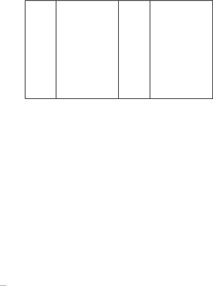
Battery |
Ground |
|
|
|
|
|
|
|
|
|
|
|
|
|
|
|
|
|
|
||||
Before completing any service on the motorcycle, |
|
|
|
|
|
||||||||||||||||||
nect the |
battery wires |
from |
the |
battery to |
|
prevent the |
|
|
|
|
|
||||||||||||
from |
accidentally |
turning over. Disconnect |
|
the |
ground |
|
|
|
|
|
|||||||||||||
(–) first |
and |
then |
the |
positive (+). |
When |
completed with |
|
|
|
|
|||||||||||||
service, |
first |
connect |
the positive (+) wire |
to |
the |
positive |
|
|
|
|
|||||||||||||
terminal |
of the |
battery |
|
then |
the |
negative (–) |
wire |
to |
|
|
|
|
|
||||||||||
ative |
terminal. |
|
|
|
|
|
|
|
|
|
|
|
|
|
|
|
|
|
|
|
|||
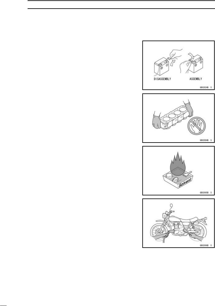
Edges |
of |
Parts |
|
|
|
|
|
|
|
|
|
|
|
|
|
|
|
|
|
|
|||
Lift large |
or |
heavy |
parts |
wearing |
gloves |
|
to |
prevent |
|
|
|
|
|
||||||||||
from |
possible |
sharp |
edges |
on |
the |
parts. |
|
|
|
|
|
|
|
|
|
||||||||
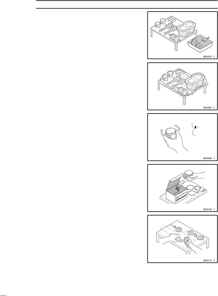
Solvent |
|
|
|
Use |
a high |
flush |
point solvent when cleaning parts |
flush |
point solvent |
should be used according to |
|
of the solvent |
manufacturer. |
||
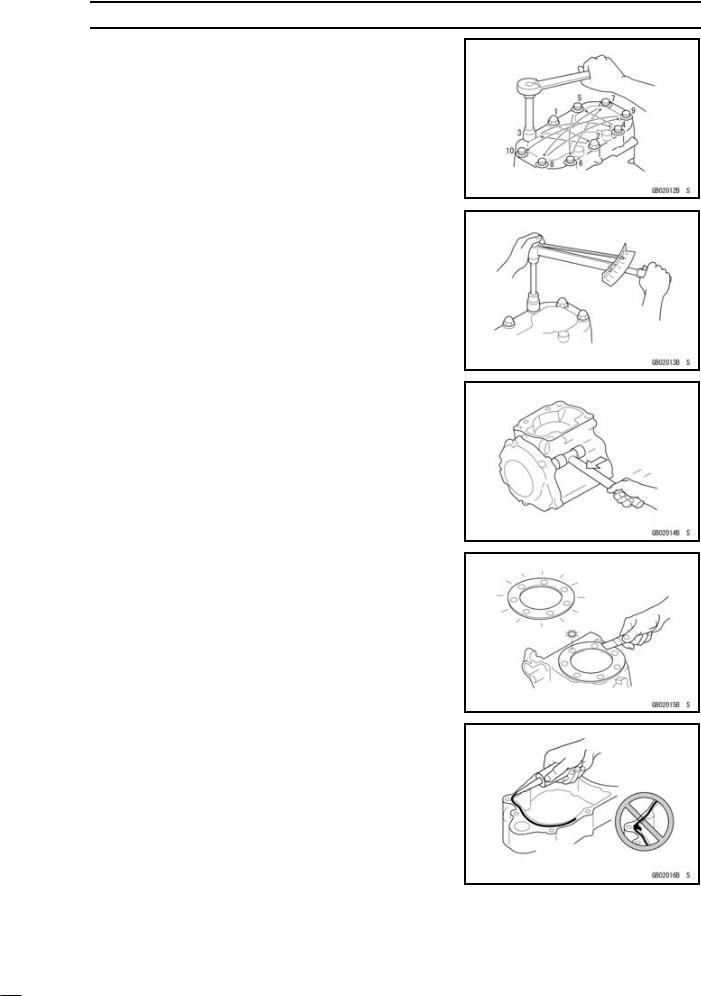
Cleaning vehicle before disassembly |
|
Clean the vehicle thoroughly before disassembly. Dirt |
|
other foreign |
materials entering into sealed areas during |
hicle disassembly can cause excessive wear and |
|
performance |
of the vehicle. |
|
|
|
|
|
|
|
|
GENERAL INFORMATION 1-3 |
Before Servicing |
|
|
|
|
|
|
||
Arrangement and Cleaning |
of |
Removed Parts |
||||||
Disassembled parts are easy to |
confuse. |
Arrange |
||||||
parts |
according |
to the |
order |
|
the |
parts were |
disassembled |
|
and |
clean the |
parts in |
order |
|
prior |
to assembly. |
||
Storage |
of Removed Parts |
|
|
||||
After all the |
parts including |
subassembly parts |
have |
|
|||
cleaned, |
store |
the |
parts |
in |
a clean area. |
Put a |
|
or plastic sheet over the parts to protect from |
any |
||||||
materials |
that |
may |
collect |
before re-assembly. |
|
||
Inspection |
|
|
||
Reuse |
of worn or damaged parts may lead to serious |
|||
cident. |
Visually inspect |
removed parts for corrosion, |
||
oration, |
or other damage. Refer to the appropriate |
|||
of this |
manual |
for service limits on individual parts. |
||
the |
parts if any damage has been found or if the part |
|||
yond |
its service limit. |
|
||
Replacement |
Parts |
|
||
Replacement Parts must be KAWASAKI genuine |
||||
recommended by KAWASAKI. Gaskets, O-rings, Oil |
||||
Grease |
seals, |
circlips |
or cotter pins must be replaced |
|
new |
ones whenever |
disassembled. |
||
Assembly Order |
|
|
|
||
In |
most cases |
assembly |
order |
is the reverse |
of |
bly, |
however, if assembly |
order is provided in |
this |
||
Manual, follow |
the procedures |
given. |
|
||
1-4 GENERAL INFORMATION
Before |
Servicing |
|
|
|
|
|
|
|
|||
Tightening |
Sequence |
|
|
|
|
|
|
|
|||
Bolts, nuts, or screws must be tightened according |
|||||||||||
specified sequence to prevent case |
warpage or |
deformation |
|||||||||
which can lead |
to |
malfunction. |
|
If |
|
the |
specified tightening |
||||
sequence is |
not indicated, |
tighten |
|
the fasteners |
alternating |
||||||
diagonally. |
|
|
|
|
|
|
|
|
|
|
|
Tightening |
Torque |
|
|
|
|
|
|
|
|
||
Incorrect |
|
torque |
applied |
to |
a |
|
bolt, |
nut, |
or screw |
||
lead to serious damage. Tighten fasteners to the |
|||||||||||
torque using a good quality torque wrench. |
|
||||||||||
Often, the tightening sequence is followed twice- |
|||||||||||
tightening |
and |
final |
tightening |
with |
torque wrench. |
||||||
Force |
|
|
|
|
|
|
|
|
|
|
|
|
|
|
|
|
|
|
|
Use common sense during disassembly and assembly, |
|||||||||||||||||||
excessive |
force |
can |
cause |
expensive or hard to repair |
|||||||||||||||
age. |
When |
necessary, |
|
remove |
screws |
|
that |
have |
|||||||||||
-permanent |
locking |
|
agent |
|
applied using |
an impact |
|
driver |
|||||||||||
Use a plastic-faced mallet whenever tapping is necessary |
|||||||||||||||||||
Gasket, |
O-ring |
|
|
|
|
|
|
|
|
|
|
|
|
|
|
|
|
||
Hardening, |
shrinkage, |
|
|
or |
damage |
of |
both |
|
|
|
|||||||||
and O-rings after disassembly can reduce sealing |
|||||||||||||||||||
formance. Remove old gaskets and clean the |
|
||||||||||||||||||
surfaces |
thoroughly |
so |
|
that |
no |
gasket |
material |
|
or |
||||||||||
material |
remains. |
|
|
Install |
|
new |
gaskets |
and |
replace |
||||||||||
O-rings when re-assembling |
|
|
|
|
|
|
|
|
|
||||||||||
Liquid |
Gasket, |
Locking |
|
Agent |
|
|
|
|
|
|
|
|
|||||||
For |
applications |
|
that |
require |
Liquid |
Gasket |
or |
|
a |
|
|||||||||
agent, |
clean |
the |
|
surfaces |
so |
that |
no |
oil residue |
remains |
||||||||||
fore applying liquid |
|
gasket |
or locking |
agent. Do |
not |
|
|||||||||||||
them excessively. Excessive application can clog oil |
|||||||||||||||||||
sages |
and |
cause |
|
serious |
damage. |
|
|
|
|
|
|
|
|||||||
GENERAL INFORMATION 1-5
Before Servicing
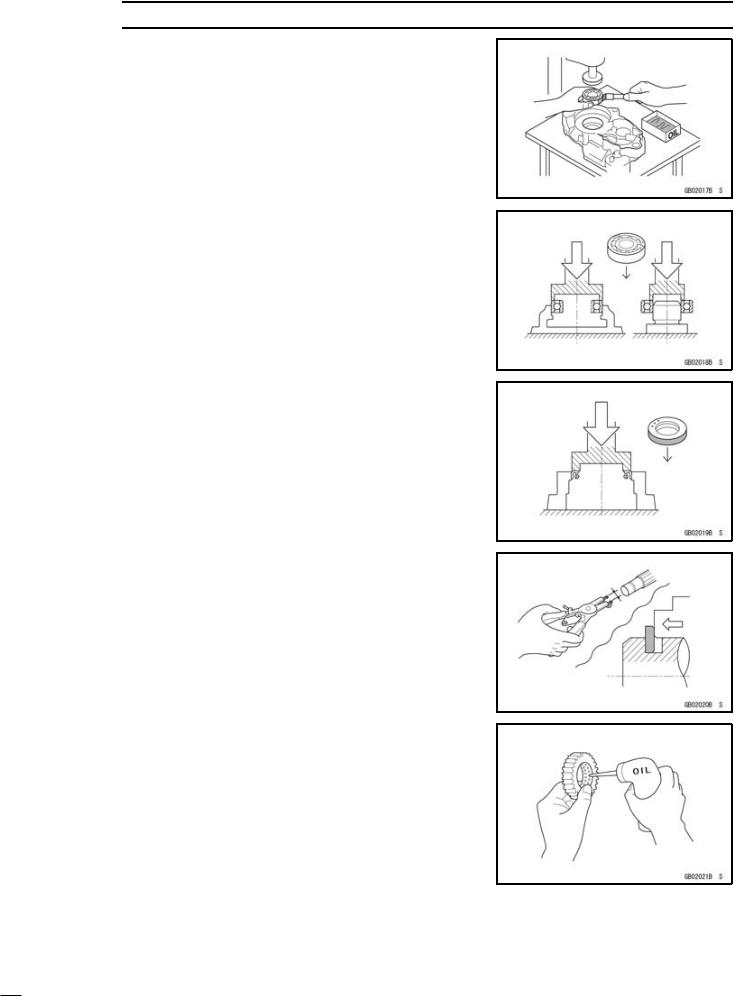
Press |
|
|
|
|
For |
items |
such |
as bearings or oil |
seals that |
pressed into |
place, |
apply small amount |
of oil to the |
|
tact area. Be sure to maintain proper alignment |
||||
smooth |
movements |
when installing. |
|
|
Ball Bearing |
and |
Needle |
Bearing |
|
|
|
Do not remove pressed ball or needle unless |
||||||
absolutely necessary. Replace with new ones whenever |
||||||
removed. Press bearings with the manufacturer and |
||||||
marks facing |
out. Press |
the |
bearing into |
place |
by |
|
pressure on the correct bearing race as shown. |
||||||
Pressing the incorrect race |
can cause |
pressure between |
||||
the inner and |
outer |
race |
and result in bearing |
damage |
||
Oil Seal, |
Grease |
Seal |
|
|
Do |
not remove pressed oil or grease seals unless |
|||
is necessary. Replace with new ones whenever |
||||
Press |
new oil seals |
with manufacture |
and size marks |
|
out. |
Make |
sure the seal is aligned |
properly when |
|
Circlips, Cotter |
Pins |
|
|
|
|
|
|
|
|
|
||||||
Replace circlips or cotter pins that were removed with |
||||||||||||||||
ones. Install |
the |
circlip |
with its sharp |
edge |
facing |
|
||||||||||
and its |
chamfered |
side |
facing inward to |
prevent |
the |
clip |
||||||||||
being |
pushed |
|
out |
of |
its |
groove |
when |
loaded. |
Take |
|||||||
not |
to |
open |
|
the |
|
clip excessively |
when installing |
to |
|
|||||||
deformation. |
|
|
|
|
|
|
|
|
|
|
|
|
|
|
||
Lubrication |
|
|
|
|
|
|
|
|
|
|
|
|
|
|
||
It is important |
|
to lubricate |
rotating |
or |
sliding |
parts |
|
|||||||||
assembly to |
minimize wear |
during initial |
operation. |
Lubri |
||||||||||||
cation |
points |
|
are |
|
called out |
throughout |
this |
manual, |
||||||||
the |
specific |
oil |
or |
grease |
as |
specified. |
|
|
|
|
||||||
1-6 GENERAL INFORMATION
Before |
Servicing |
|
|
|
|
||
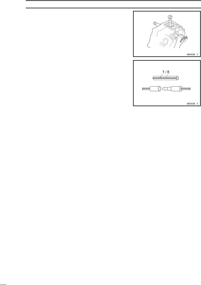
Direction |
of |
Engine |
Rotation |
|
|
|
|
When |
rotating the |
crankshaft |
by |
hand, |
the free |
||
amount of rotating direction will |
affect |
the |
adjustment |
||||
tate |
the |
crankshaft to positive direction (clockwise |
|||||
from |
output |
side). |
|
|
|
|
|
Electrical Wires |
|
|
|
|
|
A two-color wire is identified first by |
the |
primary color |
|||
then |
the stripe |
color. Unless instructed |
otherwise, |
electrical |
|
wires |
must be |
connected to those |
of |
the same |
color |
GENERAL INFORMATION 1-7
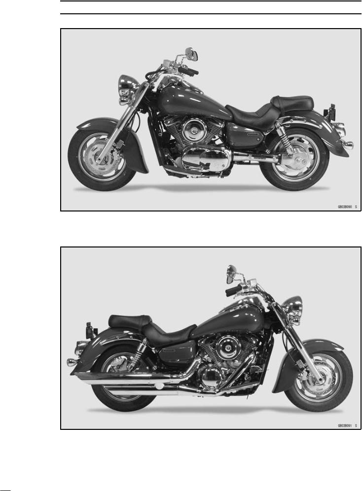
Model Identification
VN1600-A1 (US, and Canada) Left Side View:
VN1600-A1 (US, and Canada) Right Side View:

1-8 GENERAL INFORMATION
Model Identification
VN1600-A1 (Europe) Left Side View:
VN1600-A1 (Europe) Right Side View:

|
|
|
|
|
|
|
|
|
|
|
|
|
GENERAL |
INFORMATION |
1-9 |
|||||
General |
Specifications |
|
|
|
|
|
|
|
|
|
|
|
|
|
|
|
|
|||
Dimensions: |
Items |
|
|
|
|
|
|
|
|
|
VN1600-A1 |
|
|
|
|
|||||
|
|
|
|
|
|
|
|
|
|
|
|
|
|
|
|
|
||||
Overall |
length |
2 |
505 |
|
mm |
|
(98.62 |
in.) |
|
|
|
|
|
|
||||||
Overall |
width |
1 |
040 |
|
mm |
(40.9 |
in.), |
(AU) |
990 mm |
(39 |
in.) |
|
||||||||
Overall |
height |
1 |
130 |
|
mm |
|
(44.5 |
in.) |
|
|
|
|
|
|
||||||
Wheelbase |
|
1 680 mm (66.1 in.) |
|
|
|
|
|
|
||||||||||||
Road |
clearance |
130 |
mm |
(5.12 |
in.) |
|
|
|
|
|
|
|||||||||
Seat |
height |
|
680 |
mm |
(26.8 |
in.) |
|
|
|
|
|
|
||||||||
Dry mass |
|
|
306 |
kg |
|
(675 |
lb), |
(AU) |
307 |
kg |
(677 |
lb) |
|
|
||||||
Curb |
mass: |
Front |
156 |
kg |
|
(345 |
lb) |
|
|
|
|
|
|
|
||||||
|
|
|
|
Rear |
181 |
kg |
|
(399 |
lb), |
(AU) |
182 |
kg |
(401 |
lb) |
|
|
||||
Fuel |
tank |
capacity |
20 L (5.3 US gal) |
|
|
|
|
|
|
|||||||||||
Fuel |
|
|
|
|
Unleaded and high-octane gasoline |
|
|
|
||||||||||||
Performance: |
|
(see |
|
VN1600-A1 |
Owner’s Manual) |
|
|
|
||||||||||||
|
|
|
|
|
|
|
|
|
|
|
|
|
|
|
|
|
||||
Minimum |
turning radius |
3.5 |
|
m |
|
(11.5 |
ft) |
|
|
|
|
|
|
|
|
|||||
Engine: |
|
|
|
|
|
|
|
|
|
|
|
|
|
|
|
|
|
|
|
|
Type |
|
|
|
|
4-stroke, SOHC, V2-cylinder |
|
|
|
|
|
||||||||||
Cooling |
system |
Liquid-cooled |
|
|
|
|
|
|
|
|
|
|||||||||
Bore |
and |
stroke |
102 |
× |
|
95 |
mm |
(4.02 |
× 3.74 in.) |
|
|
|
||||||||
Displacement |
|
1 |
552 |
|
mL |
(94.70 |
cu |
in.) |
|
|
|
|
|
|||||||
Compression |
ratio |
9.0 |
|
: |
1 |
|
|
|
|
|
|
|
|
|
|
|
||||
Maximum |
horsepower |
49 |
|
kW |
(67 |
|
PS) @ 4 700 r/min |
(rpm), |
(CA) (CAL) (US) – |
|||||||||||
Maximum |
torque |
127 |
N·m |
(12.95 |
kgf·m, |
93.7 |
ft·lb) @ 2 |
700 |
r/min |
(rpm), |
||||||||||
|
|
|
|
|
(CA) |
|
(CAL) |
(US) |
– |
|
|
|
|
|
|
|||||
Carburetion |
system |
DFI (Digital Fuel Injection) System |
|
|
|
|||||||||||||||
Starting |
system |
Electric |
starter |
|
|
|
|
|
|
|
|
|||||||||
Ignition |
system |
Battery |
and |
|
coil |
(transistorized) |
|
|
|
|
||||||||||
Timing |
advance |
Electronically |
|
advanced |
(digital) |
|
|
|
|
|||||||||||
Ignition |
timing |
From |
0° |
BTDC |
@ 950 |
r/min |
(rpm)25° BTDC |
@ 4 |
500 |
|||||||||||
|
|
|
|
|
r/min |
(rpm) |
|
|
|
|
|
|
|
|
|
|
||||
Spark |
plugs |
|
NGK DPR6EA-9 or ND X20EPR-U9 |
|
|
|
||||||||||||||
Cylinder |
numbering method |
Front |
to |
Rear, |
1-2 |
|
|
|
|
|
|
|||||||||
Firing |
order |
|
1-2 |
|
|
|
|
|
|
|
|
|
|
|
|
|
|
|||
Valve |
timing: |
|
|
|
|
|
|
|
|
|
|
|
|
|
|
|
|
|||
Inlet |
|
|
|
Open |
22° |
BTDC |
|
|
|
|
|
|
|
|
|
|
||||
|
|
|
|
Close |
66° |
ABDC |
|
|
|
|
|
|
|
|
|
|
||||
|
|
|
|
Duration |
268° |
|
|
|
|
|
|
|
|
|
|
|
|
|
||
Exhaust |
|
Open |
66° |
BBDC |
|
|
|
|
|
|
|
|
|
|
||||||
|
|
|
|
Close |
26° |
ATDC |
|
|
|
|
|
|
|
|
|
|
||||
|
|
|
|
Duration |
272° |
|
|
|
|
|
|
|
|
|
|
|
|
|
||
Lubrication |
system |
Forced |
lubrication |
(wet |
sump) |
|
|
|
|
|||||||||||
Engine |
oil: |
Type |
API SE, SF or SG class |
|
|
|
|
|
||||||||||||
|
|
|
|
|
API SH or SJ class with JASO MA |
|
|
|
||||||||||||
|
|
|
|
Viscosity |
SAE10W-40 |
|
|
|
|
|
|
|
|
|
|
|||||
|
|
|
|
Capacity |
3.5 |
|
L |
|
(3.7US qt, |
when engine |
is completely disassembled |
|||||||||
|
|
|
|
|
and |
dry) |
|
|
|
|
|
|
|
|
|
|
|
|||

1-10 GENERAL INFORMATION
General |
Specifications |
|
|
|
|
|
|
|
|
|||||
Drive |
Train: |
Items |
|
|
|
|
|
|
|
VN1600-A1 |
||||
|
|
|
|
|
|
|
|
|
|
|
||||
Primary |
reduction |
system: |
|
|
|
|
|
|
|
|
||||
Type |
|
|
|
|
|
Gear |
|
|
|
|
|
|||
Reduction |
ratio |
|
|
1.517 |
(85/56) |
|
|
|||||||
Clutch |
type |
|
|
|
|
Wet |
multi |
disc |
|
|||||
Transmission: |
|
|
|
|
|
|
|
|
|
|
||||
Type |
|
|
|
|
|
5-speed, constant mesh, return shift |
||||||||
Gear ratios: |
|
1st |
|
2.500 |
(40/16) |
|
||||||||
|
|
|
|
|
|
2nd |
|
1.590 |
(35/22) |
|
||||
|
|
|
|
|
|
3rd |
|
1.192 |
(31/26) |
|
||||
|
|
|
|
|
|
4th |
|
0.965 |
(28/29) |
|
||||
Final |
drive |
system: 5th |
|
0.781 |
(25/32) |
|
||||||||
Type |
|
|
|
|
|
Shaft |
|
|
|
|
|
|||
Reduction |
ratio |
|
|
2.619 |
(15/21 |
× |
33/9) |
|||||||
Overall |
drive |
ratio |
|
3.105 |
@ Top |
gear |
||||||||
Final |
gear |
case |
oil: |
|
|
|
|
|
|
|
|
|||
Grade |
|
|
|
|
|
API Service Classification: GL-5 Hypoid gear oil |
||||||||
Viscosity |
|
|
|
|
SAE90 (above 5°C), SAE80 (below 5°C) |
|||||||||
Capacity |
|
|
|
|
200 |
mL |
|
(6.76 |
US oz) |
|||||
Frame: |
|
|
|
|
|
|
|
|
|
|
|
|
|
|
Type |
|
|
|
|
|
|
Tubular, |
double |
cradle |
|||||
Caster |
(rake angel) |
|
32° |
|
|
|
|
|
|
|||||
Trail |
|
|
|
|
|
|
|
168 mm |
(6.61 |
in.) |
||||
Front |
tire: |
|
|
Type |
|
Tubeless |
|
|
|
|
||||
|
|
|
|
|
|
Size |
|
130/90 - 16 M/C 67H |
||||||
Rear |
tire: |
|
|
Type |
|
Tubeless |
|
|
|
|
||||
|
|
|
|
|
|
Size |
|
170/70B16 M/C |
75H |
|||||
Front |
suspension: |
Type |
|
Telescopic |
fork |
|
||||||||
|
|
|
|
|
|
Wheel |
travel |
150 |
mm |
|
(5.91 |
in.) |
||
Rear |
suspension: |
Type |
|
Swingarm |
|
|
|
|
||||||
|
|
|
|
|
|
Wheel |
travel |
95 |
mm |
(3.74 |
in.) |
|||
Brake |
Type: |
|
Front |
|
Dual |
disc |
|
|
|
|||||
Electrical |
Equipment:Rear |
|
Single |
disc |
|
|
||||||||
Battery |
|
|
|
Capacity |
12 |
V |
18 |
Ah |
|
|||||
Headlight: |
|
|
Type |
|
Semi-sealed |
beam |
||||||||
|
|
|
|
|
|
Bulb |
|
12 |
V |
60/55 W (quartz-halogen) |
||||
Tail/brake |
light |
|
|
|
12 |
V |
5/21 |
W |
|
|||||
Alternator: |
|
|
Type |
|
Three-phase AC, twin rotor |
|||||||||
|
|
|
|
|
|
Rated |
output |
42A × 14 V @ 6 000 r/min (rpm) |
||||||
Specifications |
are |
subject to |
change without |
|
notice, and may not apply to every country. |
|||||||||
AU: |
Australia |
|
|
|
|
|
|
|
|
|
|
|||
CAL: |
California |
|
|
|
|
|
|
|
|
|
|
|||
CA: |
Canada |
|
|
|
|
|
|
|
|
|
|
|
||
US: |
United |
States |
of America |
|
|
|
|
|
|
|
||||
Unit Conversion Table |
|
|
|
||
Prefixes |
for Units: |
|
|
|
|
Prefix |
Symbol |
|
Power |
|
|
mega |
M |
× 1 |
000 |
000 |
|
kilo |
k |
× |
1 |
000 |
|
centi |
c |
× |
0.01 |
|
|
milli |
m |
× |
0.001 |
|
|
micro |
µ |
× 0.000001 |
|||
Units |
of |
Mass: |
|
|
|
kg |
× |
2.205 |
= |
lb |
|
g |
× |
0.03527 |
= |
oz |
|
Units |
of |
Volume: |
|
|
|
L |
× |
0.2642 |
= |
gal |
(US) |
L |
× |
0.2200 |
= |
gal |
(imp) |
L |
× |
1.057 |
= |
qt |
(US) |
L |
× |
0.8799 |
= |
qt |
(imp) |
L |
× |
2.113 |
= |
pint |
(US) |
L |
× |
1.816 |
= |
pint |
(imp) |
mL |
× |
0.03381 |
= |
oz |
(US) |
mL |
× |
0.02816 |
= |
oz |
(imp) |
mL |
× |
0.06102 |
= |
cu |
in. |
Units |
of |
Force: |
|
|
|
N |
× |
0.1020 |
= |
kgf |
|
N |
× |
0.2248 |
= |
lb |
|
kg |
× |
9.807 |
= |
N |
|
kg |
× |
2.205 |
= |
lb |
|
Units of Temperature:
GENERAL INFORMATION 1-11
Units |
of |
Length: |
|
|
km |
× |
0.6214 |
= |
mile |
m |
× |
3.281 |
= |
ft |
mm |
× |
0.03937 |
= |
in. |
Units |
of Torque: |
|
|
|
N·m |
× |
0.1020 |
= |
kgf·m |
N·m |
× |
0.7376 |
= |
ft·lb |
N·m |
× |
8.851 |
= |
in·lb |
kgf·m |
× |
9.807 |
= |
N·m |
kgf·m |
× |
7.233 |
= |
ft·lb |
kgf·m |
× |
86.80 |
= |
in·lb |
Units |
of |
Pressure: |
|
|
kPa |
× |
0.01020 |
= |
kgf/cm² |
kPa |
× |
0.1450 |
= |
psi |
kPa |
× |
0.7501 |
= |
cm Hg |
kgf/cm² |
× |
98.07 |
= |
kPa |
kgf/cm² |
× |
14.22 |
= |
psi |
cm Hg |
× |
1.333 |
= |
kPa |
Units |
of |
Speed: |
|
|
km/h |
× |
0.6214 |
= |
mph |
Units |
of |
Power: |
|
|
kW |
× |
1.360 |
= |
PS |
kW |
× |
1.341 |
= |
HP |
PS |
× |
0.7355 |
= |
kW |
PS |
× |
0.9863 |
= |
HP |


PERIODIC MAINTENANCE 2-1
Periodic Maintenance
Table of Contents |
2 |
|
Periodic |
|
Maintenance |
Chart .............. |
2-2 |
||||||
Torque |
|
and |
|
|
Locking |
Agent................. |
2-4 |
|||
Specifications |
.................................... |
|
|
|
2-10 |
|||||
Special Tools |
..................................... |
|
|
|
|
2-12 |
||||
Periodic |
|
Maintenance |
Procedures..... |
2-13 |
||||||
Fuel System (DFI)........................... |
|
|
2-13 |
|||||||
Fuel |
|
|
Hose |
and |
Connection |
|
||||
Inspection.................................. |
|
|
|
2-13 |
||||||
Throttle |
Control System |
|
||||||||
Inspection.................................. |
|
|
|
2-13 |
||||||
Idle |
|
Speed |
Inspection .................. |
2-14 |
||||||
Air |
Cleaner |
Element |
Cleaning...... |
2-15 |
||||||
Evaporative |
Emission |
Control |
|
|||||||
System |
|
|
Inspection (CAL) .......... |
2-15 |
||||||
Cooling System............................... |
|
|
2-16 |
|||||||
Radiator |
|
|
Hose and |
Connection |
|
|||||
Inspection.................................. |
|
|
|
2-16 |
||||||
Coolant |
Change ........................... |
|
|
2-17 |
||||||
Engine |
Top End.............................. |
|
|
2-19 |
||||||
Air |
Suction |
Valve |
Inspection ........ |
2-19 |
||||||
Clutch.............................................. |
|
|
|
|
|
|
|
|
2-19 |
|
Clutch |
Hose and |
Connection |
|
|||||||
Inspection.................................. |
|
|
|
2-19 |
||||||
Clutch |
Fluid |
Level Inspection ....... |
2-20 |
|||||||
Clutch |
Fluid |
Change |
.................... |
2-20 |
||||||
Clutch Master Cylinder Cup and |
|
|||||||||
Dust |
Seal |
Replacement ............ |
2-21 |
|||||||
Clutch Slave Cylinder Piston Seal |
|
|||||||||
Replacement ............................ |
|
|
2-22 |
|||||||
Engine |
Lubrication |
System ............. |
2-23 |
|||||||
Engine Oil |
Change....................... |
|
2-23 |
|||||||
Oil Filter |
|
Replacement................. |
2-24 |
|||||||
Wheel/Tires |
..................................... |
|
|
|
|
2-24 |
||||
Tire |
|
Inspection............................. |
|
|
2-24 |
|||||
Final Drive....................................... |
|
|
|
|
2-25 |
|
Oil Level Inspection...................... |
|
2-25 |
||||
Oil Change................................... |
|
|
|
2-26 |
||
Propeller |
Shaft Joint Lubrication.. |
2-26 |
||||
Brakes............................................. |
|
|
|
|
|
2-27 |
Brake |
Pad |
Wear |
Inspection......... |
2-27 |
||
Brake |
Hose |
|
and |
Connection |
|
|
Inspection.................................. |
|
|
|
2-27 |
||
Brake |
Fluid |
Level |
Inspection........ |
2-27 |
||
Brake |
Fluid |
Change..................... |
2-28 |
|||
Brake Master Cylinder Cup and |
|
|||||
Dust |
Seal |
Replacement............ |
2-29 |
|||
Caliper Piston/Dust |
Seals |
|
||||
Replacement |
............................. |
|
2-29 |
|||
Front |
Brake |
|
Light |
Switch |
|
|
Inspection.................................. |
|
|
|
2-29 |
||
Rear |
Brake |
Light |
itchSw |
|
||
Check/Adjustment ..................... |
|
2-30 |
||||
Suspension |
..................................... |
|
|
|
2-30 |
|
Front Fork Oil Leak Inspection..... |
2-30 |
|||||
Rear |
Shock |
Absorber l OiLeak |
|
|||
Inspection ................................. |
|
|
|
2-31 |
||
Swingarm |
Pivot Lubrication......... |
2-31 |
||||
Steering |
.......................................... |
|
|
|
|
2-31 |
Stem |
Bearing Lubrication............. |
2-31 |
||||
Steering |
Check............................ |
|
2-31 |
|||
Steering |
Adjustment..................... |
2-32 |
||||
Electrical System ............................ |
|
2-33 |
||||
Spark |
Plug Cleaning/Inspection... |
2-33 |
||||
General |
Lubrication........................ |
|
2-33 |
|||
Lubrication ................................... |
|
|
|
2-33 |
||
Nut, Bolt, and Fastener Tightness.. |
2-34 |
|||||
Tightness |
Inspection.................... |
2-34 |
||||
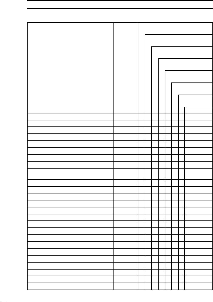
2-2 PERIODIC MAINTENANCE
Periodic Maintenance Chart |
|
|
|
|
The scheduled maintenance must be done in accordance |
with |
this chart to keep the motorcycle in |
||
good running conditionThe. initial maintenance is vitally important and must not be neglected. |
||||
FREQUENCY Whichever |
1 000 km |
* ODOMETER |
||
comes |
(600 |
mile) |
|
READING |
first |
6 |
000 |
km |
|
→ |
(4 |
000 |
mile) |
|
↓ |
|
12 |
000 |
km |
|
|
(7 |
500 |
mile) |
|
|
|
|
|
|
|
|
|
|
|
|
|
|
|
|
|
|
18 000 |
km |
|
|
||
|
|
|
|
|
|
|
|
|
|
|
|
|
|
|
|
|
|
(12 |
000 |
mile) |
|
||
|
|
|
|
|
|
|
|
|
|
|
|
|
|
|
|
|
|
|
24 |
000 km |
|
||
|
|
|
|
|
|
|
|
|
|
|
|
|
|
|
|
|
|
|
(15 |
000 |
mile) |
|
|
|
|
|
|
|
|
|
|
|
|
|
|
|
|
|
|
|
|
|
|
30 000 |
km |
|
|
|
|
|
|
|
|
|
|
|
|
|
|
|
|
|
|
|
|
|
|
(20 |
000 mile) |
||
|
|
|
|
|
|
|
|
|
|
|
|
|
|
|
|
|
|
|
|
36 |
000 |
km |
|
|
|
|
|
|
|
|
|
|
|
|
|
|
|
|
|
|
|
|
|
(24 |
000 |
mile) |
|
OPERATION |
|
|
|
|
|
|
|
|
Every |
|
• • • • • |
• |
See Page |
||||||||||
Spark |
plug (e) |
- clean and |
gap † |
|
|
|
|
2–35 |
|||||||||||||||
Air |
suction |
valve (e) |
- inspect |
† |
|
|
|
• • • • • |
• |
|
2–20 |
||||||||||||
Air |
cleaner |
element |
(e) |
- clean†# |
|
|
|
|
• |
|
• |
|
• |
|
2–16 |
||||||||
|
|
|
|
|
|
|
|
|
|
|
|
|
|
|
|
|
|
|
|
|
|||
Throttle |
control |
system (e) |
- inspect |
† |
• |
• |
• |
• |
• |
• |
• |
|
2–14 |
||||||||||
|
|
|
|
|
|
|
|
|
|
|
|
|
|
|
|
|
|||||||
Idle |
speed |
(e) |
- inspect |
† |
|
|
|
|
• |
|
• |
|
• |
|
• |
|
2–15 |
||||||
Fuel |
|
hoses, connections |
- inspect |
† |
|
|
• |
• |
• |
• |
• |
• |
|
2–14 |
|||||||||
Engine |
oil |
- change |
# |
|
|
|
|
year |
• |
|
• |
|
• |
|
• |
|
2–24 |
||||||
Oil filter |
- replace |
|
|
|
|
|
|
|
|
• |
|
• |
|
• |
|
• |
|
2–26 |
|||||
Evaporative |
emission |
control |
system |
(e) |
|
|
|
|
|
|
|||||||||||||
• |
• |
• |
• |
• |
• |
• |
|
2–17 |
|||||||||||||||
(CAL) |
- inspect |
† |
|
|
|
|
|
|
|
|
|
||||||||||||
|
|
|
|
|
|
|
|
|
|
|
|||||||||||||
Final |
gear |
case |
oil level |
- inspect |
† |
|
|
|
• |
|
• |
|
• |
|
2–28 |
||||||||
Final |
gear |
case |
oil |
- change |
|
|
|
• |
|
|
|
|
|
• |
|
2–28 |
|||||||
Propeller shaft joint |
- lubricate |
|
|
|
|
|
• |
|
|
|
• |
|
2–29 |
||||||||||
|
|
|
|
|
|
|
|
|
|
|
|
|
|
|
|
|
|
|
|
|
|
||
Brake |
pad |
wear |
- inspect |
† |
# |
|
|
|
• • • • • • |
|
2–29 |
||||||||||||
Brake light |
switch |
- inspect |
† |
|
|
|
• |
• • • • • • |
|
2–32 |
|||||||||||||
Steering |
- inspect |
† |
|
|
|
|
|
|
• • • • • • • |
|
2–34 |
||||||||||||
Rear |
shock absorber |
oil leak |
- inspect † |
|
|
• |
|
• |
|
• |
|
2–33 |
|||||||||||
|
|
|
|
|
|
|
|
|
|
|
|
|
|
|
|
|
|
|
|
|
|||
Front |
fork |
oil leak |
- inspect |
† |
|
|
|
|
|
• |
|
• |
|
• |
|
2–33 |
|||||||
|
|
|
|
|
|
|
|
|
|
|
|
|
|
|
|
|
|
|
|
|
|||
Tire |
wear |
- inspect |
† |
|
|
|
|
|
|
• • • • • • |
|
2–27 |
|||||||||||
Swingarm pivot |
- lubricate |
|
|
|
|
|
|
• |
|
|
|
• |
|
2–33 |
|||||||||
General |
lubrication |
- perform |
|
|
|
|
|
• |
|
• |
|
• |
|
2–36 |
|||||||||
Nut, |
|
bolt, and |
fastener |
tightness |
- inspect † |
• |
• |
• |
• |
• |
• |
• |
|
2–37 |
|||||||||
|
|
|
|
|
|
|
|
|
|
|
|
|
|
|
|
|
|||||||
Brake/clutch |
hoses, connections - inspect † |
• |
• |
• |
• |
2–21, |
2–29 |
||||||||||||||||
Brake/clutch |
fluid level |
- inspect † |
|
month |
• |
• |
• |
• |
• |
• |
2–21, |
2–29 |
|||||||||||
Coolant hoses, connections - inspect † |
• |
|
|
|
• |
|
|
|
2–18 |
||||||||||||||
Brake/clutch |
fluid |
- change |
|
|
|
2 years |
|
|
|
|
|
2–22, |
2–30 |
||||||||||
|
|
|
|
|
|
|
|
|
|
|
|
|
|
|
|
|
|
|
|
|
|
|
|
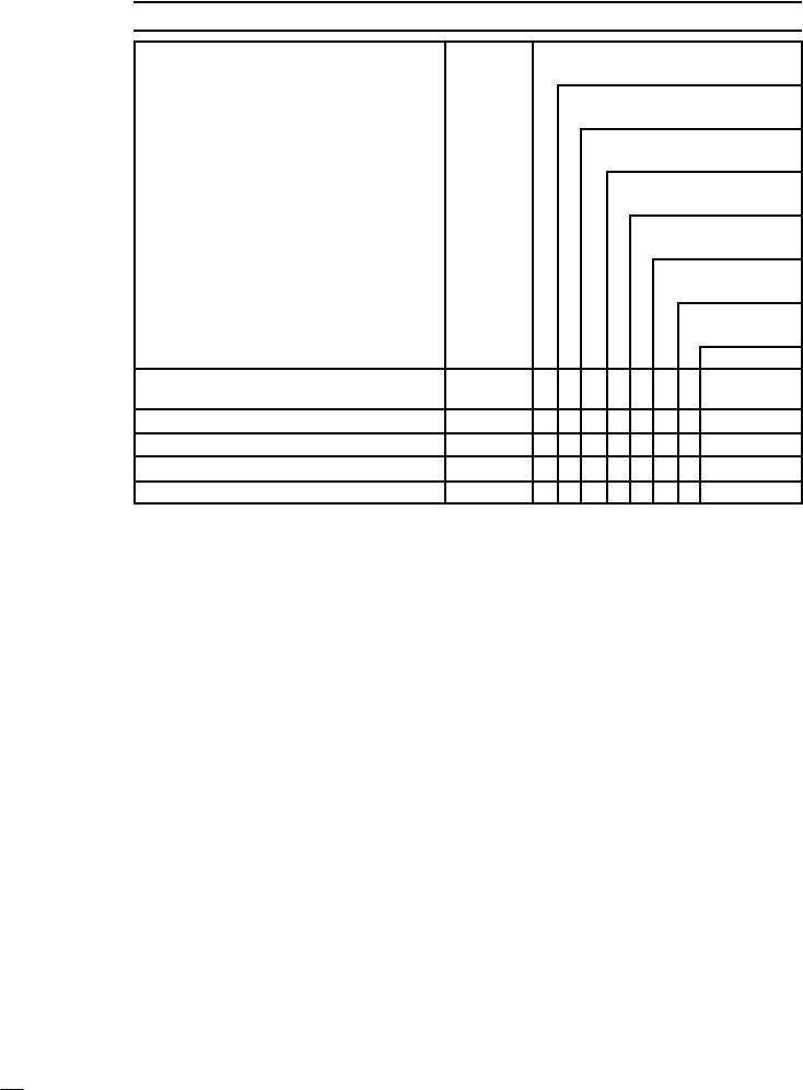
|
PERIODIC |
MAINTENANCE 2-3 |
|||
Periodic Maintenance Chart |
|
|
|
|
|
FREQUENCY Whichever |
1 000 km |
|
* ODOMETER |
||
comes |
(600 |
mile) |
|
READING |
|
first |
6 |
000 |
|
km |
|
→ |
(4 |
000 |
|
mile) |
|
↓ |
|
12 |
|
000 |
km |
|
|
(7 |
500 |
mile) |
|
|
|
|
|
|
|
|
|
|
|
|
|
18 |
000 |
km |
|
|
|
||
|
|
|
|
|
|
|
|
|
|
|
|
(12 |
000 |
mile) |
|
|
|||
|
|
|
|
|
|
|
|
|
|
|
|
|
24 |
000 |
km |
|
|
||
|
|
|
|
|
|
|
|
|
|
|
|
|
(15 |
000 |
mile) |
|
|||
|
|
|
|
|
|
|
|
|
|
|
|
|
|
30 |
000 km |
||||
|
|
|
|
|
|
|
|
|
|
|
|
|
|
(20 |
000 |
mile) |
|||
|
|
|
|
|
|
|
|
|
|
|
|
|
|
|
36 |
000 |
km |
||
|
|
|
|
|
|
|
|
|
|
|
|
|
|
|
(24 |
000 |
mile) |
||
OPERATION |
|
|
|
|
|
|
Every |
|
|
|
|
See |
Page |
||||||
Brake/clutch |
master |
cylinder cup |
and dust |
4 |
years |
|
|
|
|
2–23, |
2–32 |
||||||||
seal |
- replace |
|
|
|
|
|
|
|
|
• |
|
|
|
|
|
|
|
||
Coolant |
- change |
|
|
|
|
2 |
years |
|
|
|
|
2–28 |
|||||||
|
|
|
|
|
|
|
|
|
|||||||||||
Caliper |
piston |
seal |
and |
dust |
seal - replace4 |
years |
• |
|
|
|
|
2–32 |
|||||||
Steering stem bearing - lubricate |
|
2 |
years |
|
|
|
|
2–34 |
|||||||||||
|
|
|
|
|
|
||||||||||||||
Clutch |
slave cylinder piston seal - replace |
4 |
years |
|
|
|
|
|
2–24 |
||||||||||
# |
: |
Service |
more |
frequentlywhen operating in |
|
severe |
conditions; dusty, |
wet, |
muddy, |
high speed or |
|||||||||
|
frequent |
starting/stopping. |
|
|
|
|
|
|
|
|
|
|
|
|
|||||
* : |
|
For higher odometer readings, repeat |
|
at the |
frequency interval |
established |
here. |
||||||||||||
† : |
|
Replace, |
add, |
adjust,clean, |
or |
torque if |
necessary. |
|
|
|
|
|
|
|
|||||
Throttle |
control system inspection: |
Inspection |
of throttle grip play and throttle |
bore |
cleanliness. |
||||||||||||||
(CAL): |
California |
|
|
|
|
|
|
|
|
|
|
|
|
|
|
||||
(e): |
|
Emission |
Related |
Items |
|
|
|
|
|
|
|
|
|
|
|
|
|||
2-4 PERIODIC MAINTENANCE
Torque |
and |
Locking |
Agent |
|
|
|
|
|
|
|
|
|
|
|
|
|
|
|
|
|
|
|||||||||||
The |
following |
tables |
|
list |
the |
tightening |
torque The |
table below, relating tightening torque to |
||||||||||||||||||||||||
for the |
major |
fasteners |
requiring |
use |
of a |
nonthread |
diameter, |
lists the basic |
torque for |
the |
||||||||||||||||||||||
-permanent |
|
locking |
agent |
or liquid |
gasket. |
|
|
bolts |
and nuts. Use this table for |
only the |
bolts |
|||||||||||||||||||||
|
|
|
|
|
|
|
|
|
|
|
|
|
|
|
|
|
|
|
|
and |
nuts which do not require a specific torque |
|||||||||||
Letters |
used in |
the |
“Remarks” |
column mean: |
value. |
All |
of |
the values are for use with dry |
||||||||||||||||||||||||
L: Apply a |
non-permanent locking |
|
agent |
to |
solvent-cleaned |
threads. |
|
|
|
|
|
|
||||||||||||||||||||
the |
threads. |
|
to |
|
the |
threads. |
|
|
|
|
|
Basic Torque |
for |
General |
Fasteners |
|
||||||||||||||||
G: Apply |
|
grease |
|
|
|
|
|
|
Threads |
|
|
|
Torque |
|
|
|
|
|||||||||||||||
MO: Apply |
|
molybdenum |
|
disulfide |
grease |
oil |
|
|
|
|
|
|
|
|||||||||||||||||||
|
|
dia. |
(mm) |
N·m |
|
kgf·m |
|
ft·lb |
|
|||||||||||||||||||||||
solution. |
|
|
|
|
|
|
|
|
|
|
|
|
|
|
|
|
|
|
||||||||||||||
O: Apply |
|
oil |
to |
|
the |
threads |
and |
seating |
sur |
5 |
3.4 |
4.9 |
0.35 |
|
0.50 |
30 |
43 in·lb |
|
||||||||||||||
face. |
|
|
|
|
|
|
|
|
|
|
|
|
|
|
|
|
|
|
6 |
5.9 |
7.8 |
0.60 |
|
0.80 |
52 |
69 in·lb |
|
|||||
S: Tighten |
|
the |
fasteners following |
the |
speci |
|
|
|||||||||||||||||||||||||
|
|
8 |
|
14 19 |
|
1.4 1.9 |
10.0 |
13.5 |
|
|||||||||||||||||||||||
fied |
sequence. |
|
|
|
|
|
|
|
|
|
|
|
|
|
|
|
||||||||||||||||
|
|
|
|
|
|
|
|
|
|
|
10 |
|
25 |
34 |
|
2.6 |
3.5 |
19.0 |
25 |
|
||||||||||||
SS: Apply silicone |
|
sealant. |
|
|
|
|
|
|
|
|
|
|
||||||||||||||||||||
Si: Apply silicone |
|
grease (ex. |
|
PBC |
|
grease). |
12 |
|
44 |
61 |
|
4.5 |
6.2 |
33 |
45 |
|
||||||||||||||||
R: Replacement |
|
parts |
|
|
|
|
|
|
|
|
|
14 |
|
73 |
98 |
|
7.4 |
10.0 |
54 |
72 |
|
|||||||||||
Lh: Left-hand-threads |
|
|
|
|
|
|
|
|
|
|
|
16 |
115 |
155 11.5 |
16.0 |
83 115 |
|
|||||||||||||||
St: Stake |
|
the |
fasteners |
to |
prevent loosening. |
|
||||||||||||||||||||||||||
|
18 |
165 |
225 |
17.0 |
|
23.0 |
125 |
165 |
|
|||||||||||||||||||||||
AL: Tighten |
|
the |
|
two |
clamp |
|
bolts |
alternately |
|
|||||||||||||||||||||||
two |
times |
to |
|
ensure |
|
even |
tightening |
20 |
225 |
325 |
23 |
33 |
165 |
240 |
|
|||||||||||||||||
torque. |
|
|
|
|
|
|
|
|
|
|
|
|
|
|
|
|
|
|
|
|
|
|
|
|
|
|
|
|
|
|
||
|
|
|
|
|
|
Fastener |
|
|
|
|
|
|
|
|
|
|
|
Torque |
|
|
|
|
Remarks |
|
||||||||
|
|
|
|
|
|
|
|
|
|
|
|
|
N·m |
|
kgf·m |
ft·lb |
|
|
||||||||||||||
|
|
|
|
|
|
|
|
|
|
|
|
|
|
|
|
|
|
|
|
|
|
|
|
|
||||||||
Fuel |
System: |
|
|
|
|
|
|
|
|
|
|
|
|
|
|
|
|
|
|
|
|
|
|
|
|
|
|
|
||||
Throttle body assy holder bolts |
|
|
|
|
11 |
|
|
1.1 |
|
95 |
|
in·lb |
|
Right |
Side |
|
||||||||||||||||
Inlet |
manifold |
bolts |
|
|
|
|
|
|
|
|
|
|
12 |
|
|
1.2 |
|
104 |
in·lb |
on |
Cyl. |
Head |
|
|||||||||
Spark plug lead holder bolts |
|
|
|
|
11 |
|
|
1.1 |
|
95 |
|
in·lb |
|
Right |
Side |
|
||||||||||||||||
ISC |
pipe |
|
holder |
bolts |
|
|
|
|
|
|
|
|
11 |
|
|
1.1 |
|
95 |
|
in·lb |
|
|
|
|
|
|
||||||
Air cleaner duct holder bolts |
|
|
|
|
9.8 |
|
|
1.0 |
|
69 |
|
in·lb |
|
Left |
Side |
|
||||||||||||||||
Right and left air cleaner base |
|
bolts |
|
|
11 |
|
|
1.1 |
|
95 |
|
in·lb |
|
|
|
|
|
|
||||||||||||||
Right |
and left air cleaner base |
|
screws |
|
2.2 |
|
|
0.22 |
|
19 |
|
in·lb |
|
L, |
Lower |
Duct |
|
|||||||||||||||
Left air cleaner cover Allen 8bolt |
|
|
|
16 |
|
|
1.6 |
|
|
12 |
|
|
|
|
|
|
||||||||||||||||
Right air cleaner cover Allen 8bolt |
|
|
16 |
|
|
1.6 |
|
|
12 |
|
|
|
|
|
|
|||||||||||||||||
Right air cleaner Allen bolts |
|
|
|
|
11 |
|
|
1.1 |
|
95 |
|
in·lb |
|
Throttle |
Body |
|
||||||||||||||||
Choke |
cable |
plate |
|
screw |
|
|
|
|
|
|
2.9 |
|
|
0.30 |
|
26 |
|
in·lb |
|
L, |
Throttle |
Body |
|
|||||||||
Inlet air temperature sensor nut |
|
(DFI) |
|
7.8 |
|
|
0.80 |
|
69 |
|
in·lb |
|
|
|
|
|
|
|||||||||||||||
Water |
temperature |
sensor |
(DFI) |
|
|
|
|
18 |
|
|
1.8 |
|
|
13 |
|
|
SS |
|
|
|||||||||||||
Fuel |
pump |
bolts |
|
|
|
|
|
|
|
|
|
|
9.8 |
|
|
1.0 |
|
87 |
|
in·lb |
|
|
S, |
L |
|
|
||||||
Cooling |
System: |
|
|
|
|
|
|
|
|
|
|
|
|
|
|
|
|
|
|
|
|
|
|
|
|
|
||||||
Radiator |
hose |
clamp |
screws |
|
|
|
|
|
2.5 |
|
|
0.25 |
|
22 |
|
in·lb |
|
|
|
|
|
|
||||||||||
Radiator |
fan |
switch |
|
|
|
|
|
|
|
|
|
|
18 |
|
|
1.8 |
|
|
13 |
|
|
|
|
|
|
|||||||
Radiator |
fan |
bolts |
|
|
|
|
|
|
|
|
|
|
8.3 |
|
|
0.85 |
|
74 |
|
in·lb |
|
|
|
|
|
|
||||||
Water |
temperature |
switch |
|
|
|
|
|
|
7.8 |
|
|
0.80 |
|
69 |
|
in·lb |
|
|
SS |
|
|
|||||||||||
Water |
pump |
impeller |
bolt |
|
|
|
|
|
|
8.8 |
|
|
0.90 |
|
78 |
|
in·lb |
|
|
Lh |
|
|
||||||||||
Water |
pump |
cover |
|
bolts |
|
|
|
|
|
|
11 |
|
|
1.1 |
|
97 |
|
in·lb |
|
|
|
|
|
|
||||||||
Water pump air bleeder bolt |
|
|
|
|
11 |
|
|
1.1 |
|
97 |
|
in·lb |
|
|
|
|
|
|
||||||||||||||
Water |
pump |
drain |
|
bolt |
|
|
|
|
|
|
|
11 |
|
|
1.1 |
|
97 |
|
in·lb |
|
|
|
|
|
|
|||||||
Water |
pipe |
bolts |
|
|
|
|
|
|
|
|
|
|
11 |
|
|
1.1 |
|
97 |
|
in·lb |
|
|
|
|
|
|
||||||
|
|
|
|
|
|
|
|
|
|
|
|
PERIODIC |
MAINTENANCE |
2-5 |
|||
Torque |
and |
Locking |
Agent |
|
|
|
|
|
|
|
|||||||
|
|
|
|
|
Fastener |
|
|
Torque |
|
|
Remarks |
|
|||||
|
|
|
|
|
|
N·m |
kgf·m |
ft·lb |
|
||||||||
|
|
|
|
|
|
|
|
|
|
|
|
|
|
||||
Radiator |
drain |
bolt |
|
|
|
7.4 |
0.75 |
65 |
in·lb |
|
|
|
|||||
Water |
|
temperature |
sensor (DFI) |
18 |
1.8 |
13 |
SS |
|
|||||||||
Engine |
|
Top |
End: |
|
|
|
|
|
|
|
|
|
|
|
|||
Spark |
|
plugs |
|
|
|
|
|
|
18 |
1.8 |
13 |
|
|
|
|||
Spark |
|
plug |
retainer |
|
|
|
12 |
1.2 |
104 |
in·lb |
|
|
|
||||
Air suction valve cover bolts |
7.4 |
0.75 |
65 |
in·lb |
|
|
|
||||||||||
Chain |
|
tensioner |
|
mounting |
bolts |
11 |
1.1 |
95 |
in·lb |
S |
|
|
|||||
Chain |
|
tensioner |
|
cap |
|
|
20 |
2.0 |
14 |
S |
|
|
|||||
Chain |
|
tensioner |
|
lockbolt |
|
4.9 |
0.50 |
43 |
in·lb |
S |
|
|
|||||
Timing |
inspection |
cap |
|
|
1.5 |
0.15 |
13 |
in·lb |
|
|
|
||||||
Rotor |
|
bolt |
cap |
|
|
|
|
|
1.5 |
0.15 |
13 |
in·lb |
|
|
|
||
Camshaft |
|
sprocket |
bolts |
|
15 |
1.5 |
11 |
L |
|
|
|||||||
Oil hose |
flange |
bolts |
|
|
9.8 |
1.0 |
87 |
in·lb |
|
|
|
||||||
Rocker |
shafts |
|
|
|
|
|
25 |
2.5 |
18 |
|
|
|
|||||
Rocker |
case |
nuts: |
|
|
12 mm |
78 |
8.0 |
58 |
MO, |
S |
|
||||||
|
|
|
|
|
|
|
|
|
|
8 mm |
25 |
2.5 |
18 |
S |
|
|
|
Rocker |
case |
bolts |
|
|
6 mm |
8.8 |
0.90 |
78 |
in·lb |
S |
|
|
|||||
Cylinder |
head |
nuts |
|
|
|
25 |
2.5 |
18 |
S |
|
|
||||||
Cylinder |
head |
jacket |
plugs |
20 |
2.0 |
14 |
L |
|
|
||||||||
Rocker |
case |
cover |
bolts |
|
8.8 |
0.90 |
78 |
in·lb |
S |
|
|
||||||
Camshaft |
|
chain |
|
guide |
bolts |
11 |
1.1 |
95 |
in·lb |
L |
|
|
|||||
Cylinder |
nuts |
|
|
|
|
|
25 |
2.5 |
18 |
S |
|
|
|||||
Inlet |
manifold bolts |
|
|
|
12 |
1.2 |
104 |
in·lb |
on Cyl. Head |
||||||||
Exhaust pipe cover clamp bolts |
6.9 |
0.70 |
61 |
in·lb |
|
|
|
||||||||||
Chamber |
bolts |
|
|
|
|
|
29 |
3.0 |
22 |
except |
US, |
CA |
|||||
Muffler stay mounting bolts and nuts,8 |
25 |
2.5 |
18 |
|
|
|
|||||||||||
Muffler bracket bolt and nut |
29 |
3.0 |
22 |
|
|
|
|||||||||||
Clutch: |
|
|
|
|
|
|
|
|
|
|
|
|
|
|
|
|
|
Clutch |
lever |
pivot |
bolt |
|
1.0 |
0.10 |
8.7 |
in·lb |
Si |
|
|
||||||
Clutch lever pivot bolt locknut |
5.9 |
0.60 |
52 |
in·lb |
|
|
|
||||||||||
Clutch |
reservoir |
|
cap |
crews |
1.5 |
0.15 |
13 |
in·lb |
|
|
|
||||||
Clutch slave cylinder bleed valve |
7.8 |
0.80 |
69 |
in·lb |
|
|
|
||||||||||
Clutch |
slave |
cylinder |
bolts |
6.9 |
0.70 |
61 |
in·lb |
L |
|
|
|||||||
Clutch |
hose |
banjo |
bolts |
|
25 |
2.5 |
18 |
|
|
|
|||||||
Clutch master cylinder clamp bolts |
11 |
1.1 |
95 |
in·lb |
S |
|
|
||||||||||
Starter |
lockout |
switch |
screws |
1.2 |
0.12 |
10 |
in·lb |
|
|
|
|||||||
Push |
rod |
guide |
bolts |
|
|
11 |
1.1 |
95 |
in·lb |
L |
|
|
|||||
Clutch |
cover |
bolts |
|
|
|
11 |
1.1 |
95 |
in·lb |
|
|
|
|||||
Clutch damper cover bolts (outside) |
9.8 |
1.0 |
87 |
in·lb |
L |
|
|
||||||||||
Clutch cover damper plate bolts |
9.8 |
1.0 |
87 |
in·lb |
EO |
(tip) |
|
||||||||||
Clutch |
cover |
damper |
screws |
4.9 |
0.50 |
43 |
in·lb |
L |
|
|
|||||||
Clutch |
hub |
nut |
|
|
|
|
|
147 |
15.0 |
108 |
MO |
|
|||||

2-6 PERIODIC MAINTENANCE
Torque |
and |
Locking |
Agent |
|
|
|
|
|
|
||||||||
|
|
|
|
|
|
Fastener |
|
|
|
Torque |
|
|
Remarks |
||||
|
|
|
|
|
|
|
|
N·m |
kgf·m |
ft·lb |
|||||||
|
|
|
|
|
|
|
|
|
|
|
|
|
|
||||
Engine |
Lubrication |
System: |
|
|
|
|
|
|
|
||||||||
Oil |
filler |
cap |
|
|
|
|
|
|
1.5 |
0.15 |
13 |
in·lb |
|
|
|||
Oil |
screen |
plug |
|
|
|
|
|
20 |
2.0 |
|
14 |
|
|
||||
Engine |
oil |
drain |
plug |
|
|
|
20 |
2.0 |
|
14 |
|
|
|||||
Oil |
filter |
|
(cartridge |
type) |
|
|
18 |
1.8 |
|
13 |
R, |
EO |
|||||
Oil |
filter |
|
Pipe |
|
|
|
|
|
25 |
2.5 |
|
18 |
SS |
||||
Oil |
pressure |
relief |
valve |
|
|
15 |
1.5 |
|
11 |
L |
|
||||||
Oil |
pressure |
switch |
terminal |
screw |
1.5 |
0.15 |
13 |
in·lb |
|
|
|||||||
Oil |
pressure |
switch |
|
|
|
|
15 |
1.5 |
|
11 |
SS |
||||||
Oil |
pump |
|
mounting |
bolts |
|
11 |
1.1 |
95 |
in·lb |
|
|
||||||
Oil |
hose |
|
|
banjo |
bolts |
|
|
|
9.8 |
1.0 |
87 |
in·lb |
|
|
|||
Oil |
hose |
|
flange |
bolt |
(outside) |
9.8 |
1.0 |
87 |
in·lb |
|
|
||||||
Oil |
pipe |
|
holder |
bolts |
(inside) |
11 |
1.1 |
95 |
in·lb |
L |
|
||||||
Oil pipe clamp bolts (inside) |
11 |
1.1 |
95 |
in·lb |
L |
|
|||||||||||
Right & left crankcase oil nozzles |
2.9 |
0.30 |
26 |
in·lb |
× 3 |
||||||||||||
Right |
crankcase |
oil |
nozzle |
|
2.9 |
0.30 |
26 |
in·lb |
× 1, |
Lh |
|||||||
Oil |
baffle |
|
bolt |
|
|
|
|
|
11 |
1.1 |
95 |
in·lb |
L |
|
|||
Engine |
Removal/Installation: |
|
|
|
|
|
|
|
|||||||||
Downtube |
|
bolts |
and nuts |
|
44 |
4.5 |
|
33 |
|
|
|||||||
Engine mounting bolts and nuts |
44 |
4.5 |
33 |
|
|
||||||||||||
Engine |
mounting |
bracket |
bolts |
25 |
2.5 |
18 |
|
|
|||||||||
Engine |
ground terminal |
bolt |
|
7.8 |
0.80 |
69 |
in·lb |
|
|
||||||||
Crankshaft/Transmission: |
|
|
|
|
|
|
|
|
|||||||||
Crankcase |
|
bolts: |
|
|
|
|
10 mm |
39 |
4.0 |
|
29 |
S |
|
||||
|
|
|
|
|
|
|
|
|
|
|
8 mm |
21 |
2.1 |
|
15 |
S |
|
|
|
|
|
|
|
|
|
|
|
|
6 mm |
11 |
1.1 |
95 |
in·lb |
S |
|
Frame |
ground bracket |
bolt |
|
1.1 |
1.1 |
95 |
in·lb |
Left Crankcase |
|||||||||
Crankcase |
|
bearing |
retainer |
bolts |
11 |
1.1 |
95 |
in·lb |
L |
|
|||||||
Camshaft |
|
|
chain |
guide |
bolts |
|
11 |
1.1 |
95 |
in·lb |
L |
|
|||||
Right, left crankcase oil nozzles |
2.9 |
0.30 |
26 |
in·lb |
× 3 |
||||||||||||
Right |
crankcase |
oil |
nozzles |
|
2.9 |
0.30 |
26 |
in·lb |
× 1, |
Lh |
|||||||
Oil |
baffle |
|
bolt |
|
|
|
|
|
11 |
1.1 |
95 |
in·lb |
L |
|
|||
Connecting |
rod |
big |
end |
nuts |
59 |
6.0 |
|
43 |
MO |
||||||||
Oil |
pressure |
relief |
valve |
|
|
15 |
1.5 |
|
11 |
L |
|
||||||
Oil |
filter |
|
Pipe |
|
|
|
|
|
25 |
2.5 |
|
18 |
SS |
||||
Oil |
hose |
|
|
banjo |
bolts |
|
|
|
9.8 |
1.0 |
87 |
in·lb |
|
|
|||
Primary |
gear |
bolt |
|
|
|
|
147 |
15.0 |
108 |
MO |
|||||||
Water pump chain guide spring hook bolt2.9 |
0.30 |
26 |
in·lb |
|
|
||||||||||||
Water pump chain guide bolt |
8.3 |
0.85 |
73 |
in·lb |
|
|
|||||||||||
Idle |
shaft |
|
holder bolts |
|
|
8.3 |
0.85 |
73 |
in·lb |
|
|
||||||
Oil |
pressure |
switch |
terminal |
screw |
1.5 |
0.15 |
13 |
in·lb |
|
|
|||||||
Oil |
pressure |
switch |
|
|
|
|
15 |
1.5 |
|
11 |
SS |
||||||
Oil |
pipe |
|
clamp |
bolts |
(inside) |
11 |
1.1 |
95 |
in·lb |
L |
|
||||||
|
|
|
|
|
|
|
|
|
|
|
|
|
|
PERIODIC |
MAINTENANCE 2-7 |
||||
Torque |
and |
Locking |
Agent |
|
|
|
|
|
|
|
|
|
|||||||
|
|
|
|
|
|
|
Fastener |
|
|
|
|
Torque |
|
|
Remarks |
||||
|
|
|
|
|
|
|
|
|
|
N·m |
kgf·m |
ft·lb |
|||||||
|
|
|
|
|
|
|
|
|
|
|
|
|
|
|
|
||||
Left |
|
balancer |
gear |
bolt |
|
|
|
85 |
8.7 |
63 |
|
MO |
|||||||
Starter |
clutch |
bolt |
|
|
|
|
85 |
8.7 |
63 |
|
MO |
||||||||
Starter |
clutch |
coupling |
bolts |
|
|
15 |
1.5 |
11 |
|
L |
|
||||||||
Gear |
set |
|
lever |
bolt |
|
|
|
11 |
1.1 |
95 |
in·lb |
|
|
|
|||||
Shift shaft return spring pin (bolt) |
|
39 |
4.0 |
29 |
|
L |
|
||||||||||||
Shift |
|
pedal |
clamp |
bolt |
|
|
|
25 |
2.5 |
18 |
|
|
|
||||||
Shift pedal clamp bolts (VN1600–)A2 |
30 |
3.1 |
22 |
|
|
|
|||||||||||||
Rear shift lever clamp bolt |
|
|
12 |
1.2 |
104 |
in·lb |
|
|
|
||||||||||
Shift |
|
rod |
locknuts |
|
|
|
|
11 |
1.1 |
95 |
in·lb |
(Rear: |
Lh) |
||||||
Shift drum bearing holder bolts |
|
|
11 |
1.1 |
95 |
in·lb |
|
L |
|
||||||||||
Shift |
|
drum |
|
cam |
screw |
|
|
|
15 |
1.5 |
11 |
|
L |
|
|||||
Damper cam nut (front gear) |
|
|
195 |
20 |
144 |
MO |
(threads) |
||||||||||||
Push |
rod |
guide |
bolts |
|
|
|
9.8 |
1.0 |
87 |
in·lb |
|
L |
|
||||||
Wheels/Tires: |
|
|
|
|
|
|
|
|
|
|
|
|
|
|
|||||
Front |
axle |
|
clamp |
bolts |
|
|
|
20 |
2.0 |
14 |
|
AL |
|||||||
Front |
axle |
|
|
|
|
|
|
|
|
108 |
11.0 |
79.6 |
|
S |
|
||||
Rear |
axle |
|
nut |
|
|
|
|
|
108 |
11.0 |
79.6 |
|
|
|
|||||
Tire air valve stem nuts |
|
|
1.5 |
0.15 |
13 |
in·lb |
|
|
|
||||||||||
Tire |
|
air |
|
valve |
caps |
|
|
|
0.15 |
0.015 |
1.3 |
in·lb |
|
|
|
||||
Air |
valve |
|
cores |
|
|
|
|
|
0.3 |
0.03 |
2.6 |
in·lb |
|
|
|
||||
Final |
|
Drive: |
|
|
|
|
|
|
|
|
|
|
|
|
|
|
|
||
Oil |
pipe |
banjo bolts (front gear) |
|
12 |
1.2 |
104 |
in·lb |
|
|
|
|||||||||
Oil |
nozzle |
|
(front |
gear) |
|
|
|
2.9 |
0.30 |
26 |
in·lb |
|
|
|
|||||
Oil |
nozzle |
|
(front |
gear) |
|
|
|
18 |
1.8 |
13 |
|
|
|
||||||
Neutral |
switch |
|
|
|
|
|
|
15 |
1.5 |
11 |
|
|
|
||||||
Front |
gear |
|
case |
bolts: |
|
6 |
mm |
12 |
1.2 |
104 |
in·lb |
|
|
|
|||||
|
|
|
|
|
|
|
|
|
|
8 mm |
|
29 |
3.0 |
22 |
|
|
|
||
Speed |
sensor |
bolt |
|
|
|
|
9.8 |
1.0 |
87 |
in·lb |
|
L |
|
||||||
Damper cam nut (front gear) |
|
|
195 |
20 |
144 |
MO |
(threads) |
||||||||||||
Drive gear nut (front gear) |
|
|
265 |
27 |
195 |
MO, |
St |
||||||||||||
Driven gear assy mounting bolts |
|
25 |
2.5 |
18 |
|
|
|
||||||||||||
Driven gear bolt (front gear) |
|
|
137 |
14 |
101 |
MO, |
St |
||||||||||||
Bearing retainer bolts (front gear) |
|
8.8 |
0.9 |
78 |
in·lb |
|
L |
|
|||||||||||
Final gear case drain plug |
|
|
8.8 |
0.9 |
78 |
in·lb |
|
|
|
||||||||||
Final gear case mounting nuts |
|
|
34 |
3.5 |
25 |
|
|
|
|||||||||||
Final |
gear |
|
case |
studs |
|
|
|
– |
– |
|
– |
|
L |
|
|||||
Final |
gear |
|
case |
cover |
bolts: |
8 |
mm |
23 |
2.3 |
17 |
|
L |
|
||||||
|
|
|
|
|
|
|
|
|
|
10 |
mm |
34 |
3.5 |
25 |
|
L |
|
||
Pinion gear nut (final gear) |
|
|
130 |
13 |
94 |
St, |
MO |
||||||||||||
Bearing |
retainer |
bolt |
|
|
|
6.9 |
0.7 |
61 |
in·lb |
|
L |
|
|||||||
Brakes: |
|
|
|
|
|
|
|
|
|
|
|
|
|
|
|
|
|
||
Caliper |
bleed |
valves |
|
|
|
7.8 |
0.8 |
69 |
in·lb |
|
|
|
|||||||
Brake hose |
banjo |
bolts |
|
|
25 |
2.5 |
18 |
|
|
|
|||||||||
2-8 PERIODIC MAINTENANCE
Torque |
and |
Locking Agent |
|
|
|
|
|
|
|||||||
|
|
|
|
Fastener |
|
|
Torque |
|
|
Remarks |
|||||
|
|
|
|
|
N·m |
kgf·m |
ft·lb |
||||||||
|
|
|
|
|
|
|
|
|
|
|
|
||||
Brake |
lever |
pivot |
bolt |
|
1.0 |
0.10 |
8.7 |
in·lb |
|
|
|||||
Brake lever pivot bolt locknut |
5.9 |
0.60 |
52 |
in·lb |
|
|
|||||||||
Front brake reservoir cap screws |
1.5 |
0.15 |
13 |
in·lb |
|
|
|||||||||
Front brake light switch screw |
1.2 |
0.12 |
10 |
in·lb |
|
|
|||||||||
Front master cylinder clamp bolts |
8.8 |
0.9 |
78 |
in·lb |
G, |
S |
|||||||||
Front |
caliper |
mounting |
bolts |
34 |
3.5 |
25 |
|
|
|||||||
Rear |
caliper |
mounting |
bolts |
34 |
3.5 |
25 |
|
|
|||||||
Rear |
caliper |
holder |
bolt |
64 |
6.5 |
47 |
|
|
|||||||
Brake |
disc bolts |
|
|
|
|
27 |
2.8 |
20 |
L |
|
|||||
Rear |
master |
cylinder |
mounting bolts |
25 |
2.5 |
18 |
|
|
|||||||
Rear master cylinder push rod locknut |
18 |
1.8 |
13 |
|
|
||||||||||
Brake |
pedal |
clamp |
bolt |
25 |
2.5 |
18 |
|
|
|||||||
Suspension: |
|
|
|
|
|
|
|
|
|
|
|
|
|
||
Upper front fork clamp bolts |
20 |
2.0 |
14 |
|
|
||||||||||
Lower front fork clamp bolts |
29 |
3.0 |
21 |
AL |
|
||||||||||
Front |
fork |
top |
plugs |
|
22 |
2.2 |
16 |
|
|
||||||
Piston rod nuts or joint rod nut |
20 |
2.0 |
14 |
|
|
||||||||||
Front fork bottom allen bolt |
30 |
3.1 |
22 |
L |
|
||||||||||
Front |
axle |
clamp |
bolts |
20 |
2.0 |
14 |
AL |
|
|||||||
Rear |
shock |
absorber |
nuts |
34 |
3.5 |
25 |
|
|
|||||||
Swingarm |
|
pivot |
|
shaft |
|
108 |
11.0 |
79.6 |
G |
|
|||||
Steering: |
|
|
|
|
|
|
|
|
|
|
|
|
|
|
|
Steering |
stem |
head |
nut |
88 |
9.0 |
65 |
|
|
|||||||
Steering |
stem |
nut |
|
|
|
5 |
0.5 |
43 |
in·lb |
|
|
||||
Handlebar |
clamp |
bolts |
|
34 |
3.5 |
25 |
|
|
|||||||
Handlebar |
holder |
|
nuts |
|
34 |
3.5 |
25 |
|
|
||||||
Upper front fork clamp bolts |
20 |
2.0 |
14 |
|
|
||||||||||
Lower front fork clamp bolts |
29 |
3.0 |
21 |
AL |
|
||||||||||
Turn signal light mounting nuts |
5.9 |
0.6 |
52 |
in·lb |
|
|
|||||||||
Frame: |
|
|
|
|
|
|
|
|
|
|
|
|
|
|
|
Downtube |
bolts |
|
and |
nuts |
44 |
4.5 |
33 |
|
|
||||||
Footboard |
bracket |
bolts |
34 |
3.5 |
25 |
front |
|||||||||
Footpeg |
bracket |
bolts |
|
25 |
2.5 |
18 |
rear, |
L |
|||||||
Sidestand |
|
nut |
|
|
|
|
|
44 |
4.5 |
33 |
|
|
|||
Electrical |
System: |
|
|
|
|
|
|
|
|
|
|||||
Spark |
plugs |
|
|
|
|
|
|
18 |
1.8 |
13 |
|
|
|||
Crankshaft |
sensor |
screws |
2.9 |
0.30 |
26 |
in·lb |
|
|
|||||||
Stator |
lead |
holder |
screw |
9.8 |
1.0 |
87 |
in·lb |
L |
|
||||||
Inside |
stator |
holder |
bolts |
11 |
1.1 |
95 |
in·lb |
L |
|
||||||
Crankshaft sensor lead holder bolt |
2.9 |
0.30 |
26 |
in·lb |
L |
|
|||||||||
Alternator |
|
outer |
|
cover |
bolts |
6.9 |
0.70 |
61 |
in·lb |
|
|
||||
Alternator outer cover joint bolts |
6.9 |
0.70 |
61 |
in·lb |
L |
|
|||||||||
Alternator |
|
outer |
|
cover |
damper bolts |
6.9 |
0.70 |
61 |
in·lb |
L |
|
||||
 Loading...