


W 800
Table of contents
 Loading...
W800


This quick reference guide will assist
you in locating a desired topic or pro-
cedure.
•Bend the pages back to match the
black tab of the desired chapter num-
ber with the black tab on the edge at
each table of contents page.
•Refer to the sectional table of contents
for the exact pages to locate the spe-
cific topic required.
Quick Reference Guide
General Information 1 j
Periodic Maintenance 2 j
Fuel System (DFI) 3 j
Engine Top End 4 j
Clutch 5 j
Engine Lubrication System 6 j
Engine Removal/Installation 7 j
Crankshaft/Transmission 8 j
Wheels/Tires 9 j
Final Drive 10 j
Brakes 11 j
Suspension 12 j
Steering 13 j
Frame 14 j
Electrical System 15 j
Appendix 16 j


W800
Motorcycle
Service Manual
All rights reserved. No parts of this publication may be reproduced, stored in a retrieval system, or
transmitted in any form or by any means, electronic mechanical photocopying, recording or otherwise,
without the prior written permission of Quality Assurance Division/Motorcycle & Engine Company/Kawasaki
Heavy Industries, Ltd., Japan.
No liability can be accepted for any inaccuracies or omissions in this publication, although every possible
care has been taken to make it as complete and accurate as possible.
The right is reserved to make changes at any time without prior notice and without incurring an obligation
to make such changes to products manufactured previously. See your Motorcycle dealer for the latest
information on product improvements incorporated after this publication.
All information contained in this publication is based on the latest product information available at the time
of publication. Illustrations and photographs in this publication are intended for reference use only and may
not depict actual model component parts.
© 2010 Kawasaki Heavy Industries, Ltd. 6th Edition (1) : Jul. 17, 2015

LIST OF ABBREVIATIONS
A
ampere(s)
L
liter(s)
ABDC after bottom dead cente
r
lb
pound(s)
AC alternating current m meter(s)
ATDC after top dead center min minute(s)
BBDC before bottom dead center N newton(s)
BDC bottom dead center Pa pascal(s)
BTDC before top dead center PS horsepower
°C degree(s) Celsius psi pound(s) per square inch
DC direct current r revolution
F farad(s) rpm revolution(s) per minute
°F degree(s) Fahrenheit TDC top dead center
ft foot, feet
TIR total indicator reading
g
gram(s)
V
volt(s)
h
hour(s)
W
watt(s)
in. inch(es) Ω ohm(s)
COUNTRY AND AREA CODES
AU Austria MY Malaysia
BR Brazil SEA-B3 Southeast Asia B3
CA Can
ada
US Uni
ted States
CAL California
WVTA
(FULL)
WVTA Model (Full Power)
CH Switzerland
GB WVTA
(FULL H)
WVTA Model with Honeycomb Catalytic
Converter (Left Side Traffic, Full Power)
DE Germany
WVTA
(78.2)
WVTA Model with Honeycomb
Catalytic Converter (78.2 Kw Power)
GB United Kingdom
Foreword
This manual is designed primarily for use by
trained mechanics in a properly equipped shop.
However, it contains enough detail and basic in-
formation to make it useful to the owner who de-
sires to perform his own basic maintenance and
repair work. A basic knowledge of mechanics,
the proper use of tools, and workshop proce-
dures must be understood in order to carry out
maintenance and repair satisfactorily. When-
ever the owner has insufficient experience or
doubts his ability to do the work, all adjust-
ments, maintenance, and repair should be car-
ried out only by qualified mechanics.
In order to perform the work efficiently and
to avoid costly mistakes, read the text, thor-
oughly familiarize yourself with the procedures
before starting work, and then do the work care-
fully in a clean area. Whenever special tools or
equipment are specified, do not use makeshift
tools or equipment. Precision measurements
can only be made if the proper instruments are
used, and the use of substitute tools may ad-
versely affect safe operation.
For the duration of the warranty period,
we recommend that all repairs and scheduled
maintenance be performed in accordance with
this service manual. Any owner maintenance or
repair procedure not performed in accordance
with this manual may void the warranty.
To get the longest life out of your vehicle.
•
Follow the Periodic Maintenance Chart in the
Service Manual.
•
Be alert for problems and non-scheduled
maintenance.
•
Use proper tools and genuine Kawasaki Mo-
torcycle parts. Special tools, gauges, and
testers that are necessary when servicing
Kawasaki motorcycles are introduced by the
Service Manual. Genuine parts provided as
spare parts are listed in the Parts Catalog.
•
Follow the procedures in this manual care-
fully. Don’t take shortcuts.
•
Remember to keep complete records of main-
tenance and repair with dates and any new
parts installed.
How to Use This Manual
In this manual, the product is divided into
its major systems and these systems make up
the manual’s chapters. The Quick Reference
Guide shows you all of the product’s system
and assists in locating their chapters. Each
chapter in turn has its own comprehensive Ta-
ble of Contents.
For example, if you want ignition coil informa-
tion, use the Quick Reference Guide to locate
the Electrical System chapter. Then, use the
Table of Contents on the first page of the chap-
ter to find the Ignition Coil section.
Whenever you see symbols, heed their in-
structions! Always follow safe operating and
maintenance practices.
DANGER
DANGER indicates a hazardous situa-
tion which, if not avoided, will result in
death or serious injury.
WARNING
WARNING indicates a hazardous situa-
tion which, if not avoided, could result
in death or serious injury.
NOTICE
NOTICE is used to address practices not
related to personal injury.
This manual contains four more symbols
which will help you distinguish different types
of information.
NOTE
○
NOTE indicates information that may help
or g uide you in the operation or service of
the vehicle.
•
Indicates a procedural step or work to be
done.
○
Indicates a procedural sub-step or how to do
the work of the procedural step it follows. It
also precedes the text of a NOTE.
Indicates a conditional step or what action to
take based on the results of the test or inspec-
tion in the procedural step or sub-step it fol-
lows.
In most chapters an exploded view illustration
of the system components follows the Table of
Contents. In these illustrations you will find the
instructions indicating which parts require spec-
ified tightening torque, oil, grease or a locking
agent during assembly.


GENERAL INFORMATION 1-1
1
General Information
Table of Contents
Before Servicing ..................................................................................................................... 1-2
Model Identification................................................................................................................. 1-7
General Specifications............................................................................................................ 1-8
Unit Conversion Table ............................................................................................................ 1-11
1-2 GENERAL INFORMATION
Before Servicing
Before starting to perform an inspection service or carry out a disassembly and reassembly opera-
tion on a motorcycle, read the precautions given below. To facilitate actual operations, notes, illustra-
tions, photographs, cautions, and detailed descriptions have been included in each chapter wherever
necessary. This section explains the items that require particular attention during the removal and
reinstallation or disassembly and reassembly of general parts.
Especially note the following.
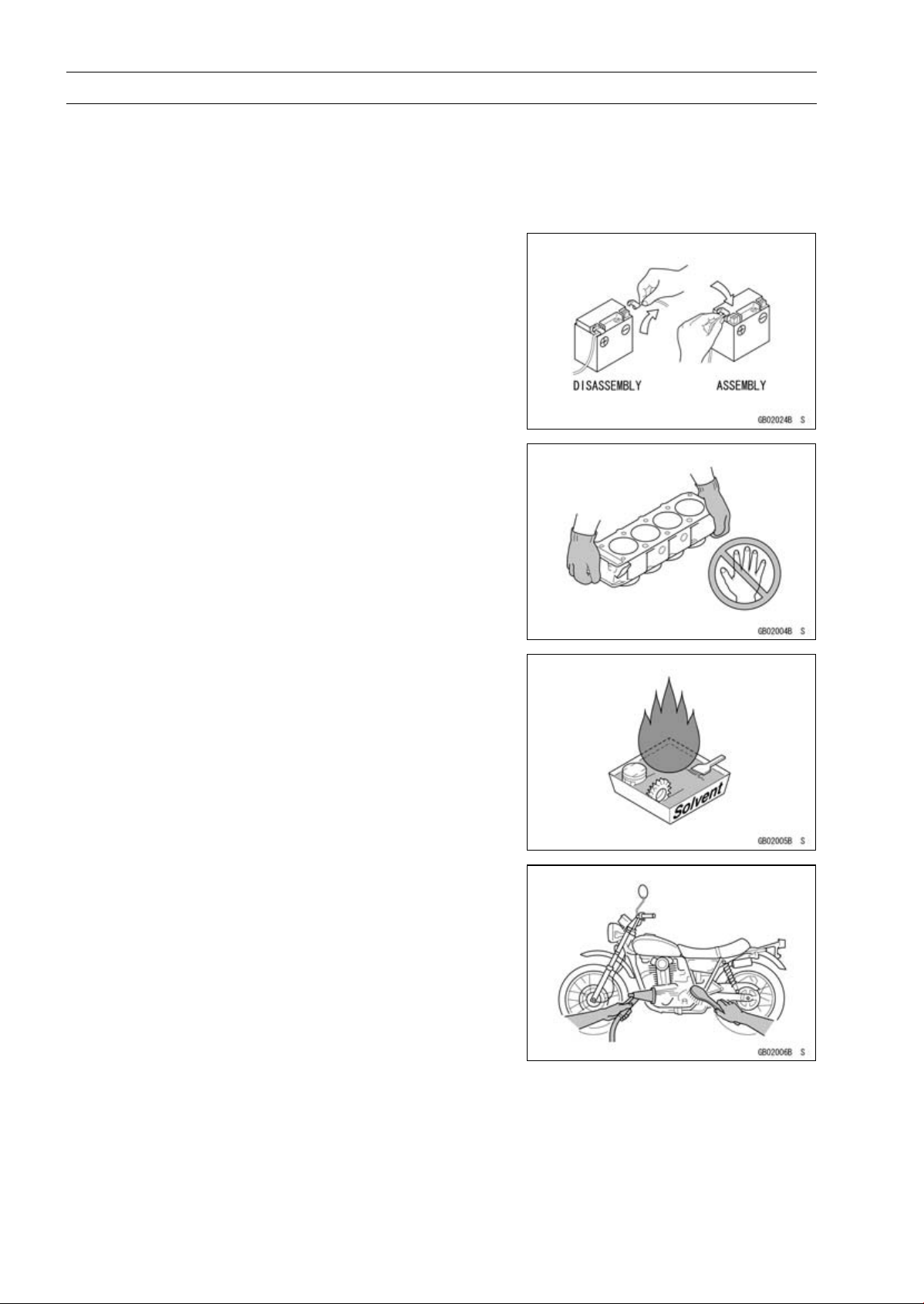
Battery Ground
Before completing any service on the motorcycle, discon-
nect the battery cables from the battery to prevent the en-
gine from accidentally turning over. Disconnect the ground
cable (–) first and then the positive (+). When completed
with the service, first connect the positive (+) cable to the
positive (+) terminal of the battery then the negative (–) ca-
ble to the negative terminal.
Edges of Parts
Lift large or heavy parts wearing gloves to prevent injury
from possible sharp edges on the parts.
Solvent
Use a high flash-point solvent when cleaning parts. High
flash-point solvent should be used according to directions
of the solvent manufacturer.
Cleaning Vehicle before Disassembly
Clean the vehicle thoroughly before disassembly. Dirt or
other foreign materials entering into sealed areas during ve-
hicle disassembly can cause excessive wear and decrease
performance of the vehicle.
GENERAL INFORMATION 1-3
Before Servicing
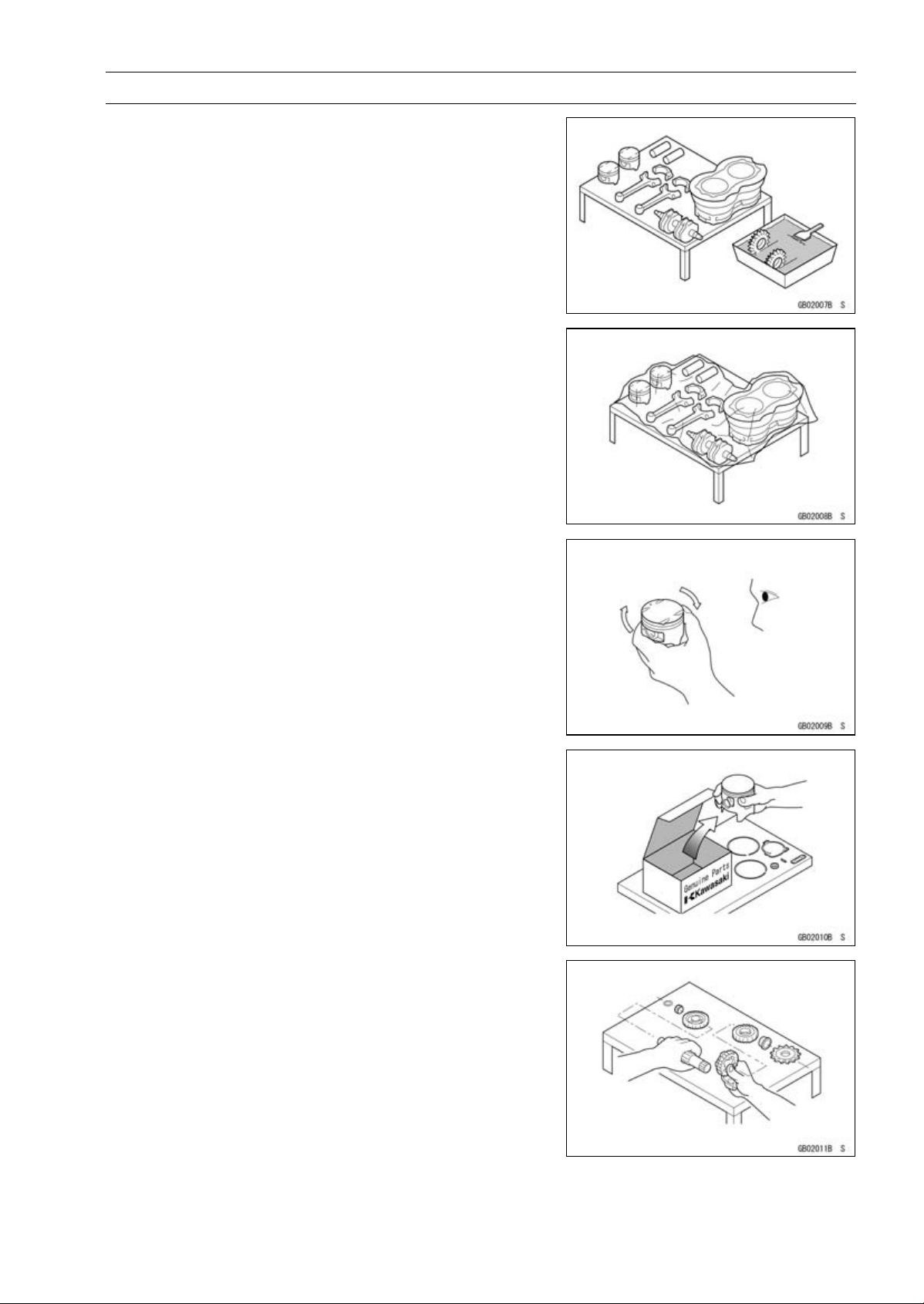
Arrangement and Cleaning of Removed Parts
Disassembled parts are easy to confuse. Arrange the
parts according to the order the parts were disassembled
and clean the parts in order prior to assembly.
Storage of Remov ed Parts
After all the parts including subassembly parts have been
cleaned, store the parts in a clean area. Put a clean cloth
or plastic sheet over the parts to protect from any foreign
materials that may collect before re-assembly.
Inspection
Reuse of worn or damaged parts may lead to serious ac-
cident. Visually inspect removed parts for corrosion, discol-
oration, or other damage. Refer to the appropriate sections
of this manual for service limits on individual parts. Replace
the parts if any damage has been found or if the part is be-
yond its service limit.
Replacement Parts
Replacement parts must be KAWASAKI genuine or
recommended by KAWASAKI. Gaskets, O-rings, oil seals,
grease seals, circlips, cotter pins or self-locking nuts must
be replaced with new ones whenever disassembled.
Assembly Order
In most cases assembly order is the reverse of disassem-
bly, however, if assembly order is provided in this Service
Manual, follow the procedures given.
1-4 GENERAL INFORMATION
Before Servicing
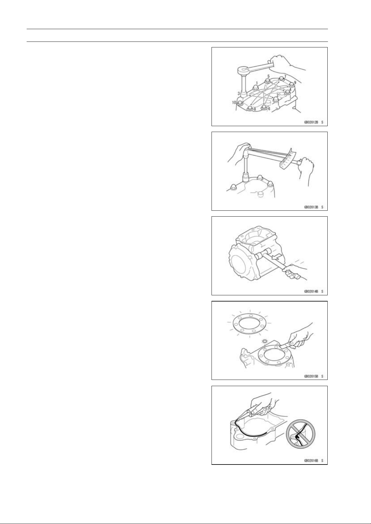
Tightening Sequence
Generally, when installing a part with several bolts, nuts,
or screws, start them all in their holes and tighten them to
a snug fit. Then tighten them according to the specified se-
quence to prevent case warpage or deformation which can
lead to malfunction. Conversely when loosening the bolts,
nuts, or screws, first loosen all of them by about a quar-
ter turn and then remove them. If the specified tightening
sequence is not indicated, tighten the fasteners alternating
diagonally.
Tightening Torque
Incorrect torque applied to a bolt, nut, or screw may
lead to serious damage. Tighten fasteners to the specified
torque using a good quality torque wrench.
All of the tightening torque values are for use with dry,
solvent - cleaned threads unless otherwise indicated. If a
fastener which should have dry, clean threads gets contami-
nated with lubricant, etc., applying even the specified torque
could damage it.
Force
Use common sense during disassembly and assembly,
excessive force can cause expensive or hard to repair dam-
age. When necessary, remove screws that have a non
-permanent locking agent applied using an impact driver.
Use a plastic-faced mallet whenever tapping is necessary.
Gasket, O-ring
Hardening, shrinkage, or damage of both gaskets and
O-rings after disassembly can reduce sealing performance.
Remove old gaskets and clean the sealing surfaces thor-
oughly so that no gasket material or other material remains.
Install the new gaskets and replace the used O-rings when
re-assembling.
Liquid Gasket, Non-permanent Locking Agent
For applications that require Liquid Gasket or a
Non-permanent Locking Agent, c lean the surfaces so
that no oil residue remains before applying liquid gasket or
non-permanent locking agent. Do not apply them exces-
sively. Excessive application can clog oil passages and
cause serious damage.
GENERAL INFORMATION 1-5
Before Servicing
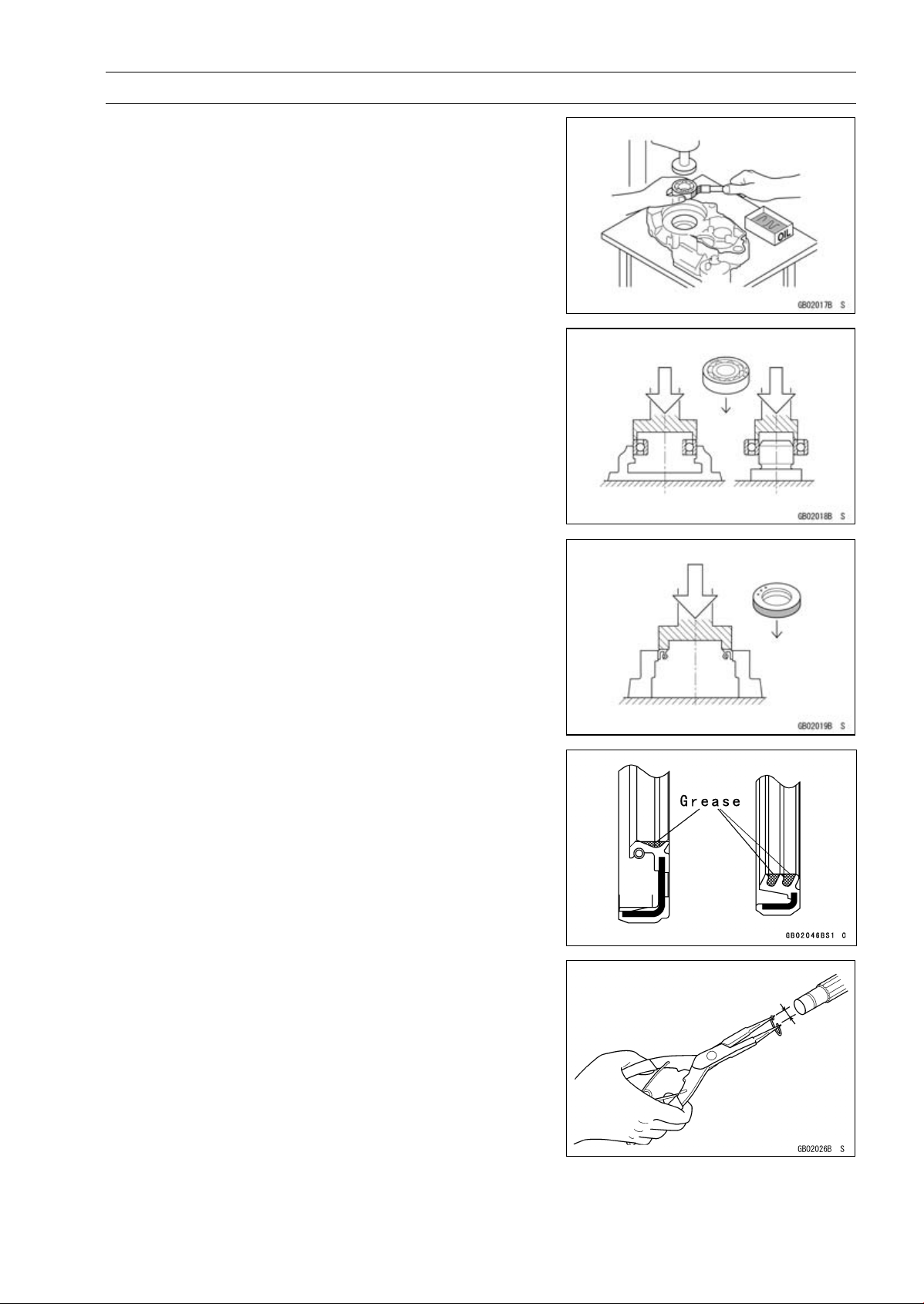
Press
For items such as bearings or oil seals that must be
pressed into place, apply small amount of oil to the con-
tact area. Be sure to maintain proper alignment and use
smooth movements when installing.
Ball Bearing and Needle Bearing
Do not remove pressed ball or needle unless removal is
absolutely necessary. Replace with new ones whenever
removed. Press bearings with the manufacturer and size
marks facing out. Press the bearing into place by putting
pressure on the correct bearing race as shown.
Pressing the incorrect race can cause pressure between
the i nner and outer race and result in bearing damage.
Oil Seal, Grease Seal
Do not remove pressed oil or grease seals unless removal
is necessary. Replace with new ones whenever removed.
Press new oil seals with manufacture and size marks facing
out. Make sure the seal is aligned properly when installing.
Apply specified grease to the lip of seal before installing
the seal.
Circlips, Cotter Pins
Replace the circlips or cotter pins that were removed with
new ones. Take care not to open the clip excessively when
installing to prevent deformation.
1-6 GENERAL INFORMATION
Before Servicing
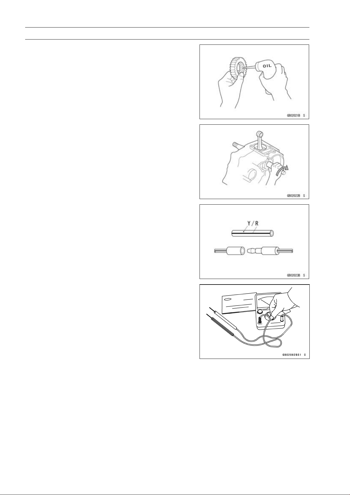
Lubrication
It is important to lubricate rotating or sliding parts during
assembly to minimize wear during initial operation. Lubri-
cation points are called out throughout this manual, apply
the specific oil or grease as specified.
Direction of Engine Rotation
When rotating the crankshaft by hand, the free play
amount of rotating direction will affect the adjustment. Ro-
tate the crankshaft to positive direction (clockwise viewed
from output side).
Electrical Wires
A two-color wire is identified first by the primary color and
then the stripe color. Unless instructed otherwise, electrical
wires must be connected to those of the same color.
Instrument
Use a meter that has enough accuracy for an accurate
measurement. Read the manufacture’s instructions thor-
oughly before using the meter. Incorrect values may lead
to improper adjustments.
GENERAL INFORMATION 1-7
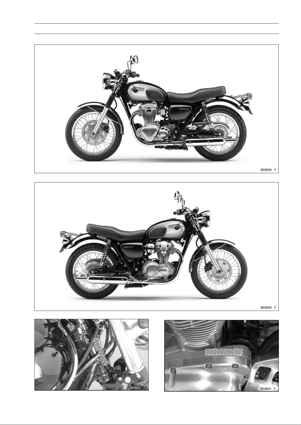
Model Identification
EJ800AB Left Side View
EJ800AB Right Side View
Frame Number Engine Number

1-8 GENERAL INFORMATION
General Specifications
Items EJ800AB ∼ AG
Dimensions
Overall Length 2 190 mm (86.22 in.)
Overall Width 790 mm (31.1 in.)
Overall Height 1 075 mm (42.32 in.)
Wheelbase
1 465 mm (57.68 in.)
Road Clearance 125 mm (4.92 in.)
Seat Height 790 mm (31.1 in.)
Curb Mass 217 kg (478 lb)
Front 100 kg (220 lb)
Rear 117kg(258lb)
Fuel Tank Capacity 14 L (3.7 US gal.)
Performance
Minimum Turning Radius 2.7 m (8.9 ft)
Engine
Type 4-stroke, SOHC, 2-cylinder
Cooling System Air-cooled
Bore and Stroke 77.0 × 83.0 mm (3.03 × 3.27 in.)
Displacement 773 cm³ (47.2 cu in.)
Compression Ratio 8.4 : 1
Maximum Horsepower
35 kW (48 PS) @6 500 r/min (rpm)
Maximum Torque
60 N·m (6.1 kgf·m, 44 ft·lb) @2 500 r/min (rpm)
Fuel System FI (Fuel Injection) KEIHIN TTK34 × 2
Fuel Type:
Minimum Octane Rating:
Research Octane Number (RON) 91
Starting System Electric start
er
Ignition System Battery and coil (transistorized)
Timing Advance
Electronically advanced (digital igniter)
Ignition Timing
0° BTDC @1 200
r/min (rpm)
Spark Plug NGK CR8E
Cylinder Numbering Method Left to right, 1-2
Firing Order 1-2
Valve Timing:
Intake:
Open 25° BTDC
Close 55° ABDC
Duration 260°
Exhaust:
Open 55° BBDC
Close 25° ATDC
Duration 260°
Lubrication System Forced lubrication (wet sump)
Engine Oil:
Type
API SG, SH, SJ, SL or SM with JASO MA, MA1 or MA2

GENERAL INFORMATION 1-9
General Specifications
Items EJ800AB ∼ AG
Viscosity SAE 10W-40
Capacity 3.2L(3.4USqt)
Drive Train
Primary Reduction System:
Type Gear
Reduction Ratio 2.095 (88/42)
Clutch Type Wet multi disc
Transmission:
Type 5-speed, constant mesh, return shift
Gear Ratios:
1st 2.353 (40/17)
2nd 1.591 (35/22)
3rd 1.240 (31/25)
4th
1.000 (28/28)
5th
0.852 (23/27)
Final Drive System:
Type Chain drive
Reduction Ratio 2.467 (37/15)
Overall Drive Ratio 4.403 at Top gear
Frame
Type Tubular, Double cradle
Caster (Rake Angle) 27°
Trail 108 mm (4.06 in.)
Front Tire:
Type TT100GP G
Size 100/90-19 M/C 57H
Rim Size J19 × 2.15
Rear Tire:
Type TT100GP
Size 130/80-18 M/C 66H
Rim Size J18M/C × MT2.75
Front Suspension:
Type Telescopic fork
Wheel Travel 130 mm (5.12 in.)
Rear Suspension:
Type Swingarm, shock absorber
Wheel Travel 106 mm (4.17 in.)
Brake Type:
Front Single disc
Rear Drum
Electrical Equipment
Battery 12 V 10 Ah (10 HR)
Headlight:
Type Semi-sealed beam

1-10 GENERAL INFORMATION
General Specifications
Items EJ800AB ∼ AG
Bulb 12 V 60/55 W (quartz-halogen)
Brake/Tail Light 12 V 21/5 W
Alternator:
Type
Three-phase AC
Maximum Output 14 V-18 A @7 000 r/min (r
pm)
Specifications are subject to change without notice, and may not apply to every country.
GENERAL INFORMATION 1-11
Unit Conversion Table
Prefixes for Units:
Prefix Symbol Power
mega M × 1 000 000
kilo k ×1000
centi c ×0.01
milli m × 0.001
micro µ × 0.000001
Units of Mass:
kg ×2.205=lb
g × 0.03527 = oz
Units of Volume:
L × 0.2642 = gal (US)
L × 0.2200 = gal (IMP)
L × 1.057 =
qt (US)
L × 0.8799 =
qt (IMP)
L × 2.113 = pint (US)
L × 1.816 = pint (IMP)
mL × 0.03381 = oz (US)
mL × 0.02816 = oz (IMP)
mL × 0.06102 = cu in.
Units of Force:
N × 0.1020 = kg
N × 0.2248 = lb
kg ×9.807=N
kg ×2.205=lb
Units of Length:
km × 0.6214 = mile
m × 3.281 = ft
mm × 0.03937 = in.
Units of Torque:
N·m × 0.1020 = kgf·m
N·m × 0.7376 = ft·lb
N·m × 8.851 = in·lb
kgf·m × 9.807 = N·m
kgf·m × 7.233 = ft·lb
kgf·m × 86.80 = in·lb
Units of Pressure:
kPa × 0.01020 = kgf/cm²
kPa × 0.1450 = psi
kPa × 0.7501 = cmHg
kgf/cm² × 98.07 = kPa
kgf/cm² × 14.22 = psi
cmHg×1.333=kPa
Units of Speed:
km/h
× 0.6214 = mph
Units of Power:
kW ×1.360=PS
kW ×1.341=HP
PS
× 0.7355 = kW
PS × 0.9863 = HP
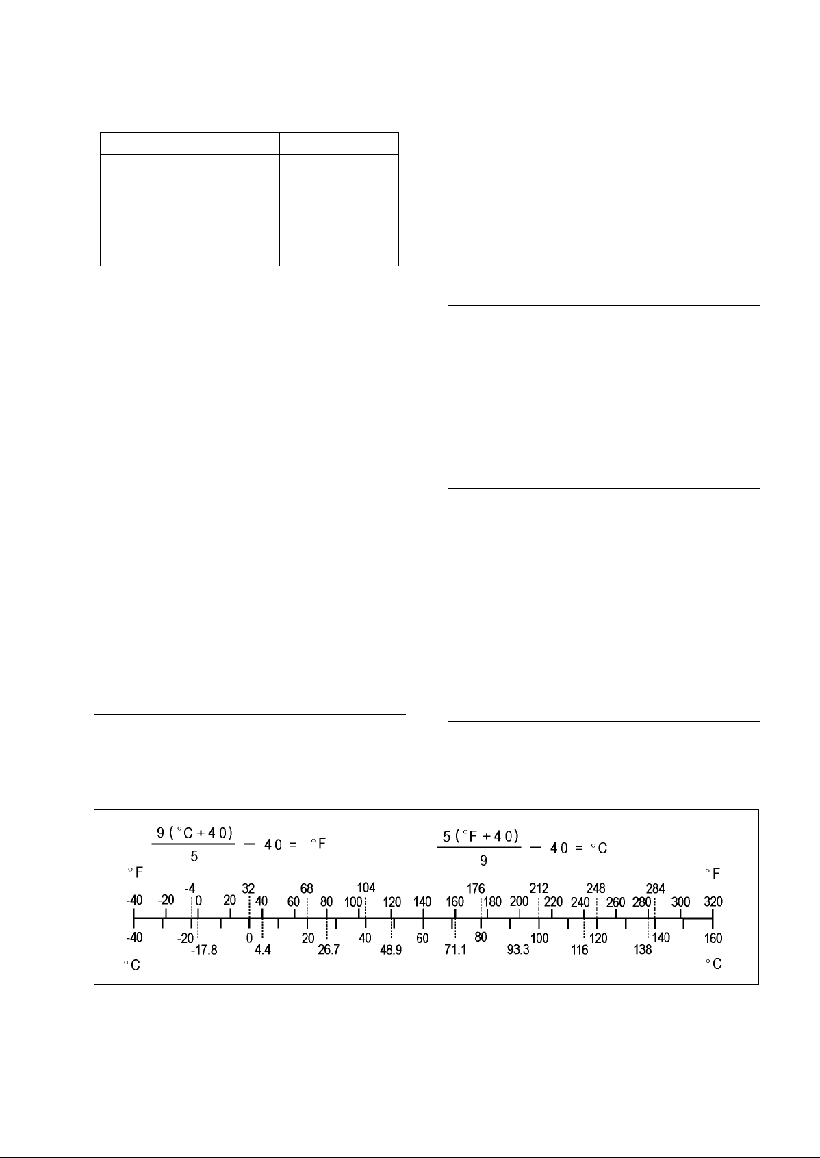
Units of Temperature:


PERIODIC MAINTENANCE 2-1
2
Periodic Maintenance
Table of Contents
Periodic Maintenance Chart .............. 2-2
Torque and Locking Agent................. 2-5
Specifications .................................... 2-10
Special Tools ..................................... 2-12
Periodic Maintenance Procedures..... 2-13
Fuel System.................................... 2-13
Air Cleaner Element Cleaning...... 2-13
Throttle Control System
Inspection.................................. 2-13
Engine Vacuum Synchronization
Inspection.................................. 2-14
Idle Speed Inspection .................. 2-17
Idle Speed Adjustment................. 2-17
Fuel Hose and Pipe Inspection
(fuel leak, damage, installation
condition)................................... 2-17
Engine Top End .............................. 2-18
Valve Clearance Inspection ......... 2-18
Valve Clearance Adjustment........ 2-19
Air Suction System Damage
Inspection.................................. 2-23
Clutch.............................................. 2-23
Clutch Operation Inspection......... 2-23
Wheels/Tires................................... 2-24
Tire Air Pressure Inspection......... 2-24
Wheel/Tire Damage Inspection.... 2-25
Tire Tread Wear Inspection.......... 2-25
Wheel Bearing Damage
Inspection.................................. 2-26
Spoke Tightness and Rim Runout
Inspection.................................. 2-26
Final Drive....................................... 2-28
Drive Chain Lubrication Condition
Inspection.................................. 2-28
Drive Chain Slack Inspection ....... 2-28
Drive Chain Slack Adjustment ..... 2-29
Wheel Alignment
Inspection/Adjustment............... 2-30
Drive Chain Wear Inspection ....... 2-31
Chain Guide Wear Inspection ...... 2-31
Brake System ................................. 2-32
Brake Fluid Leak Inspection......... 2-32
Brake Hose Damage and
Installation Condition
Inspection.................................. 2-32
Brake Fluid Level Inspection........ 2-32
Brake Pad Wear Inspection ......... 2-33
Brake Operation Inspection ......... 2-33
Brake Pedal Free Play Inspection 2-33
Brake Pedal Free Play
Adjustment ................................ 2-34
Brake Lining Wear Inspection ...... 2-34
Brake Light Switch Operation
Inspection .................................. 2-34
Suspensions ................................... 2-35
Front Forks/Rear Shock Absorber
Operation Inspection................. 2-35
Front Forks Oil Leak Inspection ... 2-36
Rear Shock Absorbers Oil Leak
Inspection .................................. 2-36
Swingarm Pivot Lubrication ......... 2-36
Steering System ............................. 2-36
Steering Play Inspection .............. 2-36
Steering Play Adjustment............. 2-37
Steering Stem Bearing
Lubrication................................. 2-37
Electrical System ............................ 2-38
Lights and Switches Operation
Inspection .................................. 2-38
Headlight Aiming Inspection ........ 2-40
Sidestand Switch Operation
Inspection .................................. 2-41
Engine Stop Switch Operation
Inspection .................................. 2-42
Others............................................. 2-42
Chassis Parts Lubrication ............ 2-42
Bolts, Nuts and Fasteners
Tightness Inspection ................. 2-44
Replacement Parts ......................... 2-45
Air Cleaner Element
Replacement............................. 2-45
Fuel Hose Replacement .............. 2-45
Engine Oil Change....................... 2-47
Oil Filter Replacement ................. 2-48
Brake Hose Replacement ............ 2-49
Brake Fluid Change ..................... 2-50
Master Cylinder Rubber Parts
Replacement............................. 2-51
Caliper Rubber Parts
Replacement............................. 2-52
Spark Plug Replacement ............. 2-53

2-2 PERIODIC MAINTENANCE
Periodic Maintenance Chart
The scheduled maintenance must be done in accordance with this chart to k eep the motorcycle in
good running condition.The initial maintenance is vitally important and must not be neglected.
Periodic Inspection
FREQUENCY Whichever
comes
first
* ODOME TER READING
× 1 000 km
(× 1 000 mile)
1 6 12 18 24 30 36
ITEM Every (0.6) (3.75) (7.5) (11.25) (15) (18.75) (22.5)
See
Page
Fuel System
Air cleaner element - clean
• • •
2-13
Throttle c ontrol system (play,
smooth return, no dra
g) - inspect
year
• • • •
2-13
Engine vacuum synchronization -
inspect
• • •
2-14
Idle speed - inspect
• • • •
2-17
Fuel leak (fuel hose and pipe) -
inspect
year
• • • •
2-17
Fuel hose and pipe damage -
inspect
year
• • • •
2-17
Fuel hose and pipe installation
condition - inspect
year
• • • •
2-17
Engine Top End
Valve clearance - inspect
• • •
2-18
Air suction system damage -
inspect
• • •
2-23
Clutch
Clutch operation (play,
disengagement, en
gagement)
-inspect
• • • •
2-23
Wheels and Tires
Tire air pressure - inspect year
• • •
2-24
Wheel/tire damage - inspect
• • •
2-25
Tire tread wear, abnormal wear -
inspect
• • •
2-25
Wheel bearing damage - inspect year
• • •
2-26
Spoke tightness and rim runout -
inspect
• • • • • • •
2-26
Final Drive
Drive chain lubrication condition -
inspect #
Every 600 km (375 mile) 2-28
Drive chain slack - inspect # Every 1 000 km (600 mile) 2-28
Drive chain wear - inspect #
• • • • • •
2-31
Chain guide wear - inspect
• • •
2-31
Brakes
Brake fluid leak - inspect year
• • • • • • •
2-32
Brake hose damage - inspect year
• • • • • • •
2-32

PERIODIC MAINTENANCE 2-3
Periodic Maintenance Chart
FREQUENCY Whichever
comes
first
* ODOMETER READING
× 1 000 km
(× 1 000 mile)
1 6 12 18 24 30 36
ITEM Every (0.6) (3.75) (7.5) (11.25) (15) (18.75) (22.5)
See
Page
Brake hose installation condition -
inspect
year
• • • • • • •
2-32
Brake fluid level - inspect
6
months
• • • • • • •
2-32
Brake pad wear - inspect #
• • • • • •
2-33
Brake operation (effectiveness,
play, no drag) - inspect
year
• • • • • • •
2-33
Brake lining wear - inspect
• • • • • •
2-34
Brake light switch operation -
inspect
• • • • • • •
2-34
Suspension
Front forks/rear shock absorbers
operation (damping and smooth
stroke) - inspect
• • •
2-35
Front forks/rear shock absorbers
oil leak - inspect
year
• • •
2-36
Swingarm pivot - lubricate
•
2-36
Steering
Steering play - inspect year
• • • •
2-37
Steering stem bearings - lubricate 2 years
•
2-37
Electrical System
Lights and switches operation -
inspect
year
• • •
2-38
Headlight aiming - inspect year
• • •
2-40
Sidestand switch operation -
inspect
year
• • •
2-41
Engine stop switch operation -
inspect
year
• • •
2-42
Others
Chassis parts - lubricate
year
• • •
2-42
Bolts and nuts tightness - inspect
• • • •
2-44
#: Service more frequently when operating in severe conditions; dusty, wet, muddy, high speed or
frequent starting/stopping.
*: For higher odometer readings, repeat at the frequency interval established here.
2-4 PERIODIC MAINTENANCE
Periodic Maintenance Chart
Periodic Replacement Parts
FREQUENCY Whichever
comes
first
* ODOMETER READING
× 1 000 km
(× 1 000 mile)
1 12 24 36 48
ITEM Every (0.6) (7.5) (15) (22.5) (30)
See
Page
Air cleaner element # - replace 2 years 2-45
Fuel hose - replace 5 years 2-45
Engine oil # - change year
• • • • •
2-47
Oilfilter-replace year
• • • • •
2-48
Brake hose - replace 4 years 2-49
Brake fluid - change 2 years
• •
2-50
Rubber parts of master cylinder and caliper -
replace
4 years
•
2-51,
2-52
Spark plug - replace
• • • •
2-53
#: Service more frequently when operating in severe conditions; dusty, wet, muddy, high speed or
frequent starting/stopping.
*: For higher odometer readings, repeat at the frequency interval established here.

PERIODIC MAINTENANCE 2-5
Torque and L ocking Agent
The following tables list the tightening torque for the major fasteners requiring use of a
non-permanent locking agent or silicone sealant etc.
All of the values are for use with dry solvent - cleaned threads unless otherwise indicated.
Letters used in the “Remarks” column mean:
CP: Bolt with copper-plated washer.
G: Apply grease.
HL: Apply high-lock agent to the threads.
L: Apply a non-permanent locking agent.
Lh: Left-hand Threads
M: Apply molybdenum disulfide grease.
MO: Apply molybdenum disulfide oil solution.
(mixture of the engine oil and molybdenum disulfide grease in a weight ratio 10 : 1)
R: Replacement parts
S: Follow the specified tightening sequence.
Si: Apply silicone grease.
SS: Apply silicone sealant.
Torque
Fastener
N·m kgf·m ft·lb
Remarks
Fuel System
Fuel Reserve Switch Screws
2.1 0.21 19 in·lb
Fuel Pump Bolts 9.8 1.0 87 in·lb L
Throttle Cable Plate Bolt 5.9 0.60 52 in·lb
Delivery Pipe Mounting Screws 3.43 0.35 30 in·lb
Engine Temperature Sensor 9.8 1.0 87 in·lb
Oxygen Sensor 25 2.5 18
Crankshaft Sensor Bolts
7.8 0.80 69 in·lb L
Speed Sensor Mounting Bolt
4.5 0.46 40 in·lb
Vehicle-down S
ensor Mounting Bolts
4.0 0.40 35 in·lb
Engine Top End
Spark Plug Hole Holder Cover Bolts 7.8 0.8 69 in·lb
Cylinder Head Cover Bolts 9.8 1.0 87 in·lb
Bevel Gear Cover Bolts
3.9 0.4 35 in·lb L
Air Suction Valve Cover Bolts
12 1.2 106 in·lb L
Cylinder Head
Bolts (New Bolts)
49 5.0 36
MO, S
Cylinder Head Bolts (Used Bolts) 47 4.8 35 MO, S
Spark Plugs 13 1.3 115 in·l b
Spark Plug Hole Pipes 120 12.2 89 L
Camshaft Cap Bolts (8 mm) 25 2.5 18 S
Camshaft Cap Bolts (6 mm) 12 1.2 106 in·lb S
Oil Fitting Bracket Bolts 12 1.2 106 in·lb L
Oxygen Sensor 25 2.5 18
Muffler Bracket Bolts 21 2.1 15
Rocker Shaft Bolts 12 1.2 106 in·lb L
Camshaft Locating Plate Bolts
12 1.2 106 in·lb
Driven Bevel Gear Bolts
20 2.0 15 L
Bevel Gea
r Mounting Nuts
59 6.0 44 R
Gear Case 98 10 72 L

2-6 PERIODIC MAINTENANCE
Torque and Locking Agent
Torque
Fastener
N·m kgf·m ft·lb
Remarks
Bevel Gear Case Locknuts 20 2.0 15
Bevel Gear Case Bolts
12 1.2 106 in·lb
Bevel Gear Oil Passage Nozzle
3.5 0.36 31 in·lb
Bevel Gear Holder Scre
ws
4.9 0.5 43 in·lb L
Bearing Holder Allen Bolts 7.8 0.8 69 in·lb L
Locknut Stop Screw 2.1 0.2 1.5 L
Clutch
Clutch Lever Holder Bolts
7.8 0.80 69 in·lb
S
Clutch Hub Nut
145 14.8 107 R
Clutch Spring Bolts
9.8 1.0 87 in·lb
Clutch Cover Damper Plate Bolts 12 1.2 106 in·lb L
Clutch Cable Lower Holder Bolts 12 1.2 106 in·lb L
Clutch Release Case Mounting Bolt (L = 80 mm) 12 1.2 106 in·lb
Clutch Release Case Mounting Bolt (L = 70 mm) 12 1.2 106 in·lb
Release Shaft Locating Bolt 9.8 1.0 87 in·lb
Release Lever Clamp Bolt 12 1.2 106 in·lb
Clutch Cover Bolts (M6, L = 25) 12 1.2 106 in·lb
Clutch Cover Bolts (M6, L = 50) 12 1.2 106 in·lb
Clutch Cover Bolt (M6, L = 70) 12 1.2 106 in·lb L
Engine Lubrication System
Oil Fitting Bracket Bolts (L = 20 mm)
12 1.2 106 in·lb L
Oil Fitting Br
acket Bolt (L = 25 mm)
12 1.2 106 in·lb L
Oil Filler Cap 1.5 0.15 13 in·lb (Hand tighten)
Oil Filter Cap Bolts 12 1.2 106 in·lb L
Oil Filter 17 1.7 13
Oil Filter Passage Pipe 25 2.5 18 SS
Oil Pressure Relief Nozzle 3.4 0.35 30 in·lb
Oil Passage Nozzle 3.4 0.35 30 in·lb
Oil Pressure Switch Plug 20 2.0 15 L
Oil Pressure Switch 15 1.5 11 SS
Oil Pump Cover Bolts 9.8 1.0 87 in·lb L
Oil Pump Gear Bolt
12 1.2 106 in·lb L
Oil Pipe Plate Bolt
9.8 1.0 87 in·lb L
Oil Pressu
re Relief Valve
15 1.5 11 HL
Oil Drain Plug 29 3.0 21
Oil Pan Bolts 12 1.2 106 in·lb L(2)
Engine Removal/Installation
Engine Bracket Bolts (L = 60 mm) 34 3.5 25
Engine Bracket Bolts (L = 16 mm) 25 2.5 18
Engine Mo
unting Nuts
44 4.5 32 R
Lower Engine Mounting Nut 59 6.0 44 R

PERIODIC MAINTENANCE 2-7
Torque and L ocking Agent
Torque
Fastener
N·m kgf·m ft·lb
Remarks
Crankshaft/Transmission
Connecting Rod Big End Cap Nuts
see the
text
← ← MO
Breather Cap Bolts 12 1.2 106 in·lb
Starter Motor Clutch Bolts
34 3.5 25 L
Breather Plate Screws
4.9 0.50 43 in·lb L
External Shift Mecha
nism Cover Bolts (M6, L =
35 mm)
12 1.2 106 in·lb
Neutral Switch Screws 3.9 0.40 35 in·lb L
External Shift Mechanism Cover Bolts (M6, L =
25 mm)
12 1.2 106 in·lb L
Return Spring Pin
42 4.3 31 L
Rear Engine Cover B
olts (M6, L = 30 mm)
12 1.2 106 in·lb
Rear Engine Cover Bolts (M6, L = 22 mm) 12 1.2 106 in·lb
Upper Crankcase Bolts (M8, L = 73 mm) 29 3.0 21 CP (1)
Upper Crankcase Bolt (M6, L = 45 mm) 20 2.0 15
Upper Crankcase Bolt (M6, L = 70 mm) 20 2.0 15
Upper Crankcase Bolts (M6, L = 117 mm) 20 2.0 15
Upper Crankcase Bolts (M8, L = 50 mm) 29 3.0 21
Lower Crankcase Bolts (M9, L = 130 mm) 41 4.2 30 S, MO
Lower Crankcase Bolts (M9, L = 110 mm) 41 4.2 30 S, MO
Lower Crankcase Bolt (M9, L = 90 mm) 41 4.2 30 S, MO
Lower Crankcase Bolts (M6, L = 45 mm)
20 2.0 15
S
Lower Crankcase Bolts (M8, L = 73 mm)
29 3.0 21
S, MO, CP (1)
Lower Crankca
se Bolt (M6, L = 32 mm)
20 2.0 15
S
Lower Crankcase Bolt (M8, L = 60 mm) 29 3.0 21 S, MO
Shift Drum Cam Bolt 12 1.2 106 in·lb L
Shift Drum Bearing H older Screw 4.9 0.50 43 in·lb S, L
Shift Drum Bearing Holder Bolt 12 1.2 106 in·lb S, L
Gear Positioning Lever Bolt 12 1.2 106 in·lb L
Wheels/Tires
Spoke Nipples 5.2 0.53 46 in·lb
Front Axle Clamp Bolt 20 2.0 15
Front Axle Nut 98 10 72
Rear Axle Nut 98 10 72
Final Drive
Engine Sprocket Cover Bolts 12 1.2 106 in·lb L
Engine Sprocket Nut 147 15 108 MO
Rear Sprocket Nuts 59 6.0 44 R
Brakes
Brake Reservoir Cap Screws 1.5 0.15 13 in·lb
Brake Lever Pivot Bolt 1.0 0.10 9in·lb Si
Brake Leve
r Pivot Bolt Locknut
5.9 0.60 52 in·lb
Master Cylinder Clamp Bolts 11 1.1 97 in·lb S

2-8 PERIODIC MAINTENANCE
Torque and Locking Agent
Torque
Fastener
N·m kgf·m ft·lb
Remarks
Front Brake Light Switch Screw 1.2 0.12 11 i n · lb
Brake Hose Banjo Bolts 25 2.5 18
Brake Disc Mounting Bolts 23 2.3 17
Caliper Mounting Bolts
34 3.5 25
Bleed Valve 7.8 0.80 69 in·lb
Brake Pedal Bolt (EJ800AB) 25 2.5 18
Brake Pedal Bolt (EJ800AC ∼) 34 3.5 25
Torque Link Bolt 34 3.5 25
Torque Link Nut 34 3.5 25
Cam Lever Bolt
19 1.9 14
Suspension
Front Fork Top Plugs 23 2.3 17
Front Fork Clamp Bolts (Upper) 20 2.0 15
Front Axle Clamp Bolt
20 2.0 15
Front Fork Bottom Allen Bolts 30 3.1 22 L
Front Fork Clamp Bolts (Lower) 29 3.0 21
Rear Shock Absorber Nuts 59 6.0 44
Rear Shock Absorber Bolts 44 4.5 32
Swingarm Pivot Shaft Nut 98 10 72
Torque Link Bolt 34 3.5 25
Torque Link Nut 34 3.5 25
Steering
Handlebar Clamp Bolts 25 2.5 18 S
Steering Stem Head Nut 49 5.0 36
Front Fork Clamp Bolts (Upper) 20 2.0 15
Steering Stem Nut 4.9 0.50 43 in·lb
Front Fork Clamp Bolts (Lower) 29 3.0 21
Frame
Rear View Mirror Locknut (Upper) 30 3.1 22 G, Lh
Rear View Mirror Nut (Lower) 30 3.1 22
Sidestand Switch Bolt 8.8 0.9 78 in·lb L
Sidestand Bolt 44 4.5 32
Sidestand Nut 44 4.5 32 R
Front Step Mounting Bolts 59 6.0 44
Center Stand Bolt 44 4.5 32
Grab Rail Bolts 25 2.5 18
Electrical System
Tail/Brake Light Mounting Nuts
5.9 0.60 52 in·lb
Starter Motor Terminal Locknut
11 1.1 97 in·lb
Starter Motor
Mounting Bolts
9.8 1.0 87 in·lb L
Starter Motor Through Bolts 4.9 0.50 43 in·lb
Starter Motor Cable Terminal Nut 4.9 0.50 43 in·lb
One-Way Clutch Mounting Allen Bolts 34 3.5 25 L

PERIODIC MAINTENANCE 2-9
Torque and L ocking Agent
Torque
Fastener
N·m kgf·m ft·lb
Remarks
Stator Coil Bolts 12 1.2 106 in·lb L
Alternator Rotor Bolt 155 15.8 114
MO
Alternator Lead Holding Plate Bolts 7.8 0.80 69 in·lb L
Crankshaft Sensor Bracket Bolt (L = 45 mm) 12 1.2 106 in·lb L
Crankshaft Sensor Bracket Bolts (L = 40 mm) 12 1.2 106 in·lb L
Crankshaft Sensor Bolts 7.8 0.80 69 in·lb L
Crankshaft Sensor Lead Guard Plate Bolts 10 1.0 89 in·lb L
Oil Pressure Switch
15 1.5 11
SS
Speed Sensor Mounting Bolt
4.5 0.46 40 in·lb L
Neutral Switch Scre
ws
3.9 0.40 35 in·lb L
Alternator Cover Bolts (M6, L = 35 mm) 12 1.2 106 in·lb (L, 2)
Alternator Cover Bolts (M6, L = 40 mm) 12 1.2 106 in·lb
Alternator Cover Bolts (M6, L = 45 mm) 12 1.2 106 in·lb
Front Brake Light Switch Screw 1.2 0.12 11 in·lb
Spark Plugs 13 1.3 115 in·l b
Sidestand Switch Bolt 8.8 0.9 78 in·lb L
Fuel Reserve Switch Screws 2.1 0.21 19 in·lb
Oxygen Sensor 25 2.5 18
The table below, relating tightening torque to thread diameter, lists the basic torque for the bolts and
nuts. Use this table for only the bolts and nuts which do not require a specific torque value. All of the
values are for use with dry solvent-cleaned threads.
Basic Torque for General Fasteners
Torque
Threads Diameter
(mm)
N·m
kgf
·m
ft·
lb
5 3.4 ∼ 4.9 0.35 ∼ 0.50 30 ∼ 43 in·lb
6 5.9 ∼ 7.8 0.60 ∼ 0.80 52 ∼ 69 in·lb
8 14 ∼ 19 1.4 ∼ 1.9 10.0 ∼ 13.5
10 25 ∼ 34 2.6 ∼ 3.5 19.0 ∼ 25
12 44 ∼ 61 4.5 ∼ 6.2 33 ∼ 45
14 73 ∼ 98 7.4 ∼ 10.0 54 ∼ 72
16 115 ∼ 155 11.5 ∼ 16.0 83 ∼ 115
18 165 ∼ 225 17.0 ∼ 23.0 125 ∼ 165
20 225 ∼ 325 23.0 ∼ 33.0 165 ∼ 240

2-10 PERIODIC MAINTENANCE
Specifications
Item Standard Service Limit
Fuel System (DFI)
Throttle Grip Free Play 2 ∼ 3 mm (0.08 ∼ 0.12 in.)
–––
Idle Speed 1200±50r/min(rpm)
–––
Throttle Body Vacuum 21.3 ∼ 26.7 kPa (160 ∼ 200 mmHg) at idle
speed (for reference)
–––
Engine Synchronization
Vacuum
Less than 2.4 kPa (18 mmHg) difference
between both cylinders
–––
Air Cleaner Element
Polyurethane Foam –––
Engine Top End
Valve Clearance:
Exhaust
0.14 ∼ 0.19 mm (0.0055 ∼ 0.0075 in.)
–––
Intake
0.08 ∼ 0.13 mm (0.0031 ∼ 0.0051 in.)
–––
Clutch
Clutch Lever Free Play 2 ∼ 3 mm (0.08 ∼ 0.12 in.) –––
Engine Lubrication System
Engine Oil:
Type
API SG, SH, SJ, SL or SM with JASO MA,
MA1 or MA2
–––
Viscosity
SAE 10W-40
–––
Capacity 2.7 L (2.9 US qt) (when filter is not removed)
–––
2.9 L (3.1 US qt) (when filter is removed)
–––
3.2 L (3.4 US qt) (when engine is completely
dry)
–––
Level
Between upper and lower level lines (Wait
2 ∼ 3 minutes after idling or running)
–––
Wheels/Tires
Tread Depth:
Front
4.4 mm (0.17 in.) 1 mm (0.04 in.)
Rear
7.4 mm (0.29 in.) 2 mm (0.08 in.) up to
130km/h (80 mph)
3 mm (0.12 in.) over
130km/h (80 mph)
Air Pressure (When Cold):
Front
200 kPa (2.0 kgf/cm², 2 8 psi)
–––
Rear
Up to 97.5 kg (215 lb) load:
225 kPa (2.25 kgf/cm², 32 psi)
–––
Over 97.5 kg (215 lb) load:
250 kPa (2.50 kgf/cm², 36 psi)
–––
Rim Runout:
Front:
Axial
TIR 0.7 mm (0.03 i n.) or less TIR 2.0 mm (0.08 in.)
Radial
TIR 1 mm (0.04 in.) or less TIR 2.0 mm (0.08 in.)
Rear:
Axial
TIR 0.8 mm (0.03 i n.) or less TIR 2.0 mm (0.08 in.)
Radial
TIR 1.2 mm (0.05 i n.) or less TIR 2.0 mm (0.08 in.)
Loading...