


 Loading...
Ninja ZX-10R
Ninja ZX-10R ABS
Motorcycle
Service Manual

Quick Reference Guide
This quick reference guide will assist you in locating a desired topic or procedure.
•Bend the pages back to match the black tab of the desired chapter number with the black tab on the edge at each table of contents page.
•Refer to the sectional table of contents for the exact pages to locate the specific topic required.
General Information |
1 |
j |
|
|
|
Periodic Maintenance |
2 |
j |
|
|
|
Fuel System (DFI) |
3 |
j |
|
|
|
Cooling System |
4 |
j |
|
|
|
Engine Top End |
5 |
j |
|
|
|
Clutch |
6 |
j |
|
|
|
Engine Lubrication System |
7 |
j |
|
|
|
Engine Removal/Installation |
8 |
j |
|
|
|
Crankshaft/Transmission |
9 |
j |
|
|
|
Wheels/Tires |
10 |
j |
|
|
|
Final Drive |
11 |
j |
|
|
|
Brakes |
12 |
j |
|
|
|
Suspension |
13 |
j |
|
|
|
Steering |
14 |
j |
|
|
|
Frame |
15 |
j |
|
|
|
Electrical System |
16 |
j |
|
|
|
Self-Diagnosis System |
17 |
j |
|
|
|
Appendix |
18 |
j |

Ninja ZX-10R
Ninja ZX-10R ABS
Motorcycle
Service Manual
All rights reserved. No parts of this publication may be reproduced, stored in a retrieval system, or transmitted in any form or by any means, electronic mechanical photocopying, recording or otherwise, without the prior written permission of Quality Assurance Division/Motorcycle & Engine Company/Kawasaki Heavy Industries, Ltd., Japan.
No liability can be accepted for any inaccuracies or omissions in this publication, although every possible care has been taken to make it as complete and accurate as possible.
The right is reserved to make changes at any time without prior notice and without incurring an obligation to make such changes to products manufactured previously. See your Motorcycle dealer for the latest information on product improvements incorporated after this publication.
All information contained in this publication is based on the latest product information available at the time of publication. Illustrations and photographs in this publication are intended for reference use only and may not depict actual model component parts.
© 2010 Kawasaki Heavy Industries, Ltd. |
4th Edition (0) : Aug. 7, 2012 |

LIST OF ABBREVIATIONS
A |
ampere(s) |
lb |
pound(s) |
ABDC |
after bottom dead center |
m |
meter(s) |
AC |
alternating current |
min |
minute(s) |
ATDC |
after top dead center |
N |
newton(s) |
BBDC |
before bottom dead center |
Pa |
pascal(s) |
BDC |
bottom dead center |
PS |
horsepower |
BTDC |
before top dead center |
psi |
pound(s) per square inch |
°C |
degree(s) Celsius |
r |
revolution |
DC |
direct current |
rpm |
revolution(s) per minute |
F |
farad(s) |
TDC |
top dead center |
°F |
degree(s) Fahrenheit |
TIR |
total indicator reading |
ft |
foot, feet |
V |
volt(s) |
g |
gram(s) |
W |
watt(s) |
h |
hour(s) |
Ω |
ohm(s) |
L |
liter(s) |
|
|
COUNTRY AND AREA CODES
AT |
Austria |
|
AU |
Australia |
|
BR |
Brazil |
|
CA |
Canada |
|
CAL |
California |
|
CH |
Switzerland |
|
DE |
Germany |
|
EUR |
Europe |
|
|
|
GB
PH SEA-B1
SEA-B2 US
WVTA (FULL H)
GB WVTA (FULL H)
WVTA (78.2 H)
United Kingdom Philippines
Southeast Asia B1 (with Evaporative Emission Control System)
Southeast Asia B2 United States
WVTA Model with Honeycomb Catalytic Converter (Full Power)
WVTA Model with Honeycomb Catalytic Converter (Left Side Traffic Full Power)
WVTA Model with Honeycomb Catalytic Converter (Restricted Power)

EMISSION CONTROL INFORMATION
To protect the environment in which we all live, Kawasaki has incorporated crankcase emission (1) and exhaust emission (2) control systems in compliance with applicable regulations of the United States Environmental Protection Agency and California Air Resources Board. Additionally, Kawasaki has incorporated an evaporative emission control system (3) in compliance with applicable regulations of the California Air Resources Board on vehicles sold in California only.
1. Crankcase Emission Control System
This system eliminates the release of crankcase vapors into the atmosphere. Instead, the vapors are routed through an oil separator to the intake side of the engine. While the engine is operating, the vapors are drawn into combustion chamber, where they are burned along with the fuel and air supplied by the fuel injection system.
2. Exhaust Emission Control System
This system reduces the amount of pollutants discharged into the atmosphere by the exhaust of this motorcycle. The fuel, ignition, and exhaust systems of this motorcycle have been carefully designed and constructed to ensure an efficient engine with low exhaust pollutant levels.
The exhaust system of this model motorcycle manufactured primarily for sale in California includes a catalytic converter system.
3. Evaporative Emission Control System
Vapors caused by fuel evaporation in the fuel system are not vented into the atmosphere. Instead, fuel vapors are routed into the running engine to be burned, or stored in a canister when the engine is stopped. Liquid fuel is caught by a vapor separator and returned to the fuel tank.
The Clean Air Act, which is the Federal law covering motor vehicle pollution, contains what is commonly referred to as the Act’s “tampering provisions”.
“Sec. 203(a) The following acts and the causing thereof are prohibited...
(3)(A) for any person to remove or render inoperative any device or element of design installed on or in a motor vehicle or motor vehicle engine in compliance with regulations under this title prior to its sale and delivery to the ultimate purchaser, or for any manufacturer or dealer knowingly to remove or render inoperative any such device or element of design after such sale and delivery to the ultimate purchaser.
(3)(B) for any person engaged in the business of repairing, servicing, selling, leasing, or trading motor vehicles or motor vehicle engines, or who operates a fleet of motor vehicles knowingly to remove or render inoperative any device or element of design installed on or in a motor vehicle or motor vehicle engine in compliance with regulations under this title following its sale and delivery to the ultimate purchaser...”
NOTE
○The phrase “remove or render inoperative any device or element of design” has been generally interpreted as follows.
1.Tampering does not include the temporary removal or rendering inoperative of devices or elements of design in order to perform maintenance.
2.Tampering could include.
a.Maladjustment of vehicle components such that the emission standards are exceeded.
b.Use of replacement parts or accessories which adversely affect the performance or durability of the motorcycle.
c.Addition of components or accessories that result in the vehicle exceeding the standards.
d.Permanently removing, disconnecting, or rendering inoperative any component or element of design of the emission control systems.
WE RECOMMEND THAT ALL DEALERS OBSERVE THESE PROVISIONS OF FEDERAL LAW, THE VIOLATION OF WHICH IS PUNISHABLE BY CIVIL PENALTIES NOT EXCEEDING $10 000 PER VIOLATION.

TAMPERING WITH NOISE CONTROL SYSTEM PROHIBITED
Federal law prohibits the following acts or the causing thereof. (1) The removal or rendering inoperative by any person other than for purposes of maintenance, repair, or replacement, of any device or element of design incorporated into any new vehicle for the purpose of noise control prior to its sale or delivery to the ultimate purchaser or while it is in use, or (2) the use of the vehicle after such device or element of design has been removed or rendered inoperative by any person.
Among those acts presumed to constitute tampering are the acts listed below.
•Replacement of the original exhaust system or muffler with a component not in compliance with Federal regulations.
•Removal of the muffler(s) or any internal portion of the muffler(s).
•Removal of the air box or air box cover.
•Modifications to the muffler(s) or air intake system by cutting, drilling, or other means if such modifications result in increased noise levels.

Foreword
This manual is designed primarily for use by trained mechanics in a properly equipped shop. However, it contains enough detail and basic information to make it useful to the owner who desires to perform his own basic maintenance and repair work. A basic knowledge of mechanics, the proper use of tools, and workshop procedures must be understood in order to carry out maintenance and repair satisfactorily. Whenever the owner has insufficient experience or doubts his ability to do the work, all adjustments, maintenance, and repair should be carried out only by qualified mechanics.
In order to perform the work efficiently and to avoid costly mistakes, read the text, thoroughly familiarize yourself with the procedures before starting work, and then do the work carefully in a clean area. Whenever special tools or equipment are specified, do not use makeshift tools or equipment. Precision measurements can only be made if the proper instruments are used, and the use of substitute tools may adversely affect safe operation.
For the duration of the warranty period, we recommend that all repairs and scheduled maintenance be performed in accordance with this service manual. Any owner maintenance or repair procedure not performed in accordance with this manual may void the warranty.
To get the longest life out of your vehicle.
•Follow the Periodic Maintenance Chart in the Service Manual.
•Be alert for problems and non-scheduled maintenance.
•Use proper tools and genuine Kawasaki Motorcycle parts. Special tools, gauges, and testers that are necessary when servicing Kawasaki motorcycles are introduced by the Service Manual. Genuine parts provided as spare parts are listed in the Parts Catalog.
•Follow the procedures in this manual carefully. Don’t take shortcuts.
•Remember to keep complete records of maintenance and repair with dates and any new parts installed.
How to Use This Manual
In this manual, the product is divided into its major systems and these systems make up the manual’s chapters. The Quick Reference
Guide shows you all of the product’s system and assists in locating their chapters. Each chapter in turn has its own comprehensive Table of Contents.
For example, if you want ignition coil information, use the Quick Reference Guide to locate the Electrical System chapter. Then, use the Table of Contents on the first page of the chapter to find the Ignition Coil section.
Whenever you see symbols, heed their instructions! Always follow safe operating and maintenance practices.

 DANGER
DANGER indicates a hazardous situation which, if not avoided, will result in death or serious injury.
 WARNING
WARNING indicates a hazardous situation which, if not avoided, could result in death or serious injury.
NOTICE
NOTICE is used to address practices not related to personal injury.
This manual contains four more symbols which will help you distinguish different types of information.
NOTE
○This note symbol indicates points of particular interest for more efficient and convenient operation.
•Indicatesdone. a procedural step or work to be ○Indicates a procedural sub-step or how to do the work of the procedural step it follows. It
also precedes the text of a NOTE.
 Indicates a conditional step or what action to take based on the results of the test or inspection in the procedural step or sub-step it follows.
In most chapters an exploded view illustration of the system components follows the Table of Contents. In these illustrations you will find the instructions indicating which parts require specified tightening torque, oil, grease or a locking agent during assembly.
GENERAL INFORMATION 1-1
General Information |
|
|
|
Table of Contents |
|
|
|
|
1 |
|
|
Before Servicing |
1-2 |
|
|
|
|
||
Model Identification................................................................................................................. |
1-7 |
|
|
General Specifications............................................................................................................ |
1-11 |
|
|
Technical Information-Sport-Kawasaki TRaction Control System (S-KTRC) ......................... |
1-14 |
|
|
Technical Information-Power Mode ........................................................................................ |
1-17 |
|
|
Technical Information-Kawasaki Intelligent anti-lock Brake System (KIBS/ZX1000K model |
|
|
|
only)..................................................................................................................................... |
1-19 |
|
|
Technical Information - Electronic Steering Damper (ESD/ZX1000JD/KD models) .............. |
1-23 |
|
|
Unit Conversion Table ............................................................................................................ |
1-26 |
|
|
1-2 GENERAL INFORMATION
Before Servicing
Before starting to perform an inspection service or carry out a disassembly and reassembly operation on a motorcycle, read the precautions given below. To facilitate actual operations, notes, illustrations, photographs, cautions, and detailed descriptions have been included in each chapter wherever necessary. This section explains the items that require particular attention during the removal and reinstallation or disassembly and reassembly of general parts.
Especially note the following.
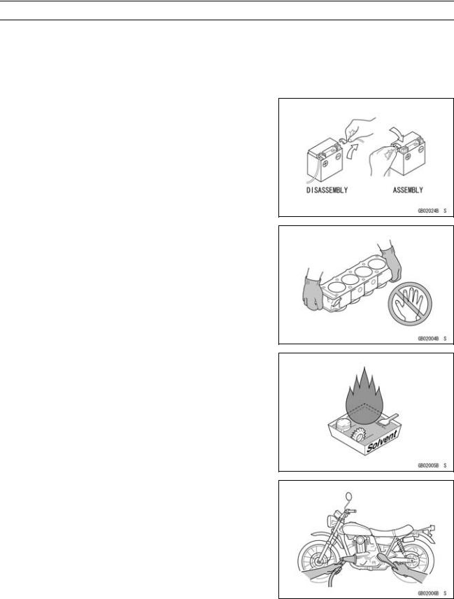
Battery Ground
Before completing any service on the motorcycle, disconnect the battery cables from the battery to prevent the engine from accidentally turning over. Disconnect the ground cable (–) first and then the positive (+). When completed with the service, first connect the positive (+) cable to the positive (+) terminal of the battery then the negative (–) cable to the negative terminal.
Edges of Parts
Lift large or heavy parts wearing gloves to prevent injury from possible sharp edges on the parts.
Solvent
Use a high flash-point solvent when cleaning parts. High flash-point solvent should be used according to directions of the solvent manufacturer.
Cleaning Vehicle before Disassembly
Clean the vehicle thoroughly before disassembly. Dirt or other foreign materials entering into sealed areas during vehicle disassembly can cause excessive wear and decrease performance of the vehicle.
GENERAL INFORMATION 1-3
Before Servicing
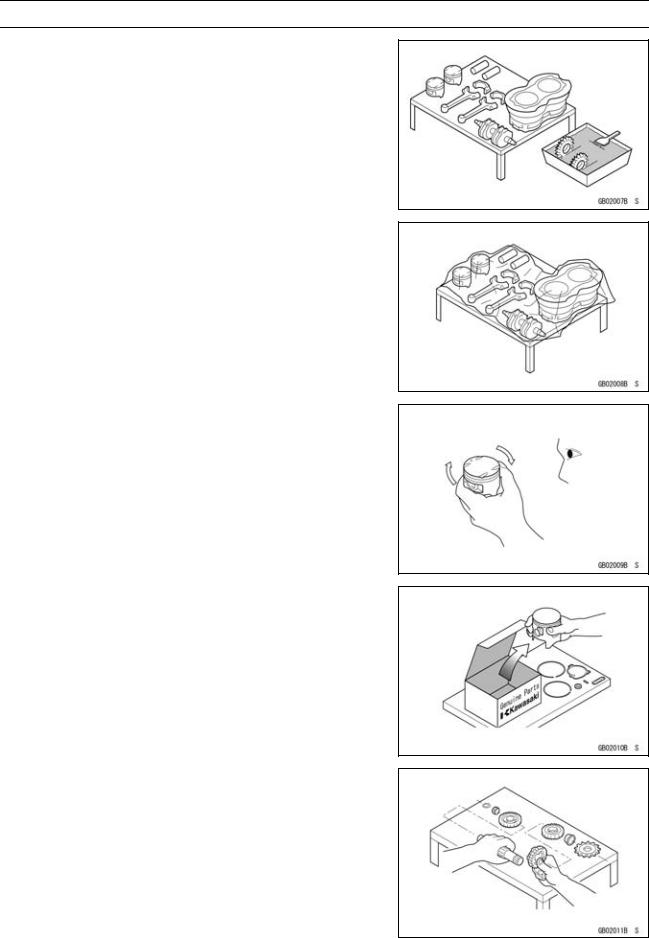
Arrangement and Cleaning of Removed Parts
Disassembled parts are easy to confuse. Arrange the parts according to the order the parts were disassembled and clean the parts in order prior to assembly.
Storage of Removed Parts
After all the parts including subassembly parts have been cleaned, store the parts in a clean area. Put a clean cloth or plastic sheet over the parts to protect from any foreign materials that may collect before re-assembly.
Inspection
Reuse of worn or damaged parts may lead to serious accident. Visually inspect removed parts for corrosion, discoloration, or other damage. Refer to the appropriate sections of this manual for service limits on individual parts. Replace the parts if any damage has been found or if the part is beyond its service limit.
Replacement Parts
Replacement parts must be KAWASAKI genuine or recommended by KAWASAKI. Gaskets, O-rings, oil seals, grease seals, circlips, cotter pins or self-locking nuts must be replaced with new ones whenever disassembled.
Assembly Order
In most cases assembly order is the reverse of disassembly, however, if assembly order is provided in this Service Manual, follow the procedures given.
1-4 GENERAL INFORMATION
Before Servicing
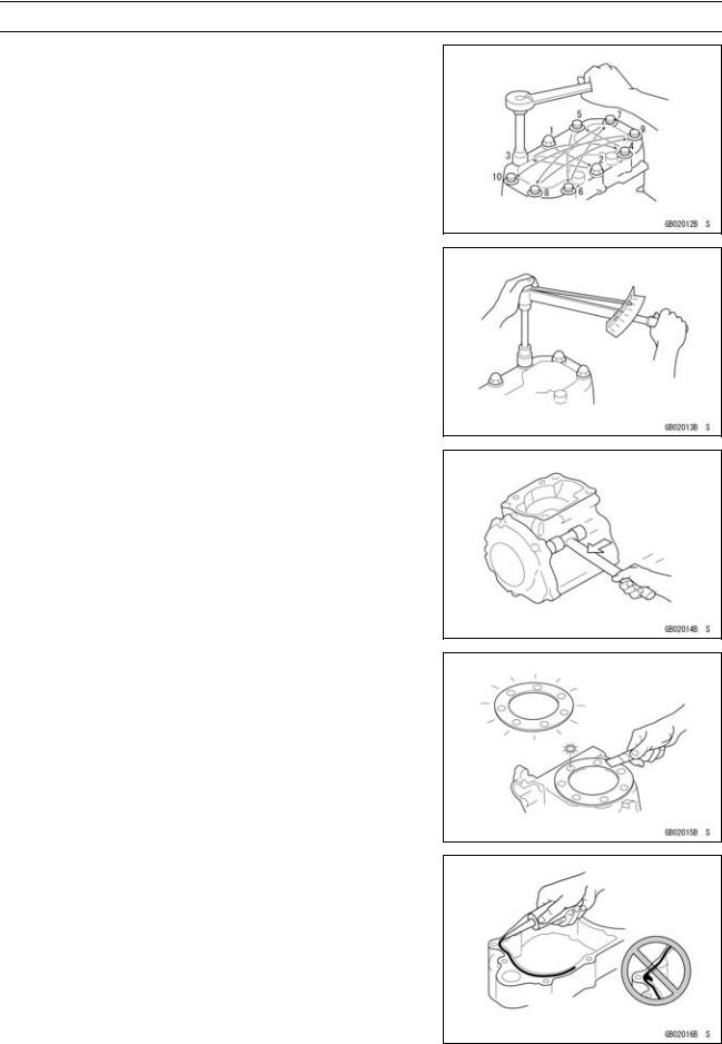
Tightening Sequence
Generally, when installing a part with several bolts, nuts, or screws, start them all in their holes and tighten them to a snug fit. Then tighten them according to the specified sequence to prevent case warpage or deformation which can lead to malfunction. Conversely when loosening the bolts, nuts, or screws, first loosen all of them by about a quarter turn and then remove them. If the specified tightening sequence is not indicated, tighten the fasteners alternating diagonally.
Tightening Torque
Incorrect torque applied to a bolt, nut, or screw may lead to serious damage. Tighten fasteners to the specified torque using a good quality torque wrench.
Force
Use common sense during disassembly and assembly, excessive force can cause expensive or hard to repair damage. When necessary, remove screws that have a non -permanent locking agent applied using an impact driver. Use a plastic-faced mallet whenever tapping is necessary.
Gasket, O-ring
Hardening, shrinkage, or damage of both gaskets and O-rings after disassembly can reduce sealing performance. Remove old gaskets and clean the sealing surfaces thoroughly so that no gasket material or other material remains. Install the new gaskets and replace the used O-rings when re-assembling.
Liquid Gasket, Non-permanent Locking Agent
For applications that require Liquid Gasket or a Non-permanent Locking Agent, clean the surfaces so that no oil residue remains before applying liquid gasket or non-permanent locking agent. Do not apply them excessively. Excessive application can clog oil passages and cause serious damage.
GENERAL INFORMATION 1-5
Before Servicing
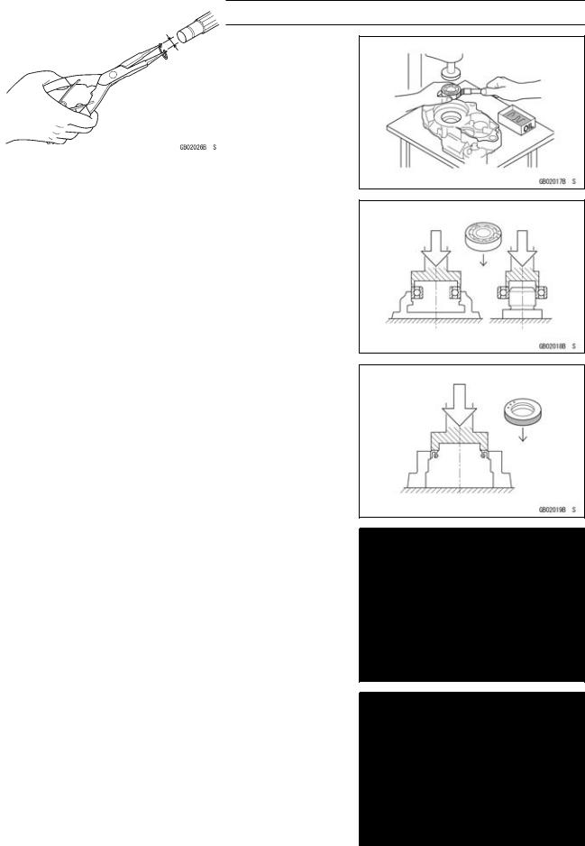
Press
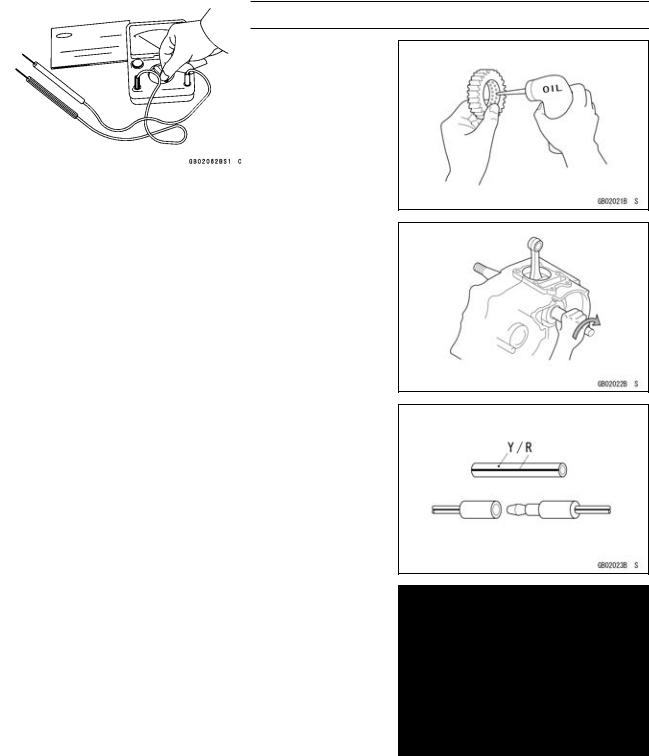
For items such as bearings or oil seals that must be pressed into place, apply small amount of oil to the contact area. Be sure to maintain proper alignment and use smooth movements when installing.
Ball Bearing and Needle Bearing
Do not remove pressed ball or needle unless removal is absolutely necessary. Replace with new ones whenever removed. Press bearings with the manufacturer and size marks facing out. Press the bearing into place by putting pressure on the correct bearing race as shown.
Pressing the incorrect race can cause pressure between the inner and outer race and result in bearing damage.
Oil Seal, Grease Seal
Do not remove pressed oil or grease seals unless removal is necessary. Replace with new ones whenever removed. Press new oil seals with manufacture and size marks facing out. Make sure the seal is aligned properly when installing.
Apply specified grease to the lip of seal before installing the seal.
Circlips, Cotter Pins
Replace the circlips or cotter pins that were removed with new ones. Take care not to open the clip excessively when installing to prevent deformation.
1-6 GENERAL INFORMATION
Before Servicing
Lubrication
It is important to lubricate rotating or sliding parts during assembly to minimize wear during initial operation. Lubrication points are called out throughout this manual, apply the specific oil or grease as specified.
Direction of Engine Rotation
When rotating the crankshaft by hand, the free play amount of rotating direction will affect the adjustment. Rotate the crankshaft to positive direction (clockwise viewed from output side).
Electrical Leads
A two-color lead is identified first by the primary color and then the stripe color. Unless instructed otherwise, electrical leads must be connected to those of the same color.
Instrument
Use a meter that has enough accuracy for an accurate measurement. Read the manufacture’s instructions thoroughly before using the meter. Incorrect values may lead to improper adjustments.
GENERAL INFORMATION 1-7
Model Identification
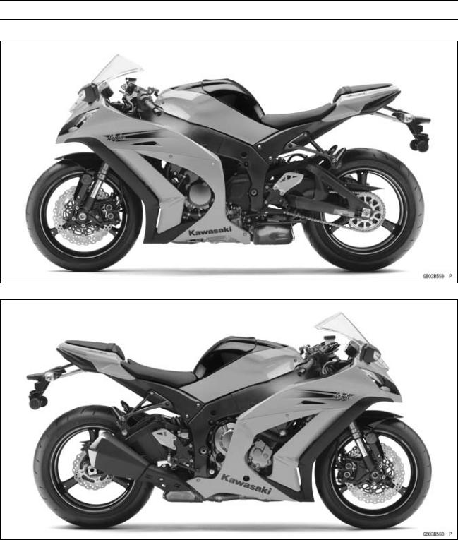
ZX1000JB (US and CA Models) Left Side View
ZX1000JB (US and CA Models) Right Side View
1-8 GENERAL INFORMATION
Model Identification
ZX1000JB (EUR Models) Left Side View
ZX1000JB (EUR Models) Right Side View
GENERAL INFORMATION 1-9
Model Identification
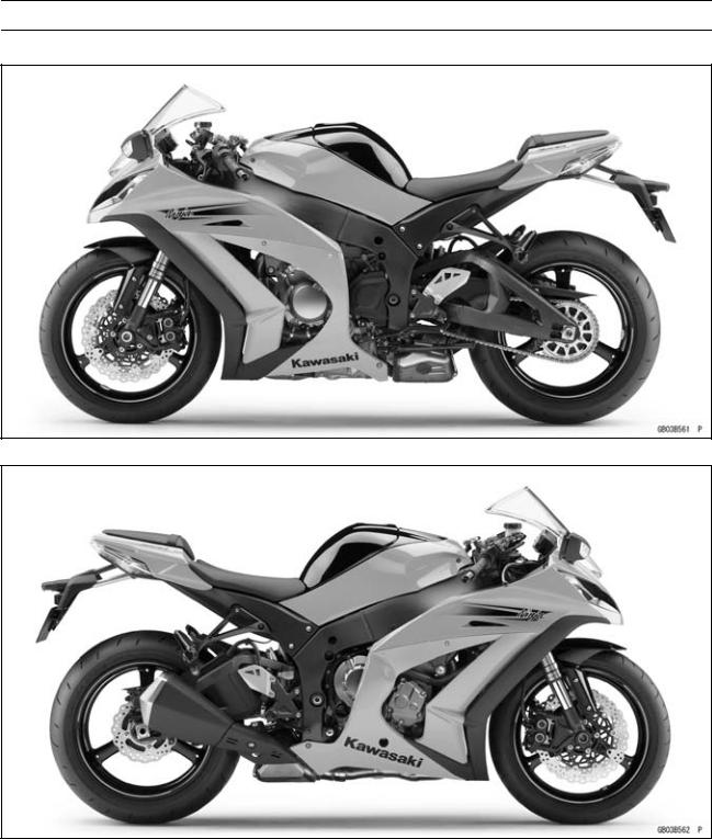
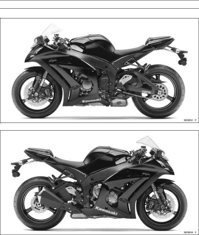
ZX1000KB (US and CA Models) Left Side View
ZX1000KB (US and CA Models) Right Side View

1-10 GENERAL INFORMATION
Model Identification
ZX1000KB (EUR Models) Left Side View
ZX1000KB (EUR Models) Right Side View
Frame Number |
|
Engine Number |
|
|
|
|
|
|
|
GENERAL INFORMATION 1-11 |
General Specifications |
|
|
|
|
|
Items |
ZX1000JB JD/KB KD |
Dimensions |
|
Overall Length |
2 075 mm (81.69 in.) |
Overall Width |
715 mm (28.1 in.) |
Overall Height |
1 115 mm (43.90 in.) |
Wheelbase |
1 425 mm (56.10 in.) |
Road Clearance |
135 mm (5.31 in.) |
Seat Height |
813 mm (32.0 in.) |
Curb Mass: |
|
(ZX1000J Model) |
198 kg (437 lb) |
Front |
103 kg (227 lb) |
Rear |
95 kg (209 lb) |
(ZX1000K Model) |
201 kg (443 lb) |
Front |
104 kg (229 lb) |
Rear |
97 kg (214 lb) |
Fuel Tank Capacity |
17 L (4.5 US gal) |
Performance |
|
Minimum Turning Radius |
3.4 m (11.2 ft) |
Engine |
|
Type |
4-stroke, DOHC, 4-cylinder |
Cooling System |
Liquid-cooled |
Bore and Stroke |
76.0 × 55.0 mm (3.0 × 2.2 in.) |
Displacement |
998 cm³ (60.9 cu in.) |
Compression Ratio |
13.0:1 |
Maximum Horsepower |
|
147.1 kW (200 PS) @13 000 r/min (rpm) |
|
|
(WVTA (78.2 H)) 78.2 kW (106 PS) @12 500 r/min (rpm) |
|
(SEA-B1/B2) 111 kW (151 PS) @10 000 r/min (rpm) |
|
(US, CA, CAL) – – – |
Maximum Torque |
112 N·m (11.4 kgf·m, 82.6 ft·lb) @11 500 r/min (rpm) |
|
(WVTA (78.2 H)) 78 N·m (8.0 kgf·m, 57.5 ft·lb) @5 200 r/min |
|
(rpm) |
|
(SEA-B1/B2) 106 N·m (10.8 kgf·m, 78.2 ft·lb) @10 000 r/min |
|
(rpm) |
|
(US, CA, CAL) – – – |
Fuel System |
FI (Fuel Injection), KEIHIN TTK47 × 4 |
Starting System |
Electric starter |
Ignition System |
Battery and coil (transistorized) |
Timing Advance |
Electronically advanced (IC igniter in ECU) |
Ignition Timing: |
|
( ZX1000JC/KC) |
10° BTDC @1 100 r/min (rpm) |
(ZX1000JD/KD) |
10° BTDC @1 100 r/min (rpm) 42.5° BTDC @10 500 r/min |
|
(rpm) |
Spark Plug |
NGK CR9EIA-9 |
Cylinder Numbering Method |
Left to right, 1-2-3-4 |
Firing Order |
1-2-4-3 |
|
|

1-12 GENERAL INFORMATION
General Specifications
Items |
ZX1000JB JD/KB KD |
Valve Timing: |
|
Intake: |
|
Open |
36° (BTDC) |
Close |
80° (ABDC) |
Duration |
296° |
Exhaust: |
|
Open |
74° (BBDC) |
Close |
39° (ATDC) |
Duration |
293° |
Lubrication System |
Forced lubrication (wet sump with oil cooler) |
Engine Oil: |
|
Type |
API SG, SH, SJ, SL or SM with JASO MA, MA1 or MA2 |
Viscosity |
SAE 10W-40 |
Capacity |
3.7 L (3.9 US qt) |
Drive Train |
|
Primary Reduction System: |
|
Type |
Gear |
Reduction Ratio |
1.681 (79/47) |
Clutch Type |
Wet multi disc |
Transmission: |
|
Type |
6-speed, constant mesh, return shift |
Gear Ratios: |
|
1st |
2.600 (39/15) |
2nd |
|
2.053 (39/19) |
|
3rd |
1.737 (33/19) |
4th |
1.571 (33/21) |
5th |
1.444 (26/18) |
6th |
1.348 (31/23) |
Final Drive System: |
|
Type |
Chain drive |
Reduction Ratio |
2.294 (39/17) |
Overall Drive Ratio |
5.197 @Top gear |
Frame |
|
Type |
Tubular, diamond |
Caster (Rake Angle) |
25° |
Trail |
107 mm (4.21 in.) |
Front Tire: |
|
Type |
Tubeless |
Size |
120/70 ZR17 M/C (58W) |
Rim Size |
J17M/C × MT3.50 |
Rear Tire: |
|
Type |
Tubeless |
Size |
190/55 ZR17 M/C (75W) |
Rim Size |
J17M/C × MT6.00 |
|
GENERAL INFORMATION 1-13 |
General Specifications |
|
|
|
|
|
Items |
ZX1000JB JD/KB KD |
Front Suspension: |
|
Type |
Telescopic fork (upside-down) |
Wheel Travel |
120 mm (4.72 in.) |
Rear Suspension: |
|
Type |
Swingarm (horizontal back-link) |
Wheel Travel |
140 mm (5.51 in.) |
Brake Type: |
|
Front |
Dual discs |
Rear |
Single disc |
Electrical Equipment |
|
Battery: |
|
(ZX1000J Model) |
12 V 6 Ah |
(ZX1000K Model) |
12 V 8.6 Ah |
Headlight: |
|
Type |
Semi-sealed beam |
Bulb: |
|
High |
12 V 55 W (quartz-halogen) × 2 |
Low |
12 V 55 W (quartz-halogen) |
Tail/Brake Light |
LED |
Alternator: |
|
Type |
Three-phase AC |
Rated Output |
30 A/14 V @5 000 r/min (rpm) |
Specifications are subject to change without notice, and may not apply to every country.

1-14 GENERAL INFORMATION
Technical Information-Sport-Kawasaki TRaction Control System (S-KTRC)
Overview
S-KTRC is a highly sophisticated system based on MotoGP racing technology. Unlike the KTRC system used on the GTR1400 ABS (Concours 14 ABS in N. America), which is designed to offer rider reassurance when traversing slippery surfaces, S-KTRC, is designed to maximize forward motion, allowing riding at the edge of traction.
The quickest acceleration requires a certain amount of slip, so in order to optimize traction, S-KTRC actually allows slip. The ideal slip ratio varies according to conditions. The system looks at a number of parameters to get an accurate real-time picture of what is going on: front and rear wheel speed (slippage), engine rpm, throttle position, slippage, acceleration, etc.
Using complex analysis, the system is able to predict when traction conditions are about to become unfavorable. By acting before slippage exceeds the range for optimal traction, drops in power can be minimized resulting in ultra-smooth operation.
There are three available modes that riders can set according to preference (and skill level). Each mode is able to accommodate a range of riding conditions. Of course, engine manageability is such that riders can opt to turn the system OFF without fear of making the bike uncontrollable.
By combining the setting with the power mode, the rider can choose various riding modes to suit the road conditions and riding skill.
The system becomes functional at 5 km/h (3.1 mph) or more. If a failure occurs in the system, the warning indicator light (yellow LED) and mode indicator symbol blink to let the rider know that the system stops functioning.
GENERAL INFORMATION 1-15
Technical Information-Sport-Kawasaki TRaction Control System (S-KTRC)
System Components
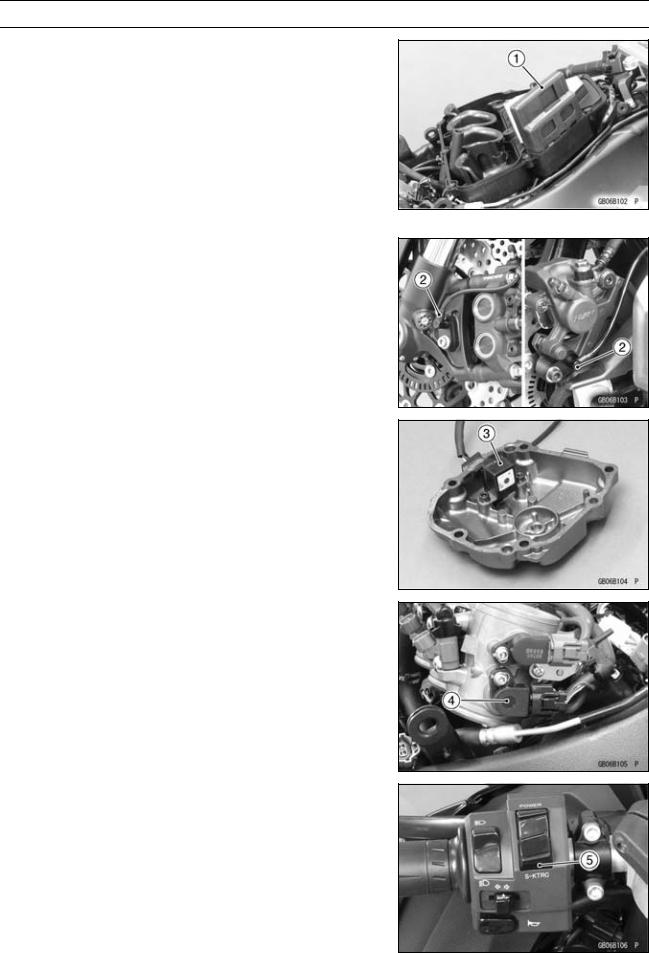
1. FI ECU
The FI ECU analyzes the motorcycle conditions based on the signals from the front/rear wheel rotation sensors and FI sensors (such as the crankshaft sensor and main throttle sensor), and controls engine power by reducing the number of ignition and retarding the ignition timing. The mode-switching signal is transmitted to the FI ECU by the CAN system via the meter ECU. If a failure occurs in the system, the FI ECU deactivates S-KTRC and displays the warning indication in the meter.
2. Wheel Rotation Sensor
The wheel rotation sensor converts front and rear wheel rotation speed to a pulse signal and transmits it to the FI ECU.
As for the KIBS (Kawasaki Intelligent anti-lock Brake System) equipped model, a pulse signal is transmitted via the KIBS ECU.
3. Crankshaft Sensor
The crankshaft sensor converts the engine speed to a pulse signal and transmits it to the FI ECU.
4. Main Throttle Sensor
The main throttle sensor converts the throttle position to a voltage signal and transmits it to the FI ECU.
5. S-KTRC Button
The mode-switching signal is transmitted to the meter ECU by depressing the S-KTRC button (0.3 0.4 sec.).
1-16 GENERAL INFORMATION
Technical Information-Sport-Kawasaki TRaction Control System (S-KTRC)
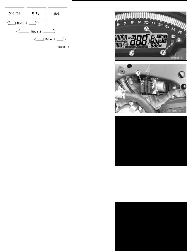
6. Multifunction Meter
The multifunction meter receives a mode-switching signal and displays the mode [A], and transmits it to the FI ECU by the CAN system.
When a failure occurs in the system, the multifunction meter displays the warning indication by blinking the warning indicator light (yellow LED) [B] and mode indicator symbol.
It also displays the S-KTRC operating conditions in the level indicator [C].
7. KIBS ECU
As for the KIBS equipped model, the front and rear wheel sensor signals are transmitted to the FI ECU via the KIBS ECU.
Mode-switching
Depress the S-KTRC button on the left handlebar switch to change the mode. The mode can be changed only when the throttle grip is closed completely.
The S-KTRC OFF can be selected only when the motorcycle is at a stop. Changing to mode 1 from S-KTRC OFF is possible while riding.
NOTE
○When changing the mode, stop the motorcycle.
○The mode is retained if the ignition switch is turned to OFF or if the battery is disconnected.
○When the ignition switch is turned to OFF, and then back to ON while S-KTRC is OFF, the system will automatically be set to mode 1.
○If the battery is disconnected and then reconnected while S-KTRC is OFF, the S-KTRC is set in mode 1.
Mode 1: S-KTRC least restrictive among the three modes. This makes lengthy drifts and wheelies possible when exiting tight corners.
Mode 2: There is more S-KTRC interaction compared to mode 1. This makes slight drifts possible when exiting tight corners.
Mode 3: S-KTRC intervenes to prevent the rear wheel from spinning whenever possible.

GENERAL INFORMATION 1-17
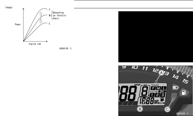
Technical Information-Power Mode
The rider can choose from three engine power modes to suit their preferences and road conditions. The FI ECU controls the engine power by adjusting fuel injection, air intake, and ignition timing. It enables three-mode selection: Full Power (Mode F), Middle Power (Mode M), and Low Power (Mode
L).
In addition, combining each mode with each S-KTRC setting allows the rider to have more choices to be able to interact with various conditions.
Power Mode Operation
To change the mode, close the throttle grip completely, and depress the power mode button [A] (0.3 0.4 sec.).
Power Mode Positions
NOTE
○The power mode setting is maintained when the ignition switch is turned OFF, or when the battery is disconnected.
1-18 GENERAL INFORMATION
Technical Information-Power Mode
Mode F: The highest engine power output is achieved. The rider can use the full power of the engine.
Mode M: The throttle response is less sharp compared to mode F. Depending on the throttle application, full power can be accessed temporarily.
Mode L: About 60% of the highest engine power output is achieved. The throttle response is mildest among the three modes.
The current mode selection is displayed on the power mode indicator [A] in the multifunction meter.
If a failure occurs with a FI related components such as a subthrottle or main throttle sensor, the warning indicator light (red LED) and FI warning symbol will go ON, and/or the S-KTRC indicator [B] and warning indicator light (yellow LED) [C] blink. The current mode cannot be changed at this time.
GENERAL INFORMATION 1-19
Technical Information-Kawasaki Intelligent anti-lock Brake System (KIBS/ZX1000K model only)
Overview
Kawasaki Intelligent anti-lock Brake System (KIBS) offers enhanced braking stability (ABS performance equivalent to the current model) to supersport models, which pitch more than most motorcycles and also offers high-precision front and rear brake pressure control (high-precision ABS) for sport riding.
Precise control of the ABS operation decreases kickback to the brake lever and brake pedal during braking compared to the conventional system.
In addition to the front and rear wheel sensors in a conventional ABS, KIBS monitors a number of parameters: front caliper hydraulic pressure and information from the FI ECU (engine speed, throttle position, gear position, and clutch actuation).
KIBS uses an all-new BOSCH hydraulic unit which was designed specifically for motorcycle use. The new design is small and light weight (45% less volume and 800g lighter than current units). The unit is located close to the motorcycle’s center of gravity, behind the engine cylinder and above the sprocket cover.
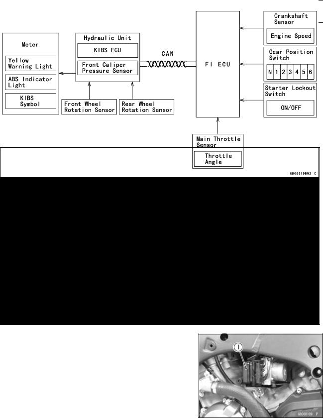
System Components
1. KIBS ECU
With input from the front and rear wheel sensors and front caliper hydraulic pressure, the KIBS ECU analyzes various conditions on the motorcycle, and with additional information from the FI ECU (engine speed, throttle position, gear position, and clutch actuation) precisely controls the brake caliper hydraulic pressure. As a result, brake force is generated to suit conditions. If there is no engine information from the FI ECU, the KIBS is deactivated and the warning is displayed in the meter; however, the conventional ABS function is maintained.
2. Wheel Rotation Sensor
The wheel rotation sensor converts the front and rear wheel rotation speed to a pulse signal and transmits it to the KIBS ECU and FI ECU.
1-20 GENERAL INFORMATION
Technical Information-Kawasaki Intelligent anti-lock Brake System (KIBS/ZX1000K model only)
3. KIBS Hydraulic Unit
The KIBS hydraulic unit consists of the hydraulic unit and KIBS ECU and has the front caliper hydraulic pressure sensor built-in.
When receiving a signal from the KIBS ECU, the hydraulic unit increases or decreases the front and rear brake hydraulic pressure.
The front caliper hydraulic pressure sensor always monitors the front caliper hydraulic pressure and transmits the hydraulic pressure change to the KIBS ECU.
4. FI ECU
The FI ECU transmits information from the crankshaft sensor (engine speed), the main throttle sensor (throttle position), the gear position switch (gear position), and the starter lockout switch (ON/OFF) to the KIBS ECU by the CAN system.
5. Multifunction Meter
When a failure occurs in the system, the multifunction meter displays the warning indication by turning ON the warning indicator light (yellow LED) [A] and KIBS symbol [B].
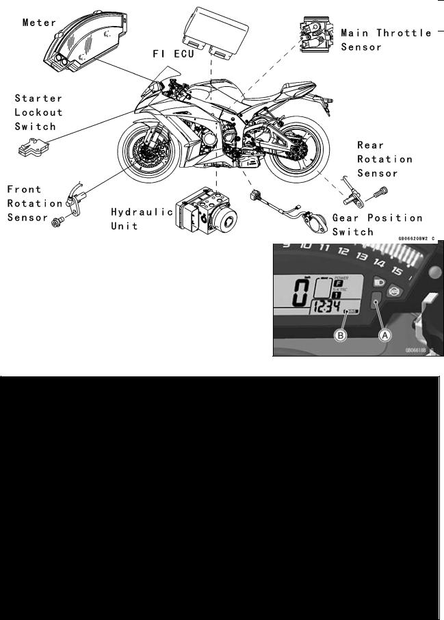
Related Parts Locations
Loading...