


Operating instructions – Part 1 |
UFS 925 |
Connection and set-up |
English |
Safety instructions - Important notes............. |
2 |
Product package............................................... |
5 |
Connection and set-up..................................... |
6 |
Front/rear view of the receiver |
|
(front flap open)................................................ |
6 |
Inserting batteries into the remote control........ |
8 |
Connecting the receiver ................................... |
9 |
TV connection .................................................. |
9 |
Audio connection............................................ |
10 |
Digital .................................................................... |
10 |
Analogue ............................................................... |
10 |
Connecting up the video/DVD recorder ......... |
10 |
Information about antenna connection and |
|
loop-through mode ......................................... |
11 |
First installation .............................................. |
12 |
Network/Internet access................................. |
46 |
Common Interface (CI)/Smartcard reader...... |
48 |
Inserting the HD+ card in the Smartcard reader.... |
48 |
Inserting the Smartcard and the CI Module........... |
49 |
Troubleshooting ............................................. |
50 |
Service............................................................. |
51 |
Technical appendix ........................................ |
52 |
Advanced connection example ...................... |
52 |
Technical data ................................................ |
53 |
Sat IF connection examples........................... |
54 |
Individual reception systems ................................. |
54 |
Community antenna network systems |
|
(4 x Sat IF)............................................................. |
54 |
Community antenna network systems |
|
(8 x Sat IF), multi-feed........................................... |
55 |
Community antenna network systems |
|
(16 x Sat IF), multi-feed......................................... |
55 |
OneCable single-cable systems............................ |
56 |
Connection examples for network |
|
functionality .................................................... |
58 |
DHCP (receiver): OFF........................................... |
58 |
DHCP (receiver): OFF........................................... |
59 |
DHCP (receiver): OFF........................................... |
60 |
DHCP (receiver): ON............................................. |
61 |
For your notes ................................................ |
62 |
Neu |
Vereint TV und Internet |
An Internet connection is required to use HbbTV and HD+ InterAktiv! See “Network/Internet access” after first installation.
If you do not know the configuration of your satellite reception system, contact your specialist dealer for the first installation of your receiver.
Safety instructions - Important notes
These two pages contain important information about operation, installation location and connection of the unit. Read these instructions carefully before setting up the device.
Mains cable
Make sure that the mains cable (power supply cable) is not damaged.
Danger! Units with a damaged mains cable must be disconnected from the mains
(unplugged at the mains power socket) and repaired by an electrical specialist before being used. Only use the power supply unit supplied (if available)!
Risk of fatal injury due to electric shock!
Cleaning
Disconnect the mains plug before cleaning the unit. Only use a dry cloth for cleaning and only clean the outer surface. Never open the casing of the unit.
Touching the parts inside the unit carries a risk of death due to electric shock!
Playing children
Make sure that children do not push any objects into the ventilation slots.
Risk of fatal injury due to electric shock!
Earthing
The antenna system must be earthed as specified or equipotentially
Warning! bonded.
EN 60728/11 and any national regulations must be complied with.
Risk of voltage surges due to lightning strikes!
Power supply voltage
Operate the unit only at the specified mains voltage (indicated on the rear of the unit or on the external power supply unit). The unit may only be connected to the mains and turned on once it has been connected to the
Warning!
Warning!
Do not 
 cover
cover

antenna and to the TV set or the cable network and PC.
If the mains voltage is too high, there is a risk of fire!
Moisture, direct sunlight, heat, naked flames
Protect the unit against moisture,
dripping and |
splashed water |
(do |
not place any |
filled objects |
such |
as vases on top of the unit). Do not place the unit close to a heater or expose it to direct sunlight and do not operate it in damp locations. Only use the unit in a moderate climate, not in tropical conditions! Do not place naked flames such as candles on top of the unit!
There is a risk of fire!
Batteries
If your unit was supplied with batteries (e.g. for the remote control), take care that the batteries are not exposed to excessively high temperatures, direct sunshine or fire. Exchange the batteries only with types that are identical or equivalent. Otherwise the batteries and also the remote control may be damaged. Also comply with the safety instructions stated on the batteries:
There is a risk of explosion!
Ventilation
The heat generated in this unit is adequately dissipated. However, the unit should never be installed in a cupboard or on shelves with inadequate ventilation. Never cover the cooling slots on the unit (e.g. with other equipment, magazines, tablecloths, clothing or curtains)!
2
Safety instructions - Important notes
Do not place any objects on top of the unit. Unless stated to the contrary in the “Connection and set-up” and “Installation” sections in the manual supplied, maintain a clearance of at least 10 cm above the unit, 2 cm to either side and 5 cm behind the unit, to allow the unobstructed dissipation of the heat generated.
There is a risk of fire!
Repairs
Ensure that any repairs to your unit are carried out by qualified personnel.
Caution! Opening the unit and attempting to repair it yourself will void all warranty
claims!
Improper work on the unit may jeopardise the electrical safety of the unit.
The manufacturer accepts no liability for accidents caused by the user opening the casing of the unit!
Connections
Incorrect wiring of the connections can lead to malfunctions or defects on the unit!
Periods of extended absence, thunderstorms, mains socket accessibility
In order to disconnect the unit from the mains completely, the mains plug must be unplugged from the wall socket! Therefore install the unit close to a mains socket and make sure this socket is accessible at all times, so that you can disconnect the unit from the mains if necessary.
If you are away for an extended period, and during thunderstorms, always switch the unit off at the mains and unplug it from the socket. This also applies to the other equipment connected to the unit. Isolation from the cable network is also recommended. Note any timer programming (receiver) and turn the unit on again promptly before the recording time.
Installation location
All electronic equipment generates heat. The temperature rise of this unit does however lie within the permissible range. Sensitive furniture surfaces and veneers may become discoloured by the effects of constant heat over time. The feet of the unit can also cause colour changes to treated furniture surfaces. If necessary, place the unit on a suitable stable and flat base!
Electronic equipment is not domestic waste - it must be disposed of properly in accordance with directive 2002/96/EC OF THE EUROPEAN PARLIAMENT AND THE COUNCIL dated 27th January 2003 concerning used electrical and electronic appliances.
At the end of its service life, take this device to a designated public collection point for disposal.
Spent batteries are special waste!
Do not throw spent batteries into your domestic waste; take them to a collection point for spent batteries!
3
Safety instructions - Important notes
Product return/original packaging
Please keep the original packaging in case you need to return the product at any time. The receivers are fragile due to their construction and are only adequately protected by the original packaging. If the receiver is not shipped correctly the guarantee/warranty on it will be voided.
Fan/ventilation slots on the unit
Make sure that the fan at the rear of the unit and the ventilation slots on the unit are not blocked or covered in any way. The unit may otherwise overheat. Adjust the fan speed to the temperature conditions in the receiver.
Warning! There is a risk of fire!
Instructions on how to set the fan can be found in the chapter “Main menu”, “Settings”, “Basic settings”, “Fan settings”.
Switching the receiver off
Before you disconnect the receiver from the mains, you must switch it to the standby mode by pressing the standby button (on/off) on the remote control. In standby mode, any changed or new data that is broadcast will be saved by the receiver. As soon as the receiver is in the standby mode, it can be disconnected from the mains at any time.
You must not disconnect the receiver from the mains while it is in operation! This can lead to a loss of data and corruption of the software.
Miscellaneous
The information in this operating manual was correct at the time of going to print. We reserve the right however to make changes at any time and without prior notice. If new software is released for your receiver, and this affects the information in the operating manual (e.g. changes to the menus and/or functions), and if we believe it necessary we will make a new operating manual available for download under “www.kathrein.de”.
Make a note of the receiver's basic settings (these are set during the first installation), so you can restore them if necessary!
Please be aware of your responsibility towards your fellow man. Keep the manual for any questions that arise later, and if the building passes to another owner, pass it on to the new owner.
4
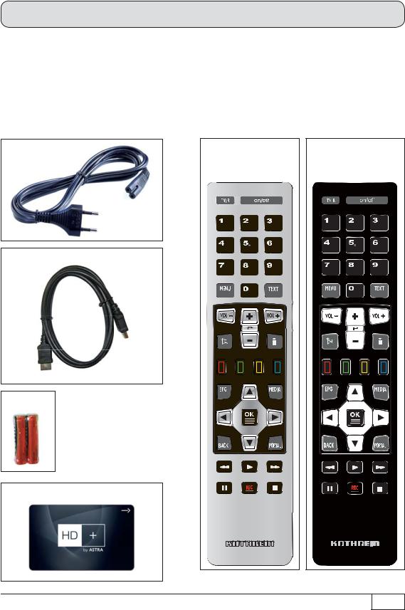
Product package
■UFS 925
■Remote control RC 676 or 675
■HDMI cable
■Mains cable
■HD+ Smartcard (already inserted in card reader)
■2 batteries AAA 1.5 V
■Operating instructions (part 1 and part 2)
■Safety instructions (multilingual)
The accessories supplied may differ in appearance from those illustrated!
Mains cable |
Remote control for |
Remote control for |
|
the 1000 GB version |
the 500 GB version |
HDMI cable |
|
|
Batteries |
|
|
HD+ Smartcard |
|
|
|
|
5 |

Connection and set-up
Front/rear view of the receiver (front flap open)
11 |
10 |
|
27 |
8 |
9 |
26 |
|
7 |
|
|
|
6 |
5 |
|
25 |
|
4 |
23 |
24 |
|
|
22 |
21 |
|
3 |
19 |
20 |
|
|
18 |
17 |
|
2 |
|
16 |
|
1 |
|
|
|
|
14 |
15 |
|
|
13 |
12 |
6

Connection and set-up
Front view (flap open)*): |
Rear view: |
|||
1. |
On/Off button (operation/stand-by) |
12. |
LNB 2 input (IF2 IN) |
|
2. |
TV/radio button |
13 |
LNB 1 input (IF1 IN) |
|
3. |
256 x 64 pixel full graphic display |
14. |
Network connection (Ethernet) |
|
4. |
Media button (recording archive, |
15. |
2 x USB 2.0 ports (USB-A connectors) |
|
|
as on remote control) |
16. |
HDMI connection |
|
5. |
Back button (back/cancel, |
|||
17. |
Scart socket for TV connection |
|||
|
as on remote control) |
|||
|
18. |
Scart socket for VCR/AUX connection |
||
6. |
Multi-function control dial |
|||
19. |
Optical data stream output (SPDIF/ |
|||
7. |
USB 2.0 port |
|||
|
Sony Philips Digital Interface Format) |
|||
|
|
|
||
8. |
SD card reader |
|
for Dolby Digital AC 3 audio |
|
9. |
Common Interface for two CI+/CI modules |
20. |
Audio outputs (L/R) – cinch sockets |
|
|
for Pay-TV cards **) |
21. |
Electrical digital data stream output |
|
10. |
Built-in Smartcard reader |
|||
|
(SPDIF/Sony Philips Digital Interface |
|||
|
for HD+ Smartcard |
|
Format) for Dolby Digital AC 3 audio |
|
11. |
A button to release each CI module |
22. |
3 x Cinch connections for component |
|
|
|
|
outputs YUV labelled = Y/Pb/Pr |
|
|
|
23. |
Video output (CVBS) |
|
|
|
24. |
S-Video output |
|
|
|
25. |
Fan |
|
|
|
26. |
Mains power cable |
|
|
|
27. |
On/Off switch ***) |
|
*) |
Flap is opened by gently pulling on the top right-hand edge of the flap |
**) |
CI modules and Smartcards are not included with this product |
***) The unit is not fully disconnected from the mains (see the sections “Safety instructions - Important instructions” and “Periods of extended absence, thunderstorms, mains socket accessibility”)
HDMI = High-Definition Multimedia Interface (digital interface for video and audio) |
7 |
|

Connection and set-up
Inserting batteries into the remote control
Remove the cover on the rear of the remote control. Insert the two batteries supplied into the remote control. Ensure correct polarity of the batteries; the + and – markings as indicated inside the battery compartment. Slide the cover back onto the housing until it locks in place.
To open:
Gently press here and pull backwards
8

Connection and set-up
Connecting the receiver
If you do not know the configuration of your satellite reception system, contact your specialist dealer.
Connect the Sat IF inputs on the receiver to the satellite reception system.
Use coaxial cable with an F standard connector (see illustration on right).
Conventional DiSEqC™ system
TV
HDMI
Scart
TV connection
Connect the satellite receiver (HDMI or alternatively TV Scart socket) and the TV set using a HDMI or Scart cable (see the connection example above).
9
Connection and set-up
Audio connection
Digital
There are two ways you can access the digital audio.
HDMI
The stereo audio is transmitted to your TV set via the HDMI interface. If your TV set also supports Dolby Digital, you can also receive the Dolby Digital audio via the HDMI interface (providing it is broadcast by the channel provider). On this issue refer to the operating manual for your TV set.
SPDIF Dolby Digital output (electrical/optical)
The SPDIF outputs are intended for the connection of a Dolby Digital system (see “Advanced connection example” in the technical appendix). Connect the SPDIF output (electrical or optical) to the Dolby Digital system using an appropriate cable.
Analogue
If you want to play the sound on your Hi-Fi system, connect the audio cinch sockets to the input sockets on the Hi-Fi system, using an appropriate cable (see “Advanced connection example” in the technical appendix).
Connecting up the video/DVD recorder
Connect the satellite receiver (VCR/AUX Scart socket) to the video recorder/DVR using a Scart cable. To play back a DVD, i.e. output the signal from the DVR through the receiver on the TV set, the TV set must also be connected to the receiver with a Scart cable. This is necessary because the video signal from the VCR Scart socket of the receiver is not looped through/forwarded to the HDMI output of the receiver.
Tip!
If you are recording via an external video recorder/DVD, remember not to operate the receiver during recording, otherwise all the on-screen displays will appear on your recording.
If the receiver is started by means of a timer recording, there will be no picture on your TV set. Only when the standby button (On/Off) is pressed will a TV picture be visible or the receiver begin operation.
10 |
SPDIF = Sony Philips Digital Interface Format (digital output for Dolby Digital AC 3 audio) |
|
Connection and set-up
Information about antenna connection and loop-through mode
To enable you to exploit all the reception and recording features of your twin-DVR HDTV Sat receiver, such as
1.recording one programme and simultaneously viewing any other programme or zapping through the channels, and
2.recording two different programmes at the same time,
The two tuner inputs of the satellite receiver must each be supplied with a dedicated satellite signal from the antenna system/Sat outlet (unless connected to a single-cable system).
The receiver tuner inputs are factory preset in the installation menu to work with two separate Sat antenna connections.
In cases where only one antenna connection is available (with the exception of single-cable systems), “Loop-through” must be selected for “Tuner 2 Connection type” in the “First installation” settings
(see the section “First installation”). Press the button to access the “Tuner Configuration” menu option, then select “Settings” and “First installation”. Go through step by step until you get to the tuner configuration. You can define the settings here. Though a restriction on this is that with Tuner 2 you can only receive the additional channels of the plane currently set by Tuner 1 (e.g. Horizontal High). From this point on only the channels that can be selected are displayed in the channel list.
This will only work when receiving one satellite, not with multi-feed reception! (Multi-feed reception: simultaneous reception of several satellites)
If you want to operate your UFS 925 on a single-cable system, please refer to the connection examples for OneCable systems (see “Technical appendix”, “Examples of single-cable systems”).
11
Connection and set-up
First installation
Before you start to use the UFS 925, read the chapters “Safety instructions - Important instructions”, “Important information” and “Connection and set-up” through to the item “First installation”.
Do not connect the unit to the mains until all installation work has been properly carried out.
The guidance provided in the “First installation” section assumes that the receiver has been properly connected as per the “Safety instructions - Important information” and “Connection and set-up” sections through to the “First installation” section.
Required buttons on remote control for first installation:
... |
Number input |
(green) |
Proceed to the next step |
|
in the first installation |
||||
|
|
|
|
|
(red) |
Go back one step in the |
|
Confirm the changed |
|
values/setting; |
||||
first installation |
||||
|
|
|
call up the submenus |
|
|
Select/change individual |
|
|
|
menu parameters, navigation |
|
|
Cancel entry, go back
First switch your TV set on and select the AV-/HDMI input you have used to connect the receiver to your TV set. Switch on the receiver at the power switch on the rear of the unit. Now perform the first installation. If you have any questions or encounter problems, contact your specialist dealer.
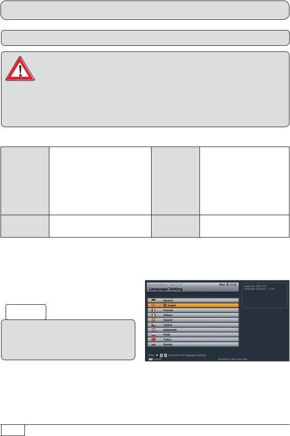
The following on-screen display appears:
Tip!
Always check the bar at the bottom of the on-screen display. This provides information on what to do next.
Use the buttons to select the desired menu language for your UFS 925 and confirm your
selection using the button. The selected language is indicated with a tick. The following languages are available: German, English, French, Italian, Spanish, Czech, Dutch, Polish Turkish and Russian.
12

Connection and set-up
Press the (green) button to move to the next menu.
The following on-screen display appears:
Use the buttons here to select the basic settings for the video and audio output of the receiver to the TV set.
For this, refer to the operating manual for your TV set and take care to select only those settings that your TV set can process.
Video Output via
Select the connection on the receiver to which you have connected your television. Either
HDMI/YUV |
or |
SCART |
|
|
|
|
|
|
|
|
|
HDMI/YUV Resolution
Here you can select the video resolution that will be output at the TV set. Either
-1080p (resolution 1920 x 1080, full-screen images)
-1080i (resolution 1920 x 1080, half-screen images)
-720p (resolution 1280 x 720, full-screen images)
-576p (resolution 720 x 576, full-screen images) or
-Automatic
Force 576i (must be supported by the TV set otherwise you will not see a TV picture)
You can only/only need to set this setting if you have selected the setting “Automatic” for “HDMI/YUV Resolution”. If for a programme
TV aspect ratio
Here you can select the TV picture format. Either
-4:3 or
-16:9
Picture format
Select the type of screen display, depending on your setting for the TV aspect ratio:
-TV aspect ratio “4:3”: Pan & Scan or Letterbox
-TV aspect ratio “16:9”: Always 16:9 or Automatic
13
Connection and set-up
that is transmitted in the format 720 x 576 (standard TV), the original format is to be transmitted to the TV set, select the “On” setting. If the setting is “Off”, the programme may be automatically scaled-up to the HDTV format 720p by the receiver.
HDCP (not adjustable)
Show 4:3 Event
Here you can select the type of screen display mode for 4:3 broadcasts on a 16:9 TV set. Either
-Normal (Pillar Box)
-Stretched (full screen) or
-Zoom in (Pan & Scan)
Audio Format via HDMI
Here you can select the type of audio signal that is transmitted by the HDMI interface. Select the signal that your TV set can process:
-Decoded PCM or
-SPDIF format
Auto Dolby Digital Output
Here you can select whether the receiver should automatically select the Dolby Digital soundtrack (if this is transmitted).
Important instruction for picture output using “YUV”:
The “YUV” output option can only be used if “RGB” is not selected as the output signal for the TV Scart socket!
In this case, select “Y/C” or “CVBS” as the output signal for the TV Scart socket.
TV Scart output
Select the type of video signal at the TV Scart socket here. Select the signal that your TV set can process.
-CVBS – composite video (Composite Video, Blanking, and Sync) signal or
-RGB – Red/Green/Blue signal or
-Y/C – S-Video signal (luminance/colour)
VCR-SCART output
Select the type of video signal at the VCR Scart socket here. Select the signal that your external recorder can process.
-CVBS – composite video (Composite Video, Blanking, and Sync) signal or
-Y/C – S-Video signal (luminance/colour)
Auto Dolby Digital Output
Here you can select whether the receiver should automatically output the Dolby Digital signal (if this is transmitted).
14

Connection and set-up
Press the (green) button to move to the next menu.
The following on-screen display appears:
The settings for the antenna configuration should be performed by a specialist engineer for this reception system.
Tip!
If your receiver is connected as in the connection example (see illustration above), only one change/selection is necessary in the rest of the first installation. If you are not familiar with the details of your reception system, note the following:
In many cases the satellite reception system is a DiSEqC™1.0 system. This type of system is preset. Confirm the current on-screen displays using the (green) button. You then select, using the buttons the required satellites in the satellite selection (in Germany mostly ASTRA 19.2° East) and confirm the selection using the button. Confirm the rest of the
on-screen displays during the first installation using the (green) button. This process cannot damage your reception system. If there is no TV picture at the end of the first installation, contact your specialist dealer.
You should perform the tuner configuration/make changes yourself only if you are fully familiar with the particulars of your reception system.
15
Connection and set-up
You can set up the tuner configuration for the following types of reception systems:
-DiSEqC™1.0
-DiSEqC™1.1
-Polar antenna (DiSEqC™1.2/ DiSEqC™1.3)
-LNB only or
-OneCable system
If your reception system is a single-cable system, go to the “OneCable System” option in this section and continue from there.
Before you start configuring the tuner you must first set both the “Tuner 2 Connection type” and “Tuner 2 Signal Configuration” settings.
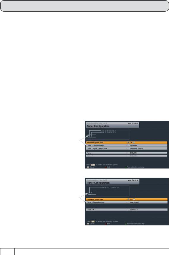
Tuner 2 Connection type
Select the type of connection for Tuner 2 here. The currently selected setting is shown graphically in the connection example at the top left of the screen. Either:
Separated:
The second tuner input of the receiver (LNB2 IN) receives its own signal input (i.e. there is a direct connection between the antenna socket and tuner input 2). See example illustration on the right.
Loop-through:
The current signal received at the Tuner 1 loop-through output is looped through the second tuner input of the receiver (LNB2 IN). In this case, the second tuner can only receive the channel level currently being received by the first tuner. See example illustration on the right.
See also “Information about antenna connection and loop-through mode” earlier in this section.
16
Connection and set-up
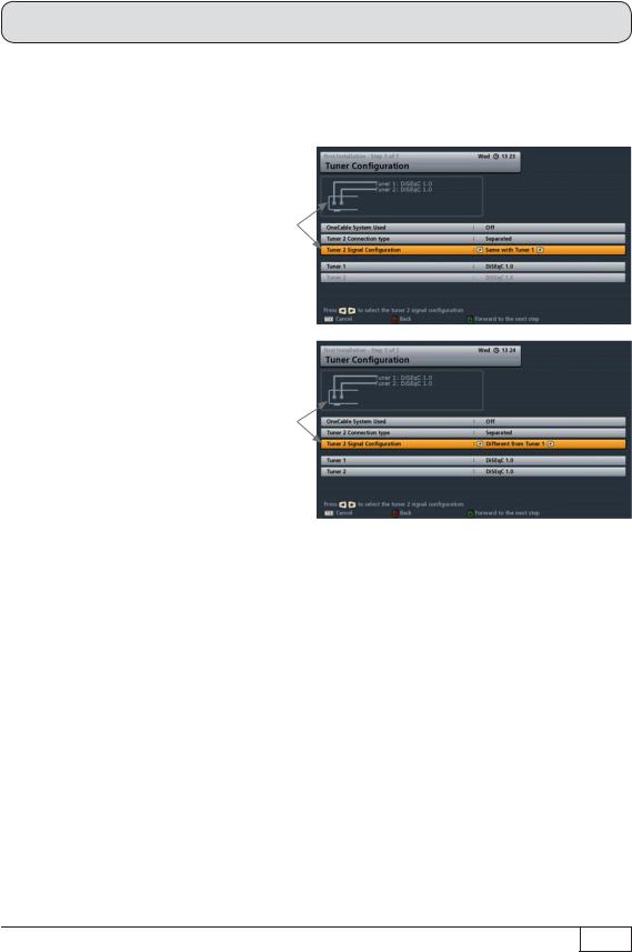
Signal configuration for Tuner 2 (only for “Separated” connection type)
Select the signal configuration for Tuner 2 here. The currently selected setting is shown graphically in the connection example at the top left of the screen. Either:
Same as Tuner 1:
Both tuners are connected to the same signal source. See example illustration on the right.
Different from Tuner 1:
The two tuners are connected to different signal sources (separate cables from the LNB). See example illustration on the right.
The following configuration options are available for:
Tuner 2 connection type “Loop-through”:
All settings are made on Tuner 1. The second tuner is fed from the first tuner.
Tuner 2 connection type “Separated”/Tuner 2 Signal Configuration “Same as Tuner 1”:
All settings are made on Tuner 1. The settings for the second tuner are automatically taken from the first tuner.
Tuner 2 connection type “Separated”/Tuner 2 Signal Configuration “Different from Tuner 1”:
All settings must be made separately for the two tuners.
Use the buttons to set the parameters “Tuner 2 Connection type” and “Tuner 2 Signal Configuration” appropriate to the setting for your reception system.
Continue as described in the first installation for the type of reception you have selected.
17
Connection and set-up
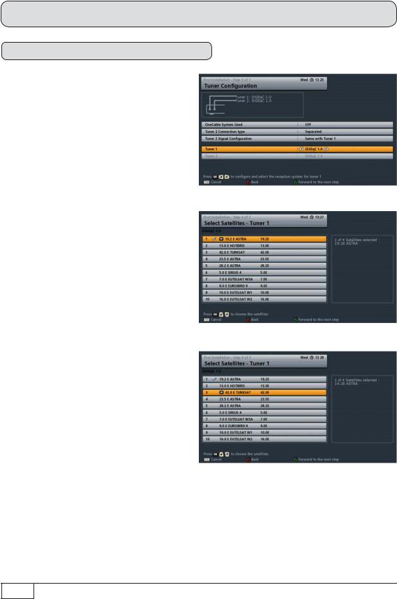
DiSEqC™1.0
Press the (green) button.
The following on-screen display appears:
Select Satellites - Tuner 1
Here, you can select up to four available satellites to be included in the signal on Tuner 1. Select the satellite you want and
confirm your selection with the button. The selected satellites will be identified with a tick.
When you have completed all settings, press the (green) button.
18
Connection and set-up
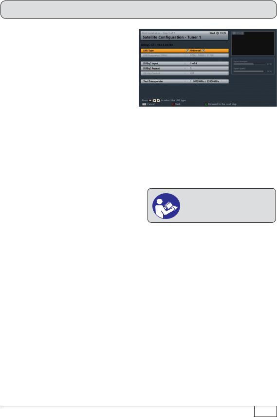
The following on-screen display appears:
Satellite Configuration - Tuner 1
Define the settings for the first satellite for
Tuner 1 here.
LNB Type:
If your reception system does not have a universal LNB, use the buttons to select the LNB types that are used in your reception system. You can choose from the following LNB types:
-Universal,
-Simple or
-User-defined
LNB frequency (MHz):
You only need to specify this data if your LNB type is not “Universal”. The data required differs for the settings “Simple” and “User-defined”.
Refer to the documentation for your LNB or seek assistance from a specialist engineer.
- |
Selection “Simple” LNB: |
|
Use the number pad to enter the LNB frequency |
- |
Selection “User-defined”: |
To enter the required low, high and limit frequencies press |
|
|
|
|
the button. The entry is made using the number pad |
DiSEqC™ input: |
|
|
|
- |
1 of 4: |
For the first satellite on the tuner (item A on the system) |
|
- |
2 of 4: |
For the second satellite on the tuner (item B on the system) |
|
- |
3 of 4: |
For the third satellite on the tuner (item C on the system) |
|
- |
4 of 4: |
For the fourth satellite on the tuner (item D on the system) |
|
19
Connection and set-up
DiSEqC™ repeat:
The setting for how often the DiSEqC™ |
Refer to the documentation for |
|||
command must be |
repeated |
depends |
your reception system or seek |
|
on the configuration |
of your |
reception |
assistance from a specialist |
|
system. |
|
|
engineer. |
|
- |
Off |
DiSEqC™ command is not repeated |
|
|
- |
1 |
DiSEqC™ command is repeated once |
|
|
- |
2 |
DiSEqC™ command is repeated twice |
|
|
- |
3 |
DiSEqC™ command is repeated three times |
||
22 kHz control:
You only need to specify this data if your LNB type is “Simple”. The 22 kHz signal is needed to switch LNBs when using multi-feed reception and to switch between Low and High band.
-On
-Off
Test Transponder:
Select the “Test Transponder” field. Here you can select a transponder for checking whether your settings are correct using the signal strength bar and signal quality bar.
When you have completed all settings for this satellite, press the (green) button.
If you have selected more than one satellite (max. four) for Tuner 1, the receiver will automatically skip to the settings for the second satellite. Now define the settings for the second satellite, followed by the third and fourth satellites as required, in the same way as described for the first satellite.
Once all settings for all the satellites that you selected have been completed, the receiver will automatically skip to the settings for the second tuner (assuming that for the second tuner you selected the connection type “Separated” and set the signal configuration to “Different from Tuner 1”). If this is the case, now define the settings for the second tuner in the same way as you did for the first tuner.
Once you have completed the settings for both tuners and the satellites assigned to them, the receiver will automatically display the screen for the channel search. Continue the first installation with the “Channel Search” section.
20
 Loading...