


Translation of the |
- English - |
original operating manual |
|
CAP upgrade kit
HDS 910

GENERAL
Chère Cliente, Estimado cliente,
F
Vous pouvez obtenir un manuel d‘installation en français chez notre réprésentant en votre pays (http://www.kathrein.de/include/kontakte_groups_eng.cfm?kontinent=1&gruppe=SAT) ou le télécharger de notre page d‘ouverture (http://www.kathrein.de/en/sat/index.htm).
E
Para obtener la versión española de nuestro manual de instalación, contacte nuestros representantes en su país (http://www.kathrein.de/include/kontakte_groups_eng.cfm?kontinent=1&gruppe=SAT) o bajela de nuestra página de Internet (http://www.kathrein.de/en/sat/index.htm).
COMPANY ADDRESS AND ACCREDITED REPRESENTATIVE
KATHREIN-Werke KG |
Distinguished Businessman Prof. Dr. Dr. h. c. Kathrein, |
Anton-Kathrein-Straße 1 - 3 |
MBA |
PO Box 10 04 44 |
Personally liable |
83022 Rosenheim |
Managing Director of KATHREIN-Werke KG |
2

HDS 910 COMPONENTS / SCOPE OF SUPPLY
HDS 900 (rear view)
UFS 940sw (front view)
See the UFS 940sw operating manual for a rear view of the receiver together with explanation of functions and operating instructions.
SCOPE OF SUPPLY
The HDS 910 upgrade kit consists of:
•HDS 900 control unit
•1 x coaxial cable 9 m long (for use in connection with CAP 210/310),
•1 x 8-pin cable adapter 0.15 m long (for use in connection with CAP 100)
•1 x 2-pin cable adapter 0.15 m long (for use in connection with CAP 100)
•4 chipboard screws 4 x 40
•UFS 940sw HDTV-DVB-S receiver with connecting cables, infrared sensor and infrared remote control
•HDS 910 upgrade kit user instructions
•UFS 940sw satellite receiver operating manual
3

CONTENTS (INSTALLATION MANUAL) |
|
GENERAL................................................................................................................................. |
2 |
HDS 910 COMPONENTS / SCOPE OF SUPPLY .......................................................................... |
3 |
CONTENTS (INSTALLATION MANUAL) ..................................................................................... |
4 |
PROPER USE ........................................................................................................................... |
6 |
SAFETY INSTRUCTIONS - IMPORTANT NOTES......................................................................... |
8 |
INSTALLATION AND CONNECTION........................................................................................... |
9 |
EXCHANGING THE CONTROL UNIT ........................................................................................ |
9 |
VIEWS OF THE HDS 900 CONTROL UNIT ................................................................................... |
9 |
DISCONNECTING THE CONNECTIONS TO THE OLD CONTROL UNIT ........................................... |
10 |
INSTALLING THE NEW CONTROL UNIT.................................................................................... |
10 |
CONNECTING THE CONTROL UNIT ........................................................................................ |
12 |
INSTALLATION OF THE UFS 940SW ...................................................................................... |
15 |
LAYING CABLES AND CONNECTING THE TURNTABLE............................................................... |
20 |
CONNECTING TO THE UFS 940SW ......................................................................................... |
20 |
FUNCTIONAL INSTRUCTIONS FOR CONNECTION TO THE ON-BOARD POWER SUPPLY.................. |
21 |
4

CONTENTS (OPERATING MANUAL) |
|
CAP 610 OPERATING MANUAL............................................................................................... |
22 |
IMPORTANT INFORMATION FOR CAP BEFORE SETUP .......................................................... |
23 |
REMOTE CONTROL.............................................................................................................. |
23 |
FIRST INSTALLATION ............................................................................................................. |
24 |
CAP MENU (TURNTABLE ANTENNA SETTINGS) ..................................................................... |
28 |
CALLING UP THE CAP MENU ................................................................................................ |
28 |
RESETTING THE CAP SYSTEM (TURNTABLE ANTENNA) (RESET)......................................... |
28 |
INPUTTING THE CAP GPS POSITION .................................................................................... |
29 |
TO MOVE THE ANTENNA MANUALLY .................................................................................... |
29 |
ELEVATION......................................................................................................................... |
30 |
LNB TILT/SKEW ................................................................................................................... |
30 |
STOP ON SIGNAL ................................................................................................................ |
30 |
MOVE TO THE AZIMUTH (ROTATE THE ANTENNA) .................................................................... |
30 |
MOVE CAP TO PARK POSITION.............................................................................................. |
31 |
CAP SETTINGS..................................................................................................................... |
31 |
ELEVATION BORDER AND ELEVATION OFFSET ........................................................................ |
31 |
SEARCH SPEED.................................................................................................................. |
31 |
ALIGNMENT (SATELLITE SEARCH) ........................................................................................ |
32 |
CHANNEL (SATELLITE) SELECTION/PROGRAMMING THE TIMER .......................................... |
33 |
CHANNEL SELECTION FROM THE CHANNEL LIST ................................................................ |
33 |
CHANNEL SELECTION FROM THE CHANNEL LIST (SORTED BY SATELLITE)......................... |
34 |
CHANGE OF LOCATION.......................................................................................................... |
35 |
PARK...................................................................................................................................... |
36 |
PARKING THE TURNTABLE ................................................................................................... |
36 |
SPECIAL MESSAGES FROM THE TURNTABLE ....................................................................... |
37 |
DISPOSAL INSTRUCTIONS..................................................................................................... |
41 |
FOR YOUR NOTES ................................................................................................................. |
42 |
5
PROPER USE
PROPER USE (USE FOR THE INTENDED PURPOSE)
The HDS 910 upgrade kit is intended for upgrading the following Kathrein products:
Product |
|
Current status |
|
|
Status after upgrade |
|||
|
Ana- |
Digital |
HDTV |
Recording |
Ana- |
Digital |
HDTV |
Recording |
|
logue |
|
|
(USB) |
logue |
|
|
(USB) *) |
|
|
|
|
|
|
|
|
|
CAP 100 **) |
x |
|
- |
- |
- |
x |
x |
x |
CAP 200 |
|
x |
- |
- |
- |
x |
x |
x |
CAP 210 |
|
x |
- |
- |
- |
x |
x |
x |
CAP 300 |
|
x |
- |
- |
- |
x |
x |
x |
CAP 301 |
|
x |
- |
- |
- |
x |
x |
x |
CAP 310 |
|
x |
- |
- |
- |
x |
x |
x |
The CAP units listed in the table are used for reception from satellites of digital TV and radio channels (prior to the upgrade the CAP 100 can receive only analogue). The automatic positioner acts as a turntable for the Kathrein BAS 60 antenna.
The turntable can be used to receive digital TV and radio signals in the frequency range from 10.70 to 12.75 GHz; the antenna cannot receive terrestrial signals (e.g. DVB-T).
After the upgrade, the turntable can be used only in conjunction with the UFS 940sw DVB-S receiver.
In conjunction with this receiver, the turntable provides fully automatic alignment of the BAS 60 to receive digital satellite signals. The turntable is designed for use on stationary caravans or motor homes.
Any use other than that specified above will invalidate the warranty or guarantee.
When any of the above CAP units is upgraded by means of the HDS 910 upgrade kit, no changes to the turntable and/or the BAS 60 are necessary! The existing cabling can also still be used!
A BAS 50 planar antenna in use hitherto must be replaced with a BAS 60 (BN 216195) (this applies only in connection with the CAP 100)!
*) This function can be used only when an external USB storage medium (such as an external hard disk with a USB connection *)) is connected and is formatted in the “FAT32” or “EXT2” format. The USB storage medium that is connected may not have more than three partitions, since the receiver cannot manage and use more than three partitions. Tested only with hard disks from the Kathrein product range (see also: www.kathrein.de → Service → FAQs)
**) BAS 50 must be replaced with a BAS 60 (BN 216195)
6

PROPER USE
The following circumstances result in the loss of all warranty and liability claims towards the manufacturer:
•Improper installation
•Structural changes or interference with the components and mounting accessories in the set, which could endanger both the mechanical and functional reliability
•Improper or forcible opening of the components
•Disregard of the further installation and safety instructions in these user instructions and inn the original manual for the respective CAP product
Note: The maximum permissible speed for vehicles with a receiver unit mounted on the roof is 130 km/h. Before commencing a journey, the satellite dish must always be lowered into horizontal position (park position).
The turntable may be operated in an ambient temperature range of -10 °C to +40 °C. Operating the system outside this range may result in malfunctions or damage to the system. When choosing the location for installation of the UFS 940sw, ensure there is adequate ventilation.
The system may only be installed by qualified pecialist personnel!
To prevent hazards during installation, operation or when driving on public highways, the instructions and information in this manual must be strictly adhered to. Proper performance of the upgrade of the system is a pre-requisite for conformity with the corresponding standards.
This is documented in advance by the CE mark and the declaration of conformity in the appendix of the respective CAP user manual.
7
SAFETY INSTRUCTIONS - IMPORTANT NOTES
Proper installation and safety
Essential information
The correct execution of the upgrade (for instance the electrical connection work) is important for safety.
Modifications to the electrical installations in the vehicle should only be carried out by a specialist in vehicle electrics. Do not make any unauthorised changes to the turntable.
Cables
Lay all cables such that nobody can tread on them or trip over them.
To prevent parasitic induction or interference emissions, when extending the antenna cable use 75 Ω coaxial cable with a screening factor of at least 75 dB.
If you tied the cables together with wire or similar materials, remove this to prevent the risk of fire!
When connecting the power cables (receiver and turntable) to the vehicle electrical supply, make sure that the cable polarity is not reversed.
If the cable polarity is reversed there is a risk of thermal overload and damage to components when the equipment is powered up!
Never remove or bypass the fuse in the cable – cable fire hazard!
8
INSTALLATION AND CONNECTION
REQUIRED TOOLS AND EQUIPMENT
•Flat-bladed screwdriver for M5 screws
•Cross-head screwdrivers for M3 and M5 screws
EXCHANGING THE CONTROL UNIT
Before starting any installation work, it is essential you disconnect all the units concerned from the mains. Risk of fatal injury due to electric shock!
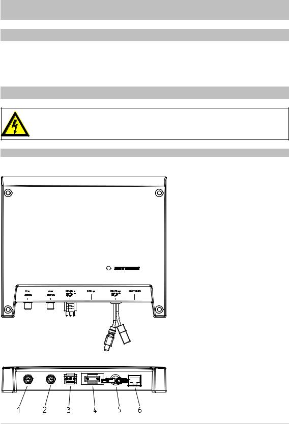
VIEWS OF THE HDS 900 CONTROL UNIT
Plan view
Connection side (listing from the left): |
|
1. |
F socket for connection to the turn- |
|
table |
2. |
F socket for connection to the UFS |
|
940sw satellite receiver |
3. |
Connection plug for the overall |
|
power supply |
4. |
Fuse (10 A) *) |
5. |
Connections for the power supply |
|
to the turntable (the turntable must |
|
not be powered via a separate |
Rear View |
power supply unit!) |
6. |
Connection socket for the control |
|
cable from the turntable |
*) |
Theonlyfusethatmaybefittedisa10A |
|
flat fuse supplied by Elschukom, with |
|
the article number 162.6385.5102 |
|
or an equivalent replacement type. |
9

INSTALLATION AND CONNECTION
DISCONNECTING THE CONNECTIONS TO THE OLD CONTROL UNIT
•Mark the coaxial cable that comes from the turntable to the control unit (port: “IF IN”), so that it will not later be confused with the coaxial cable that runs to the receiver.
•Now disconnect all connections to the control unit
•Remove the old control unit
INSTALLING THE NEW CONTROL UNIT
The four existing screw sockets (see diagram on the next page) allow you to attach the control unit to a solid flat surface.
In addition, the following points should be taken into account:
•The wall thickness at the installation location must be at least 12 mm, as otherwise the screws will break through on the other side or damage the surface
•Ensure that the cupboard or storage compartment in which the unit is housed is adequately ventilated, to prevent a build up of heat. Carpet-covered walls are unsuitable for installation
•Take care when tightening the screws not to damage any cables etc. behind or in the wall
•The control unit is designed exclusively for installation in dry, interior locations. The installation location must be protected against moisture.
•The cable lengths must be taken into account when choosing the installation location
•The connecting cables must be provided with strain reliefs
Connections and fusing of the unit:
All cables for connection to the control unit are connected at the rear of the unit (see also “Views of the HDS 900 control unit” in this section). When selecting the installation location, allow sufficient clearance at the rear of the unit for these cables and their plugs.
The plug-in fuse is also located at the rear. This fuse (for the type see “Views of the HDS 900 control unit” in this section) should be accessible even after installation, so that it can easily be exchanged if required.
Under no circumstances use countersunk-head screws for installation (see diagram on the right), since these can damage the screw sockets on the control unit. Wherever possible, use the wood screws supplied with the upgrade kit.
10

INSTALLATION AND CONNECTION
Use of other screws:
If because of the installation location or factors associated with it, the screws supplied cannot be used, refer to the diagram alongside when selecting the screws to be used. This shows you the cross-section area of the screw sockets on the control unit and shows which screws (diameter, screw head profiles etc.) can be inserted into the control unit support.
Air circulation
Cable ties *)
To prevent inadvertent disconnection of the power cables, secure them in accordance with DIN EN 1648-1 and -2. Ensure the cables are fitted with strain relief!
*) When upgrading a CAP 100 system, the 8-pin cable adapter and the power supply adapter should be used as shown. To prevent inadvertent disconnection of the plug connectors, we recommend they are secured with a cable tie or insulation tape, as shown above!
11

INSTALLATION AND CONNECTION
Marking out the screw / drill points at the installation location:
Accurately mark out the screw / drill points at the installation location.
The casing of the HDS 900 control unit is identical to the control unit for the CAP 200/300/301 turntables. If necessary you can use the same securing holes.
INSTALLATION
Secure the control unit at the installation location previously selected and prepared.
Do not force it, and take care that not to damage either the screw sockets, the control unit itself or any cables that are already attached to the control unit!
CONNECTING THE CONTROL UNIT
•Connect the coaxial cable (that comes from the turntable) to the “IF IN” port
•Now connect the other cables to the new control unit
If any cable connection cannot be made because the plug or socket does not match, there are two adaptor cables included in the upgrade kit!
Avoid laying the cables across sharp edges and secure the cables against possible chafing points.
The fuses in the cable and in the control unit must never be bridged – cable fire hazard!
12

INSTALLATION AND CONNECTION
Connection example for a caravan
Control unit HDS 900
|
*) |
|
|
|
|
Brown |
White |
Green |
|
|
*) |
|
NOTE! |
|
|
|
|
||
|
|
|
Do not connect. |
|
|
|
|
Option not available! |
|
|
|
|
The antenna must be lowered |
|
|
|
|
before driving away. |
|
|
|
|
• Switch on the receiver. |
|
|
|
|
• |
Select HDP menu. |
|
UFS 940sw HDTV receiver |
|
• |
Select park function and |
|
|
|
confirm. |
|
|
Recommended |
*can be obtained through |
||
|
mains unit * |
|
||
|
|
customer service ESC |
||
|
DF1765 ZIG |
|
||
|
|
|
||
*) |
For a CAP 100 system, use the |
|
|
|
|
cable adapters supplied |
|
|
|
13

INSTALLATION AND CONNECTION
Connection example motor home
Connection example motor home 12 V battery connection
Control unit |
HDS 900 |
|
|
|
|
*) |
|
|
|
|
Brown |
White |
Green |
|
|
*) |
|
|
|
|
Battery |
|
|
|
|
10.9 V-13.8 V |
Ignition |
||
HDTV-Receiver UFS 940sw
*) Bei CAP 100-Anlage die beigelegten Kabeladapter verwenden
14
 Loading...