


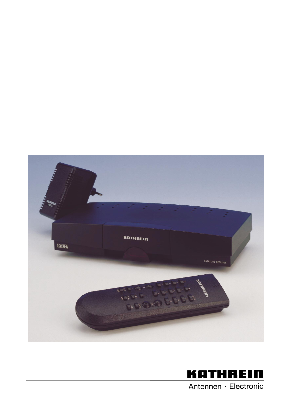
UFD 345
Operating manual
Kathrein Satellite Receiver
UFD 345
Order No.: 260 411

Contents
2
Inhalt
Controls, displays and connections................................................................................ 3
View of front panel with inf r ar ed s ens or , rear panel and r em ote control handset ....................................... 3
Front panel and infrar ed s ens or................................................................................................................ 4
Rear panel connections............................................................................................................................ 4
Remote control handset keys................................................................................................................... 4
Safety instructions............................................................................................................ 5
Important notes r egar ding oper ation......................................................................................................... 5
Important notes on s iting and installation.................................................................................................. 6
Connecting up and putting into operation...................................................................... 7
Installing the rec eiv er ............................................................................................................................... 7
Infrared sensor......................................................................................................................................... 7
Connecting up the unit ............................................................................................................................. 7
Inserting batteries into remote control....................................................................................................... 9
Receiver operation.......................................................................................................... 10
Switching the unit on ...............................................................................................................................10
Switchover between TV and radio mode..................................................................................................10
Selecting a programme ...........................................................................................................................10
Adjusting volume, balanc e and tone........................................................................................................11
Muting the sound.....................................................................................................................................11
Stereo-/Mono- Channel c hangeov er........................................................................................................12
Video recorder playback ( V CR) ...............................................................................................................12
SAT/TV changeover................................................................................................................................12
Operating the rec eiv er without remote control ..........................................................................................12
Swapping, sorting and inser ting programmes ..........................................................................................12
Displaying the Info m enu and pr ogr am m e ov er v iew.................................................................................13
Picture optimis ation when reception is weak............................................................................................14
Programming TV programmes....................................................................................... 15
Tuning in TV programm es.......................................................................................................................15
The “Video” menu ...................................................................................................................................15
Decoder menu ........................................................................................................................................17
Programme name ...................................................................................................................................17
The “Audio” menu ...................................................................................................................................18
Programming radio programmes................................................................................... 19
Tuning in radio programmes....................................................................................................................19
The “Radio” menu ...................................................................................................................................19
Initial settings............................................................................................................... ... 20
Calling the initial setup menu...................................................................................................................20
OSD language ........................................................................................................................................21
LNB supply voltage .................................................................................................................................21
LNB supply voltage in st andby ................................................................................................................21
Programme select ion ..............................................................................................................................21
On Screen Displays (OS D)......................................................................................................................21
Oscillator f r equenc y ................................................................................................................................22
DiSEqC menu.........................................................................................................................................23
22 kHz signal ..........................................................................................................................................24
Tone burst and DiSEqC signal.................................................................................................................24
Switching over remote control’s command set.........................................................................................25
Features........................................................................................................................... 26
Specifications ..................................................................................................................27
Menu structure................................................................................................................ 29
Connection examples / Service note............................................................................. 32
Drilling template..............................................................................................................33

Controls, displays and connections
3
Bedienelemente, Anzeigen und Anschlüsse
This section contains a brief description of all the control elements, displays and
connections. The key symbols presented here are also used when describing the
operating sequences.
View of front pa nel
View of rear panel
Remote co ntrol hand se t

Controls, displays and connections
4
Front panel Rear panel connections
1
Location slot for infrared sensor
2
Detachable infrared sensor
Receiver for infrared signals from the remote control.
The detachable infrared sensor allows the receiver to be in-
stalled hidden from view. All that is necessary is for the in-
frared sensor to be within the reception area of the infrared
signals from the remote control.
3
On/Off indicator (r ed LED )
In standby the indicator goes out
4
Program me s ele ction keys
Step- by-step programme selection (upwards and down-
wards).
Switch-on from standby by pressing both buttons simulta-
neously.
Switchover from TV- to radio mode by pressing both but-
tons simultaneously. .
1
Satellite IF signal input and
output of LNB supply voltage
2
Connecting socket for infrared sensor (Western 8-way)
3
Scart socket, TV connection
4
Scart socket, VCR connecti on
5
Scart socket, decoder connection
6
Connecting socket for voltage supply
12 ... 24 V DC
Remote control handset keys
Functio n 1:
On/Off (Standby ),
Attention: no mains isolation results!
Functio n 2:
Resetting from setup menu into normal operation
Key to call up picture optimisation menu if reception is
poor
to
Numer ic keys 0 - 9 for programme selection and
frequency entries
Functio n 1:
Command set changeover
Functio n 2:
Blanking of video signal (in setup mode)
Functio n 1:
Volume control
Functio n 2:
Selecti on of in div i du al men u en tr i es in set up m od e
Functio n 1:
Switchover to radio mode
Functio n 2:
Calls up men u for radio settin gs
(with
in succession)
Functio n 1:
Calls up the Info menu
Functio n 2:
Calls up menu for “Pro gr am m e slot swa pp ing, in-
sertion an d co py in g”
(with
in succession)
Functio n 1:
Steps through programmes either up or down
Functio n 2:
Changing data in setup mode
Functio n 1:
Mutes the sound
Functio n 2:
Calls up men u for au di o se tti ngs
(with
in succession)
Functio n 1:
Saves the chosen settings
Functio n 2:
Primary key for calling the separate setup menus
(e.g. video settings)
Unassigned Stereo/Mono- (2 channel) changeover
Functio n 1:
Selects TV/SAT mode
Functio n 2:
Calls up menu for video settings
(with
in succession)

Safety instructions
5
Sicherheitshinweise
The following section c ontains important information relating to operation, place of
installation and connect ing- up of the receiver. Read these notes carefully before
putting the unit into operation.
Important notes regarding operation
Extended absence/Thunderstorms
During periods of extended abs enc e or at the onset of thunderstorms always dis -
connect the unit from the supply , or withdraw the mains plug if the power supply
unit is used. This also applies to any other equipment attac hed.
Mains lead
Make certain that t he mains lead (power s upply lead) is undam aged. Never put the
unit into operation if the mains lead is damaged.
Cleaning
Withdraw the PSU mains plug before cleaning the unit. Use a dry cloth for c lean-
ing.
Children-at-play
Pay attention that c hildr en do not insert objects into the vent ilation slots. There is a
risk of mortal danger due t o elec tric shock.
Repairs
On no account remove the housing cover s inc e there are dangerous voltages in-
side the unit that may be contac ted. The unit must only be opened by qualified
specialists, s o allow them to carry out any repairs or adjustm ents to your r ec eiv er .
Unauthorised opening ent ails los s of guarantee.
The electrical safety of the unit can be affected by improper tam per ing with it
The manufactur er ‘s liability ex c ludes ac c idents occurring to the user when the unit
is opened.

Safety instructions
6
Important notes for siting and installation
Place of installation
Every electronic dev ic e gener ates some heat. The rise in temperatur e, however ,
lies within safe limit s . Never theless, this does not rule out t he possibilit y of slight
colour changes to sensitive furniture surfac es and veneers ov er time due to the
constant effect of heat.
In conjunction with treated furniture surfaces , the unit‘s rubber feet can likewise
give rise to changes in colour . Where necessary, place the unit on a suit able pad.
Ventilation
The heat that is generat ed in this unit is dissipated quite adequat ely . Never install
the receiver in a cabinet , shelf or rack with inadequate ventilation. Never close-off
the openings on the unit t hat are intended for heat dissipation.
Do not place objects on top of the unit . Maintain a clearance of at least 10 cm
above the unit so that the heat gener ated within the unit is convect ed away without
obstruction.
Mains voltage
Run the receiver only f r om a 12 –24V d.c. volt age s upply or from 230 V / 50 Hz
when using the mains pack supplied.
The unit is not to be connected t o the mains until after all the installation work has
been completed.
Humidity
Protect the unit agains t humidity, drips and splashes.
Solar radiation/heat
Do not place the receiver close t o r adiators nor expose it to direct sunlight.
LNB supply voltage
If the feeder system (LNB) is supplied wit h an ex ternal supply voltage and the LNB
supply voltage is not us ed for polar ity switchover (e.g. Kat hr ein s ingle- c able feeder
system UAS 330), the receiver‘s LNB supply must be set to “OFF”(refer to section:
“Initial settings, LNB supply voltage“).
There is a risk that the rec eiv er may s uff er damage if the change-over is not carried
out.

Connecting up and putting into operation
7
Anschluß und Inbetriebnahme
A sample configurat ion is to be found in section: “Connection example“ .
Attention!
Do not connect the unit t o the mains supply until after the installat ion wor k has
been carried out properly..
Please take note of guidance in sec tion: “Safety- and Inst allation Instructions”
Installing the receiver
The UFD 345 satellite receiv er is s uitable for mobile use in motor homes or cara-
vans, but can also serve as a fix ed station in the home.
Place of installation
The modern, elegant des ign of the receiver with its modest dimensions m eans it
can be placed in visual range, on t op of t he TV s et, for ex ample. In this case, insert
the infrared sensor into the locating slot on the front of the rec eiv er and run the ca-
ble to the rear via the cable channel on the bottom of the receiver (see below).
Connect the Western plug to the Western socket (2).
Due to its modest dimensions , however, the receiver can also be placed conc ealed
from view behind the TV set. Alt er natively, the receiver can be mounted on the
wall. For this, t her e is a drilling t em plate for the required drill holes at the end of the
guide. Cut the template out if required. In this case, the infrar ed s ens or is sited
separately.
Infrared sensor
The detachable infrar ed s ens or r ec eiv es the signals from the remote control and
passes them on to the receiver v ia the cable. As a result, it allows the sensor and
receiver to be sit ed separat ely . Consequently, the receiver c an be sited outside the
reception range (line of s ight) of the remote control, thus saving on spac e.
Connection of the sens or to t he receiver is v ia the 8-way Western plug, which you
should connect to t he Western s oc k et (2) on the rear of the receiver.
For optimum working, the infrared sensor should be sited at a clear ly v is ible s pot
near the TV set
Connecting up t he un it
Power supply
With mobile use, the rec eiv er s hould be c onnec ted directly to the vehicle‘s on-
board supply (12 ... 24 V) using t he adaptor cable included (adaptor cable with uni-
versal plug for cigarette lighter or vehicle socket out let and inner hollow conductor
plug).

Connecting up and putting into operation
8
Connect inner hollow conductor plug to the power supply socket (6) .
Caution!
If the power supply cable is m odified or a different one is used, it is ess ential t o
check for correct polarit y . Incorrect polarity will result in damage to the receiver.
For fixed applicat ions us e the acc om pany ing
power supply unit 230 V~/16 V =.
Satellite signal connection
•
Connect the Sat IF input of t he r ec eiv er to the satellite receiving system.
•
For the connection use a coax ial c able with an F-type connecting plug.
If the F connector is not yet f itt ed to the cable:
•
Insulate the cable as indic ated in the following illustration, and
•
Carefully screw the F connector onto the cable end until it is firmly seated on
the cable.
Attention!
Do not use any tools to screw the F plug onto the cable or to tighten to the F
socket. Put the connectors on hand-tight only.
Attention!
When fitting the plug, m ak e cert ain that none of the fine wires of the braided shield
makes contact with the inner c onduc tor giving rise to a short-c ircuit .
Receiving system presets
Presetting car r ied out for the control signals was for conventional receiving sys-
tems, thus 14/18 V for polarit y s witching and 22 kHz switching signal for satellite
selection in the case of multifeed receiving systems .
If DiSEqC or tone-burst switching matrices are to be used in the receiving system,
the setting must be select ed for "DiSEqC" signal or "Tone Burst” in the init ial s etup
menu at submenu “DiSEqC“.
For this, refer to sect ion: “Initial settings, DiSE qC m enu“ .
Also take note of the technic al guide for the matrices.

Connecting up and putting into operation
9
TV and video recorder connection (VCR)
•
Connect-up the sat ellite receiver (TV Scart socket ) and TV set with a Scart ca-
ble.
If your TV set has stereo capability , a Scart connection allows you to rec eiv e the
sound in stereo.
•
Connect-up the video rec or der and s atellite receiver (VCR Scart soc k et) again
using a Scart cable.
Decoder connection
You can also connect-up a dec oder to t he r ec eiv er for P ay-T V program m es.
No further setting is nec es s ar y for decoders that require a video signal and supply
a switching signal, such as Premiere decoder and Videocrypt decoder, for exam-
ple..
Important
With decoders that do not supply a s witching voltage, the receiver m us t be pro-
grammed appropriately beforehand (see “The video menu” s ection in c hapter “Pro-
gramming TV programmes“).
Also take note of the decoder spec ification!
•
Using a Scart cable connect- up the decoder to the decoder Scart socket .
Inserting batteries into remote control handset
•
Remove the cover on the rear of t he remot e c ontrol hands et.
•
Insert both of the batteries supplied into the remote c ontrol hands et.
Make certain that t he batt er ies ar e ins er ted with the correct polarity!
•
Replace the cover again.
Note
Exhausted batt er ies ar e special waste and should not be disposed of wit h house-
hold refuse. Instead, hand them in to a collection centre f or used bat teries!
Receiver operation
10
Bedienung des Receivers
In this chapter you learn how to select TV and radio programmes using your re-
ceiver, and how to adjust t he v olum e and s et up ot her func tions.
Switching th e unit on
•
Once the supply voltage is c onnec ted the unit goes into standby mode.
•
The
key on the remote contr ol is used t o switc h between standby and
normal operation. O per ation is shown by means of a red LED indicator in t he
infrared sensor.
•
The last programm e slot s elec ted is tuned in (last-status memory).
Switching between TV and radio mode
Your receiver allows you to receive TV programmes or radio programmes .
After switching on, the receiver is in either the TV mode or the radio mode (de-
pending on the mode when switched of f).).
In TV mode, the programme slot indicator in the on-screen display (OSD) begins
with "P". In radio mode, the screen is blanked out and the on-screen display begins
with "R
..
“.
•
Press the
key on the remote control handset to switch between TV- and
radio mode.
Note
In the initial setup menu, a continuous on-screen display of the radio programme
slot can be selected independent of the TV setting (see sect ion: “Initial settings, On
Screen Displays “).
Selecting a programme
•
Use the numeric keys
... to select the desired programme directly.
Example for a three-digit entry (with setting “free pr ogr amme selec tion”):
Selection of program m e s lot 147
•
1 is entered, program m e slot 1 appear s
•
4 is entered, program m e slot 14 appear s
•
7 is entered, program m e slot 147 now appear s .
or
•
Use the
keys to step through the progr am m es in succ ession.
After the programm e changeover, the programme slot and program m e name are
superimposed on the screen for approximately three seconds.

Receiver operation
11
Note
With the setting “ 2- or 3-digit programme selection” ther e is a s witch to the desired
programme after approxim ately 3 seconds. Digits can be ent er ed dur ing this time
period.
With the setting “fr ee pr ogr am m e select ion“ , the receiver switches to the corr e-
sponding programme slot im m ediately after each input. (see exam ple abov e) .
In the initial setup menu, a continuous on-screen display of the programme slot can
be selected (see section: “Initial settings, On Screen Display s “ ) .
Adjusting volume, balance and tone
•
If you press one of the
keys the following menu appears f or adjus tment
of the volume, balance, tone (treble and bass), stereo-width and pseudo-stereo:
!9ROXPH
$$
$$$
$$
$$$
$$$
$$$
$$$
$$
$$
$$$
$$$
$$$
$$$
$$$
$$$
$$
$$
$$
$$
$
%DODQFH
$
$
7UHEOH
$
$
%DVV
$
$
6WHUHR ZLGWK
$
$
3VHXGR6WHUHR 2))
With the
keys or the key you can select the respect iv e m enu entry
and then makes changes wit h the
keys.
The settings are not oper ative at the VCR Scart socket in order not to disturb v ideo
recordings.
The on-screen display is removed again after approximately 3 seconds.
Note
In the menu entry “Stereo Widt h" the stereo base width can be adjusted independ-
ently.
“Pseudo-Stereo" c an be us ed to sim ulate a “stereo-like” effect with m ono pro-
grammes, and should t hus only be activated with mono reception.
The “pseudo-ster eo” eff ec t can be s im ulated if a stereo programme is switched to
mono.
Muting the so un d
•
Press the
key.
The sound is muted, allowing you t o m ak e a phone call undist ur bed, for example.
•
Press the
key again to turn the sound back on.
Note
Mute is not operative at the VCR Scart soc k et.
 Loading...