


 Loading...
Operating Manua
UFD 170
DVB-S Receiver
and
Turntable

Foreword
Dear customer
This operating manual is intended to assist you in making optimum use of the comprehensive functions of your new DVB combi receiver and the turntable. We have tried to make the operating instructions as easy as possible to understand, and to keep them as concise as possible. To help you understand particular specialist terms that cannot be translated, we have added a short glossary at the end of the manual
The power switch is an environmentally friendly feature. If you will not be watching the television for a longer period, you should therefore disconnect your equipment from the power supply to save energy. For shorter breaks, you can switch the equipment to standby on the remote control, which uses only a minimal amount of energy
We hope you will have a good reception and gain a lot of enjoyment from your new DVB caravan receiver and automatic positioner
Your
KATHREIN Team
f you should experience any unexpected problems with your UFD 170/ turntable, please contact your specialist dealer or our hotline
KATHREIN-Werke KG |
ESC (Electronic Service Chiemgau) |
Technical Customer Support |
Factory repair centre |
Tel: +49(0) 8031 184700 |
Tel: +49(0) 8641 9545-0 |
Fax: +49(0) 8031 184676 |
Fax: +49(0) 8641 9445-35/-36 |
nternet: www.kathrein.de |
www.esc-kathrein.de |
E-mail: technische-kundenberatung@kathrein.de service@esc-kathrein.de
The programme packages for the satellites and transponders are subject to constant changes. In such cases, it is necessary to reset the channels as the factory preset programming corresponds to the situation on the date of manufacture. The information for this reset can be found on the Internet or in relevant magazines.
Our equipment is factory fi tted with the most recent software version. We are constantly working on adapting the software to the requirements of our customers and developments in technology. The Software and Channel List Update section contains additional information.
Note that the Kathrein turntable has been designed exclusively for use with the Kathrein UFD 170 DVB receiver/controller
UFO®micro and UFO®mini are registered trademarks of
KATHREIN-Werke KG
DiSEqC™ is a registered trademark of the European
Telecommunications Satellite Organisation (EUTELSAT)
3

Contents
Foreword |
3 |
Contents |
4 |
Safety Instructions and Important Information |
7 |
Connection and Setup |
8 |
Connecting the Unit |
8 |
SAT-IF Connection |
8 |
Reception Requirements |
8 |
Reception System Presets |
8 |
TV Connection |
9 |
Audio Connection |
9 |
Dolby Connection |
9 |
R Receiver |
9 |
nserting Batteries in the Remote Control |
9 |
Controls, Displays and Connections |
0 |
Front View |
0 |
Rear View |
0 |
Remote Control Function Keys |
2 |
mportant information on the remote contro |
|
Remote control instruction sets |
2 |
Operating Instructions |
3 |
Menu Concept |
3 |
Language Selection |
3 |
Alphanumeric Assignment of Remote Control Number Keys |
4 |
Menu Structure |
5 |
Initial Setup |
6 |
mportant Information |
6 |
Getting Started |
6 |
Receiver Factory Satellite Setting |
8 |
On Screen Display (OSD) |
9 |
Genera |
9 |
Help Function |
9 |
TV / Radio Channel Message |
20 |
Error Message |
20 |
Video Text |
2 |
Programme Selection |
22 |
Selecting a TV or Radio Programme |
22 |
Reception Status |
22 |
TV / Radio Channel List |
23 |
Selecting TV/Radio Programmes by Number |
24 |
Switching from a TV Programme to a Radio Programme |
24 |
Common Interface |
25 |
mportant Information |
25 |
nserting the Smartcard and the CA Module |
25 |
nformation for Conax, SECA, Viaccess and CryptoWorks Users |
27 |
Timer Settings |
28 |
VPS Signa |
29 |
Audio Settings |
30 |
Setting the Volume |
30 |
Stereo and Two-Channel Sound Playback |
30 |
AC 3 |
3 |
Turning Off the Sound - Mute |
3 |
Programme Overview (EPG) |
32 |
EPG (Electronic Programme Guide) |
32 |
4

Contents
EPG Timer Programming |
33 |
Managing Channel List/Channels |
34 |
Selecting the Last Programmes Received |
34 |
Favourite Channel |
35 |
Setting Up a Favourite Channe |
35 |
Renaming the Favourite Lists |
36 |
Selecting a Favourite Channel from a Favourite List |
37 |
Undoing Favourite Selection |
37 |
Channel List Mode (Favourite, Satellite, Alphabetical) |
38 |
Complete Channel List |
39 |
Sorting Channels |
40 |
Deleting Channels |
40 |
Adding Channels Manually |
4 |
Adding/Deleting Satellites |
42 |
Setting Up Satellites |
42 |
Deleting Satellites |
43 |
Password and Child Protection |
44 |
Password Factory Setting |
44 |
Setting the Password and Child Protection |
44 |
Child Protection (Locking a Channel) |
45 |
Setting System Parameters |
47 |
Child Protection |
47 |
System Information |
47 |
Local Time/Timer |
48 |
TV Type |
48 |
Picture Format |
48 |
Screen |
49 |
A/V Mode |
49 |
Installation Menu |
50 |
Opening the Installation Menu |
50 |
LNB Confi guration |
50 |
L.O. Oscillator Frequency |
50 |
Operation |
5 |
Standby |
5 |
DiSEqC™1 Setting |
52 |
DiSEqC™2 Setting |
52 |
Antenna Setup |
53 |
Satellite Search |
54 |
Changing/Searching for/Deleting Transponders |
55 |
DiSEqCTM [UFO] Setup |
56 |
22 kHz Signa |
57 |
Tone Burst and DiSEqCTM Signa |
57 |
DiSEqCTM |
57 |
DiSEqCTM Repeat |
57 |
UFO®mini |
58 |
Remote Frequency |
58 |
UFO®micro |
58 |
Factory Settings |
58 |
Software and Programme List Update |
59 |
Connection Diagram |
6 |
SAT-ZF Connection |
62 |
On-Board Network Connection |
62 |
Control Cable |
62 |
Important Information on the Turntable before Setup |
63 |
Remote Contro |
63 |
nitial Setup Information |
63 |
5

Contents
Alignment (Satellite Search) |
64 |
Manual Correction |
65 |
Change of Location |
67 |
Reset/Park |
68 |
Reset |
68 |
Park |
69 |
Special Messages for Turntable |
70 |
System Protection Messages |
70 |
Satellite Lost / Limit Reached |
70 |
Turntable Unit Software Download |
72 |
Manual Lowering to Park Position |
74 |
Safety Instructions |
74 |
Manual Retraction |
75 |
Service |
76 |
Glossary |
77 |
Brief Technical Glossary |
78 |
6

Safety Instructions and Important Information
|
This page contains important information on the operation, installation location and connection of the unit |
|
Read these instructions carefully before setting up the unit |
|
Power supply cable |
|
Make sure that the power supply cable is not damaged. Units with a damaged power supply cable must be |
|
disconnected from the power supply and repaired by a qualifi ed engineer before setup. |
|
Risk of death due to electric shock |
DANGER! |
Fuse in cable and receiver |
|
Removing or bridging the fuse in the cable or the receiver is prohibited. |
|
A defective fuse should only be replaced by a fuse with the same rated value |
|
Risk of fi re due to short circuit |
|
Cleaning |
|
Disconnect the unit from the power supply before cleaning it. Only use a dry cloth for cleaning, and only clean the |
|
outer surface. Never open the unit. |
|
Touching the parts inside the unit carries a risk of death due to electric shock |
|
Playing children |
|
Make sure that children do not push any objects into the ventilation slots |
|
Risk of death due to electric shock |
|
Earthing |
|
The antenna system must be earthed as specifi ed or equipotentially bonded. The requirements of EN 60728/11 and |
|
any national regulations must be met. |
WARNING! |
Danger due to surge voltages, lightning strikes |
Mains voltage |
|
|
Only operate the unit at the specifi ed mains voltage (indicated on the rear of the unit or on the external power pack)! |
|
The unit may only be connected to the mains and turned on once it has been connected to the antenna and to the TV |
|
set or the cable network and PC. |
|
If the mains voltage is too high, there is a risk of fi re |
|
Vehicle height |
|
Risk of accidents due to exceeding normal vehicle height by failure to lower antenna. |
|
The driver is responsible for the condition of the superstructure and external fi ttings |
|
Failure to lower the antenna can result in severe damage to the antenna and to the vehicle |
|
Repairs |
|
Ensure that any repairs to your unit are only carried out by qualifi ed personnel. Opening the unit and attempting to |
|
repair it yourself results in forfeiture of all warranty claims |
|
mproper work on the unit can endanger the electrical safety of the unit. |
|
The manufacturer shall accept no liability for accidents caused by the user opening the unit! |
|
Connections |
|
ncorrect wiring of the connections can lead to operating faults or defects on the unit |
|
Long periods of absence / storms |
ATTENTION! |
Always turn off the unit at the power switch if you will be absent for a long time or there is a storm. This also applies |
|
to the other equipment connected to the unit. Wiring harness isolation is also recommended. Note any timer |
|
programmes (receiver) and turn the unit on again promptly before the recording time. |
|
Installation location |
|
Every piece of electronic equipment generates heat. However, the heating of this unit lies within the permissible |
|
range. Sensitive furniture surfaces and veneers may become discoloured by the effects of heat over time. The feet |
|
of the unit can also cause colour changes to treated furniture surfaces. If necessary, place the unit on a suitable |
|
stable and fl at base |
|
Ventilation |
|
The heat occuring in this unit is adequately dissipated. Never install the unit in a cupboard or on shelves with |
|
nadequate ventilation Never cover the cooling slots on the unit |
|
No not place any objects on top of the unit and maintain at least 10 cm of free space above the unit so that the |
|
resulting heat can be dissipated properly |
|
Moisture, sunlight, heat |
|
The unit should be protected from moisture, dripping water and spray. Do not place the unit close to the heating or |
|
expose it to direct sunlight, and do not operate it in damp locations |
7
Connection and Setup
The following section is intended specifi cally for specialist dealers. You only need to pay attention to this section if you are carrying out the installation yourself.
The Connection diagram section contains a sample confi guration.
Do not connect the unit to the mains until all installation work has been properly carried out. Refer to the information in the Safety instructions section.
Connecting the Unit
f you will be using the UFD 170 in conjunction with a CAP 210 or CAP 310 from Kathrein, the installation instructions for the relevant CAP unit must be followed during installation.
SAT-IF Connection
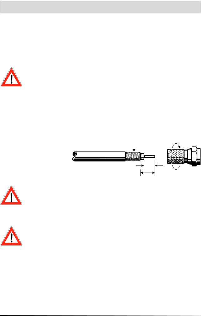
Connect the SAT-IF input on the UFD 170 to the satellite receiving system. Use a coaxial cable with a standard F connector
f the F connector is not yet fi tted on the cable, strip the insulation from the cable as shown in the following illustration and carefully twist the F connector onto the end of the cable until it is securely fi tted on the cable
braid bent back
7 mm
10 mm
When fi tting the connector, make sure that no wires from the braiding are touching the inner conductor - this could result in short circuit
The quality of the reception signal depends on the connection.
Receiving Requirements
Make sure that your own satellite antenna system is equipped with at least a universal LNB for digital reception in the high-band range.
Receiving System Presets
The presents for the control signals have been made for standard reception systems, i.e. 14/18 V for polarity reversal and 22 kHz switching signal for low/high band changeover on multi-feed reception systems.
8

Connection and Setup
TV Connection
Connect the UFD 170 (TV Scart socket) and the TV set with a Scart cable. If your TV has a stereo feature, you can receive the sound in stereo via the Scart connection.
Audio Connection
f you want to play the sound on your hi-fi system, connect the audio cinch sockets to the input sockets on the hi-fi system with an appropriate cable
Dolby Connection
The Dolby Digital data fl ow output (AC 3) is intended for connection to a Dolby Digital system
IR Receiver
Connect the infrared receiver to the “IR REMOTE IN” socket and position it such that it has a visual connection to the remote control. The
UFD 170 can only be operated by remote control
Inserting Batteries in the Remote Control
Remove the cover on the rear of the remote control. Insert the two batteries supplied into the remote control, ensuring correct polarity - this is shown on the base of the battery compartment.
Slide the cover back onto the housing until it clicks into place. Used batteries are special waste. Do not throw used batteries into your household waste; take them to a collection point for old batteries.
Electronic equipment is not household waste - in accordance with directive 2002/96/EC OF THE EUROPEAN PARLIAMENT AND THE COUNCIL of 27th January 2003 on used electrical and electronic equipment, it must be disposed of properly
At the end of its service life, take this unit for disposal at a relevant offi cial collection point.
9
Controls, Displays and Connections
This section contains a brief description of all controls, displays and connections.
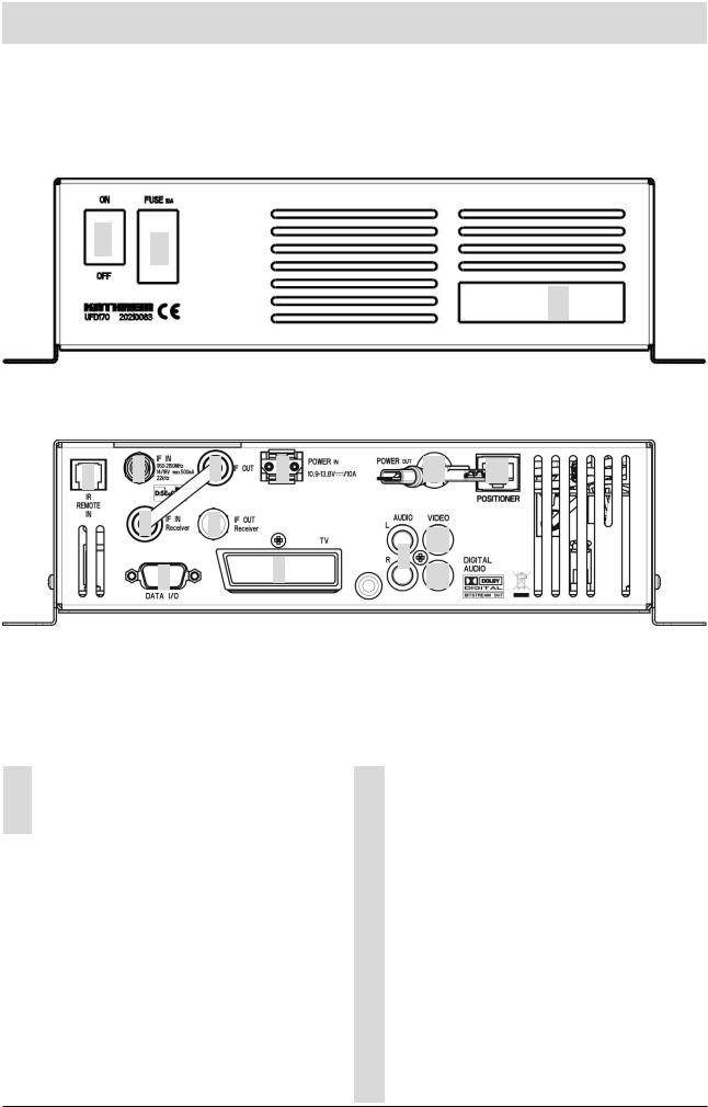
Front View
12
3
Rear View |
|
|
|
|
|
|
1 |
2 |
5 |
8 |
|
12 |
13 |
|
3 |
6 |
|
|
10 |
|
|
|
|
|
9 |
|
|
|
4 |
|
7 |
11 |
|
|
Front View |
|
Rear View |
1 |
Power switch (ON/OFF) |
1 |
Connection for separate infrared receiver |
2 |
Fuse |
2 |
Turntable unit SAT-IF signal input |
3 |
2 Common Interface slots for 2 CA modules |
3 |
Receiver SAT-IF signal input(connected to “5”) |
|
|
4 |
RS 232 data interface |
|
|
|
|
|
|
5 |
Turntable unit SAT-IF signal loop |
|
|
|
output (connected to “3”) |
|
|
6 |
SAF-IF signal loop output for receiver |
|
|
|
|
|
|
7 |
Scart socket for TV connection |
|
|
|
|
|
|
8 |
Mains voltage supply |
|
|
|
|
|
|
9 |
Audio outputs, 2 cinch sockets, L+R channel |
|
|
|
|
|
|
10 |
Video output (composite colour) |
|
|
|
|
|
|
11 |
Dolby Digital data stream output (AC 3) |
|
|
|
|
|
|
12 |
Power supply for turntable |
|
|
|
|
|
|
13 |
Output for data connection to turntable |
|
|
|
|
10
Controls, Displays and Connections
Remote Control Function Keys
The key symbols presented here can also be found in the description of the operating steps.
1

Controls, Displays and Connections
Important information on the remote control
You can only operate the UFD 170 using the remote control (RC 400) supplied. Without the remote control, it is not possible to set up or control the receiver and the turntable. Therefore, you should always take good care of your remote control and make sure you have spare batteries for it.
Remote control instruction sets
The remote control has two instruction sets. This alllows you to operate two receivers independently of one another in the same room.
Note |
This does not work in conjunction with a twin receiver! |
To use this feature, program the fi rst receiver to instruction set 1 and the second to instruction set 2
First turn on receiver 1 and then receiver 2 using the power switch
Hold down the key
Enter “901” using the number keys.
To transfer the code, switch receiver 1 to standby with and then turn the unit off with the power switch
Start up receiver 2 again.
Hold down the key
Enter “902” using the number keys.
To transfer the code, switch receiver 2 to standby with and then turn it back on
Start up receiver 1 again.
Hold down the key
Enter “903” using the number keys.
For the fi rst two settings, the remote control must be pointed at the relevant receiver turned on
You can now use the key to change between the two instruction sets A and B (toggle function), and operate the two receivers alternately
As supplied, instruction set 1 is always activated by default.
f you are only operating one receiver, and the active instruction set is accidentally changed so that you can no longer operate the receiver, the remote control can be switched back to instruction set 1 with no problems. This procedure is described above
12
Operating Instructions
Menu Concept
Note
The bar at the lower edge of the screen provides information on each menu option
The structure of the menu concept is based on logical operating sequences. In TV mode, the currently selected programme always appears in the upper right-hand corner of the screen (in radio mode, a black background is shown).
The selected menus, sub-menus and options, as well as the parameters to be set are all highlighted in colour. The menus are self-explanatory to a great extent
For a rough overview of the structure of the main menu and the subsequent sub-menus, you can refer to the Menu Structure section of this manual.
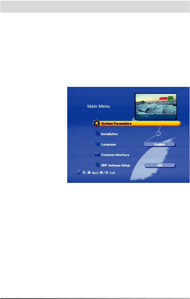
The main menu is opened |
by pressing and the |
sub-menus are selected using the |
keys |
The sub-menus are accessed by pressing The options in the sub-
keys
The settings in those options are made using either the keys or the number keys. The main menu, sub-menus and the individual
options are exitted using or
Language Selection
The language for the on-screen display is set as follows:
(Select menu language) - e.g. English - The languages available are German, English, Italian, French, Dutch, Portuguese, Spanish and Turkish
13
Operating Instructions
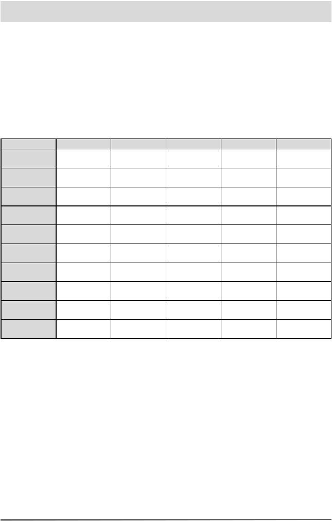
Alphanumeric Assignment of Remote Control Number Keys
You use the number keys to enter programme and satellite names. The numbers and letters appear in the name fi elds of the corresponding menus. Place the cursor in the name fi eld. The fi rst character is automatically given a dark background. You can now use the the number keys to enter letters by pressing the relevant key several times
For example, the “2” key is also used for A, B and C (see table below).
Key |
1 x |
2 x |
3 x |
4 x |
5 x |
|
|
|
? |
|
2 |
A |
B |
C |
2 |
3 |
D |
E |
F |
3 |
4 |
G |
H |
|
4 |
5 |
J |
K |
L |
5 |
6 |
M |
N |
O |
6 |
7 |
P |
Q |
R |
S |
8 |
T |
U |
V |
8 |
9 |
W |
X |
Y |
Z |
0 |
|
0 |
|
0 |
14

Menu Structure
Note
The “Language” menu option does not have any sub-menus. The langua-
ge is selected using the keys
15
Initial Setup
Important Information
Before setting up the system, make sure that it has been mounted, installed and connected properly, as described in the installation manual and the safety instructions.
Getting Started
Connect the unit to the power supply. Turn on the receiver using the power switch on the front. The unit is then in standby mode.
Turn on the receiver with the key on the remote control
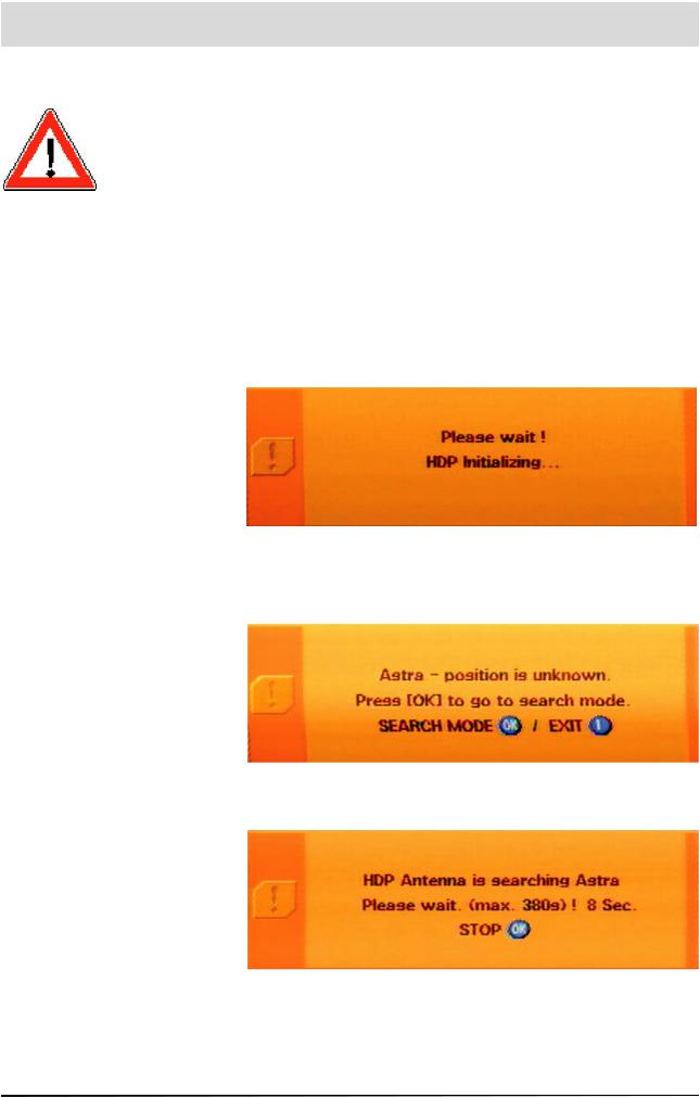
Your UFD 170 welcomes you. The following OSD then appears
The turntable then searches for the factory-preset programme. n this case, this is “Das Erste” on the ASTRA satellite. The following message then appears
Press the key to start the search
16
Initial Setup
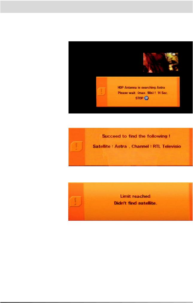
As soon as the turntable has found the correct satellite, the automatic fi ne-tuning is carried out. The search lasts a maximum of 90 seconds (if the signal level is suffi cient, the satellite position is immediately saved by the turntable). The screen may “freeze” during the fi ne tuning - this is determined by the system
f the turntable fi nds the desired satellite and the associated programme, the following message appears:
f the turntable is unable to fi nd the desired satellite and the associated programme, the following message appears:
ress and start satellite search with a different programme of the same satellite and check whether there are any obstructions to the antenna‘s reception.
After a successful search, you can select the factory-preset TV and
radio programmes using the |
keys. To change from TV pro- |
grammes to radio programmes, press Press to return to the
TV programmes
For details of how to save additional TV and radio programmes, refer to the “TV/Radio Programme Lists” section
When you turn on, the last reception status set is always activated. Check the time for summer or winter time (see Local
17
Initial Setup
This message appears when
“HDP mode” is deactivated
Press to switch to the main
menu, and then use the
keys to call up the “HDPAntenna Se-
tup” sub-menu. Use the keys to change the selection to “On”. Pres-
sing the keys takes you back to the normal TV screen
Time/Timer section).
f the message “Poor or no signal” appears on the screen as well as the display for the last programme received, check the installation of the system and/or the receiver settings. If this only affects individua programme slots, there may be an interrupted signal from the broadcaster or a fault in the reception system
First of all, check the connection confi guration and whether the default receiver settings are correct for your system. In case of doubt, consult a specialist engineer
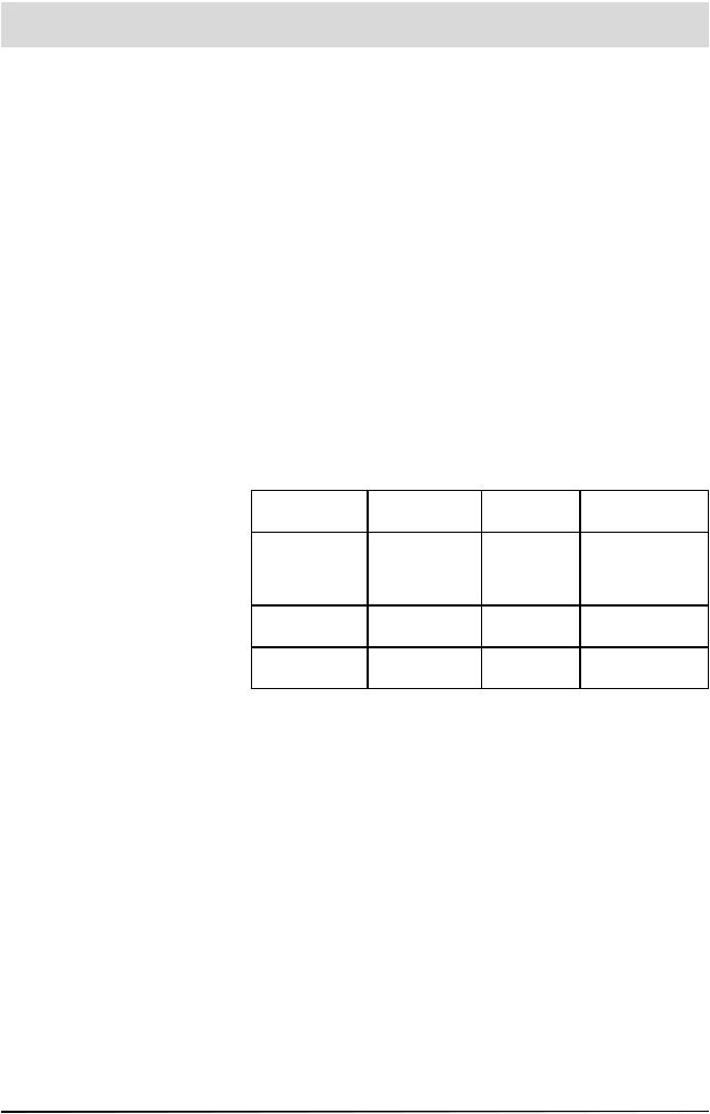
Receiver Factory Satellite Setting
Your receiver is factory-set up for the satellites listed in the following table. You do not normally need to make any additional settings.
ASTRA |
HOTBIRD |
EUTELSAT |
EUTELSAT |
|
19° East |
10° East |
16° East |
||
|
||||
TürkSat |
Telecom |
Telecom |
ASTRA 28.2° |
|
42° East |
5° East |
East (EURO- |
||
8° East |
||||
(EURASIA) |
(AtlanticBird 3) |
BIRD 28.5°) |
||
|
||||
Telestar12 |
Hisparsat |
EUTELSAT |
Amos 4° West |
|
15° West |
30° West |
7° East |
||
|
||||
Thor 1° West |
Sirius 5° East |
Arabsat |
|
|
(Intelsat 707) |
26° East |
|
||
|
|
18
On Screen Display (OSD)
General
Help Function
The bar at the lower edge of the screen provides information about each menu option
The receiver functions are controlled by a microprocessor and comprehensive software. The explanations below are intended to help you understand all the processes, and to enable you to locate errors
You can fi nd a detailed description of the individual menu functions in the relevant sections of this operating manual.
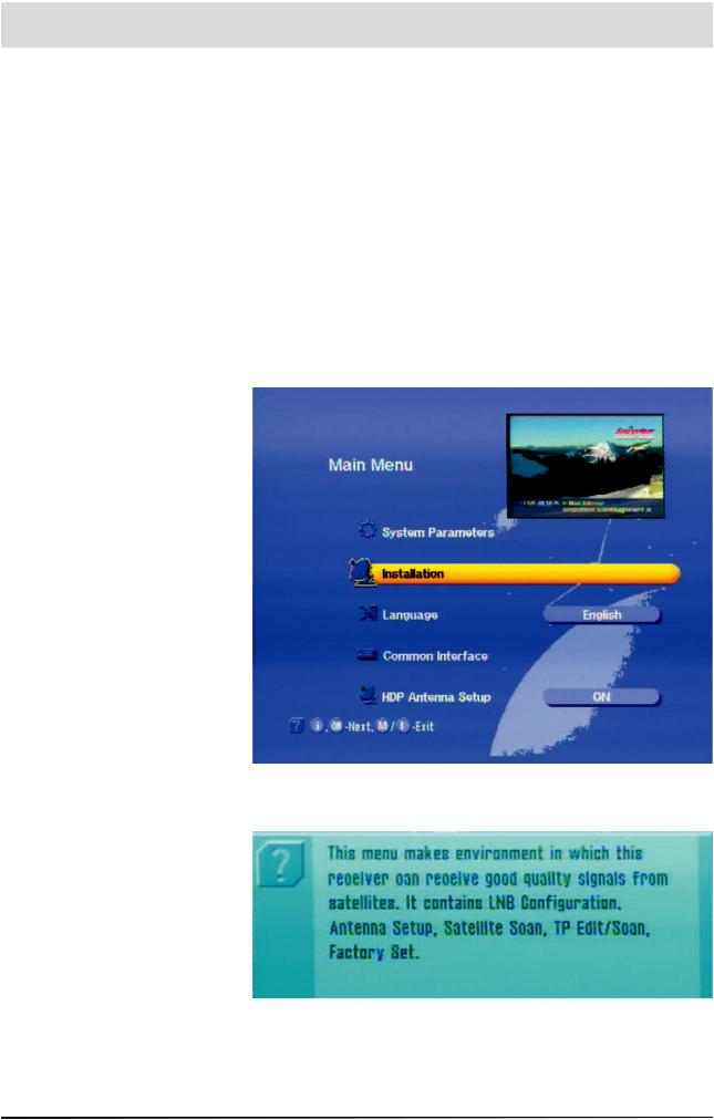
You can call up help for each menu or menu function. This help function provides you with a brief description of the most important functions of the selected menu option. For example, call up the main menu by
You can now view the help display for the “Installation” option by pressing
You can now view the help display for the “Installation” option by pressing
You can use the or keys to exit the help display and return to
the main menu. Pressing the key again takes you back to the original programme you were receiving
19
On Screen Display (OSD)
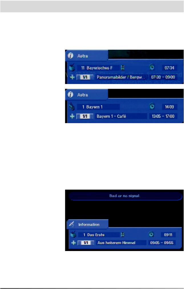
TV / Radio Channel Message
The channel message is displayed for a few seconds each time you
change the programme, or constantly if you press The “i ” indicates that a channel is being received even if no picture can be seen (e.g. in radio mode).
Channel
essag
TV
Channel
essag
Radio
The TV symbol indicates a TV channel - adjacent to it is the selected programme, whether video text can be received and the current time. The “+” in the third line stands for the programme selection from the overall list (when selecting from favourites list, an apple symbol appears instead of the “+”). This is followed by the programme title and the start and end times of the current programme, if this data is broadcast by the programme provider
The message for the set radio channel has the same layout. A radio unit symbol in the top left-hand corner indicates that it is a radio channel. Broadcast times and text are only shown if these are transmitted by the radio broadcaster
Error Message
“Weak or no signal” indicates that an error has occurred in the receiving system or in the receiver settings, or that the transponder is not sending. The channel message then shows a satellite antenna instead
of the “i”. Check the SAT-IF connection and the LNB confi guration. The list of service settings at the end of this manual can be used to help you do this
20
Video Text
This symbol in the programme display shows you whether video text is broadcast for the selected programme.
When you press the key, the receiver processes the broadcast video text - including for encrypted signals - for your TV set. The following display appears for a short time:
During a search, the programme page you are searching for (here P100) is shown in the top left-hand corner and the current time is shown in the right-hand corner
After completion of the search, the video text broadcast by the relevant programme provider appears
The individual pages can then be opened using the number keys.
During the search, a white star fl ashes in the top left-hand corner of the
creen
Press to exit the video text
2

Programme Selection
|
This section explains how to select television and radio programmes on |
|
|
your UFD 170 |
|
|
The description of the functions assumes that the UFD 170 has been |
|
|
connected and turned on properly |
|
Selecting a TV or Radio Programme |
|
|
Note |
Programme selection works in exactly the same way in TV and radio |
|
|
mode. We will therefore only explain how to select TV programmes |
|
|
here. The procedure for selecting a radio programme is identical to that |
|
|
described for the TV programmes |
|
Reception Status |
To select additional programmes in ascending or descending order |
|
|
||
|
in the programme memory, simply press the |
keys after |
|
turning on the UFD 170 |
|
After each change of programme, an on-screen display shows you the selected programme, the time, the programme start and end times and the programme title in an information bar (if this data is broadcast by the programme provider).
You can permantly show or hide this information bar by pressing the
key repeatedly
For encrypted programmes, you will see the following message:
You can only receive these programmes with the UFD 170 in conjunction with a CA module and the appropriate pay TV card (Smartcard)
22
Programme Selection
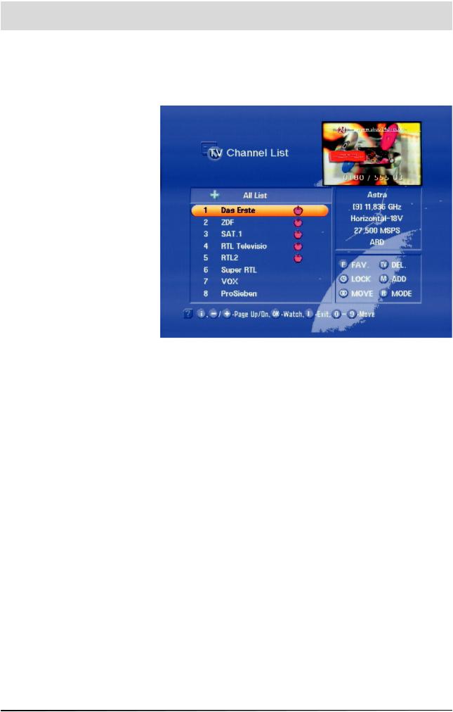
TV / Radio Channel List
An alternative method of selecting a different programme is to press the key, which opens the channel list
At the top left is a “+” for the complete list. In the column below it, you will see details of the channel name, the channel number and whether the programme is a favourite, locked or encrypted.
n the upper right-hand column you fi nd details of the satellites received, the transponder and its frequency, its polarisation and the symbol rate.
n the lower right-hand column, you will fi nd the “Programme / Channel Settings” menu
The factory settings for programmes and channels can be changed here. Pressing the
(Favourite) saves the channel shown as a favourite channel
(Lock) locks the channel shown
(Delete) deletes the channel shown
(Add) adds a new channel
(Move) moves the channel to a different position
(Mode) selects the mode for the channel list
The keys skip to the next programme, whereas the
keys skip to the next page. A selection is confi rmed with
You can also select a programme by entering a number.
Pressing , you exit the channel list, and return you to the previously selected programme
23
Programme Selection
Selecting TV/Radio Programmes by Number
|
You can select a different programme while a programme is |
|
being shown. To enter the programme number, use the number |
|
keys to |
Example: |
You want to select the programme “DSF” at programme number 15 |
|
(programme number assignment is an example). To do this, enter the |
|
numbers and The receiver waiting time for entry of the next |
|
digit is around three seconds |
|
The procedure for all other programmes - including those with |
|
three-digit programme numbers - is exactly the same |
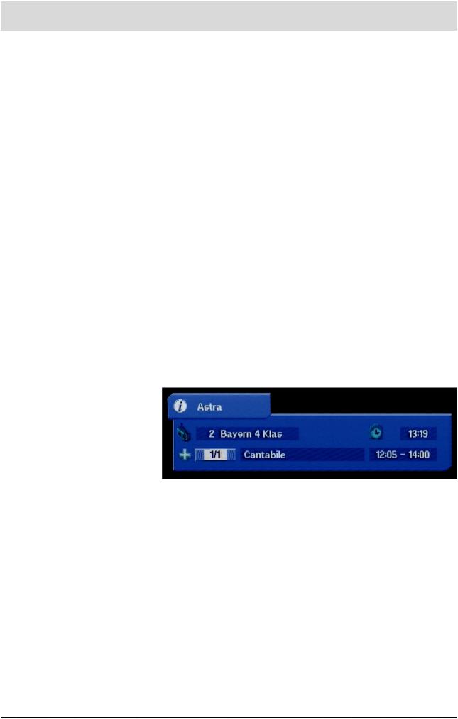
Switching from a TV Programme to a Radio Programme
You can switch from TV mode to radio mode. To do this, press on your remote control. The receiver then switches to the last radio programme selected
You can use the or key to return to TV mode
When switching to radio mode, just as in TV mode you will see a display for the programme received
n radio mode, the screen goes dark after a few seconds. However, you can permanently show the channel message by pressing
or hide it again by pressing the key again
24
Loading...