


KC..., KCT...
COOKING HOB VITROCERAMIC
KOCHFELD GLASKERAMIK
ВСТРАИВАЕМАЯ ВАРОЧНАЯ ПОВЕРХНОСТЬ СТЕКЛОКЕРАМИКА
3 5 |
5 |
|
EN USER
DE
RU ИНСТРУКЦИЯ ПО ОБСЛУЖИВАНИЮ И ЭКСПЛУАТАЦИИ

EN
DEAR CUSTOMERS,
thank you for purchasing this Kaiser product.
We are convinced that you have made a right choice. This product which satisfies the high quality demands and corresponds to world comprehensive standards realizes your cookeries, and his modern appearance which has been developed by the best European designers will decorate your kitchen splendidly.
We ask you to read the operating instructions before usage thoroughly. The consideration of recommendations protects you from possible inconveniences which can appear as a result of the wrong use of the cooking hobs, and allows you to reduce the consumption of electrical energy. If the use corresponds to the present operating instructions, the cooking hob will bring you a lot of pleasure for a long time.
Our cooking hobs correspond to the main demands of the security, hygiene and environment protection, according to the directives of the EU which is confirmed with certificates DIN ISO 9001, ISO 1400, according to the norms counting within the frames of the EU, they also correspond to the Gosstandart of Russia, standards of the CIS, which is confirmed with the corresponding certificates.
With the thoughts of a constant improvement of the quality of our cooking hobs the changes in design and equipment which lead only to positive changes of the technical qualities are reserved by the manufacturer.
We wish you an effective use of our cooking hob.
Yours faithfully
OLAN-Haushaltsgeräte
Berlin Germany
We Inform you that our devices which are the object of the present operating instructions are precertain exclusively for the domestic use.
2

DE |
|
|
|
|
RU |
|
|
|
|
|
||
LIEBE KUNDIN, LIEBER KUNDE, |
|
|
, |
|
|
|||||||
wir danken Ihnen für den Erwerb unserer Technik. |
. |
|||||||||||
Wir sind überzeug, dass Sie eine richtige Wahl getroffen |
, |
. |
||||||||||
haben. Dieses Produkt, das die hohen Forderungen zur |
, |
|||||||||||
Qualität befriedigt und weltumfassenden Standards |
|
, |
||||||||||
entspricht, verwirklicht Ihre Kochkünste, und sein |
|
|
|
|
|
|
|
|||||
modernes Aussehen, das von besten europäischen |
, , |
|||||||||||
Designer entwickelt worden ist, wird Ihre Küche |
|
|
|
|
|
|
||||||
prächtig schmücken. |
, . |
|||||||||||
Wir bitten Sie die Bedienungsanleitung vor der Nutzung |
! |
" |
||||||||||
aufmerksam zu lesen. Die Beachtung von Empfehlungen |
# |
$" |
|
|
|
|
||||||
schützt Sie von eventuellen Unannehmlichkeiten, die als |
. % |
|
# |
|
|
|||||||
Folge der falschen Nutzung des Kochfeldes auftreten |
" |
|
|
|
|
# |
||||||
können, und ermöglicht Ihnen den Verbrauch von |
|
|
|
$" |
||||||||
Elektroenergie zu reduzieren. Das Kochfeld bringt |
, # |
|||||||||||
Ihnen viel Vergnügen auf lange Zeit, wenn der |
|
|
$ $ . |
|
& |
|||||||
Gebrauch der vorliegenden Bedienungsanleitung |
$" |
|
|
|
|
|||||||
entsprechen wird. |
|
|
" |
, |
|
|||||||
|
|
|||||||||||
|
. |
|
|
|
|
|
|
|
|
|
|
|
Unsere Kochfelder entsprechen den Hauptforderungen |
' |
|
|
|
|
|||||||
der Sicherheit, der Hygiene und des Umweltschutzes, |
|
|
|
|
|
|
||||||
laut den Direktiven der EU, was mit Zertifikaten DIN |
, |
|
|
|
|
# |
||||||
ISO 9001, ISO 1400, entsprechend den im Rahmen der |
, & % , |
|||||||||||
EU geltenden Normen, bestätigt ist, und genauso auch |
# ( |
DIN ISO 9001, |
||||||||||
den Anforderungen von Gosstandart in Russland und |
ISO 1400, |
|
, |
|||||||||
Standards anderer GUS Länder, was durch die |
|
|
|
|
|
& |
||||||
Identifikationszertifikate bestätigt ist. |
, a # |
|||||||||||
|
) * |
|
|
|||||||||
|
|
|
|
%'), |
|
|
# |
|||||
|
( |
. |
|
|
|
|
|
|||||
Mit den Gedanken der ständigen Verbesserung der |
% |
|
||||||||||
Qualität unserer Kochfelder sind Änderungen bei |
$" |
|||||||||||
Design und Einrichtung, die nur zu positiven |
|
|||||||||||
Veränderungen der technischen Eigenschaften führen, |
|
|
|
|
|
|
, |
|||||
vom Hersteller vorbehalten. |
|
|
|
|
# |
|
|
|||||
|
|
. |
||||||||||
Wir wünschen Ihnen die effektive Nutzung unseres |
+ $(( |
|||||||||||
Kochfeldes. |
( . |
|
|
|
|
|
|
|
|
|
|
|
Hochachtungsvoll |
-# |
|
|
|
|
|
|
|
|
|
||
OLAN-Haushaltsgeräte |
OLAN-Haushaltsgeräte |
Berlin Germany |
Berlin Germany |
Wir Informieren Sie, dass unsere Geräte, die der Gegenstand der vorliegenden Bedienungsanleitung sind, sind ausschließlich für den häuslichen Gebrauch vorbestimmt.
/ ( , ,/ " ,.
3
EN
CONTENTS
INSTALLATION INSTRUCTIONS |
6 |
Electrical connection |
6 |
Installation of the hobs |
8 |
BRIEF DESCRIPTION |
10 |
Location drawing |
10 |
Control panel |
14 |
EQUIPMENT |
16 |
Heating elements |
16 |
USAGE |
20 |
Cooking zones control - models KCT 69… |
20 |
Cooking zones control - models KCT 39… |
42 |
Cooking zones control - models KC 20..., |
|
KC 39..., KC 69... |
56 |
CARE AND ATTENDANCE |
58 |
ENVIROMENTAL COMPATIBILITY |
62 |
4
DE |
|
|
RU |
|
NHALTSVERZEICHNIS |
|
|
|
|
FÜR DEN INSTALLATEUR |
7 |
|
7 |
|
Stromanschluss |
7 |
|
7 |
|
Einbau des Kochfeldes |
9 |
|
9 |
|
KURZBESCHREIBUNG |
11 |
|
11 |
|
Gesamtansicht |
11 |
|
|
11 |
Bedienblende |
15 |
|
15 |
|
AUSSTATUNG |
17 |
|
|
17 |
Heizelemente |
17 |
|
|
17 |
BENUTZUNG |
21 |
|
21 |
|
Kochfeldersteuerung - Modelle KCT 69… |
21 |
|
|
|
|
|
- KCT 69… |
21 |
|
Kochfeldersteuerung - Modelle KCT 39… |
43 |
|
|
|
|
|
- KCT 39… |
43 |
|
Kochfeldersteuerung - Modelle KC 20..., |
|
|
|
|
KC 39..., KC 69... |
57 |
- KC 20..., KC 39..., KC 69... |
57 |
|
PFLEGE UND WARTUNG |
59 |
|
|
59 |
UMWELTVERTRÄGLICHKEIT |
63 |
|
63 |
|
5
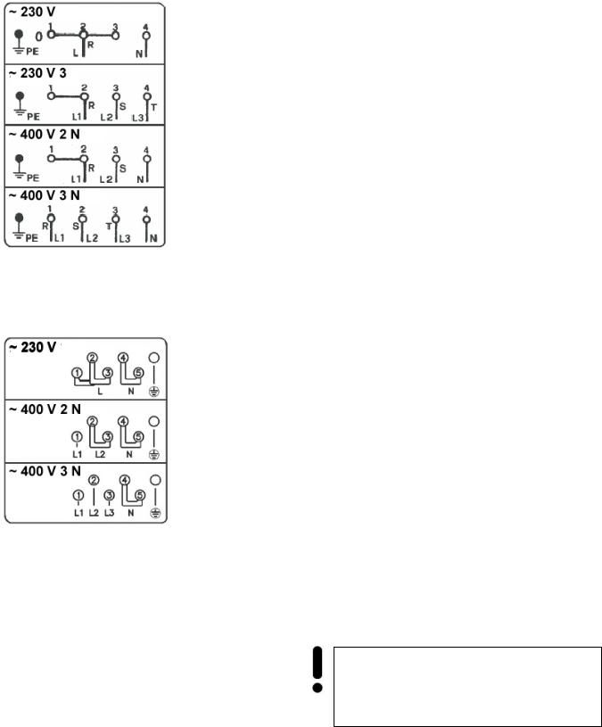
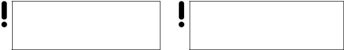
H05RR - F3x2.5
H05RR - F4x1.5
H05RR - F4x1.5
H05RR - F5x1.5
EN
NSTALLATION INSTRUCTIONS
ELECTRICAL CONNECTION
Before connecting the cooking hob to the mains power supply, make sure that:
the plant characteristics are such as to follow what is indicated on the matrix plate placed at the bottom of the working area,
the mains supply has an efficient ground connection complying with all applicable laws and regulations.
Correct grounding is a legal requirement. If the appliance is not pre-fitted with a power cable and/or plug, use only suitable cables and plugs capable of handling the power specified on the appliance's data plate and capable of resisting heat. The power cable should never reach a temperature 50°C above ambient temperature at any point along its length.
H05RR - F3x2.5
H05RR - F4x1.5
H05RR - F5x1.5
If the appliance is to be connected directly to mains terminals, fit a switch with minimum aperture of 3 mm between the contacts. Make sure that the switch is of sufficient capacity for the power specified on the appliance's data plate, and compliant with applicable regulations. The switch must not break the yellow-green earth wire. The socket or switch must be easily reachable with the cooking hob fully installed.
Attention! The manufacturer declines all responsibility for damage or injury if the above instructions and normal safety precautions are not respected
6
DE |
|
RU |
FÜR DEN INSTALLATEUR |
|
|
STROMANSCHLUSS |
|
|
Vor der Durchführung des Stromanschlusses muss |
. |
|
sichergestellt werden, dass: |
|
, , : |
die Eigenschaften des Stromnetzes mit den |
|
|
Werten auf dem unter der Kochfeld |
! , |
|
angebrachten |
Leistungsschild |
|
übereinstimmen, |
|
|
das Stromnetz gemäß den geltenden . " "
Bestimmungen und Rechtsvorschriften |
# . |
||||||||||
geerdet ist. |
|
|
|
|
|
|
|
|
|
|
|
Die Erdung ist eine notwendige Voraussetzung der |
$" |
|
|
|
|||||||
Nutzung des Gerätes. Falls das Kochfeld nicht mit |
|
% . |
& |
|
|||||||
Kabel und\ oder Netzstecker ausgestattet ist, muss |
|
|
|
|
|
/ |
|||||
geeignetes Material verwendet werden, das der auf |
, |
|
|
|
, |
||||||
dem Typenschild auf dem unter das Gerät |
# |
" |
|||||||||
angegebene |
Stromaufnahme |
und |
der |
! , |
|
||||||
Betriebstemperatur entspricht. Das Kabel darf an |
* % |
! |
. |
||||||||
keiner Stelle keinesfalls eine Temperatur von über |
+ |
! |
|
|
|||||||
50°C erreichen. |
|
|
|
50°;. |
|
|
|
|
|
||
Wenn ein direkter Netzanschluss gewünscht wird, |
|
|
|
. |
||||||||
muss ein allpoliger Schalter mit Kontaktöffnung von |
|
, |
" |
|
% |
|||||||
min. 3 mm vorgesehen werden, der erlaubt das |
" " ! |
|||||||||||
Gerät vom Netz zu trennen, der den technischen |
|
|
|
|
3 |
, |
|
" # |
||||
Daten der geltenden Vorschriften entsprechen muss |
|
|
|
|
|
, |
|
|
||||
(das gelb-grüne Erdungskabel darf nicht vom |
# |
|||||||||||
genannten Schalter unterbrochen werden). Der |
(! - " |
" " |
! |
|||||||||
Stecker bzw. der allpolige Schalter müssen bei |
). < |
|||||||||||
installiertem Gerät problemlos zugänglich sein. |
|
|
|
|
|
|
||||||
|
|
! |
||||||||||
|
. |
|
|
|
|
|
|
|
|
|
||
Achtung! Der Hersteller ist nicht haftbar, wenn bei der Installation des Gerätes alle obenangeführten Anweisungen nicht befolgt werden
"#$"%! =" |
|
|
||
|
|
, |
|
|
|
|
|
||
7
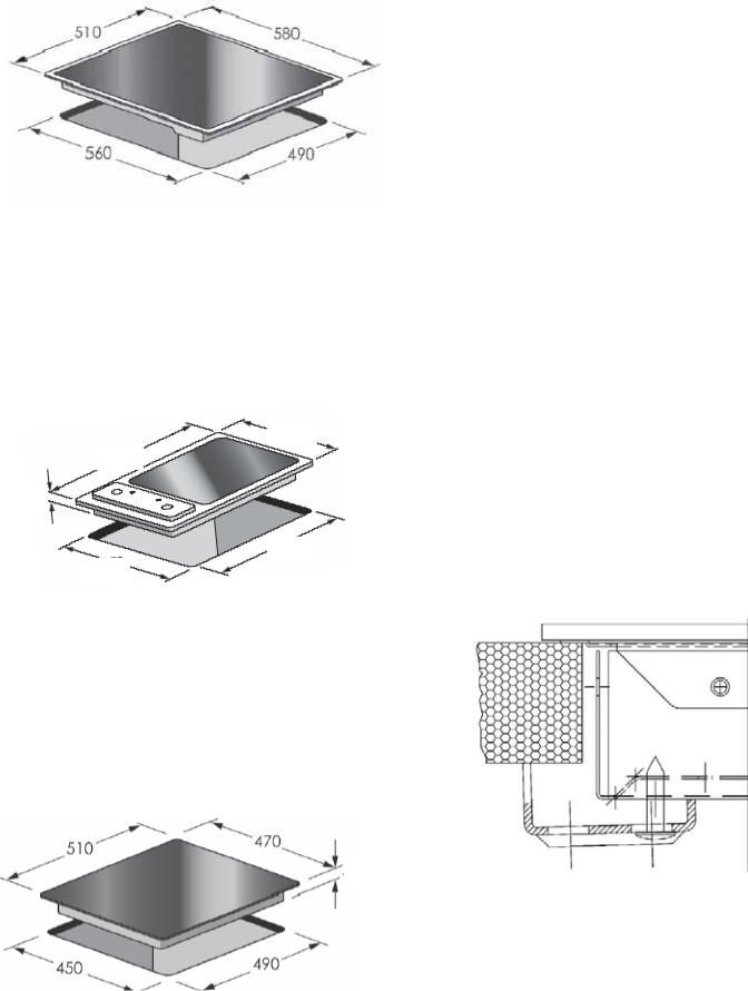
KC 69..., KCT 69...,
510 |
|
580 |
560 |
|
|
|
490 |
|
|
|
|
EN
INSTALLATION OF THE COOKING HOB
These Instructions are for the qualified technician, as a guide to the installation, adjustment and maintenance, according to the laws and standards in force.
Any of these operations must always be carried out when the appliance has been disconnected from the electric system.
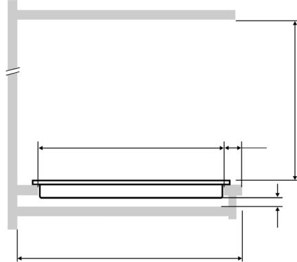
The appliance can be fitted into a working area as illustrated on the figure. Apply the seal supplied over the whole perimeter of the working area.
KCT 39...
288
510
45
494
270
KC 20..., KC 39...
510 |
|
470 |
40
450 |
|
490 |
8
DE |
RU |
EINBAU DES KOCHFELDES |
|
Die angegebenen Anweisungen sind an den zugelassenen Installateur als Richtlinie für die Installation, Regelung und Instandhaltung, gemäß den geltenden Gesetzen und Normen, gerichtet. Alle Arbeiten sollen nur bei abgeschaltet vom elektrischen Netz Apparat durchgeführt werden.
Der Apparat ist für den Einbau in eine Arbeitsplatte vorgesehen. Siehe Abbildung. Auf den ganzen Perimeter der Platte die mitgelieferte Dichtmasse verteilen.
; , !%# .
! .
, " ! % ..
min. 600
490 |
min. 50 |
min. 15
600
9
EN
BRIEF DESCRIPTION
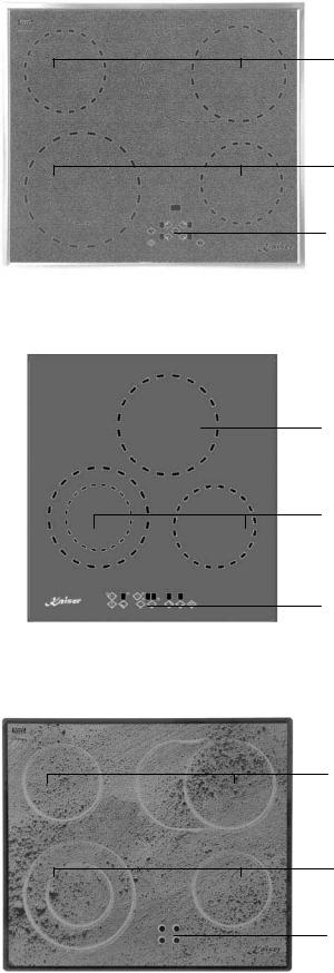
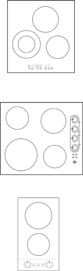
LOCATION DRAWING
KCT 69...
1 |
1. |
Cooking zone |
|
2. |
Touch control |
||
|
1
2
|
KCT 39... |
|
|
1. |
Cooking zone |
1 |
2. |
Touch control |
1
2
|
KC 69... ( Combi ) |
|
1 |
1. |
Cooking zone |
2. |
Residual heat indicator |
|
1
2
10
|
DE |
|
RU |
KURZBESCHREIBUNG |
|
||
GESAMTANSICHT |
& |
||
KCT 69... |
KCT 69... |
||
1. |
Kochzone |
1. |
|
2. |
Touch control |
2. |
; |
KCT 39... |
KCT 39... |
||
1. |
Kochzone |
1. |
|
3. |
Touch control |
2. |
; |
KC 69... ( Abhängig ) |
KC 69... ( $'"*"#+% ) |
||
1. |
Kochzone |
1. |
|
2. |
Restwärmeanzeige |
2. |
= |
11
EN
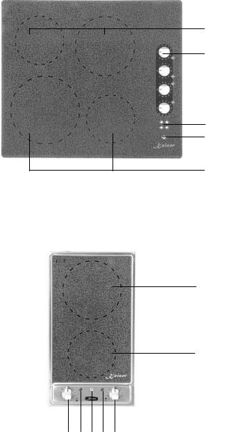
KC 69...
1
1. Cooking zone
32. Indicator Power ON/ Power OFF
3.Cooking zone knob
4.Residual heat indicator
4
2
1
1KC 20...
1.Cooking zone
2.Indicator Power ON/ Power OFF
3.Cooking zone knob
1 |
4. Residual heat indicator |
3 4 2 4 3
12
DE |
RU |
KC 69... |
KC 69... |
||
1. |
Kochzone |
1. |
|
2. |
Anzeige Ein / Aus |
2. |
= +>/ ?+> |
3. |
Drehregler des Kochzone |
3. |
@ |
4. |
Restwärmeanzeige |
4. |
= |
KC 20... |
KC 20... |
||
1. |
Kochzone |
1. |
|
2. |
Anzeige Ein / Aus |
2. |
= +>/ ?+> |
3. |
Drehregler des Kochzone |
3. |
@ |
4. |
Restwärmeanzeige |
4. |
= |
13
|
|
|
|
|
|
|
|
|
|
|
|
|
|
|
|
|
|
|
|
|
|
|
|
|
|
|
|
|
|
|
|
|
|
|
|
|
|
|
|
|
|
|
|
|
|
|
|
EN |
|
|
|
|
|
|
|
|
|
|
|
|
|
|
9 |
|
|
|
|
|
|
|
|
|
|
|
|
|
|
|
|
|
|
|
|
|
|
|
|
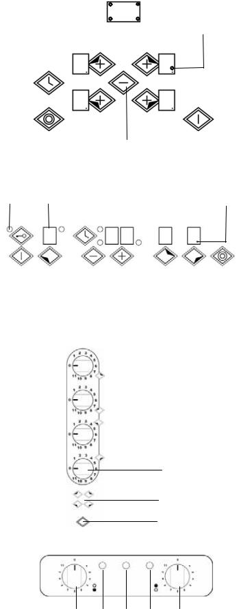
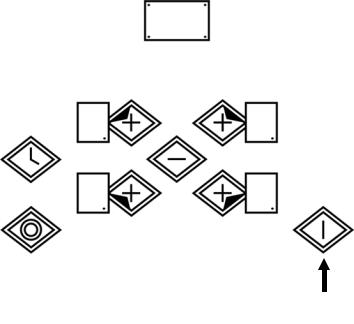
CONTROL PANEL |
|||||||||
|
|
|
|
|
|
|
|
|
|
|
|
|
|
|
|
|
|
|
|
|
|
|
|
|
|
|
|
|
|
|
|
|
|
|
|
|
|
|
|
|
|
|
|
|
|
|
KCT 69... |
|
|
|
|
|
|
|
|
|
|
|
|
|
|
|
|
|
|
|
|
|
|
|
|
|
|
|
|
|
|
6 |
|
|
|
|
|
|
|
|
|
|
|
|
|||||||
|
|
|
|
|
|
|
|
|
|
7 |
|
|
|
|
|
|
|
|
|
|
|
|
|
|
|
|
|
|
|
|
|
|
|
|
|
|
|
|
|
|||||||||
|
|
|
|
|
|
|
|
|
|
|
|
|
|
|
|
|
|
|
|
|
|
|
|
|
|
|
|
|
|
|
|
|
|
|
|
|
|
|
||||||||||
|
|
|
|
|
|
|
|
|
|
|
|
|
|
|
|
|
|
|
|
|
|
|
|
|
|
|
|
|
|
|
|
|
|
|
|
|
|
|
|
|
|
|
|
|
||||
|
|
|
|
|
|
|
|
|
|
|
|
|
|
|
|
|
|
|
|
|
|
|
|
|
|
|
|
|
|
|
|
|
|
|
|
|
8 |
|
|
|
|
1. |
Power ON/ Power OFF |
|||||
|
|
|
|
|
|
|
|
|
|
|
|
|
|
|
|
|
|
|
|
|
|
|
|
|
|
|
|
|
|
|
|
|
|
|
|
|
|
|
|
|||||||||
|
|
|
|
|
|
5 |
|
|
|
|
|
|
|
|
|
|
|
|
|
|
|
|
|
|
|
|
|
|
|
|
|
|
|
|
|
|
|
|
|
|
|
|
|
2. |
Cooking zone + |
|||
|
|
|
|
|
|
|
|
|
|
|
|
|
|
|
|
|
|
|
|
|
|
|
|
|
|
|
|
|
|
|
|
|
|
|
|
|
|
|
|
|
|
|
||||||
|
|
|
|
|
|
|
|
|
|
|
|
|
|
|
|
|
|
|
|
|
|
|
|
|
|
|
|
|
|
|
|
|
|
|
|
|
|
|
|
|
|
|
3. |
Cooking zone - |
||||
|
|
|
|
|
|
|
|
|
|
|
|
|
|
|
|
|
|
|
|
|
|
|
|
|
|
|
|
|
|
|
|
|
|
|
|
|
|
|
|
|
|
|
|
|
|
|
||
|
|
|
|
|
|
|
|
|
|
|
|
|
|
|
|
|
|
|
|
|
|
|
|
|
|
|
|
|
|
|
|
|
|
|
|
|
|
|
|
|
|
|
|
|
|
|
4. |
Dual circuit |
|
|
|
|
|
|
|
|
|
|
|
|
|
|
|
|
|
|
|
|
|
|
|
|
|
|
|
|
|
|
|
|
|
|
|
|
|
|
|
|
|
|
|
|
|
|
|
||
|
|
|
|
|
|
|
|
|
|
|
|
|
|
|
|
|
|
|
|
|
|
|
|
|
|
|
|
|
|
|
|
|
|
|
|
|
|
|
|
|
|
|
|
|
|
|
5. |
Timer |
|
|
|
|
|
|
|
|
|
|
|
|
|
|
|
|
|
|
|
|
|
|
|
|
|
|
|
|
|
|
|
|
|
|
|
|
|
|
|
|
|
|
|
|
|
|
|
6. |
Setting display |
|
|
|
|
|
|
|
|
|
|
|
|
|
|
|
|
|
|
|
|
|
|
|
|
|
|
|
|
|
|
|
|
|
|
|
|
|
|
|
|
|
|
|
|
|
|
|
7. |
Timer display |
|
|
|
|
|
|
|
|
|
|
|
|
|
|
|
|
|
|
|
|
|
|
|
|
|
|
|
|
|
|
|
|
|
|
|
|
|
|
|
|
|
|
|
|
|
|
|
8. |
Dual circuit LED |
|
|
|
|
|
|
|
|
|
|
|
|
|
|
|
|
|
|
|
|
|
|
|
|
|
|
|
|
|
|
|
|
|
|
|
|
|
|
|
|
|
|
|
|
|
|
|
9. |
Timer LED |
|
|
|
|
|
|
|
|
|
|
|
|
|
|
|
|
|
|
|
|
|
|
|
|
|
|
|
|
|
|
|
|
|
|
|
|
|
|
|
|
|
|
|
|
|
|
|
||
|
|
|
|
|
|
|
|
|
|
|
|
|
|
|
|
|
|
|
|
|
|
|
|
|
|
|
|
|
|
|
|
|
|
|
|
|
|
|
|
|
|
|
|
|
|
|
|
|
|
|
|
|
|
|
|
|
4 |
|
|
|
|
|
|
|
|
|
|
|
3 |
|
|
|
|
|
|
|
|
|
|
|
1 |
|
|
|
|
|
|
||||||||||
|
|
|
|
|
|
|
|
|
|
|
|
|
|
|
|
|
|
|
|
|
|
|
|
|
|
|
|
|
|
|
|
|
|
|
|
|
|
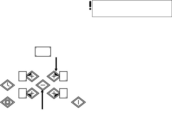
KCT 39... |
||||||||||
|
|
|
|
|
|
|
|
|
|
|
|
|
|
|
|
|
|
|
|
|
|
|
|
|
|
|
|
|
|
|
|
|
|
|
|
|
|
|
|
|
|
|
|
|
|
|
||
|
|
|
|
|
|
|
|
|
|
|
|
|
|
|
|
|
|
|
|
|
|
|
|
|
|
|
|
|
|
|
|
|
|
|
|
|
||||||||||||
11 |
8 |
|
|
3 |
9 |
|
|
|
6 |
|
|
|
7 |
|
|
|
3 |
|
|
|
3 |
|
|
12 |
1. |
Power ON/ Power OFF |
||||||||||||||||||||||
|
|
|
|
|
|
|
|
|
|
|
|
|
|
|
|
|
|
|
|
|
|
|
|
|
|
|
|
|
|
|
|
|
|
|
|
|
|
|
|
|
|
|
|
|
|
|
||
|
|
|
|
|
|
|
|
|
|
|
|
|
|
|
|
|
|
|
|
|
|
|
|
|
|
|
|
|
|
|
|
|
|
|
|
|
|
|
|
|
|
|
|
|
|
|
||
|
|
|
|
|
|
|
|
|
|
|
|
|
|
|
|
|
|
|
|
|
|
|
|
|
|
|
|
|
|
|
|
|
|
|
|
|
|
|
|
|
|
|
|
|
|
|
2. |
Cooking zone |
|
|
|
|
|
|
|
|
|
|
|
|
|
|
|
|
|
|
|
|
|
|
|
|
|
|
|
|
|
|
|
|
|
|
|
|
|
|
|
|
|
|
|
|
|
|
|
3. |
Power display |
|
|
|
|
|
|
|
|
|
|
|
|
|
|
|
|
|
|
|
|
|
|
|
|
|
|
|
|
|
|
|
|
|
|
|
|
|
|
|
|
|
|
|
|
|
|
|
4. |
Higher / Lower |
|
|
|
|
|
|
|
|
|
|
|
|
|
|
|
|
|
|
|
|
|
|
|
|
|
|
|
|
|
|
|
|
|
|
|
|
|
|
|
|
|
|
|
|
|
|
|
5. |
Dual circuit |
|
|
|
|
|
|
|
|
|
|
|
|
|
|
|
|
|
|
|
|
|
|
|
|
|
|
|
|
|
|
|
|
|
|
|
|
|
|
|
|
|
|
|
|
|
|
|
6. |
Timer |
|
|
|
|
|
|
|
|
|
|
|
|
|
|
|
|
|
|
|
|
|
|
|
|
|
|
|
|
|
|
|
|
|
|
|
|
|
|
|
|
|
|
|
|
|
|
|
||
|
|
|
|
|
|
|
|
|
|
|
|
|
|
|
|
|
|
|
|
|
|
|
|
|
|
|
|
|
|
|
|
|
|
|
|
|
|
|
|
|
|
|
|
|
|
|
7. |
Timer display |
|
|
|
|
|
|
|
|
|
|
|
|
|
|
|
|
|
|
|
|
|
|
|
|
|
|
|
|
|
|
|
|
|
|
|
|
|
|
|
|
|
|
|
|
|
|
|
8. |
Control lock (key) |
|
1 |
|
|
|
|
|
2 |
|
|
|
|
|
|
|
|
4 |
|
10 |
|
2 |
|
|
2 |
|
|
|
5 |
|
9. |
Dual circuit LED |
||||||||||||||||||
|
|
|
|
|
|
|
|
|
|
|
|
|
|
|
|
|
|
|
|
|
10. Timer LED |
|||||||||||||||||||||||||||
|
|
|
|
|
|
|
|
|
|
|
|
|
|
|
|
|
|
|
|
|
|
|
|
|
|
|
|
|
|
|
|
|
|
|
|
|
|
|
|
|
|
|
|
|
|
|
11. Lock LED |
|
|
|
|
|
|
|
|
|
|
|
|
|
|
|
|
|
|
|
|
|
|
|
|
|
|
|
|
|
|
|
|
|
|
|
|
|
|
|
|
|
|
|
|
|
|
|
|
||
|
|
|
|
|
|
|
|
|
|
|
|
|
|
|
|
|
|
|
|
|
|
|
|
|
|
|
|
|
|
|
|
|
|
|
|
|
|
|
|
|
|
|
|
|
|
|
||
|
|
|
|
|
|
|
|
|
|
|
|
|
|
|
|
|
|
|
|
|
|
|
|
|
|
|
|
|
|
|
|
|
|
|
|
|
|
|
|
|
|
|
|
|
|
|
||
|
|
|
|
|
|
|
|
|
|
|
|
|
|
|
|
|
|
|
|
|
|
|
|
|
|
|
|
|
|
|
|
|
|
|
|
|
|
|
|
|
|
|
|
|
|
|
12. |
Decimal point |
|
|
|
|
|
|
|
|
|
|
|
|
|
|
|
|
|
|
|
|
|
|
|
|
|
|
|
|
|
|
1 |
|
|
|
|
|
|
|
|
|
|
|
|
KC 69... |
|||||
|
|
|
|
|
|
|
|
|
|
|
|
|
|
|
|
|
|
|
|
|
|
|
|
|
|
|
|
|
|
|
|
|
|
|
|
|
|
|
|
|
|
|||||||
|
|
|
|
|
|
|
|
|
|
|
|
|
|
|
|
|
|
|
|
|
|
|
|
|
|
|
|
|
|
|
|
|
|
|
|
|
|
|
|
|
|
|
|
|
|
|
||
|
|
|
|
|
|
|
|
|
|
|
|
|
|
|
|
|
|
|
|
|
|
|
|
|
|
|
|
|
|
1 |
|
|
|
|
|
|
|
|
|
|
|
|
1. |
Cooking zone knob |
||||
|
|
|
|
|
|
|
|
|
|
|
|
|
|
|
|
|
|
|
|
|
|
|
|
|
|
|
|
|
|
|
|
|
|
|
|
|
|
|
|
|
|
|||||||
|
|
|
|
|
|
|
|
|
|
|
|
|
|
|
|
|
|
|
|
|
|
|
|
|
|
|
|
|
|
|
|
|
|
|
|
|
|
|
|
|
|
|
|
|
|
|
2. |
Residual heat indicators |
|
|
|
|
|
|
|
|
|
|
|
|
|
|
|
|
|
|
|
|
|
|
|
|
|
|
|
|
|
|
|
|
1 |
|
|
|
|
|
|
|
|
|
|
|
|
3. |
ON/OFF indicator light |
||
|
|
|
|
|
|
|
|
|
|
|
|
|
|
|
|
|
|
|
|
|
|
|
|
|
|
|
|
|
|
|
|
|
|
|
|
|
|
|
|
|
|
|
|
|
||||
|
|
|
|
|
|
|
|
|
|
|
|
|
|
|
|
|
|
|
|
|
|
|
|
|
|
|
|
|
|
|
|
|
|
|
|
|
|
|
|
|
|
|
|
|
||||
1
2
3
KC 20.29...
1 Cooking zone knob
2 Residual heat indicators
3 ON/OFF indicator light
1 |
2 |
3 |
2 |
1 |
|
|
14
|
DE |
|
|
RU |
|
|
|
|
|
BEDIENBLENDE |
|
|
|
|
|
||||
KCT 69... |
KCT 69... |
|
|
|
|
|
|
||
1. |
Ein / Aus Taste |
1. |
+ +>/ ?+> |
|
|
|
|
|
|
2. |
Kochzone + |
2. |
|
|
+ |
|
|
|
|
3. |
Kochzone - |
3. |
|
|
- |
|
|
|
|
4. |
Zweikreiskochzone: |
4. |
Q |
|
|
|
|
|
|
5. |
Timer |
5. |
U |
|
|
|
|
|
|
6. |
Anzeige eingestellter Wert |
6. |
Q |
|
|
|
|
||
7. |
Anzeige Timer |
7. |
Q |
|
|
|
|
|
|
8. |
LED Zweikreiskochzone: |
8. |
LED |
|
|
|
|||
9. |
Timer-LED |
9. |
LED |
|
|
|
|
|
|
KCT 39... |
KCT 39... |
|
|
|
|
|
|
||
1. |
Ein / Aus Taste |
1. |
+ +>/ ?+> |
|
|
|
|
|
|
2. |
Kochzone |
2. |
|
|
|
|
|
|
|
3. |
Display für Leistungsanzeige |
3. |
Q |
|
|
|
|
||
4. |
Minus / Plus |
4. |
X / |
|
|
|
|
|
|
5. |
Zweikreiskochzone: |
5. |
Q |
|
|
|
|
||
6. |
Timer |
6. |
U |
|
|
|
|
|
|
7. |
Display für Timer |
7. |
Q |
|
|
|
|
|
|
8. |
Inbetriebnahme-Kindersperre |
8. |
Y (+ ) |
|
|
|
|
|
|
9. |
LED zweiter Heizkreis |
9. |
LED |
|
|
|
|||
10. LED Zeitschaltuhr |
10. LED |
|
|
|
|
|
|
||
11. LED Sperre |
11. LED |
|
|
|
|
|
|||
12. Leuchtpunkt |
12. |
; |
|
|
|
|
|
||
KC 69... |
KC 69... |
|
|
|
|
|
|
||
1. |
Drehregler des Kochzone |
1. |
@ |
|
|
|
|||
2. |
Restwärmeanzeige |
2. |
= |
|
|||||
3. |
Kontrolleuchten Ein / Aus |
3. |
= / |
|
|||||
KC 20.29... |
KC 20.29... |
||
1 |
Drehregler des Kochzone |
1. |
@ |
2 |
Restwärmeanzeige |
2. |
= |
3 |
Kontrolleuchten Ein / Aus |
3. |
= / |
15
1
4
1
4
1
4
EN
EQUIPMENT
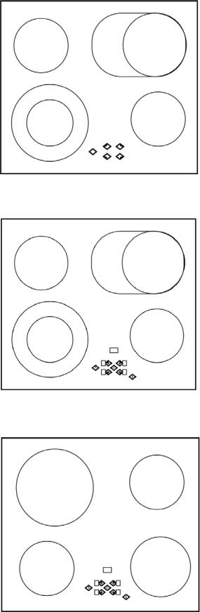
HEATING ELEMENTS
KC 692…
|
1. |
Cooking zone: |
Ø145 mm |
- 1,2 kW |
2 |
2. |
Dual circuit cooking zone: Ø170 mm |
- 1,4 kW, |
|
|
|
|
or 170x265 mm |
- 2,2 kW |
|
3. |
Cooking zone: |
Ø145 mm |
- 1,2 kW |
3 |
4. |
Dual circuit cooking zone: Ø120 mm |
- 0,7 kW |
|
|
|
or Ø210 mm |
- 2,1 kW |
|
|
KCT 691… |
|
|
|
1. Cooking zone: |
Ø145 mm |
- 1,2 kW |
2 |
2. Dual circuit cooking zone: Ø170 mm |
- 1,4 kW |
|
|
|
or 170x265 mm |
- 2,2 kW |
|
3. Cooking zone: |
Ø145 mm |
- 1,2 kW |
3 |
4. Dual circuit cooking zone: Ø120 mm |
- 0,7 kW |
|
|
or Ø210 mm |
- 2,1 kW |
|
|
KCT 690… |
|
|
|
|
1. |
Cooking zone: |
Ø210 mm |
- 2,1 kW |
2 |
2. |
Cooking zone: |
Ø145 mm |
- 1,2 kW |
|
3. |
Cooking zone: |
Ø180 mm |
- 1,7 kW |
|
4. |
Cooking zone: |
Ø145 mm |
- 1,2 kW |
3 |
|
|
|
|
16
|
DE |
|
|
RU |
|
|
AUSSTATUNG |
|
|
|
|
|
|
HEIZELEMENTE |
|
|
|
|
||
KC 692… |
|
|
KC 692… |
|
|
|
1. Kochzone: |
Ø145 mm |
- 1,2 kW |
1. : |
|
Ø145 mm |
- 1,2 kW |
2. Zweikreiskochzone: |
Ø170 mm |
- 1,4 kW |
2. Q |
: |
Ø170 mm |
- 1,4 kW |
oder 170x265 mm |
- 2,2 kW |
|
170x265 mm |
- 2,2 kW |
||
3. Kochzone: |
Ø145 mm |
- 1,2 kW |
3. : |
|
Ø145 mm |
- 1,2 kW |
4. Zweikreiskochzone: |
Ø120 mm |
- 0,7 kW, |
4. Q |
: |
Ø120 mm |
- 0,7 kW |
oder Ø210 mm |
- 2,1 kW |
|
Ø210 mm |
- 2,1 kW |
||
KCT 691… |
|
|
KCT 691… |
|
|
|
|
||
1. |
Kochzone: |
Ø145 mm |
- 1,2 kW |
1. |
: |
|
Ø145 mm |
- 1,2 kW |
|
2. |
Zweikreiskochzone |
Ø170 mm |
- 1,4 kW |
2. |
Q |
|
: |
Ø170 mm |
- 1,4 kW |
|
oder 170x265 mm |
- 2,2 kW |
|
|
|
170x265 mm |
- 2,2 kW |
||
3. |
Kochzone: |
Ø145 mm |
- 1,2 kW |
3. |
: |
|
Ø145 mm |
- 1,2 kW |
|
4. |
Zweikreiskochzone: |
Ø120 mm |
- 0,7 kW, |
4. |
Q |
|
: |
Ø120 mm |
- 0,7 kW |
|
oder Ø210 mm |
- 2,1 kW |
|
|
|
Ø210 mm |
- 2,1 kW |
||
KCT 690… |
|
|
KCT 690… |
|
|
|||
1. |
Kochzone: |
Ø210 mm |
- 2,1 kW |
1. |
|
: |
Ø210 mm |
- 2,1 kW |
2. |
Kochzone: |
Ø145 mm |
- 1,2 kW |
2. |
|
: |
Ø145 mm |
- 1,2 kW |
3. |
Kochzone: |
Ø180 mm |
- 1,7 kW |
3. |
|
: |
Ø180 mm |
- 1,7 kW |
4. |
Kochzone: |
Ø145 mm |
- 1,2 kW |
4. |
|
: |
Ø145 mm |
- 1,2 kW |
17
EN
KCT 39…
2
1 3
1 2
1. Dual circuit cooking zone: Ø120 mm |
- 0,7 kW |
||
|
|
or Ø180 mm - 1,7 kW |
|
2. |
Cooking zone: |
Ø180 mm |
- 1,7 kW |
3. |
Cooking zone: |
Ø145 mm |
- 1,2 kW |
KC 690…
|
|
1. |
Cooking zone: |
Ø145 mm |
- 1,2 kW |
|
|
2. |
Cooking zone: |
Ø180 mm |
- 1,7 kW |
|
|
3. |
Cooking zone: |
Ø145 mm |
- 1,2 kW |
4 |
3 |
4. |
Cooking zone: |
Ø210 mm |
- 2,1 kW |
KC 39…, KC 20
2
1. |
Cooking zone: |
Ø145 mm |
- 1,2 kW |
2. |
Cooking zone: |
Ø180 mm |
- 1,7 kW |
1
18
DE |
RU |
KCT 39… |
KCT 39… |
1. Zweikreiskochzone: |
Ø120 mm |
- 0,7 kW |
1. Q |
: Ø120 mm |
- 0,7 kW |
|||
|
oder Ø180 mm |
- 1,7 kW |
|
|
|
Ø180 mm |
- 1,7 kW |
|
2. |
Kochzone: |
Ø180 mm |
- 1,7 kW |
2. |
|
: |
Ø180 mm |
- 1,7 kW |
3. |
Kochzone: |
Ø145 mm |
- 1,2 kW |
3. |
|
: |
Ø145 mm |
- 1,2 kW |
KC 690… |
|
|
KC 690… |
|
|
|
|
||
1. |
Kochzone: |
Ø145 mm |
- 1,2 kW |
1. |
|
: |
Ø145 mm |
- 1,2 kW |
|
2. |
Kochzone: |
Ø180 mm |
- 1,7 kW |
2. |
|
: |
Ø180 mm |
- 1,7 kW |
|
3. |
Kochzone: |
Ø145 mm |
- 1,2 kW |
3. |
|
|
: |
Ø145 mm |
- 1,2 kW |
4. |
Kochzone: |
Ø210 mm |
- 2,1 kW |
4. |
|
|
: |
Ø210 mm |
- 2,1 kW |
KC 39…, KC 20 |
|
|
KC 39…, KC 20 |
|
|
||||
1. |
Kochzone: |
Ø145 mm |
- 1,2 kW |
1. |
|
|
: |
Ø145 mm |
- 1,2 kW |
2. |
Kochzone: |
Ø180 mm |
- 1,7 kW |
2. |
|
|
: |
Ø180 mm |
- 1,7 kW |
19
 2
2
1
20
EN
USAGE
COOKING ZONES CONTROL
MODELS KCT 69...
Switching the Touch Control ON/OFF
After mains voltage is applied the control initialises for approx. 1 second before it is ready for operation.
After a reset all displays and LEDs glow for approx. 1 second.
When this time is over all displays and LEDs extinguish and the control is in the stand-by mode.
By operating the ON/OFF key 1 the control can be turned into the ON-mode.
The cooking zone displays show a static “0“.
If a cooking zone is in the “hot“status, the display shows a static “H“ instead of “0“.
The bottom right dot 2 is blinking in 1 second intervals on all cooking zone displays to indicate that no cooking zone is selected at the moment.
After switching-ON the electronic control remains activated for 20 seconds.
If no cooking zone or timer selection follows within this period of time, the electronic control automatically switches back into the stand-by-mode. Should it recognize key activation other than that, the control remains in the stand- by-mode.
If the child safety feature is active when switching on, all cooking zones show “L“, (LOCKED). (also refer to Key lock).
If the cooking zones are in a “hot“ status, the display shows “L“ and “H“ in alternation.
The control can only be switched-ON if it identifies the ON/OFF key alone being operated.
When the Touch Control is ON it can be switchedOFF at any time by operating the ON/OFF key. This is also valid if the control has been locked (activated child safety feature).
The ON/OFF key has always priority in the switchOFF function.
When the control is ON it automatically switchesOFF after 20 seconds if no cooking zone or select key has been operated within this period of time.
If case of a cooking zone selection, the automatic switchOFF time is composed of 10 seconds deselection time for a cooking zone at setting“0“ and 10 seconds switch-OFF time.
DE |
|
|
|
|
|
|
|
RU |
|
|
|
|
|
||
BENUTZUNG |
|
|
|
|
|
|
|
||||||||
KOCHFELDERSTEUERUNG |
|
||||||||||||||
MODELLE KCT 69... |
- |
KCT 69… |
|
|
|
|
|
||||||||
EIN/AUS-Schalten der Touch Control |
:;<=% "%/ +:;<=% "% |
|
|
|
|
|
|
||||||||
Nach Anlegen der Netzspannung initialisiert sich die |
|
|
|
|
|
|
|
|
|
|
|||||
Steuerung für ca. 1 Sekunde bevor sie betriebsbereit |
% " 1 ., |
||||||||||||||
ist. |
! |
|
% . |
|
|
|
|||||||||
Nach einem Reset leuchten für 1 Sekunde alle |
|
|
|
|
c |
||||||||||
Anzeigen und LED´s. |
(LED) 1 . |
|
|
|
|
|
|||||||||
Nach Ablauf dieser Zeit werden alle Anzeigen und |
|
|
|
|
|
|
|
||||||||
LED´s wieder ausgeschaltet, und die Steuerung |
|
|
|
|
|
||||||||||
befindet sich im Stand-by Zustand. |
! ! Stand-by. |
|
|
||||||||||||
Die Steuerung kann nun durch Betätigen der |
" |
||||||||||||||
EIN/AUS-Taste 1 in den Ein-Zustand geschaltet |
+> / ?+> 1. |
|
|
|
|
|
|
|
|||||||
werden. |
|
|
|
|
|
|
|
|
|
|
|
|
|
|
|
Auf den Kochzonen-anzeigen erscheint statisch die |
|
"0". |
|||||||||||||
“0“. |
|
|
|
|
|
|
|
|
|
|
|
|
|
|
|
Sollte eine Kochzone den Status “Heiss“ besitzen, |
& - |
|
, |
|
" " |
||||||||||
wird an Stelle der “0“ ein statisches “H“ angezeigt. |
|
"0". |
|
|
|
|
|
|
|
|
|
|
|
||
Der Punkt rechts unten 2 blinkt auf allen Kochzonen- |
X # 1- . |
2, " |
|||||||||||||
anzeigen in einem 1-Sekunden-Takt zum Anzeigen, |
, " , |
||||||||||||||
dass momentan keine Kochzone selektiert ist. |
|
|
|
|
|
|
|
||||||||
Die Elektronik bleibt nach dem Ein-schalten für 20 |
|
. |
|
|
|
|
|
|
|
|
|||||
^ |
|
20 |
|||||||||||||
Sekunden aktiviert. |
|
|
. |
|
|
|
|
|
|
||||||
Findet innerhalb dieser Zeit keine Timeroder |
& |
|
|
|
|
||||||||||
Kochzonenanwahl statt, geht die Elektronik |
|
|
|
|
|
|
|
|
, |
||||||
selbständig wieder in den Stand-by Zustand. |
|
|
|
||||||||||||
Sollte eine beliebige weitere Taste ebenfalls als |
! ! . |
|
|
|
|
|
|
|
|
|
|||||
betätigt erkannt werden, bleibt die Steuerung im |
& " " |
|
|||||||||||||
Stand-by-Zustand. |
- , |
||||||||||||||
Sollte zum Zeitpunkt des Einschaltens die |
|
! |
! . |
|
|
|
|
|
|
|
|
||||
Kindersicherung noch aktiv sein, wird auf allen |
& |
||||||||||||||
Kochzonen ein “L“ wie LOCKED angezeigt (siehe |
, "L", |
||||||||||||||
auch Verriegelung). |
(locked - " ),( . Y ). |
||||||||||||||
Falls Kochzonen den Status “Heiss“ besitzen, wird |
& |
|
|
|
, |
|
|
|
|||||||
das “L“ im Wechsel mit dem “H“ angezeigt. |
"L" " " (hot / ). |
|
|
|
|||||||||||
Durch Betätigung der EIN/AUS-Tasten EIN-Zustand |
" +>/ ?+> |
||||||||||||||
der Steuerung läßt sich die Touch Control jederzeit |
|
|
, |
|
|
||||||||||
wieder aus-schalten. |
! . |
|
|||||||||||||
Dies gilt auch dann, wenn die Steuerung verriegelt |
^ |
|
|
! |
|
|
|||||||||
wurde (Kinder-sicherung aktiviert). |
. |
|
|
|
|
|
|
|
|
||||||
Die EIN / AUS-Taste hat in der Ausschalt-Funktion |
+ |
|
+>/ ?+> |
|
|
|
|
|
|||||||
immer Vorrang. |
. |
|
|
|
|
|
|
|
|
|
|
|
|||
Die Steuerung schaltet sich aus dem Ein-Zustand |
" |
||||||||||||||
nach 20 Sekunden. selbsttätig aus, wenn in dieser |
20 ., |
|
" |
|
|
||||||||||
Zeit keine Kochzone aktiviert oder eine Selekttatste |
|
|
- . |
|
|||||||||||
betätigt wurde. |
|
|
|
|
|
|
|
|
|
|
|
|
|
|
|
Die automatische Abschalt-zeit, im Falle einer |
|
|
, |
|
|
||||||||||
Kochzonenselektion, setzt sich zusammen aus, 10 |
! |
"0", |
|
|
" |
10 |
|
. |
|
||||||
Sekunden Deselektionszeit für eine Kochzone, die |
% , |
# |
|
" 10 . |
|||||||||||
auf Kochstufe “0“ steht und 10 Sekunden |
. |
|
|
|
|
|
|
|
|
|
|
|
|||
Ausschaltzeit. |
|
|
|
|
|
|
|
|
|
|
|
|
|
|
|
|
|
|
|
|
|
|
|
|
|
|
|
|
|
21 |
|
4
22
1
 2
2
 3
3
EN
Switching a cooking zone ON and OFF
If the control is ON the respective cooking zone can be selected by operating a cooking zone select key 1 (+)-key of the respective cooking zone.
Attention! When a dual circuit heating element is put into operation, all heating circuits are switchedON at the same time
There is a static dot indication 3 in the respective display 2. If the cooking zone is hot “0” is displayed instead of “H”.
On all other cooking zone displays the blinking dot extinguishes.
Then a setting will be chosen by a renewed operation of the cookingzoneselect (+)-key 1 or the (-)-key 4.
The cooking zone begins to heat up. In order to use the cooking-zone- selectkey as a (+)-key the control has to recognize that after the selection the cooking zone has been released for 0,3 seconds.
After selection of a cooking zone the setting can be increased by continously pressing the (+)-key 1, starting at step “1” it is increased by 1 step every 0,4 seconds.
When setting “9” is reached the setting will not be changed further (end stop).
If the selected cooking zone will be switched ON by means of the (-) key, the cooking zone starts at the maximum setting “9“(“reverse switching-ON”).
When the key is continuously operated, it decreases by 1 step every 0,4 seconds.
When setting “0” is reached, there will be no further setting changed (end stop).
Only a renewed operation of the (+) 1 or (-) 4 key changes the setting.
 Loading...