


Kaiser HGG 65501 KWWs, HGG 62501 S, HGG 64521KR, HGG 61532 R, HGG 60511 NW User Manual [ru]
...
HGG 6...
HGE 6...
GAS AND GAS-ELECTRIC COOKERS
GASUND GAS-ELEKTROHERDE
ГАЗОВЫЕ И ГАЗО-ЭЛЕКТРИЧЕСКИЕ ПЛИТЫ
EN USER MANUAL
DE GEBRAUCHSANWEISUNG
RU ИНСТРУКЦИЯ ПО ОБСЛУЖИВАНИЮ И ЭКСПЛУАТАЦИИ

EN
DEAR CUSTOMER,
thank you for purchasing this Kaiser product.
We are convinced that you have made the right choice. The appliance satisfies the high quality demands and corresponds to comprehensive international standards. Having been designed by the best European designers, the modern appearance of the cooker is sure to be a splendid interior decoration of your kitchen.
The cooker is intended to realize even your most complicated cookery projects.
Please read these instructions carefully before starting operation to be sure to obtain optimum performance. The following recommendations are aimed to protect you from possible inconveniences which can occur as a result of the wrong operation and, at the same time, reduce the consumption of electric energy. Proper operation and maintenance provide a longer service life of the unit and make cooking a pleasure.
The Kaiser cookers fulfill the main norms of safety, hygiene and environment protection in correspondence with the EU directives and are certified according to EU norms and standards (DIN ISO 9001, ISO 1400), standards of Russia (Gosstandart) and the CIS.
The company’s policy is aimed at constant improvement of product quality. Modifications made to the design and equipment result in exclusively positive changes in operating qualities of the appliances. The right for changes in the products is reserved by the manufacturer.
We wish you an effective use of the Kaiser product.
Yours faithfully,
OLAN-Haushaltsgeräte
Berlin Germany
The appliances under present operating instructions are designed for domestic and not industrial use.
2

DE RU
LIEBE KUNDIN, LIEBER KUNDE, |
, |
|
|||||||||||||||||||||||||||||||||||||||||||||||||||||||||||||||||||||||||
wir danken Ihnen für den Erwerb unserer Technik. |
. |
||||||||||||||||||||||||||||||||||||||||||||||||||||||||||||||||||||||||||
Wir sind überzeugt, dass Sie eine richtige Wahl |
, . |
||||||||||||||||||||||||||||||||||||||||||||||||||||||||||||||||||||||||||
getroffen haben. Dieses Produkt entspricht den hohen |
, |
||||||||||||||||||||||||||||||||||||||||||||||||||||||||||||||||||||||||||
Forderungen zur Qualität und den modernsten |
, |
||||||||||||||||||||||||||||||||||||||||||||||||||||||||||||||||||||||||||
internationalen Standards. Das Gerät wird Ihnen Ihre |
|
||||||||||||||||||||||||||||||||||||||||||||||||||||||||||||||||||||||||||
Kochprojekte ermöglichen, während sein modernes |
, |
, |
|||||||||||||||||||||||||||||||||||||||||||||||||||||||||||||||||||||||||
Aussehen, das von den besten europäischen Designern |
, |
||||||||||||||||||||||||||||||||||||||||||||||||||||||||||||||||||||||||||
entwickelt worden ist, zum Prachtstück Ihrer Küche |
. |
|
|
||||||||||||||||||||||||||||||||||||||||||||||||||||||||||||||||||||||||
wird. |
|
|
|
|
|
|
|
|
|
|
|
|
|
|
|
|
|
|
|
|
|
|
|
|
|
|
|
|
|
|
|
|
|
|
|
|
|
|
|
|
|
|
|
|
|||||||||||||||||||||||||||||||
Wir bitten Sie die Bedienungsanleitung vor der Nutzung |
|
|
|
! |
|||||||||||||||||||||||||||||||||||||||||||||||||||||||||||||||||||||||
aufmerksam zu lesen. Die Beachtung von Empfehlungen |
" # ! |
||||||||||||||||||||||||||||||||||||||||||||||||||||||||||||||||||||||||||
schützt Sie von eventuellen Unannehmlichkeiten, die als |
. $ " |
||||||||||||||||||||||||||||||||||||||||||||||||||||||||||||||||||||||||||
Folge der falschen Nutzung des Herds auftreten |
! " |
||||||||||||||||||||||||||||||||||||||||||||||||||||||||||||||||||||||||||
können, und ermöglicht Ihnen den Verbrauch von |
|
|
|
# ! |
|||||||||||||||||||||||||||||||||||||||||||||||||||||||||||||||||||||||
Elektroenergie zu reduzieren. Der Herd bringt Ihnen |
, " |
||||||||||||||||||||||||||||||||||||||||||||||||||||||||||||||||||||||||||
viel Vergnügen auf lange Zeit, wenn der Gebrauch der |
# #. % # ! |
||||||||||||||||||||||||||||||||||||||||||||||||||||||||||||||||||||||||||
vorliegenden Bedienungsanleitung entsprechen wird. |
!, |
||||||||||||||||||||||||||||||||||||||||||||||||||||||||||||||||||||||||||
|
|
|
|
|
|
|
|
|
|
|
|
|
|
|
|
|
|
|
|
|
|
|
|
|
|
|
|
|
|
|
|
. |
|
||||||||||||||||||||||||||||||||||||||||||
Unsere Herde entsprechen den Hauptforderungen der |
& |
||||||||||||||||||||||||||||||||||||||||||||||||||||||||||||||||||||||||||
Sicherheit, der Hygiene und des Umweltschutzes, laut |
, |
||||||||||||||||||||||||||||||||||||||||||||||||||||||||||||||||||||||||||
den Direktiven der EU, was mit Zertifikaten DIN ISO |
" |
|
, |
|
|
||||||||||||||||||||||||||||||||||||||||||||||||||||||||||||||||||||||
9001, ISO 1400, entsprechend den im Rahmen der EU |
% |
|
$ , |
|
|
" |
|||||||||||||||||||||||||||||||||||||||||||||||||||||||||||||||||||||
geltenden Normen, bestätigt ist, und genauso auch den |
' DIN ISO 9001, ISO 1400, |
||||||||||||||||||||||||||||||||||||||||||||||||||||||||||||||||||||||||||
Anforderungen von Gosstandart in Russland und |
|
|
|
|
|
, |
|||||||||||||||||||||||||||||||||||||||||||||||||||||||||||||||||||||
Standards anderer GUS Länder, was durch die |
|
|
|
|
% |
||||||||||||||||||||||||||||||||||||||||||||||||||||||||||||||||||||||
Identifikationszertifikate bestätigt ist. |
, a " |
||||||||||||||||||||||||||||||||||||||||||||||||||||||||||||||||||||||||||
|
|
|
|
|
|
|
|
|
|
|
|
|
|
|
|
|
|
|
|
|
|
|
|
|
|
|
|
|
|
|
|
( ) |
|||||||||||||||||||||||||||||||||||||||||||
|
|
|
|
|
|
|
|
|
|
|
|
|
|
|
|
|
|
|
|
|
|
|
|
|
|
|
|
|
|
|
|
$&(, " |
|||||||||||||||||||||||||||||||||||||||||||
|
|
|
|
|
|
|
|
|
|
|
|
|
|
|
|
|
|
|
|
|
|
|
|
|
|
|
|
|
|
|
|
' . |
|
|
|||||||||||||||||||||||||||||||||||||||||
Mit den Gedanken der ständigen Verbesserung der |
$ |
||||||||||||||||||||||||||||||||||||||||||||||||||||||||||||||||||||||||||
Qualität unserer Herde sind Änderungen bei Design |
# ! |
||||||||||||||||||||||||||||||||||||||||||||||||||||||||||||||||||||||||||
und Einrichtung, die nur zu positiven Veränderungen |
|
||||||||||||||||||||||||||||||||||||||||||||||||||||||||||||||||||||||||||
der technischen Eigenschaften führen, vom Hersteller |
|
|
|
|
|
, |
|
|
|||||||||||||||||||||||||||||||||||||||||||||||||||||||||||||||||||
vorbehalten. |
" |
||||||||||||||||||||||||||||||||||||||||||||||||||||||||||||||||||||||||||
|
|
|
|
|
|
|
|
|
|
|
|
|
|
|
|
|
|
|
|
|
|
|
|
|
|
|
|
|
|
|
|
. |
|
|
|
|
|
||||||||||||||||||||||||||||||||||||||
Wir wünschen Ihnen die effektive Nutzung unseres |
* #'' |
||||||||||||||||||||||||||||||||||||||||||||||||||||||||||||||||||||||||||
Produkts. |
'. |
|
|
|
|
|
|
|
|||||||||||||||||||||||||||||||||||||||||||||||||||||||||||||||||||
Hochachtungsvoll |
+ " |
|
|
|
|
|
|
||||||||||||||||||||||||||||||||||||||||||||||||||||||||||||||||||||
|
|
|
|
|
|
|
|
|
|
|
|
|
|
|
|
|
|
|
|
|
|
|
|
|
|
|
|
|
|
|
|
|
|
|
|
|
|
|
|
|
|
|
|
|
|
|
|
|
|
|
|
|
|
|
|
|
|
|
|
|
|
|
|
|
|
|
|
|
|
|
|
|
|||
OLAN-Haushaltsgeräte |
OLAN-Haushaltsgeräte |
|
|
|
|
||||||||||||||||||||||||||||||||||||||||||||||||||||||||||||||||||||||
Berlin Germany |
Berlin Germany |
|
|
|
|
|
|
||||||||||||||||||||||||||||||||||||||||||||||||||||||||||||||||||||
Wir Informieren Sie, dass unsere Geräte, die der Gegenstand der |
, ', , |
||||||||||||||||||||||||||||||||||||||||||||||||||||||||||||||||||||||||||
vorliegenden Bedienungsanleitung sind, sind ausschließlich für den |
, !, |
||||||||||||||||||||||||||||||||||||||||||||||||||||||||||||||||||||||||||
häuslichen Gebrauch vorbestimmt. |
. |
|
|
|
|
|
|||||||||||||||||||||||||||||||||||||||||||||||||||||||||||||||||||||
3
EN
CONTENTS
INSTALLATION INSTRUCTIONS |
6 |
Installation |
6 |
Connection |
8 |
Adjustment to different gas types |
12 |
Safety conditions |
14 |
BRIEF DESCRIPTION |
18 |
Location drawing |
18 |
Control panel |
20 |
EQUIPMENT |
22 |
Gas cooking zones control |
24 |
Gas oven control |
28 |
Multifunction electrical oven control |
30 |
Operation functions of the oven |
32 |
Oven |
40 |
Electronic sensor timer Touch control |
42 |
PRACTICAL ADVICE |
56 |
CLEANING AND SERVICING |
64 |
ENVIROMENTAL COMPATIBILITY |
74 |
4
DE RU
INHALTSVERZEICHNIS |
|
|
|
FÜR DEN INSTALLATEUR |
7 |
|
7 |
Aufstellen des Herdes |
7 |
|
7 |
Gasherd anschließen |
9 |
|
9 |
Anpassung an eine andere Gasart |
13 |
|
13 |
Sicherheitsbedingungen |
15 |
|
15 |
KURZBESCHREIBUNG |
19 |
|
19 |
Gesamtansicht |
19 |
|
19 |
Bedienblende |
21 |
|
21 |
AUSSTATUNG |
23 |
|
23 |
|
|
|
|
Gebrauch vom Gaskochfeld |
25 |
|
25 |
|
|
|
|
Steuerung von Gasbackofen |
29 |
|
29 |
|
|
|
|
Steuerung von Multifunktionselektrobackofen |
31 |
! |
31 |
Betriebsfunktion des Backofens |
33 |
" |
33 |
Gebrauch vom Backofen |
41 |
|
41 |
Elektronische Zeitschaltuhr Touch control |
|
# ! $ |
|
mit Sensorbedienung |
43 |
Touch control |
43 |
PRAKTISCHE EMPFEHLUNGEN |
57 |
|
57 |
PFLEGE UND WARTUNG |
65 |
|
65 |
UMWELTVERTRÄGLICHKEIT |
75 |
|
75 |
5

EN
INSTALLATION INSTRUCTIONS
INSTALLATION
Unhampered access to all control units as well as duly ventilation of the kitchen are primary installation requirements.
Before using your new appliance, make sure to fit it properly. By fixing the adjustable feet in a proper position, you can keep the upper surface strictly horizontally and, thus, avoid backlash. For this purpose, take out the drawer at the bottom.
The cooker is intended to be build up into kitchen furniture, however, only up to the height of the working plate, i.e. fixing up higher than 850 mm from the floor level is unreasonable.
All materials used for furniture panels should be heat resistant at the temperature 100°C minimum. Breach of this regulation can result in distortion or ungluing of panel coverings. To avoid heat distortion of the furniture panels, ensure that the space between the contact surfaces is not less than 2 cm.
Please mount the fume extractor hood at about 600-700 mm above the cooking surface (see installation instructions for your fume extractor hood).
3,5 kWt gas cookers are provided with a connecting cable (cross-section – 3 x 1,5 mm2, length – approx. 1,5 m) and a plug equipped with a safety stud.
Make sure that the AC outlet is isolated and not placed above the cooker.
After the cooker has been installed, check up if the electrical outlet is easy to access.
6
|
|
|
DE |
|
|
|
|
|
RU |
|
|
|
|
FÜR DEN INSTALLATEUR |
|
|
|
|
|
||||||||
AUFSTELLEN DES HERDES |
|
|
|
|
|
|
|||||||
Der Küchenraum muss eine funktionstüchtige |
% $ & |
||||||||||||
Ventilation haben und der Herd ist so aufzustellen, |
, & |
||||||||||||
dass der Benutzer einen freien Zutritt zu allen |
, |
||||||||||||
Bedienelementen hat. |
|
|
|
|
! |
||||||||
|
|
|
|
|
|
|
. |
|
|
|
|
|
|
Vor dem Benutzen stellen Sie den Herd richtig auf, |
' a a o |
||||||||||||
durch Drehen von Stützfüßen erreichen Sie die |
, pa$e e o p o&e |
||||||||||||
horizontale Lage der Oberfläche des Herdes. Dafür |
& . |
||||||||||||
nehmen Sie den unteren Kasten heraus. |
|
' ! & $ . |
|
|
|
||||||||
Der Herd darf in die Reihe von Möbel nur bis zu |
& |
||||||||||||
der Höhe der Arbeitsoberfläche der Möbel, d.h. |
, |
||||||||||||
850 mm vom Fußboden eingebaut werden. Einbau |
. . 850 . ( ! |
||||||||||||
über diese Höhe ist unzweckmäßig. Die |
. |
|
|
|
|||||||||
Küchenmöbel soll Verkleidung haben, die für die |
) & |
||||||||||||
Temperatur |
100°# |
|
geeignet |
ist. |
Die |
&$ |
|
|
|
100°#. |
|||
Nichtübereinstimmung mit dieser Bedingung kann |
* ! & |
||||||||||||
zur Deformation der Oberfläche oder Lösung der |
|
||||||||||||
Verkleidung der Möbel bringen. Wenn Sie davon |
. + , |
||||||||||||
nicht überzeugt sind, über welche thermische |
, |
||||||||||||
Standhaftigkeit die Möbel verfügt, ist es notwendig, |
|
||||||||||||
den Herd in die Möbel so einzubauen, dass der |
! 2 . |
|
|
|
|||||||||
Abstand von 2 cm zwischen dem Herd und Möbel |
|
|
|
|
|
|
|
||||||
erhalten bleibt. |
|
|
|
|
|
|
|
|
|
|
|
||
Der |
Höhenabstand |
zwischen |
den |
" & |
|||||||||
Kochstellenbrennern und der Abzugshaube soll ca. |
& |
|
& |
|
|||||||||
600-700 |
mm |
betragen |
(siehe |
die |
|
600-700 |
|
( |
|||||
Bedienungsanleitung für Ihre Abzugshaube). |
|
& ). |
|||||||||||
Die Herdmodelle mit einer Leistung bis zu 3,5 kW |
) $ 3,5 & |
||||||||||||
sind mit einem Anschlusskabel versehen, das |
3 |
||||||||||||
einen Querschnitt von 3 x 1,5 mm2 und eine Länge |
1,5 . , . 1,5 |
|
|
||||||||||
von ca. 1,5 m, sowie einen Schutzkontaktstecker |
$ . |
|
|
|
|
||||||||
hat. |
|
|
|
|
|
|
|
|
|
|
|
|
|
Die |
Netzsteckdose |
muss |
mit |
einem |
, |
|
! |
& |
|||||
Schutzkontaktdecke versehen und darf nicht über |
& |
||||||||||||
dem Herd angeordnet sein. |
|
|
. |
|
|
|
|
|
|
||||
Es ist erforderlich, dass die Netzsteckdose für den |
|
||||||||||||
Benutzer nach dem Aufstellen vom Herd |
|
||||||||||||
zugänglich ist. |
|
|
|
|
!. |
|
|
|
|
|
|||
7
EN
CONNECTION
The serviceman should:
1.Possess an appropriate certificate.
2.Take into consideration the information re. the type of gas suitable for this cooker (registed at the switchboard panel and the data plate). This information should be compared with the gas supply requirements at the gas supply pipe.
3.Check up:
efficiency of ventilation (i.e. air interchange in the kitchen)
leak-proof pipe junction
operation efficiency of all control units of the cooker
adjustability of the power line to the protective (zero) conductor.
4.Provide the User with the installation certificate as well as give instructions concerning operation of the coocker.
Attention! Connection to the gas cylinder or gas pipe is allowed to be carried out only by an authorized serviceman who should observe all safety regulations.
8
|
|
DE |
|
|
RU |
|
GASHERD ANSCHLIESSEN |
|
|
||||
Der Installateur muss: |
|
! "#: |
|
|
||
1. |
Gasberechtigung besitzen. |
1. - $ . |
||||
2. Die am Typenschild und am Etikett angeführten |
2. - , $ |
|||||
|
Informationen bezüglich Gasart zur Kenntnis |
, |
||||
|
nehmen, für welche der Herd ausgelegt ist. Die |
. . |
||||
|
Informationen mit Gaslieferungsbedingungen |
|
. |
|||
|
am Installierungsort vergleichen. |
|
|
|
|
|
3. |
Folgendes überprüfen: |
3. : |
|
|
||
|
Wirksamkeit der Lüftung, d.h. Luftwechsel |
|
! |
, |
. . |
|
|
|
im Aufstellungsraum, |
|
$ , |
|
|
|
|
Dichtheit der Gasarmaturverbindungen, |
|
|
|
|
|
|
Funktionsfähigkeit aller Funktionselemente |
|
, |
|
|
|
|
des Herdes, |
|
! |
|
|
|
Ausrüstung der elektrischen Installation mit |
|
! , |
|||
|
|
der Schutzleitung (Nullleitung). |
|
! |
||
|
|
|
|
$ |
|
|
|
|
|
|
( ) . |
|
|
4.Dem BENUTZER das Zeugnis des 4. -/"+0./+12
Herdanschlusses |
an |
die |
Gasinstallation |
|
ÜBERGEBEN und |
in |
die Bedienung dessen |
&. |
|
einweisen.
Achtung! Der Herd darf an eine PROPAN-BUTAN-Flasche oder an die
existierende |
Gasinstallation |
nur |
von |
|
einem |
befugten |
Installateur |
||
angeschlossen |
werden, |
der |
alle |
|
Sicherheitsvorschriften einhält.
$%&$ !
-
$ $ &
|
|
, |
$ |
|
|
. |
|
|
9
EN
To connect the cooker to a gas cylinder, screw on a min. 0,5 m long metal junction pipe provided with an end junction hose (8 x 1 mm) onto the lead-in pipe. The gas-supply pipe must not get in contact with the protective metal elements on the cooker’s rear wall. Check up if the junctions are leak-proof.
It is advisable to tighten the junctions by insulating teflon tape.
Overtightening (max. tightening torque – 20 Nm) or using glue can result in junction damage and lead to gas leak.
In plant, the gas cooker has been pre-adjusted for operating on AC power and single-phase current (230 volt ~ 50 hz). First check up if the AC outlet complies with the cooker’s electric capacity, and then plug in.
The power outlet should have a zero phase.
Cautions: CHECK UP LEAKPROOFNESS of the connection to the gas supply pipe or gas cylinder using soap suds only. Don’t use open flame – danger to life!
10
DE |
RU |
Bei dem Anschließen des Herdes an eine Gasflasche, schrauben Sie auf die Einführung 1/2” den min. 0,5 langen metallischen Anschlussstutzen mit einem SchlauchAnschlussstutzen (8 x 1mm) an. Das Gasleitungsrohr darf mit metallischen Schutzelementen der Rückwand des Herdes nicht in Berührung kommen. Beachten Sie, dass der Anschluss dicht ist.
Es wird empfohlen, die Verbindungen mit Teflonband abzudichten.
Überspannen (max. Drehmoment – 20 Nm) bzw. Anleimen kann zu Schaden der Verbindungsstelle führen bzw. das Gasleck verursachen.
Der Herd ist werksseitig für die Versorgung mit Einphasenwechselstrom (230V ~50Hz) ausgelegt und mit der Anschlussleitung ausgestattet. Vor dem Anschließen des Herdes an die Steckdose überprüfen Sie, ob sie der elektrischen Leistung des Herdes entspricht.
Die Netzsteckdose, an die der Herd anzuschließen ist, muss unbedingt mit der Nullphase versehen sein werden.
Achtung! Nach dem Anschließen des Gerätes an das Gasnetz (bzw. die Gasflasche) mit Seifenwasser KONTROLLIEREN, ob der Anschluss DICHT ist bzw. Gas austritt. Auf keinen Fall einen Feuerzeug, einen Zündholz oder offene Flamme anderer Art benutzen.
,
1/2”
. 0,5
8 x 1 . $
&
! $ . -
.
"
$ $ .
& ( . 20 )
&
& .
, (230 ~ 503 )
. ' ,
! $
.
4 ,
, &
.
$%&$ !
"-%-*/"-1."-5/6 3+")+/.7*-#/6
$ . *
.
11
EN
|
ADJUSTMENT TO DIFFERENT GAS TYPES |
|
|
The cookers are supplied with gas burners which the |
|
|
manufacturer has adjusted to natural gas used in |
|
|
your country. The type of gas is specified on the data |
|
|
plate as well as in the warranty of quality. The data |
|
|
plate is to find on the base or on the back of the |
|
|
ooker. |
|
|
To adjust gas burners, remove knobs of the gas |
|
|
burners. |
|
|
To adjust the gas burners of the oven, withdraw the |
|
1 |
bottom of the oven cavity. |
|
To adjust the cooker to another type of gas: |
||
|
||
|
replace a nozzle (see table 1), |
|
|
adjust the lowerer pressure of the valves |
|
|
adjust air supply to the gas burners of the oven. |
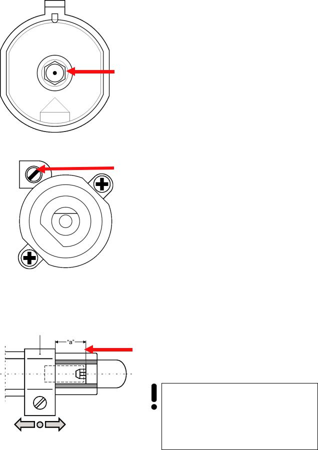
1 – To replace the nozzle: screw out the nozzle (use screw tip N° 7) and replace it with another one in compliance with the available type of gas (see the table 1).
2 – To adjust the burners: Switch on gas and select
2“Sparing flame”. For adjustment, use a 2,5 mm-screw tip.
3 – To replace the nozzle in the oven: See table 1 “a” to adjust air supply correctly.
Table 1
|
Type of |
|
|
|
Burner: type / diameter |
|
« » |
|||
|
gas |
|
|
Small |
|
Normal |
|
Big |
Oven |
|
|
Natural gas |
|
0,75 |
|
1,09 |
1,24 |
1,3 |
3 |
||
|
Liquid gas |
|
0,52 |
|
0,67 |
0,84 |
0,84 |
10 |
||
|
|
|
|
|
|
|
|
|
||
|
Gas |
|
Adjusting from liquid |
|
Adjusting from natural |
|||||
|
|
|
gas to liquid gas |
|||||||
|
supply |
|
|
gas to natural gas |
|
|||||
|
|
|
|
|
|
|
||||
|
|
|
|
|
|
|
|
|
||
|
Full |
|
|
Nozzle burner 1 |
|
Nozzle burners 1 |
||||
|
|
|
|
Replace in compliance |
||||||
|
Replace in compliance |
|
||||||||
|
flame |
|
|
with Table 1 |
|
with Table 1 |
|
|||
|
|
|
|
|
|
|
|
|||
|
|
|
|
|
|
|
|
|
||
|
Saving |
|
Regulating needle 2 |
|
Adjusting needle 2 |
|||||
3 |
|
|
Screw in against the |
|||||||
flame |
Screw out slightly and |
|
||||||||
|
stop and check up gas |
|||||||||
|
|
|
adjust the flame size |
|
supply |
|
||||
|
|
|
|
|
|
|
|
|
||
|
|
|
|
|
|
|
|
|
|
|
Attention! (A hint for the serviceman) The adjustment of the cooker to another gas type should be registered at the connection place.
Issue and attach a label with the gas type which the cooker has been adjusted to.
12
|
|
DE |
|
|
|
RU |
|
ANPASSUNG AN ANDERE GASARTEN |
|
|
|
||||
|
|
|
|
' |
|
|
|
Diese Herde sind mit Gasbrennern ausgestattet, die |
& , |
||||||
von der Herstellerfabrik zum Verbrennen des in |
- , |
||||||
Ihrem Land benutzten Erdgases angepasst sind. Der |
. / |
||||||
Gastyp ist in dem Typenschild, das an der Rückwand |
|
. |
( |
|
|||
des Herdes angebracht ist, angegeben. |
|
. |
|
||||
Um die Gasbrenner einzustellen, sind Drehregler der |
7 |
||||||
Gashähne abzunehmen. |
|
|
. |
|
|
||
Die Einstellelemente des Backofenbrenners sind |
7 |
||||||
nach |
dem |
Herausschieben |
des |
|
|
||
Backofenraumbodens zugänglich. |
|
7 |
|||||
Um den Herd an eine andere Gasart anzupassen; |
, : |
|
|
|
|||
sind folgende Tätigkeiten auszuführen: |
|
( . 1), |
|
||||
Düsen auswechseln (siehe Tabelle 1 ), |
|
& , |
|||||
8reduzierten Ventildurchfluss nachstellen, |
|
. |
|||||
8Luftzufuhr zum Backofenbrenner nachstellen. |
|
|
|
|
|
||
1 - Austausch der Brennerdüse – Düse mit dem |
1 - ( & – & |
||||||
Sondersteckschlüssel SW7 herausdrehen und gegen |
$ 7 |
||||||
eine neue Düse austauschen, welche der Gasart |
, $ ( . |
||||||
entspricht (siehe Tabelle 1). |
|
1). |
|
|
|
||
2 - Regulierung der Brenner erfolgt mittels eines 2,5 |
2 - " & |
||||||
mm Regelschraubendrehers beim angezündeten && & «! Brenner, der auf „Sparflamme“ eingestellt ist. »,
2,5 .
3 - Austausch der Brennerdüse vom Backofen. Regulierung von Luftzufuhr (siehe Tabelle 1 «a»).
Tabelle 1
Gasart |
|
Düse Typ / Durchmesser |
|
« » |
|||||||
Spar |
|
Normal |
|
Stark |
|
Backofenbrenner |
|||||
|
|
|
|
|
|||||||
Erdgas |
0,75 |
|
1,09 |
|
1,24 |
|
1,3 |
|
3 |
||
Flüssiggas |
0,52 |
|
0,67 |
|
0,84 |
|
0,84 |
|
10 |
||
|
|
|
|
|
|
||||||
|
|
Umstellung vom |
|
|
Umstellung vom |
||||||
Brenner |
|
Flüssiggas |
|
|
|
Erdgas auf |
|
||||
|
|
auf Erdgas |
|
|
|
Flüssiggas |
|
||||
Volle |
|
Brenndüse 1 gegen |
|
Brennerdüse 1 gegen |
|||||||
|
eine entsprechende |
|
eine entsprechende |
||||||||
Flamme |
|
gemäß der Tab.1 |
|
|
gemäß derTab.1 |
||||||
|
|
auswechseln |
|
|
|
auswechseln |
|||||
|
|
Einstellnadel 2 ein |
|
Einstellnadel 2 leicht |
|||||||
Spar |
|
|
bis zum Anschlag ein- |
||||||||
|
wenig heraus- |
|
|||||||||
|
|
schrauben und die |
|||||||||
flamme |
|
schrauben und die |
|
||||||||
|
|
|
Flammengröße |
||||||||
|
|
Flammengröße |
|
|
|||||||
|
|
|
|
|
überprüfen |
|
|||||
|
|
nachstellen |
|
|
|
|
|||||
|
|
|
|
|
|
|
|
||||
|
|
|
|
|
|
|
|
|
|
|
|
Achtung! (Hinweis für den Installateur) Die Umstellung des Herdes auf eine andere Gasart ist im Herdanschlusszeugnis zu vermerken.
Nach der Regulierung ist das Etikett mit dem Hinweis auf die Gasart, auf die der Herd angepasst wurde, aufzukleben.
3 - ( & –
( . 1 – « »).
/ 1
/ |
3 / |
|
« » |
||||
|
*. |
|
. |
|
|||
|
|
|
|||||
|
0,75 |
1,09 |
1,24 |
1,3 |
3 |
||
- |
0,52 |
0,67 |
0,84 |
0,84 |
10 |
||
|
|
|
|
|
|||
|
|
* |
|
* - |
|||
|
- |
|
|
||||
|
|
|
|||||
|
|
|
- |
||||
|
|
|
|||||
0 |
|
# 1 |
|
# 1 |
|||
|
|
|
|
|
|||
|
|
|
|
||||
|
$ |
|
$ |
||||
|
|
|
|||||
|
/ 1 |
|
. 1 |
||||
|
|
|
|||||
|
|
"$ |
|
"$ |
|||
|
|
|
2 - |
||||
4 |
|
2 |
|
||||
|
|
- |
|||||
|
|
|
|
||||
|
|
|
|
||||
|
|
|
|
|
|||
|
|
|
|||||
|
|
|
|
||||
|
|
|
|
|
|||
|
|
|
|
|
|
||
$%&$ ! ( )
.
&
! ,
.
13
EN
SAFETY CONDITIONS
Please, keep watch over children as long as the gas cooker is in operation. Children are unaware of operating rules. Hot gas burners, hot oven cavity, oven door pane, pans and pots with hot liquid on the grid above the burners can cause a skin-burn.
Connection cords of electric appliances, e.g. a mixer, should not get in contact with hot parts of the cooker.
Don’t put inflammable materials into the bottom drawer of the cooker, since they can get inflamed while the cooker is in operation.
Keep watching the cooker while frying: oils and fats can get inflamed due to overheating.
If faults occur, further operation is not allowed until the appliance has been repaired by an authorized serviceman.
Don’t turn on the valve of the gas inlet or gas cylinder before you make sure that the gas burners are switched off.
Keep the burners clean. The overflown food or residues must be immediately removed after the burners get cold.
Don’t put pans directly onto the burners.
The weight of a pan put on the grid above a burner should not exceed 10 kg; the total weight of the pans over the four burners should be max. 40 kg.
Don’t strike the handles and the burners.
Don’t put more than 15 kg on the open oven door.
Unauthorized persons are not allowed to carry on amedments or repair the cooker.
It is not allowed to turn on the knobs of the burners if the electric ignition is out.
Don’t blow out the flame of the burner!
Users are not allowed to adjust the cookers to different gas type on their own, move the cooker to another place or make changes in the gas supply system. These operations can be carried on only by an authorized serviceman.
14
DE |
RU |
SICHERHEITSBEDINGUNGEN |
' |
Während des Gasherdbetriebs auf Kinder &,
|
aufpassen, weil sie über keine Kenntnisse |
|
, |
|||||
|
hinsichtlich die |
Herdbedienung verfügen. |
|
& . 3 |
||||
|
Insbesondere |
heiße |
Kochstellenbrenner, |
|
, , , |
|||
|
Backofenraum, Rost, Türscheibe, Kochgeschirr |
|
, $ |
|||||
|
mit heißer Flüssigkeit können bei Kindern |
|
& & |
|||||
|
Verbrennungen verursachen. |
|
|
. |
|
|||
|
Es ist zu beachten, dass kein Anschlusskabel |
|
|
! |
||||
|
anderer Elektrogeräte (wie z.B. eines Mixers) |
|
. |
|||||
|
mit heißen Herdteilen in Kontakt kommt. |
|
|
& . |
||||
|
Leichtentflammbare Materialien dürfen nicht in |
|
* & $ |
|||||
|
der Schublade aufbewahrt werden; während |
|
, |
|||||
|
des |
Backofenbetriebes |
könnten |
sie |
|
. |
||
|
aufflammen. |
|
|
|
|
* |
||
Das Kochfeld während des Bratens nicht ohne |
||||||||
|
Aufsicht lassen. Überhitzte Öle und Fette sind |
|
&. ) & |
|||||
|
leichtentzündlich! |
|
|
|
|
- ! |
||
Falls der Herd beschädigt wird, darf er erst & ,
|
wieder benutzt werden, nachdem die |
|
! |
|
||||||
|
Beschädigung |
von |
einem |
qualifizierten |
|
|
|
& |
||
|
Fachmann beseitigt ist. |
|
|
|
|
. |
||||
Den |
Gasabsperhahn |
an |
der |
|
* |
|||||
|
Gasanschlussstelle bzw. an der Gasflasche |
|
|
|||||||
|
niemals öffnen ohne sicherzustellen, dass alle |
|
, |
|||||||
|
Gassperventile zugedreht sind. |
|
|
|
. |
|
|
|||
Gasbrenner |
nicht |
überfluten |
bzw. |
|
. . |
|||||
|
verunreinigen |
lassen. |
Beschmutzte |
|
( |
|||||
|
Gasbrenner sofort nach dem Abkühlen reinigen |
|
|
& |
||||||
|
und abtrocknen. |
|
|
|
|
|
. |
|
|
|
Kein Geschirr direkt auf die Gasbrenner *
aufstellen. |
. |
Auf dem Rost über einem Gasbrenner kein , $ 9
Geschirr aufstellen, dessen Gewicht 10 kg |
& 10 , |
überschreitet; das Gesamtgewicht vom |
$ 9 |
Geschirr, das auf dem ganzen Rost aufgestellt |
40 . |
ist, darf nicht mehr als 40 kg sein.
|
Drehregler und Gasbrenner nicht aufschlagen. |
|
* . |
||||||
|
Keine Gegenstände auf die aufgeklappte |
* |
|||||||
|
Backofentür stellen, die schwerer als 15 kg |
|
15 . |
||||||
|
sind. |
|
|
|
|
($ |
|||
Es ist streng verboten, den Gasherd von nicht |
|||||||||
|
speziell |
ausgebildeten |
Personen |
zu |
|
|
|
, |
|
|
modifizieren bzw. reparieren lassen. |
|
|
. |
|
||||
Es ist verboten, die Gasabsperhähne der ($
Kochstellen und des Backofens zu öffnen, ohne ein angezündetes Streichholz oder Gaszünder in der Hand zu haben.
Gasbrennerflamme nie durch Blasen löschen.
Eigenwillige Anpassung vom Gasherd an einen anderen Gastyp, Verstellung des Herdes sowie Einführung von Änderungen in die Gasversorgungsleitung sind verboten. Diese Tätigkeiten dürfen ausschließlich von einem autorisierten Installateur durchgeführt werden.
! & &&
.
($ .
($
,
, &
. 4
.
15
EN
Don’t let children and persons who are not informed about the operation instructions to operate the cooker.
Watch the pans while boiling in order not to extinguish the burners.
In case of gas leak, it is not allowed:
to strike a match, smoke, switch on and off an electric receiver (a door bell, a light switch) as well as use other electrical or mechanical appliances which can cause electric or chugging spark. In this case, immediately shut off gas supply (turn off the valve of the gas cylinder or the switch which cuts off the connection to the gas supply), air the room and contact an authorized person.
Don’t attach any cables to the gas appliance.
If the gas leaking out of a nontight junction gets inflamed, immediately cut off the gas supply by turning off the valve of the gas cylinder or the switch which disconnects gas supply).
In case of damage: air the room, disconnect the appliance from the power supply and repair the fault.
If the gas leaking out of the nontight junction of the gas cylinder gets inflamed, wrap the cylinder with a wet blanket to extinguish the flame and turn off the valve (stopcock) of the gas cylinder. Further use of the damaged gas cylinder is not allowed.
If you don’t use the gas cooker for a few days, disconnect it from the gas supply by turning off the stop valve. In case of a gas cylinder, turn off the stopcock every time after the use.
The gas supply should provide the cooker with the type of gas it has been adjusted to in plant. Information about the gas type which the cooker has been adjusted to is registered on the data plate on the cookers back.
16
DE |
RU |
Kleinen Kindern und Personen, welche mit der |
* , & |
Gebrauchsanweisung des Gasherdes nicht |
, |
vertraut sind, den Gasherd nicht bedienen |
! . |
lassen.
Während des Kochens beachten Sie, dass - ,
Übergelaufenes die Gasbrenner nicht ablöscht. |
. |
Im Falle eines Gasleckverdachtes ist folgendes |
(")*& + ! , $- ) *.$ /&,& "0,-: |
untersagt: |
& , , |
Streichhölzer anzünden, Zigaretten rauchen, |
|
Elektrogeräte einund ausschalten (Klingelund |
! ( |
Lichtschalter) sowie sonstige elektrische und |
$ ), & |
mechanische Geräte benutzen, die Elektround |
! - |
Schlagfunkentstehung verursachen können. In so |
, $ !- |
einem Fall muss der Gasabsperrhahn der |
. |
Gasanschlussleitung bzw. der Gasflasche sofort |
|
zugedreht und der Raum gelüftet werden; danach |
( |
muss die Schadensursache von einem |
, $ ) |
autorisierten Fachmann beseitigt werden. |
$ , , $ |
|
. |
Keine Erdungsleitungen dürfen an die *
Gasanschlussleitung angeschlossen werden. |
. |
|
||||||||||
Falls sich das aus einer undichten |
, $ |
|||||||||||
Gasinstallation |
entweichende |
Gas entzündet, |
|
|
, |
|
||||||
ist |
der |
|
Gaszulauf |
mittels |
des |
|
||||||
Gasabsperrhahnes sofort abzusperren. |
|
$ |
||||||||||
In jeder Situation, wo eine technische Störung |
, $ |
|||||||||||
& , |
||||||||||||
auftritt, ist der Herd von der Stromversorgung |
, |
|
|
|||||||||
unbedingt |
zu |
trennen |
(wobei |
das |
|
! |
, |
|||||
obenangeführte Prinzip zu beachten ist) und |
$ |
|||||||||||
die |
Störung |
|
bei |
einer |
autorisierten |
. |
|
|||||
Reparaturstelle anzumelden.
Falls sich das aus einem undichten , $
Gasflaschenventil |
entweichende |
Gas |
, - |
|
entzündet, ist die Gasflasche mit einer feuchten |
: |
|||
Decke zu bedecken, um die Flamme zu |
& , |
|||
löschen und die Gasflasche abzukühlen. |
. ($ |
|||
Wiedergebrauch |
einer |
beschädigten |
! & . |
|
Gasflasche ist streng verboten.
Falls der Gasherd einige Tage nicht genutzt ,
werden soll, ist der Hauptabsperrhahn der |
&$ , |
|||
Gasanschlußleitung zuzumachen. Wenn der |
, |
|||
Gasherd von einer Gasflasche versorgt wird, |
– & |
|||
muss das Gasflaschenventil nach jedem |
. |
|
||
Gebrauch zugedreht werden. |
|
|
|
|
Ihr Gasherd soll an die Gasanschlußleitung |
"$& ! "# & 12 0 + !( !$& . &. %) |
|||
angeschlossen werden, welche mit der Gasart |
# $+) /&,&, & . 23 & &( & |
|||
versorgt ist, für die Ihr Gasherd werksseitig |
,&4 ! %. 5 %&6$- $+ /&,&, & |
|||
ausgelegt ist. Die Information über die Gasart, |
. 23 |
+"$& |
&( & |
,&4 ! %, |
an die Ihr Gasherd werksseitig angepasst |
&7 !$(- & ,&4 !(. 3 &1"$*. & ,&! 3 |
|||
worden ist, ist dem Typenschild zu entnehmen. |
( . +"$2. |
|
|
|
Das Typenschild befindet sich auf der
Rückwand des Gerätes.
17
EN
1 |
|
1 |
BRIEF DESCRIPTION |
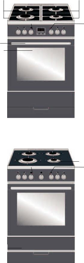
LOCATION DRAWING
Arrangement of functional assemblies
|
8 |
|
|
|
|
|
|
|
|
|
5 |
|
1 |
Gas burners |
||||||
|
|
|
|
|||||||||||||||||
|
|
|
|
|
|
|
|
|
|
|
|
|
|
|
|
|
9 |
|
||
|
|
|
|
|
|
|
|
|
|
|
|
|
|
|
|
|
|
|||
|
|
|
|
|
|
|
|
|
|
|
|
|
|
|
|
|
|
|||
|
|
|
|
|
|
|
|
|
|
|
|
|
|
|
|
|
|
|
2 |
Knobs of the gas burners control |
|
|
|
|
|
|
|
|
|
|
|
|
|
|
|
|
|
|
|
||
|
2 |
|
|
|
|
|
|
|
|
|
|
|
|
|
|
2 |
|
|
||
|
|
|
|
|
|
|
|
|
|
|
|
|
|
|
|
|
3 |
Knobs of the oven temperature control |
||
|
|
|
|
|
|
|
|
|
|
|
|
|
|
|
||||||
|
|
|
|
|
|
|
|
|
|
|
|
|
|
|
|
|
|
|
||
|
3 |
|
|
|
|
|
|
|
|
|
|
|
|
|
|
4 |
|
|
||
|
|
|
|
|
|
|
|
|
|
|
|
|
4 |
Knobs of the oven operating functions |
||||||
|
|
|
|
|
|
|
|
|
|
|
|
|
|
|
|
|
|
|
||
|
|
|
|
|
|
|
|
|
|
|
|
|
|
|
|
|
|
|
||
|
|
|
|
|
|
|
|
|
|
|
|
|
|
|
|
|
10 |
5 |
Pilot light ON / OUT (yellow) |
|
|
|
|
|
|
|
|
|
|
|
|
||||||||||
|
|
|
|
|
|
|
|
|
|
|
|
|
|
|
|
|
|
|
|
|
|
6 |
|
|
|
|
|
|
|
|
|
|
|
|
|
|
|
|
|
6 |
Oven door |
|
|
|
|
|
|
|
|
|
|
|
|
|
|
|
|
|||||
|
|
|
|
|
|
|
|
|
|
|
|
|
|
|
|
|
|
|
||
|
|
|
|
|
|
|
|
|
|
|
|
|
|
|
|
|
|
|
||
|
|
|
|
|
|
|
|
|
|
|
|
|
|
|
|
|
|
|
7 |
Drawer |
|
|
|
|
|
|
|
|
|
|
|
|
|
|
|
|
|
|
|
8 |
Oven temperature - pilot light (red) |
|
|
|
|
|
|
|
|
|
|
|
|
|
|
|
|
|
|
|
9 |
Control panel |
7 |
|
|
|
|
|
|
|
|
|
|
|
|
|
|
|
|
|
|
||
|
|
|
|
|
|
|
|
|
|
|
|
|
|
|
|
|
|
10 |
Electronic timer |
|
|
|
|
|
|
|
|
|
|
|
|
|
|
|
|
|
|
|
|||
|
|
|
|
|
|
|
|
|
|
|
|
|
|
|
|
|
|
|
||
|
|
|
|
|
|
|
|
|
|
|
|
|
|
|
|
|
|
|
||
|
|
|
|
|
|
|
|
|
|
|
|
|
|
|
|
|
|
|
11 |
Timer |
|
|
|
|
|
|
|
|
|
|
|
||||||||||
|
1 |
|
|
|
|
1 |
|
|
|
|
|
|||||||||
|
|
|
|
|
|
|
|
|
|
|
|
|
|
|
|
|
|
|
|
|
|
|
|
|
|
|
|
|
|
|
|
|
|
|
|
|
|
|
|
|
|
|
|
|
|
|
|
|
|
|
|
|
|
|
|
|
|
|
|
|
|
|
8 |
|
|
|
|
|
5 |
|
||||||||
|
|
|
|||||||||||||
|
|
|
|
|
|
|
|
|
|
9 |
|
||||
|
|
|
|
|
|
|
|||||||||
|
|
|
|
|
|||||||||||
|
|
|
|
|
|
|
|
|
|
|
|
|
|
|
|
|
|
|
|
|
|
|
|
|
|
|
|
|
|
|
|
2 |
|
|
|
|
|
|
|
|
|
|
|
|
2 |
|
|
|
|
|
|
|
|
|
|
|
|
|
|
|
|||
|
|
|
|
|
|
|
|
|
|
|
|
|
|||
3 |
|
|
|
|
|
|
|
|
|
4 |
|
|
|||
|
|
|
|
|
|
|
|
|
|
||||||
|
|
|
|
|
|
|
|
|
|
|
11 |
|
|||
|
|
|
|
|
|
||||||||||
|
|
|
|
|
|
||||||||||
|
|
|
|
|
|
|
|
|
|
|
|
|
|
|
|
|
|
|
|
|
|
|
|
|
|
|
|
|
|
|
|
6 |
|
|
|
|
|
|
|
|
|
|
|
|
|
|
|
|
|
|
|
|
|
|
|
|
|
|
|
|
|
|
|
|
|
|
|
|
|
|
|
|
|
|
|
|
|
|
|
7
Depending on the technical equipment, different models are provided with different control panels and relevantly arranged operating elements.
18
|
DE |
|
RU |
KURZBESCHREIBUNG |
|
||
GESAMTANSICHT |
8 |
||
Anordnung von Funktionsbaugruppen |
$% &,% 9$ 5) .6$&"0 27 |
||
|
|
)," 4 |
|
1 |
Gasbrenner |
1 |
3 |
2 |
Drehregler für Kochstellbrennern |
2 |
" |
3 |
BackofenTemperaturwähler |
3 |
" |
4 |
Drehregler des Backofenbetriebsfunktionen |
4 |
" & ( |
|
|
|
) |
5 |
Betrieb - Kontrollleuchte ON/OFF (gelb) |
5 |
% |
|
|
|
(&) |
6 |
Backofen |
6 |
' |
7 |
Schublade |
7 |
& $ |
8 |
Backofentemperatur - Kontrolleuchte (rot) |
8 |
% |
|
|
|
( ) |
9 |
Bedienblende |
9 |
a e |
10 |
Digitale Zeitschaltuhr |
10 |
$ |
11 |
Taimer |
11 ) |
|
Verschiedene Modelle, je nach ihrer technischen Ausrüstung, sind mit |
- , |
|||||
verschiedenen |
Bedienblenden |
versehen, |
an |
denen |
die |
, |
Bedienelemente sinnvoll angeordnet sind. |
|
|
|
$ ! . |
||
19
1 |
4 |
5 |
|
|
|
2 |
6 |
3 |
|
||
1 |
|
|
4 |
|
5 |
||
|
|
|
|||||
|
|
|
|
||||
|
|
|
|
|
|
|
|
|
|
|
|
|
|
|
|
2 6 3
1 |
|
|
4 |
7 |
5 |
|
|
|
|||
|
|
|
|
|
|
|
|
|
|
|
|
|
|
|
|
|
|
28 9 10 3
1 |
|
|
4 |
7 |
5 |
|||||
|
|
|
|
|||||||
|
|
|
|
|
|
|
|
|
|
|
|
|
|
|
|
|
|
|
|
|
|
|
|
|
|
|
|
|
|
|
|
|
|
|
|
|
|
|
|
|
|
|
|
|
|
|
|
|
|
|
|
|
|
|
2 |
8 |
9 |
10 |
3 |
EN
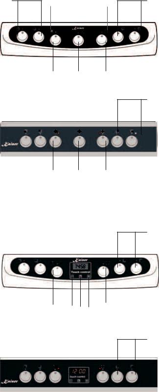
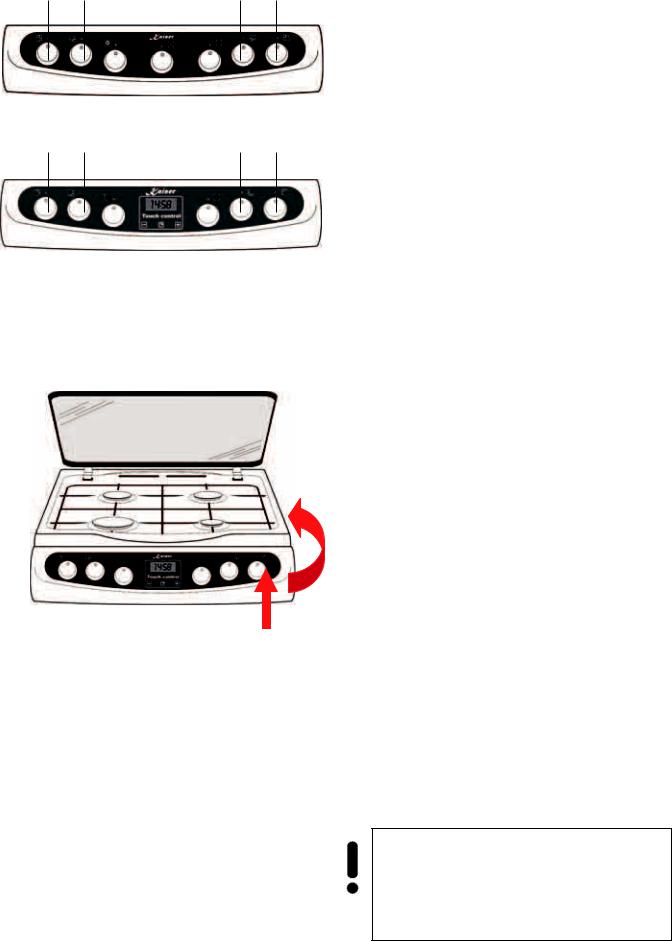
CONTROL PANEL
1
Models Exclusive and PLATIN: Control Panel with mechanical Timer
1
1Models Exclusive und PLATIN : Control Panel with electronic sensor timer
1.Knobs of gas burners
2.Knob of the oven temperature control
3.Knob of the oven operating functions
4.Control light ON/OFF (yellow)
5.Oven operation - Control light (red)
6.Timer (if available)
7.Digital programming device
18. Button « - »
9.Button “Function selection”
10.Button « + »
20
DE |
RU |
BEDIENBLENDE |
|
Bedienblende von Modellen Exclusive und PLATIN mit Kurzzeitwecker
Bedienblende von Modellen Exclusive und PLATIN mit elektronischer Zeitschaltuhr mit Sensorbedienung
& "$ )+ &4"$- % ! " 3 Exclusive $ PLATIN ( %$)$. %
& "$ )+ &4"$- % ! " 3 Exclusive $ PLATIN ( ( ( 2% :" . 2%
+ / &%%$ );9$% )( 3( 4 %
1. |
Drehregler für Gasbrenner |
1 |
" |
|
|
|
|
2. |
Drehregler “Backofentemperatur” |
2 |
" “/ ” |
3. |
Drehregler “Backofenbetriebsfunktionen” |
3 |
" “" & ” |
|
oder „Backofenlicht“ |
|
„- $ “ |
4. |
Kontrollleuchte ON/OFF (gelb) |
4 |
% / (&.) |
5. |
Backofenbetrieb Kontrollleuchte (rot) |
5 |
% |
|
|
|
( .) |
6. |
Kurzzeitwecker (falls vorhanden) |
6 |
) ( ) |
7. |
Digitale Zeitschaltuhr |
7 |
' $ |
|
|
|
|
8. |
Drucktaste « - » |
8 |
% « - » |
9. |
Betriebdrucktaste |
9 |
% |
10. Drucktaste « + » |
10 |
% « + » |
|
21
|
|
|
|
|
|
|
|
|
EN |
|
|
|
|
|
|
|
|
|
|
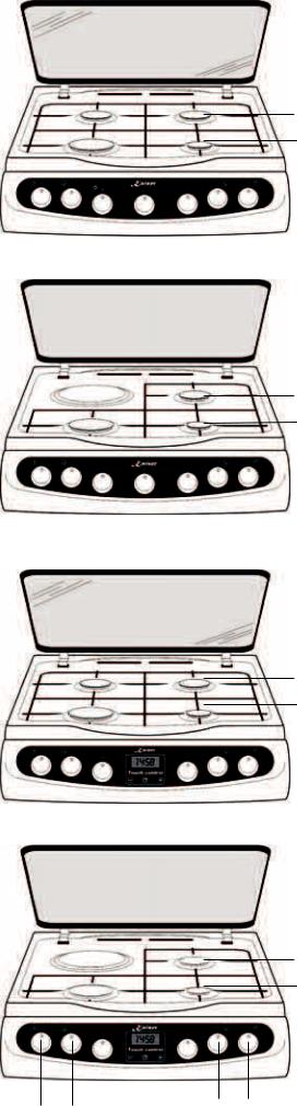
EQUIPMENT |
|
|
|
|
|
|
|
|
|
|
GAS BURNERS AND RELEVANT |
|
|
|
|
|
|
|
|
|
|
OPERATING ELEMENTS |
|
2 |
|
|
|
|
|
|
4 |
HGG 60501*, HGG 60511*, HGG 60521*, |
||
|
|
|
|
|
|
|
HGG 64521*, HGG 61511*, HGG 61531* |
|||
1 |
|
|
|
|
|
|
3 |
|||
|
|
|
|
|
|
1 - Knob of the gas burner in front (left) |
1,0 kW |
|||
|
|
|
|
|
|
|
|
|
||
|
|
|
|
|
|
|
|
|
2 - Knob of the gas burner behind (left) |
1,8 kW |
|
|
|
|
|
|
|
|
|
3 - Knob of the gas burner behind (right) |
1,8 kW |
|
|
|
|
|
|
|
|
|
||
|
|
|
|
|
|
|
|
|
4 - Knob of gas burner in front (right ) |
2,8 kW |
|
|
|
|
|
|
|
|
|
|
|
1 |
2 |
|
|
|
|
|
|
|||
3 |
4 |
|
|
|||||||
|
|
|
|
|
|
|
|
|
HGE 60301*, HGE 60309* |
|
2 |
|
|
|
|
|
|
|
|
1 - Knob of the gas burner in front (left) |
1,0 kW |
|
|
|
|
|
|
4 |
2 - Knob of the electrical cooking zone behind (left) |
|||
|
|
|
|
|
|
|
Ø180 mm 1,2 kW |
|
||
|
|
|
|
|
|
|
|
|
|
|
1 |
|
|
|
|
|
|
|
3 3 - Knob of the gas burner behind (right) |
1,8 kW |
|
|
|
|
|
|
|
|
||||
|
|
|
|
|
|
|
|
|
4 - Knob of the gas burner in front (right) |
2,8 kW |
|
|
|
|
|
|
|
|
|
|
|
|
|
3 |
4 |
|||
1 |
2 |
|||||||
|
|
|
|
|||||
HGE 61500*, HGE 60500*, HGE 60508*, HGE 64508*
|
|
|
1 – Knob of the gas burner in front (left) |
|
2 |
|
4 |
1,0 kW |
|
|
|
2 - Knob of the gas burners behind (left) |
1,8 kW |
|
|
|
|
||
1 |
|
3 3 - Knob of the gas burner behind (right) |
1,8 kW |
|
|
||||
|
|
|
4 - Knob of the gas burner in front (right) |
2,8 kW |
|
|
|
|
|
|
|
|
|
|
|
|
|
|
|
|
3 |
4 |
|
|
||
1 |
2 |
HGE 60306* |
|
|||||||
|
|
|
|
|
||||||
|
|
|
|
|
|
|
|
|
|
|
|
|
|
|
|
|
|
|
|
1 - Knob of the gas burner in front (left) |
1,0 kW |
|
|
|
|
|
|
|
|
|
2 - Knob of the electrical cooking zone behind (left) |
|
|
|
|
|
|
|
|
|
|
Ø180 mm 1,2 kW |
|
2 |
|
|
|
|
|
|
4 |
3 - Knob of the gas burner behind (right) |
1,8 kW |
|
|
|
|
|
|
|
|
4 - Knob of the gas burner in front (right) |
2,8 kW |
||
|
|
|
|
|
|
|
||||
1 |
|
|
|
|
|
|
3 |
|
|
|
|
|
|
|
|
|
|
|
|||
* - Modifikation
1 |
2 |
3 |
4 |
22
DE
AUSSTATUNG
KOCHFELD MIT GASBRENNERN
HGG 60501*, HGG 60511*, HGG 60521*, HGG 64521*, HGG 61511*, HGG 61531*
1 - Drehregler für Gasbrenner vorne links
1,0 kW
2 - Drehregler für Gasbrenner hinten links
1,8 kW
3 - Drehregler für Gasbrenner hinten rechts
1,8 kW
4 - Drehregler für Gasbrenner vorne rechts
2,8 kW
HGE 60301*, HGE 60309*
1 |
- Drehregler für Gasbrenner vorne links |
|
1,0 kW |
2 |
- Drehregler für Elektrokochfeld hinten links |
|
Ø180 mm 1,2 kW |
3 - Drehregler für Gasbrenner hinten rechts
1,8 kW
4 - Drehregler für Gasbrenner vorne rechts
2,8 kW
RU
<
'
HGG 60501*, HGG 60511*, HGG 60521*, HGG 64521*, HGG 61511*, HGG 61531*
1 - "
- epe 1,0
2 - "
- 1,8
3 - "
- 1,8
4 - "
- 2,8
HGE 60301*, HGE 60309*
1 |
- " |
|||
|
|
- epe |
1,0 |
|
2 |
- " !. |
|||
e |
- |
|
||
|
|
Ø180 mm |
1,2 |
|
3 |
- " |
|||
|
|
- |
1,8 |
|
4 |
- " |
|||
|
|
- |
2,8 |
|
HGE 61500*, HGE 60500*, HGE 60508*, HGE 64508*
1 - Drehregler für Gasbrenner vorne links
1,0 kW
2 - Drehregler für Gasbrenner hinten links
1,8 kW
3 - Drehregler für Gasbrenner hinten rechts
1,8 kW
4 - Drehregler für Gasbrenner vorne rechts
2,8 kW
HGE 61500*, HGE 60500*, HGE 60508*, HGE 64508*
1 - "
- epe 1,0
2 - "
- 1,8
3 - "
- 1,8
4 - "
- 2,8
HGE 60306* |
HGE 60306* |
|
|
||
1 - Drehregler für Gasbrenner vorne links |
1 |
- " |
|||
1,0 kW |
|
|
- epe |
1,0 |
|
2 - Drehregler für Elektrokochfeld hinten links |
2 |
- " !. |
|||
Ø180 mm 1,2 kW |
e |
- |
|
||
|
|
|
Ø180 mm |
1,2 |
|
3 - Drehregler für Gasbrenner hinten rechts |
3 |
- " |
|||
1,8 kW |
|
|
- |
1,8 |
|
4 - Drehregler für Gasbrenner vorne rechts |
4 |
- " |
|||
2,8 kW |
|
|
- |
2,8 |
|
* - Die Modifikationen |
* - ) |
|
23
1 |
2 |
3 |
4 |
1 |
2 |
3 |
4 |
EN
GAS COOKING ZONES CONTROL
Before using your new appliance, we ask you to do the following:
Read carefully the operating instructions and safity conditions.
Remove the packaging, empty the drawer, clean the oven cavity in order to eliminate preservative agents.
Check up functional efficiency of the stop valves (installation junction and that of the cooker) as well as the other control units.
Heat up the oven (at 250° C for 30 min.)
Service the cooker only in case of duly ventilation.
The cooking zones control is achieved by means of knobs 1, 2, 3 and 4 set up on the control panel of the cooker.
All gas cookers XL 500 are provided with the system of electrical ignition operated by means of knobs.
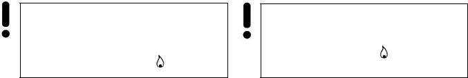
To switch on a gas burner:
Press the corresponding knob of the selected burner against the stop and turn it to the left up to the position strong gas supply.
Keep the switch pressed till the burner ignites.
After the burner has ignited, let the knob go and select the required flame volume (e.g. sparing flame).
To switch off the burner after the food is ready turn on the knob to the right (position “off”).
If your appliance is provided with gas control system for the burners and the oven, to ignite a burner press the knob against the stop and keep it in the position “strong gas supply” to activate the control system.
Attention! It is not allowed to adjust gas supply between the position burner off  and the position strong gas supply
24
DE |
RU |
GEBRAUCH VOM GASKOCHFELD |
<' ' |
|
< |
Bevor Sie den Herd zum ersten Mal in Betrieb |
& |
nehmen, muss folgendes gemacht werden: |
, : |
Sich mit der Gebrauchsanweisung, und
|
insbesondere mit den Sicherheitsbedingungen |
|
&. |
||||||
|
vertraut machen. |
|
|
|
|
, & |
|||
Das Gerät auspacken, die Schublade leeren, |
|
& $ , |
|||||||
|
den Backofenraum vom Korrosionsschutzmittel |
|
|
|
$ |
||||
|
reinigen. |
|
|
|
|
$ . |
|
|
|
|
Wirksamkeit von Gasabsperhähnen (an der |
|
|
|
! |
||||
|
Gasanschlussleitung und im Gasherd selbst) |
|
( |
||||||
|
und anderen Steuerelementen überprüfen. |
|
), & ! |
||||||
|
Backofen durchwärmen (bei 250°C, ca. 30 |
|
. |
|
|||||
|
min). |
|
|
|
|
( 250°# 30 |
|||
Den |
Erstbetrieb |
nur |
bei |
ausreichender |
|
.) |
|
|
|
|
Belüftung durchführen. |
|
|
& |
|||||
|
|
|
|
|
|
|
$ . |
||
Die Kochzonensteuerung erfolgt mittels Drehregler |
& |
||||||||
1, 2, 3 und 4, die auf der Bedienblende des Herdes |
$ 1, 2, 3 |
||||||||
eingerichtet sind |
|
|
|
$ 4, |
|||||
Alle Gasherde XL 500 sind mit elektrischem |
. |
|
|||||||
|
|
|
|
||||||
Gaszünder-System |
in |
den |
Drehreglern |
XL 500 |
|||||
ausgerüstet. |
|
|
|
! & . |
|||||
Um den Brenner anzuzünden: |
|
|
7 & &: |
|
|||||
Den |
Drehregler des gewählten |
Brenners bis |
& |
|
|||||
|
zum fühlbaren Anschlag hineindrücken und |
|
|||||||
|
danach nach links bis zur Position Volle |
1 "0=&- + !&*& /&,& , |
|
||||||
|
Flamme umdrehen, |
|
|
|
|
|
|
|
|
Den Drehregler zum Anschlag hineingedrückt |
& & & , |
||||||||
halten, bis zum Gasaufflammen,
nach dem Aufflammen des Gasbrenners den ,
‘Drehregler loslassen und die gewünschte
Flammengröße einstellen (z.B. Spar-Flamme). ( , >. % +"&%- )
Nach dem Kochvorgang den Kochstellenbrenner ausschalten, indem der Drehregler nach rechts umgedreht wird. (Position «Ausgeschaltet»).
Bei |
den |
Gasherdmodellen, |
deren |
|
Kochstellenbrenner |
mit |
einem |
||
Gasausflussschutz ausgerüstet sind, muss der Drehregler während des Anzündens ca. 2-10 Sekunden lang in der Position „Volle Flamme” bis zum Anschlag hineingedrückt gehalten werden, damit der Gasausflussschutz anspringen kann.
Achtung! Es ist verboten, die Flammengröße durch die Wahl einer Drehknebelposition im Bereich zwischen der Position erlöschte Flamme  und der Position Volle Flamme
einzustellen.
, (&
« »).
% ! "-7 +"$ , ( &9 27 /&,-. " % / " . $ !)7 4.$ +"$2, (" !) 4 4 %- + &6$$ ,$/&$- ! #& 0 )*.) & 3 ! )+ & 4 *$ 2-10 (.. 4 + " #$$ «1 "0=&- + !&*& /&,&», * 12 ,&9$& &.$4$ 4&"&(0.
$%&$ ! ($
& &
+ )= &- / ".&  &
&
1 "0=&- + !&*& /&,& .
.
25
EN
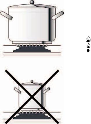
Correctly adjusted burners have a light blue flame with a distinct internal cone.
Flame volume is adjusted by knobs:
big flame
small flame ("sparingl")
burner is off (gas supply is stopped)
Knobs ensure gradual setting of flame volume.
Remember that the diameter of the pan’s bottom should be bigger than the diameter of flame in the burner. Pans should be covered with lids.
For effective cooking, the utensil’s diameter should be 2,5-3 times bigger that that of the burner. Thus, following diameters correspond to the available burner types:
Small – 90 mm to 150 mm,
Normal – 160 mm to 220 mm,
Strong – 200 mm to 240 mm
The utensils height should not exceed its diameter.
26
 Loading...