

Page 1
Easi-Cladder™
Accessory Manual
JLG
Easi-Cladder™
and
Easi-Cladder™
Plus
Accessory
Manual
P/N - 3128112
January 21, 2004
Page 2

Page 3

FOREWORD
FOREWORD
This manual is a very important to ol! Keep it with the accessory at all times.
The purpose of this manual is to provide owners, users, operators, lessors, and lessees with the precautions
and operating proc edures essential for the safe and proper mac hine operation for its intended purpose.
Due to continuous pro du ct imp ro v em en ts , JLG Industries, Inc. reserves th e ri gh t to make specification cha ng es
without prior notification. Contact JLG Industries, Inc. for updated information.
3128112 – JLG Lift – a
Page 4
SAFETY ALERT SYMBOLS AND SAFETY SIGNAL WORDS
SAFETY ALERT SYMBOLS AND SAFETY SIGNAL WOR DS
This is the Safety Alert Symbol. It is used to alert you to the
potential personal injury hazards. Obey all safety messages
that follow this sym bol to avoid possible injury or de ath
INDICATES AN IMMINENTLY HAZARDOUS SITUATION. IF NOT
AVOIDED, WILL
DECAL WILL HAVE A RED BACKGROUND.
INDICATES A POTENTIALITY HAZARDOUS SITUATION. IF NOT
AVOIDED, COULD
DECAL WILL HAVE AN ORANGE BACKGROUND.
RESULT IN SERIOUS INJURY OR DEATH. THIS
RESULT IN SERIOUS INJURY OR DEATH. THIS
INDICATES A POTENTIALITY HAZARDOUS SITUATION. IF NOT
AVOIDED, MAY
ALSO ALERT AGAINST UNSAFE PRACTICES. THIS DECAL WILL
HAVE A YELLOW BACKGROUND.
RESULT IN MINOR OR MODERATE INJURY. IT MAY
IMPORTANT
INDICATES PROCEDURES ESSENTIAL FOR SAFE OPERATION.
THIS DECAL WILL HAVE A GREEN BACKGROUND.
b – JL G Lift – 3128112
Page 5

SAFETY ALERT SYMBOLS AND SAFETY SIGNAL WORDS
THIS PRODUCT MUST COMPLY WITH ALL SAFETY RELATED BULLETINS. CONTACT JLG INDUSTRIES, INC. OR THE LOCAL AUTHORIZED JLG REPRESENTATIVE FOR INFORMATION REGARDING SAFETY-RELATED BULLETINS WHICH MAY HAVE BEEN ISSUED FOR
THIS PRODUCT.
IMPORTANT
JLG INDUSTRIES, INC. MUST BE NOTIFIED IMMEDIATELY IN ALL INSTANCES WHERE JLG PRODUCTS HAVE BEEN INVOLVED IN AN
ACCIDENT INVOLVING BODILY INJURY OR DEATH OF PERSONNEL OR WHEN SUBSTANTIAL DAMAGE HAS OCCURRED TO PERSONAL PROPERTY OR THE JLG PRO DUCT.
FOR :
•Accident Reporting
•Product Safety Publications
•Current Owner Updates
•Questions Regarding Product Safety
•Standards and Regulatio ns Compliance Information
•Questions Re ga rd in g Spe c ial Product Applications
•Questions Regarding Product Modifications
CONTACT :
Product Safety and Rel iability Department
JLG Industries, Inc.
1 JLG Drive
McConnellsburg, PA 17233
or Your Local JLG Office
(Addresses on back of manual cover)
In USA:
Toll Free: 877-JLG-SAFE
877-554-7233
Outside USA:
717-485-5161
E-mail: ProductSafety@JLG.com
3128112 – JLG Lift – c
Page 6

REVISION LOG
June 9, 2003 – Original Issue of Manual
January 21, 2004 – Manual Revised
REVISION LOG
d – JL G Lift – 3128112
Page 7

TABLE OF CONTENTS
TABLE OF CONTENTS
SUBJECT - PARAGRAPH PAGE NO.
TABLE OF CONTENTS . . . . . . . . . . . . . . . . . . . . . . . . . . . . . . . . . . . . . . . . . . . . . . . . . . . . . . . . . .I
LIST OF FIGURES. . . . . . . . . . . . . . . . . . . . . . . . . . . . . . . . . . . . . . . . . . . . . . . . . . . . . . . . . . . . . II
LIST OF TABLES. . . . . . . . . . . . . . . . . . . . . . . . . . . . . . . . . . . . . . . . . . . . . . . . . . . . . . . . . . . . . . II
EASI-CLADDER™ . . . . . . . . . . . . . . . . . . . . . . . . . . . . . . . . . . . . . . . . . . . . . . . . . . . . . . . . . . . . . 1
FOREWORD . . . . . . . . . . . . . . . . . . . . . . . . . . . . . . . . . . . . . . . . . . . . . . . . . . . . . . . . . . . . . . . . . . . . . . . a
SAFETY ALERT SYMBOLS AND SAFETY SIGNAL WORDS. . . . . . . . . . . . . . . . . . . . . . . . . . . . . . . . . . b
REVISION LOG. . . . . . . . . . . . . . . . . . . . . . . . . . . . . . . . . . . . . . . . . . . . . . . . . . . . . . . . . . . . . . . . . . . . . d
Description . . . . . . . . . . . . . . . . . . . . . . . . . . . . . . . . . . . . . . . . . . . . . . . . . . . . . . . . . . . . . . . . . . . . . . . . 2
Specificati on . . . . . . . . . . . . . . . . . . . . . . . . . . . . . . . . . . . . . . . . . . . . . . . . . . . . . . . . . . . . . . . . . . . . . . . 2
Safety Precautions . . . . . . . . . . . . . . . . . . . . . . . . . . . . . . . . . . . . . . . . . . . . . . . . . . . . . . . . . . . . . . . . . . 3
General. . . . . . . . . . . . . . . . . . . . . . . . . . . . . . . . . . . . . . . . . . . . . . . . . . . . . . . . . . . . . . . . . . . . 3
Preparation And I nspection . . . . . . . . . . . . . . . . . . . . . . . . . . . . . . . . . . . . . . . . . . . . . . . . . . . . . . . . . . . 3
Operation . . . . . . . . . . . . . . . . . . . . . . . . . . . . . . . . . . . . . . . . . . . . . . . . . . . . . . . . . . . . . . . . . . . . . . . . . 4
Service And Maint enance . . . . . . . . . . . . . . . . . . . . . . . . . . . . . . . . . . . . . . . . . . . . . . . . . . . . . . . . . . . . 4
Parts . . . . . . . . . . . . . . . . . . . . . . . . . . . . . . . . . . . . . . . . . . . . . . . . . . . . . . . . . . . . . . . . . . . . . . . . . . . . . 6
Hydraulic Diag r am . . . . . . . . . . . . . . . . . . . . . . . . . . . . . . . . . . . . . . . . . . . . . . . . . . . . . . . . . . . . . . . . . 10
Electrical Diagram . . . . . . . . . . . . . . . . . . . . . . . . . . . . . . . . . . . . . . . . . . . . . . . . . . . . . . . . . . . . . . . . . 12
EASI-CLADDER™ PLUS . . . . . . . . . . . . . . . . . . . . . . . . . . . . . . . . . . . . . . . . . . . . . . . . . . . . . . . 13
Description . . . . . . . . . . . . . . . . . . . . . . . . . . . . . . . . . . . . . . . . . . . . . . . . . . . . . . . . . . . . . . . . . . . . . . . 14
Specificati on . . . . . . . . . . . . . . . . . . . . . . . . . . . . . . . . . . . . . . . . . . . . . . . . . . . . . . . . . . . . . . . . . . . . . . 14
Safety Precautions . . . . . . . . . . . . . . . . . . . . . . . . . . . . . . . . . . . . . . . . . . . . . . . . . . . . . . . . . . . . . . . . . 15
General. . . . . . . . . . . . . . . . . . . . . . . . . . . . . . . . . . . . . . . . . . . . . . . . . . . . . . . . . . . . . . . . . . . 15
Preparation And I nspection . . . . . . . . . . . . . . . . . . . . . . . . . . . . . . . . . . . . . . . . . . . . . . . . . . . . . . . . . . 15
Component Over v iew . . . . . . . . . . . . . . . . . . . . . . . . . . . . . . . . . . . . . . . . . . . . . . . . . . . . . . . . . . . . . . 16
Operation . . . . . . . . . . . . . . . . . . . . . . . . . . . . . . . . . . . . . . . . . . . . . . . . . . . . . . . . . . . . . . . . . . . . . . . . 17
Power-up And Positioning Machine . . . . . . . . . . . . . . . . . . . . . . . . . . . . . . . . . . . . . . . . . . . . 17
Loading Wall Pa nel . . . . . . . . . . . . . . . . . . . . . . . . . . . . . . . . . . . . . . . . . . . . . . . . . . . . . . . . . 17
Lifting And Setting Wall Panel . . . . . . . . . . . . . . . . . . . . . . . . . . . . . . . . . . . . . . . . . . . . . . . . . 17
Releasing Panel. . . . . . . . . . . . . . . . . . . . . . . . . . . . . . . . . . . . . . . . . . . . . . . . . . . . . . . . . . . . 18
Wall Panel Removal From An Existing Wall . . . . . . . . . . . . . . . . . . . . . . . . . . . . . . . . . . . . . . 19
Storage . . . . . . . . . . . . . . . . . . . . . . . . . . . . . . . . . . . . . . . . . . . . . . . . . . . . . . . . . . . . . . . . . . . . . . . . . . 19
Service And Maint enance . . . . . . . . . . . . . . . . . . . . . . . . . . . . . . . . . . . . . . . . . . . . . . . . . . . . . . . . . . . 23
Installation. . . . . . . . . . . . . . . . . . . . . . . . . . . . . . . . . . . . . . . . . . . . . . . . . . . . . . . . . . . . . . . . . . . . . . . . 23
Parts . . . . . . . . . . . . . . . . . . . . . . . . . . . . . . . . . . . . . . . . . . . . . . . . . . . . . . . . . . . . . . . . . . . . . . . . . . . . 24
Parts . . . . . . . . . . . . . . . . . . . . . . . . . . . . . . . . . . . . . . . . . . . . . . . . . . . . . . . . . . . . . . . . . . . . . . . . . . . . 28
Parts . . . . . . . . . . . . . . . . . . . . . . . . . . . . . . . . . . . . . . . . . . . . . . . . . . . . . . . . . . . . . . . . . . . . . . . . . . . . 30
Parts . . . . . . . . . . . . . . . . . . . . . . . . . . . . . . . . . . . . . . . . . . . . . . . . . . . . . . . . . . . . . . . . . . . . . . . . . . . . 34
Parts/hydraulic Diagram. . . . . . . . . . . . . . . . . . . . . . . . . . . . . . . . . . . . . . . . . . . . . . . . . . . . . . . . . . . . . 36
Parts/hydraulic Diagram. . . . . . . . . . . . . . . . . . . . . . . . . . . . . . . . . . . . . . . . . . . . . . . . . . . . . . . . . . . . . 38
Parts/air System Diagram. . . . . . . . . . . . . . . . . . . . . . . . . . . . . . . . . . . . . . . . . . . . . . . . . . . . . . . . . . . . 40
Parts . . . . . . . . . . . . . . . . . . . . . . . . . . . . . . . . . . . . . . . . . . . . . . . . . . . . . . . . . . . . . . . . . . . . . . . . . . . . 42
Parts/electri cal . . . . . . . . . . . . . . . . . . . . . . . . . . . . . . . . . . . . . . . . . . . . . . . . . . . . . . . . . . . . . . . . . . . . 44
Electrical Schematic. . . . . . . . . . . . . . . . . . . . . . . . . . . . . . . . . . . . . . . . . . . . . . . . . . . . . . . . . . . . . . . . 48
3128112 – JLG Lift – i
Page 8

TABLE OF CONTENTS
LIST OF FIGURES
FIGURE NO. TITLE PAGE NO.
1. Easi-Cladder™ Dimensions. . . . . . . . . . . . . . . . . . . . . . . . . . . . . . . . . . . . . . . . . . . . . . . . . . . . . . .2
2. Easi-Cladder™ Parts Drawing. . . . . . . . . . . . . . . . . . . . . . . . . . . . . . . . . . . . . . . . . . . . . . . . . . . . . 6
3. Easi-Cladder Hydraulic Diagram. . . . . . . . . . . . . . . . . . . . . . . . . . . . . . . . . . . . . . . . . . . . . . . . . . .10
4. Easi-Cladder Ele c t r ic al D iagram. . . . . . . . . . . . . . . . . . . . . . . . . . . . . . . . . . . . . . . . . . . . . . . . . . .12
5. Easi Cladder™ Plu s - Component Overiew . . . . . . . . . . . . . . . . . . . . . . . . . . . . . . . . . . . . . . . . . .1 6
6. Easi-Cladder™ Plus Control Box. . . . . . . . . . . . . . . . . . . . . . . . . . . . . . . . . . . . . . . . . . . . . . . . . . .19
7. Panel Loadi ng and Lifting Position. . . . . . . . . . . . . . . . . . . . . . . . . . . . . . . . . . . . . . . . . . . . . . . . .20
8. Setting Platfor m St a bilizer Pad, Positio ning Tilt Arm to Lock on to Pan e l . . . . . . . . . . . . . . . . . . . 2 0
9. Panel Loadi ng and Lifting Position. . . . . . . . . . . . . . . . . . . . . . . . . . . . . . . . . . . . . . . . . . . . . . . . .21
10. Panel Load Rail Locating Dimension (Typical). . . . . . . . . . . . . . . . . . . . . . . . . . . . . . . . . . . . . . . .22
11. Easi-Cladder™ Plus Base Instal l at ion Parts Drawing . . . . . . . . . . . . . . . . . . . . . . . . . . . . . . . . . . .24
12. Easi-Cladder™ Plus Assembly Par t s D ra wing . . . . . . . . . . . . . . . . . . . . . . . . . . . . . . . . . . . . . . . .28
13. Easi-Cladder™ Plus Vacuum A rm s P ar t s D r awing. . . . . . . . . . . . . . . . . . . . . . . . . . . . . . . . . . . . .3 0
14. Easi-Cladder™ Plus Mechanica l Ar ms Pa rts Drawing . . . . . . . . . . . . . . . . . . . . . . . . . . . . . . . . . .32
15. Easi-Cladder™ Plus Hydraul ic Diagram Parts Drawing . . . . . . . . . . . . . . . . . . . . . . . . . . . . . . . . .34
16. Easi-Cladder™ Plus Air System Di agram Parts Drawing . . . . . . . . . . . . . . . . . . . . . . . . . . . . . . . .36
17. Easi-Cladder™ Plus Electri cal Components Part s D ra wing. . . . . . . . . . . . . . . . . . . . . . . . . . . . . .38
18. Easi-Cladder™ Plus Electrical Schematic. . . . . . . . . . . . . . . . . . . . . . . . . . . . . . . . . . . . . . . . . . . .42
LIST OF TABLES
TABLE NO. TITLE PAGE NO.
1 Platform: Ratings. . . . . . . . . . . . . . . . . . . . . . . . . . . . . . . . . . . . . . . . . . . . . . . . . . . . . . . . . . . . . . .2
2 Cladding Device Specifications . . . . . . . . . . . . . . . . . . . . . . . . . . . . . . . . . . . . . . . . . . . . . . . . . . .2
3 Platform: Ratings. . . . . . . . . . . . . . . . . . . . . . . . . . . . . . . . . . . . . . . . . . . . . . . . . . . . . . . . . . . . . . .14
4 Cladding Accessory Specifications . . . . . . . . . . . . . . . . . . . . . . . . . . . . . . . . . . . . . . . . . . . . . . . .14
ii – JLG Lift – 3128112
Page 9
EASI-CLADDER™
Rough Terrain Scissor - Cladding Panel Installer
PRODUCT USE
This product is available for use on the following JLG products
3394RT 500RTS (Mega Deck Only)
4394RT
3128112 – JLG Accessory Manual – 1
Page 10
EASI-CLADDER™
DESCRIPTION
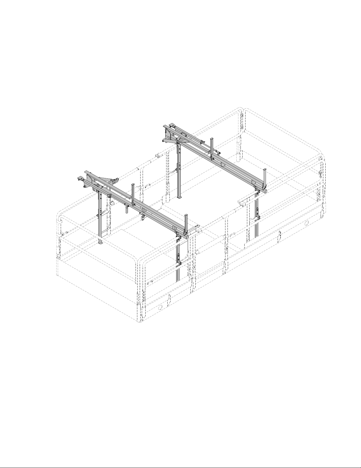
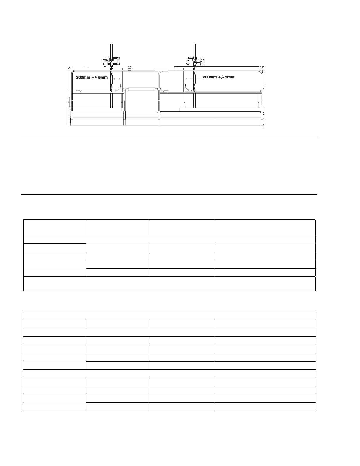
Figure 1. Easi-Cladder™ Dimensions
The Cladding device is designed to position panels weighing up to 100 kg
(220 lbs.). The main components are two frames installed on the scissor
deck. The frames are supporting the weight of the panels and transfer all
vertical forces directly to the machine’s deck. The frames are stabil ized by
C-shaped brackets attaching them to the vertical posts of the platforms’
handrail system.
SPECIFICATION
Table 1. - Platform: Ratings
3394RT
(with Dual Extension Deck)
Max. Capacity
Persons 22 2
Wind 12.5 m/s 12.5 m/s 12.5 m/s
Outriggers Required Required Required
Max. Platform Capacity * 905kg - 135kg = 770kg 565kg - 135kg = 430kg 680kg - 135kg = 545kg
* Derated 135kg (297 lb.) due to weight of cladding accessory mounted on platform deck.
Table 2. - Cladding Device Specifications
Requirement/Function 3394RT 4394RT 500RTS
Panel
Max. Panel Length 8m 8m 8m
Max. Panel Width 1.25m 1.25m 1.25m
Lifting Weight 100kg 100kg 100kg
Storage Weight 340kg 340kg 340kg
Hydraulic Power Requirements
Pressure 1000psi 1000psi 1000psi
Flow 2gpm 2gpm 2gpm
Control Functions T ether Control Box T ether Control Box T ether Control Box
Deck Extension Dual Dual Dual, Power ed
(with Dual Extension Deck)
4394RT
500RTS
(with Mega Deck)
2 – JLG Accessory Manual – 3128112
Page 11
SAFETY PRECAUTIONS
EASI-CLADDER™
General
READ AND UNDERSTAND THE OPERATORS MANUAL FOR THE SPECIFIC JLG
MODEL BEING USED. MAKE SURE LOAD IS SECURED.
DO NOT OVERLOAD CLADDING DEVICE OR PLATFORM.
DE-RATE THE PLATFORM CAPACITY BY 136 KG (300 LBS). REFER TO DECAL ON
CLADDER.
•Do not exit platform over rails or stand on rails.
•Only us e th is option on models specified.
•Keep lanyard attached at all times.
•Do not us e to handle or install glass.
•Make sure no personnel are beneath or around platform.
PREPARATION AND INSPECTION
1. Check for cracked welds and damage to cladding device.
2. Make sure cladding device is properly secured to platform.
3. Check operation of cladding device.
4. Keep Easi-Cladder control pendant and machine control box at the
same locations to allow access to E-stop when using clad ding device
controls.
3128112 – JLG Accessory Manual – 3
Page 12

EASI-CLADDER™
OPERATION
The panel (or panels) is loaded on the cladding device using a telescoping
material handler or forklift. Ample space is provided between top of the
handrail and the bottom su rface of the panels (resting on the cladding
device’s frame) to retract the forks. During driving or scissor lift operation,
panels are protected from shifting by four retractable stops.
The panels are moved manually from storage position onto the installing
arms. The installing arms are ac tuated by hydraulic cylind ers con trolled f orm
a tether mounted control box.
Pivoting telescopic supports are mounted to the cladding device’s frame.
The supports pivot to compensate for vertical misalignment between the
machine and previously installed panels. At the end of the telescoping support, two plastic plates are installed forming a “paw” that rests on the top of
the previously installed panel. The vertical surface is resting against this
panel.
The telescoping supports have built in springs that help to maintain contact
between the cladding device and the previously installed panel. Telescoping
supports are guides for panel being installed and protect it from falling
between the machine and the wall.
After telescoping supports are deployed, the installed panel is shifted to the
very end of the telescoping support with its bottom edge just over the previously installed panel and then lifted by using the installing arms.
SERVICE AND MAINTENANCE
NOTE: To shut down the cladding device depress the platform control box
Emergency stop button.
Check and tighten bolts and nut according to JLG’s torque chart.
Replace leaki ng or damaged cy linders, wo rn pads, weak or damaged
springs, and/or worn or missing decals.
4 – JLG Accessory Manual – 3128112
Page 13

EASI-CLADDER™
This page left blank intentionally.
3128112 – JLG Accessory Manual – 5
Page 14
EASI-CLADDER™
PARTS
6 – JLG Accessory Manual – 3128112
Figure 2. Easi-Cladder™ Parts Drawing
Page 15
EASI-CLADDER™
FIG & ITEM # PAR T NUMBER DESCRIPTION QTY. REV.
Figure 2. 0272439 EASI-CLADDER™ INSTALLATION Ref. B
1 0100011 Loctite #242 (Not Shown) A/R
2 0272378 Cladder Assy - Left (Note: See Items 101-135 for Breakdown) 1
3 0272379 Cladder Assy -Right (Note: See Items 101-143 for Breakdown) 1
4 0700819 Bolt, 8mm x 55mm 24
5 0700821 Bolt, 8mm x 65mm 4
6 0701022 Bolt, 10mm x 70mm 4
7 3290801 Nut, M8 x 1.25 mm 28
8 3291001 Nut, M10 x 1.5 mm 4
9 4811902 Washer, 8mm 16
10 4846643 Leg 4
11 4846648 Leg Mount 4
12 4846672 Bracket 8
EASI-CLADDER™ ASSEMBLY Ref.
0272378 Cladder Assembly - Left Side (Shown) Ref. B
0272379 Cladder Assembly - Right Side Ref. B
101 0100011 Loctite #242 ( Not Shown) A/R
102 0100081 Loctite #454 ( Not Shown) A/R
103 0630516 Screw, Shoulder 1
104 0700614 Bolt, 6mm x 30mm 1
105 0700808 Bolt, 8mm x 16mm 4
106 0700814 Bolt, 8mm x 30mm 1
107 0700821 Bolt, 8mm x 65mm 2
108 0962173 Bushing 4
109 1120556 Cap 1
110 1120557 Cap 1
111 1684236 Cylinder, Cladder 1
0962173 Bushing 4
112 2560088 Handle 1
113 3290601 Nut, M6 1
114 3290801 Nut, M8 3
115 3291201 Nut, M12 1
116 3340950 Pad, Top 1
117 3340951 Pad, Front 1
118 3340952 Pad, Storage 1
119 3340953 Pad, Tilt Plate 1
120 3422369 Pin, Plunger 3
121 3422977 Pin, Pivot 1
122 3422994 Pin, Handle Mount 1
123 3841143 Keeper 1
124 3900269 Shoulder Bolt.5mm x 1 2
125 3900327 Bolt, Shoulder 2
126 4160198 Spring 3
127 4812102 Washer, 12mm 1
128 4846640 Arm, Tilt 1
129 4846644 Support, Main 1
3128112 – JLG Accessory Manual – 7
Page 16
EASI-CLADDER™
FIG & ITEM # PART NUMBER DESCRIPTION QTY. REV.
130 Arm, Pivot Options: 1
4846645 LH 1
4846662 RH 1
131 4846646 Finger Guard 1
132 4846647 Arm 1
133 4846654 Handle 1
134 4846668 Stop 2
135 4420051 Safety, Tape 5
136 to 139 Not Used
140 1120555 Cap (Right Side Cladder Only) 2
141 1320059 Clamp (Right Side Cladder Only) 2
142 Not Available Nameplate - Serial Number (Not Shown - Located on Item 29) 1
143 3460334 Tube, PVC (Right Side Cladder Only) 1
0272477
201 0641506 Bolt 5/16"-18NC x 3/4" 2
202 0861560 Box, Junction 1 A
3641479 Rail 1
3990010 Diode 6 Amp 2
4460601 Block,Terminal 7
4460603 Bussbar, 10 Position 1
4460607 Stop, Terminal 2
4460629 Marker, Terminal 1
4460968 Connector, Strain Relief 2
202A 4460464 Pin, Male 3
4460989 Receptacle, Female - 3 Position 1
202B 4922797 Harness, Wiring 1 1/A
4460880 Connector, DIN 4
203 0861565 Pendant Control Box Assembly 1 A
4360532 Switch 1
203A 4460539 Plug, Male - 3 Position 1
4460465 Terminal 3
204 3310805 Locknut #8-32NC 4
205 3311605 Locknut 3/8"-16NC 10
206 3900316 Screw, Button 3/8"-16NC x 1" 10
207 3930816 Capscrew #8-32NC x 1" 4
208 4240127 Tie-Strap (Not Shown) A/R
209 4641249 Control Valve Assembly 1
210 4711500 Flatwasher 5/16" Narrow 2
211 4846674 Bracket 1
212 4846675 Bracket, Coupler 2
EASI-CLADDER™ BOX PENDANT & VALVE INSTALLATION
(500RTS)
Ref. B
0272586
301 0610157 PC Board (Prior to S/N 112230 Only) 1
302 0641410 Bolt 1/4"-20NC x 1 1/4" 2
303 0641506 Bolt 5/16"-18NC x 3/4" 2
EASI-CLADDER™ BOX PENDANT & VALVE INSTALLATION
(3394RT & 4394RT)
Ref. B
8 – JLG Accessory Manual – 3128112
Page 17
EASI-CLADDER™
FIG & ITEM # PAR T NUMBER DESCRIPTION QTY. REV.
304 0861492 Box, Circuit Card (Prior to S/N 112230 Only) 1 A
305 Not Used
306 3311405 Locknut 1/4"-20NC 2
307 3311605 Locknut 3/8"-16NC 7
308 3900316 Screw, Button 3/8"-16NC x 1" 7
309
310 4641249 Control Valve Assembly 1
311 4711400 Flatwasher 1/4" Narrow 2
312 4711500 Flatwasher 5/16" Narrow 2
313 4846674 Bracket 1
314 4846675 Bracket, Coupler 2
315 4922812 Harness, Wiring 1 3/C
316 1600348 Module (S/N 112230 to Present Only) 1
317 0861565 Pendant Control Box Assembly (S/N 112230 to Present Only) 1 A
317A 4460539 Plug, Male - 3 Position 1
4360533
4460880 Connector, DIN 3
4460930 Plug, Male - 8 Position 1
4460465 Socket, Female 15
4460909 Plug - 12 Position (Black) 1
4460908 Plug - 12 Position (Gray) 1
4460928 Socket, Female 11
4460761 Receptacle, Female - 4 Position 1
4460267 Pin, Male 4
4460851 Plug, Male - 8 Position 1
4460852 Connector - 8 Position Bussbar Jumper 1
4460536 Receptacle, Female - 3 Position (S/N 112230 to Present Only) 1
4460464 Pin, Male (S/N 112230 to Present Only) 3
0840058 Boot (S/N 112230 to Present Only) 1
4360532 Switch 1
4460465 Terminal 3
Pendant Control Box As sem bly (In cl ude s Elec tri cal Cab le) (Prio r
to S/N 112230 Only)
1
0272531 EASI-CLADDER™ CABLE INST ALLATION (500RTS ONLY) Ref. 1
401 1060330 Cable, Electrical - 16/3 110ft
4460043 Ring, Terminal 1
3990010 Diode, 6 Amp 2
0272528 DECAL INSTALLATION Ref. B
501 1705462 Decal, Easi-Cladder™ Capacity 4
502 1705532 Decal, Easi-Cladder™ 4
EASI-CLADDER™ KITS Ref.
Not Available 3394RT/4394RT Ref.
0272436 500RTS Ref. 1
3128112 – JLG Accessory Manual – 9
Page 18

EASI-CLADDER™
HYDRAULIC DIAGRAM
Figure 3. Easi-Cladder Hydraulic Diagram
10 – JLG Accessory Manual – 3128112
Page 19

EASI-CLADDER™
FIG & ITEM # PAR T NUMBER DESCRIPTION QTY. REV.
Figure 3. EASI-CLADDER HYDRAULIC DIAGRAM Ref.
2792577 500RTS Ref. 1
1 2220466 Fitting, 90° 5
2 2753853 Hose 4
3 2220428 Fitting, Quick Connect Male 4
4 2220427 Fitting, Quick Connect Female 4
5 2221142 Fitting 4
6 2753849 Hose 2
7 2753420 Hose 4
8 2220510 Fitting, Straight 2
9 2753852 Hose 2
10 2220237 Plug 2
11 2220415 Fitting, Straight 2
12 2220940 Fitting, 90° 1
13 2220472 Fitting, 90° 3
14 2220819 Fitting, 90° 1
15 2220609 Fitting, Straight 1
2792585 3394RT & 4394RT Ref. 1/A
101 2220466 Fitting, 90° 5
102 2753853 Hose 4
103 2220428 Fitting, Quick Connect Male 4
104 2220427 Fitting, Quick Connect Female 4
105 2221142 Fitting 4
106 2753849 Hose 2
107 2753420 Hose 2
108 2170706 Fitting, Tee 2
109 2753852 Hose 2
110 2220237 Plug 2
111 2220415 Fitting, Straight 2
112 2220940 Fitting, 90° 1
113 2130606 Fitting, 90° 3
114 2171006 Fitting, Plug 2
115 2220237 Plug 2
3128112 – JLG Accessory Manual – 11
Page 20

EASI-CLADDER™
ELECTRICAL DIAGRAM
1870156_B
Figure 4. Easi-Cladder Electrical Diagram
12 – JLG Accessory Manual – 3128112
Page 21

EASI-CLADDER™ PLUS
Rough Terrain Scissor - Cladding Panel Installer
PRODUCT USE
This product is available for use on the following JLG products
3394RT
(when equipped with 7.25m Deck with
Dual Extension Decks Only)
3128112 – JLG Accessory Manual – 13
(when equipped with Mega Deck or
Dual Extension Decks Only)
500RTS
Page 22

EASI-CLADDER™ PLUS
DESCRIPTION
SPECIFICATION
The cladding accessory when mounted to a scissor lift, is designed to lift
and position insulated wall panels for attachment to a structure on the construction site. The main components are two panel loading frames with telescoping/lifting panel handling arms installed on the scissor d eck. The
frames are bolted to the scissor lift deck and are stabilized by C-shaped
brackets attaching them to the vertical posts of the scissor lift platforms’
handrail system.
The cladding accessory can be removed f r om the scissor lift deck when not
required on the job site. All electrical, hydraulic, and vacuum lines to the
cladding accessory are attached un der the scissor deck usin g quick couplers for easy disconnect.
Table 3. - Platform: Ratings
3394RT
(7.25m - Dual Extension Decks Only)
Max. Capacit y
Persons 2 2 2
Wind 12.5 m/s 12.5 m/s 12.5 m/s
Outriggers Required Required Required
Max. Platform
Capacity *
* Derated 385kg (850l b.) due to weight of cladding accessory mounted on platform deck.
Requirement/Function
Cladding Panel
Max. Panel Length 8m 8m 8m
Max. Panel Width 1.30m 1.30m 1.30m
Maximum Panel Weight 250kg 125kg 250kg
Max. Surface Irregularity
(for vacuum to hold)
905kg - 385kg = 520kg 680kg - 385kg = 295kg 900kg - 385kg = 515kg
Table 4. - Cladding Accessory Specifications
3394RT
(7.25m - Dual Extension Decks)
Panel must be smooth and free of high ridges in the area where the vacuum cups attach to
the panel surface. The GREEN vacuum indicator light on the control box must be lit before
panel can be lifted upright 9 0° for installation.
500RTS
(with MegaDeck Only)
500RTS
(with MegaDeck)
500RTS
(with Dual Extension Decks Only)
500RTS
(with Dual Extension Decks)
Hydraulic Power Requirements
Pressure 3000psi 3000psi 3000psi
Flow 2gpm 2gpm 2gpm
Control Functions T ether Control Box T ether Control Box T ether Control Box
Deck Extension Dual, Powered Dual, Powered Dual, Powered
Electric Power Requirements for V acuum Pump
Vacuum Pump 110 volt - 50Hz - 1 Phase - Minimum Vacuum Required 24.0 –in. Hg
Onboard Electric
Generator
110 volt -
2800 Watt (Continuous)
110 volt -
2500 Watt (Continuous)
14 – JLG Accessory Manual – 3128112
Page 23

SAFETY PRECAUTIONS
EASI-CLADDER™ PLUS
General
READ AND UNDERSTAND THE OPERATORS MANUAL FOR THE SPECIFIC JLG
MODEL BEING USED. MAKE SURE LOAD IS SECURED.
DO NOT OVERLOAD CLADDING ACCESSORY OR PLATFORM.
DE-RATE THE PLATFORM CAPACITY BY 385 KG (850 LBS). REFER TO DECAL ON
CLADDER.
•Do not exit platform over rails or stand on rails.
•Use this option ONLY on models and decks specified.
•Do not use on damaged, excessively dirty or ice/snow covered pan-
els.
•Keep fall protection lanyard attached at all times.
•Keep away from moving parts of Easi-Cladder™ Plus.
•Do not use to handle or install glass.
•Keep ground personnel at least 6m from machine.
PREPARATION AND INSPECTION
1. Check for cracked welds and damage to cladding accessory.
2. Make sure cladding accessory is properly secured to platform.
3. Check operation of cladding accessory .
4. Check that the vacuum cups are clean, free of debris and there are no
torn, leaking or missing cups.
5. Keep Easi-Cladder™ Plus control box and machine control box at the
same locations to allow access to Emergency-Stop when using cladding accessory control s.
3128112 – JLG Accessory Manual – 15
Page 24

EASI-CLADDER™ PLUS
9
5
4
COMPONENT OVERVIEW
2
1
6
3
1. Control Box 6. Manua l Side to Side - Panel Movement Hand le
2. Panel Loading Rails 7. Platfor m Stabilizer P ad
3. Load Rail Stop (Outbo ard) 8. Vacuum Release Valve
4. Load Rail Stop (Inboa rd) 9. Load Rail T rolley (Op tion)
5. T elescoping/Lift Arm (w/Vacuum Manifold)
Note: Easi-Cladder™ Plus components are same for both left and right side assemblies mounted to the platform, except for
the vacuum release valve which is mounte d only on the right side and controls both the left and right side vacuum
manifolds.
Figure 5. Easi Cladder™ Plus - Component Overview
8
7
16 – JLG Accessory Manual – 3128112
Page 25

OPERATION
EASI-CLADDER™ PLUS
Power-Up and Positioning Machine
1. Power-up scissor lift.
2. Position lift in front of and parallel of work area, within 60 to 120cm (10
to 20 in.) of wall.
3. Set the outriggers and level machine.
4. Turn on the onboard power generator.
Loading Wall Panel
5. Lift and rotate the (outboard) load rail stop out of the way. (Figure 7.,
Item 2)
6. Load a wall panel onto the panel loading rails. (See Figure 7.)
NOTE: Extend the platform extension en ds to a cc om modate wall panel length,
if necessary.
7. Raise the platform to the desired height to install the panel.
8. Extend and set the platform stabilizer pads out from the side of the
machine platform against the previously installed panel.
(See Figure 8.)
NOTE: This will limit platform side to side movement once the wall panel is
lifted out over the side of the platform.
9. Move the loaded wall panel over to the (vacuum) telescoping/lift arm
side of the loading rails. (See Figure 7.)
NOTE: If machine is equipped with the optional load rail trolley, release the
trolley latch on e ach lo ad r ail and roll the panel across the loa din g ra ils .
10. Lift and rotate the (inboard) load rai l stop down ou t of the way on the
wall side of the machine. (See Figure 8.)
Lifting and Setting Wall Panel
11. Push the VACUUM ON switch, on the control box, to start the vacuum
pump. (See Figure 6., Item 3)
NOTE: The vacuum pump is rated for continuous operation. Once turned on
the pump will not shut off until the machine is powered down.
12. Using the control box, fully extend the lift arms (Figure 6., Item 6) then
raise the arms (Figure 6., Item 4) until the vacuum cups make contact
and lift the panel clear of the loading rails.
(See Figure 8.)
13. When the proper vacuum is achieved in the vacuum cups, the GREEN
indicator light on the Easi-Cladder™ Plus control box will be illuminated. (See Figure 6., Item 2)
NOTE: If proper vacuum is not achieved, th e GREEN indi cator l ight wil l not ill u-
minate and the lift function of the telescoping/lift arm will be cut out.
Lower panel and reposition lift arm. See Table 4 about panel maximum
surface irregularity.
3128112 – JLG Accessory Manual – 17
Page 26

EASI-CLADDER™ PLUS
14. Once the GREEN indicator light is lit on the control box, use the control box switches (Figure 6., Items 4 and 5) to lift the panel up 90°, tele-
scope out and lower into position. (See Figure 9.)
•Adjust panel up/down and in/out movement using the control box
switches.
•Adjust panel end to end movement, if necessary, using the manual
positioning handles located on each of the (vacuum) lift arms.
IN CASE OF VACUUM FAILURE DURING PANEL LIFT, THE VACUUM (GREEN) INDICATOR LIGHT WILL GO OFF. TELESCOPE OUT AND ROTATE UP FUNCTIONS WILL BE
DISABLED. THE OPERATOR SHOULD IMMEDIATELY LIFT DOWN AND TELESCOPE
PANEL BACK ONTO THE LOAD RAILS AND ATTEMPT TO VACUUM LOCK THE
PANEL AGAIN, OR IF NECESSARY, MAKE REPAIRS TO THE MACHINERY BEFORE
RESUMING WORK.
Releasing Panel
15. Secure panel to the wall, before releasing panel.
16. Release the vacuum lift arm by;
•Pulling the handle on the vacuum release valve, mounted above the
vacuum pump on railing.
•Then lift and pull the vacuum release switch back (Figure 6., Item 3)
and push the telescoping/lift arm retract switch (Figure 6., Item 4) on
the control box simultaneously. If arms are not retracted away from
the panel once vacuum is released, vacuum will build up and hold
onto panel again.
17. Once lift arms are retracted, manually retract the platform stabilizer
pads away from the wall.
18. To install the next wall panel repeat steps 5 thru 16, except for step 10,
vacuum pump will run continuous until machine is powered down.
NOTE: To shut down the cladding accessory depress the platform control box
Emergency stop button.
18 – JLG Accessory Manual – 3128112
Page 27

EASI-CLADDER™ PLUS
Wall Panel Removal From An Existing Wall
1. Follow machine power up steps 1 through 4.
NOTE: Extend the platform extension en ds to a cc om modate wall panel length,
if necessary.
2. Position and raise the platform to the desired height to remove the
panel.
3. Extend and set the platform stabilizer pads out from the side of the
machine platform against the panel below the one being removed.
(See Figure 8.)
NOTE: This will limit platform side to side movement once the wall panel is
lifted over the side of the platform.
4. Push the VACUUM ON switch, on the control box, to start the vacuum
pump. (See Figure 6., Item 3)
NOTE: The vacuum pump is rated for continuous operation. Once turned on
the pump will not shut off until the machine is powered down.
5. Lift and pull the vacuum release switch back (Figure 6., Item 3) while
raising the lift arm to vertical (Figure 6., Item 4).
6. Fully retract the lift arm. (Figure 6., Item 6)
STORAGE
7. Telescope the lift arm out against the p anel until the suction cu ps make
contact with the panel. The GREEN light will be on when a proper vacuum is achieved in the system.
8. Once vacuum is achieved, unscrew panel fro m the wa ll.
9. Lift panel with control box switch (Figure 6., Item 6), then telescope in
(Figure 6., Item 5), a nd lift panel d own (Figure 6., Item 4) onto panel
load rails.
10. To release the panel, follow steps 15 through 17 in "Releasing Panel"
shown in previous sub-section.
KEEP THE VACUUM MANIFOLD CUPS COVERED WHEN MACHINE IS NOT IN USE.
3128112 – JLG Accessory Manual – 19
Page 28

EASI-CLADDER™ PLUS
2
4
1
5
3
6
1. Telescope and Lift Cylinder Selection - Override
Switch - Used simultaneously with either the Telescope
Switch (item 5) and Manifold Movement Switch (item 6)
allows the Left and Right Lift Arms to be telescoped in
and out, or up and down, individually. Compensates for
machine not being parallel or level with the installation
wall.
2. Vacuum Indicator Light (GREEN) - When lit indicates
proper vacuum has been reached in the vacuum manifolds and is strong enough to hold the wall panel onto
the vacuum cups.
3. Vacuum On and Release Switch - Press FORWARD to
turn accessory and vacuum pump on.
Lift UP and pull BACK to release panel, used simultaneously with the manual vacuum release valve.
Figure 6. Easi-Cladder™ Plus Control Bo x.
4. Lift Arm Rotate Switch - Rotates the Lift Arm assembly
between horizontal and vertical positions.
5. Lift Arm Telescope Switch - Telescopes the Lift Arm
out and back in from the platfor m.
6. Vacuum Manifold Movement Switch - Moves the vac-
uum manifold in/out when horizontal or up/down when
vertical on the Lift Arm.
20 – JLG Accessory Manual – 3128112
Page 29

EASI-CLADDER™ PLUS
1
3
4
3
2
1
1. Extend Platform Extension Ends to Accommodate P anel Length 3. Panel Load Position on Load Rails
2. Lower (Outboard) Load Rail Stops when Loading Panel 4. Panel Lift Position on Load Rails
Figure 7. Panel Load ing and Lifting Position.
2
1. Stabilizer Pad Se t Against Wall 3. Lift and Rotate Load Rail Stop s Out of the Way
2. Position and Raise Lift Arm to Lock on to Panel
Figure 8. Setting Platform Stabilizer Pad, Positioning Lift Arm to Lock on to Panel.
3128112 – JLG Accessory Manual – 21
Page 30

EASI-CLADDER™ PLUS
124
3
1. Rotate Lift Arm 90° 3. Move Manifold to Raise and Lower Panel (a)
2. T elescope Arm Out (a) 4. Side to Side - P anel Movement Handles (One on Both Ends )
Note: (a) T elescope Out and Manifold Raise and Lower controls for both Lift Arms can be moved separately instead of in
tandem by using the T elescope/Lift Cylinder - Override Selection Switch (Figure 6., Item 1).
Figure 9. Panel Loading and Lifting Position.
22 – JLG Accessory Manual – 3128112
Page 31

SERVICE AND MAINTENANCE
INSTALLATION
EASI-CLADDER™ PLUS
Check and tighten bolts and nut according to JLG’s torque chart.
Replace leaking or damaged cylinders, worn pads, and worn or missing
decals.
Check vacuum manifold cups before each use, keep clean and free of
debris.
Due to various environmental operating conditions and care, replacement
interval of the vacuum manifold cups will vary. Replace the cups if they
exhibit any of the following sympt oms - become discol ored with age, are
dried out or show si gn s of cracking.
The cladder accessory is fastened to the scissor deck using pre-existing
holes drilled into the deck when accessory is ordered with the machine from
the factory . Refer to Figure 11. and detai led parts list for furth er installation of
hardware.
160mm
(6.25 in.)
Figure 10. Panel Load Rail Locating Dimension (Typical).
160mm
(6.25 in.)
3128112 – JLG Accessory Manual – 23
Page 32

EASI-CLADDER™ PLUS
PARTS
Figure 11. Easi-Cladder™ Plus Base Installation Parts Drawing
24 – JLG Accessory Manual – 3128112
Page 33

EASI-CLADDER™ PLUS
FIG & ITEM # PAR T NUMBER DESCRIPTION QTY. REV.
Figure 11. 0273304 EASI-CLADDER PLUS™ BASE INSTALLATION Ref. 1
0272962 Cladder Sub-Assembly Ref. D
1 0100081 Loctite #454 (Not Shown) A/R
2 0272962 Cladder Assembly (See Figure 2-8 for Breakdown) 2
3 0641506 Bolt 5/16"-18NC x 3/4" 8
4 0641508 Bolt 5/16"-18NC x 1" 12
5 0641510 Bolt 5/16"-18NC x 1 1/4" 12
6 0641518 Bolt 5/16"-18NC x 2 1/4" 38
7 0641528 Bolt 5/16"-18NC x 3 1/2" 8
8 1120555 Cap, Manual Storage (Prior to S/N 116736) 2
9 2560088 Handle 4
10 3311505 Locknut 5/16"-18NC 66
11 3340969 Pad, Slide 4
12 Pad, Panel Options: 2
3340970 Prior to S/N 115825
3340983 S/N 115825 to Present
13 3340971 Pad, Storage 2
14 3422369 Pin, Plunger (Prior to S/N 115825) 4
15 3460334 Tube, Manual Storage (Prior to S/N 116736) 1
16 3574325 Plate, Tooth 2
17 3900190 Bolt, Shoulder 2
18 3900289 Bolt, Shoulder 8
19 4711500 Flatwasher 5/16" Narrow 50
20 4761500 Lockwasher 5/16" 8
21 Stop, Rotating Options: 4
4846668 Prior to S/N 115825
4848837 S/N 115825 to Present
22 4846872 Bracket 2
23 4846828 Leg (Front) 2
24 4846829 Bracket 2
25 4846832 Handrail 2
26 4846835 Stand, Storage 2
27 4846836 Leg 2
28 4846837 Handle 2
29 4846838 Mount, Stabilizer 2
30 4846839 Tube, Rachet 2
31 4846840 Handle 1
32 4846841 Leg 1
33 1320059 Clamp (Prior to S/N 116736) 2
34 to 36 Not Used
37 3574631 Plate, Pad Mount (S/N 115825 to Present) 2
38 Not Used
39 4846947 Leg, Vacuum Pump Mount (S/N 115825 to Present) 1
40 4891600 Flatwasher 3/8" (S/N 115825 to Present) 2
41 4891800 Flatwasher 1/2" (S/N 115825 to Present) 4
3128112 – JLG Accessory Manual – 25
Page 34

EASI-CLADDER™ PLUS
FIG & ITEM # PART NUMBER DESCRIPTION QTY. REV.
0272961 TROLLEY ASSEMBLY Ref. B
101 0100081 Loctite #454 (Not Shown) A/R
102 33217 01 Nut 7/16"- NF 8
103 3340972 Pad 2
104 0641612 Bolt 3/8"-16NC x 1 1/2" 2
105 4711700 Flatwasher 7/16" Narrow 4
106 APL-P117 Cap, Roller 8
107 BB6-CF-1-S Follower, Cam 8
108 2940152 Latch 2
109 3311605 Locknut 3/8"-16NC 2
1 10 3574495 Plate, Retainer 4
111 4160206 Spring 2
112 4420077 Tape, Hazard 5ft/1.5m
113 4846885 Trolley 2
26 – JLG Accessory Manual – 3128112
Page 35

EASI-CLADDER™ PLUS
FIG & ITEM # PAR T NUMBER DESCRIPTION QTY. REV.
3128112 – JLG Accessory Manual – 27
Page 36

EASI-CLADDER™ PLUS
PARTS
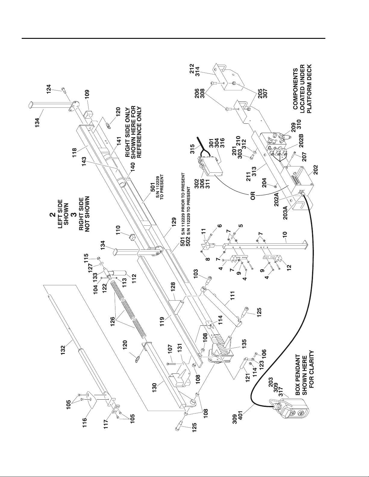
Figure 12. Easi-Cladder™ Plus Assembly Parts Drawing
28 – JLG Accessory Manual – 3128112
Page 37

EASI-CLADDER™ PLUS
FIG & ITEM # PAR T NUMBER DESCRIPTION QTY. REV.
Figure 12. 0272957 CLADDER ASSEMBLY Ref. D
1 0641405 Bolt 1/4"-20NC x 5/8" 4
2 0641509 Bolt 5/16"-18NC x 1 1/8" 3
3 0641524 Bolt 5/16"-18NC x 3" 2
4 0641604 Bolt 3/8"-16NC x 1/2" 4
5 0641605 Bolt 3/8"-16NC x 5/8" 4
6 0641606 Bolt 3/8"-16NC x 3/4" 6
7 0641812 Bolt 1/2"-13NC x 1 1/2" 2
8 0641816 Bolt 1/2"-13NC x 2" 2
9 0962173 Bushing 4
10 0962528 Bushing, Spacer 4
11 Cylinder, Cladder Lift Options: 1
1684236 Prior to S/N 116093
1684352 S/N 116093 to Present
12 Cylinder, Cladder Telescope Options: 1
1684272 Prior to S/N 116093
1684353 S/N 116093 to Present
13 Cylinder, Cladder Manipulator Options: 1
1684279 Prior to S/N 116093
1684354 S/N 116093 to Present
14 3311505 Locknut 5/16"-18NC 5
15 3311602 Nut, Jam 3/8"-16NC 2
16 3311805 Locknut 1/2"-13NC 4
17 3340852 Pad, Wear 7
18 3340951 Pad (Front) 2
19 3422828 Pin 1
20 3422899 Pin 1
21 3423051 Pin 1
22 3423052 Pin 1
23 3423053 Pin 1
24 3423055 Pin 1
25 3574511 Plate, Cradle 1
26 3760351 Ring, Retaining 4
27 3841143 Keeper, Pin 3
28 3860083 Roller 6
29 3900289 Bolt, Shoulder 1/2"-13NC x 1" 2
30 3900273 Bolt, Shoulder 1/2"-13NC x 2" 4
31 4070904 Shim #16 Gauge A/R
32 4071065 Shim .125 4
33 4711500 Flatwasher 5/16" Narrow 4
34 4711600 Flatwasher 3/8" Narrow 8
35 4711800 Flatwasher 1/2" Narrow 20
36 4846830 Tube, Hat 1
37 4846831 Tube, Slide 1
38 4846833 Arm, Lift 1
39 4846883 Attach, Pivot 1
3128112 – JLG Accessory Manual – 29
Page 38

EASI-CLADDER™ PLUS
PARTS
Figure 13. Easi-Cladder™ Plus Vacuum Arms Parts Drawing
30 – JLG Accessory Manual – 3128112
Page 39

EASI-CLADDER™ PLUS
FIG & ITEM # PAR T NUMBER DESCRIPTION QTY. REV.
Figure 13. 0273303 EASI-CLADDER PLUS VACUUM ARMS PARTS COMPONENTS Ref. 2
0273043 Vacuum Arms Assembly Ref. E
1 to 2 Not Used
3 0641406 Bolt 1/4"-20NC x 3/4" 4
4 0641420 Bolt 1/4"-20NC x 2 1/2" 4
5 0641514 Bolt 5/16"-18NC x 1 3/4" 8
6 0691810 Bolt 1/2"-24NF x 1 1/4"" 4
7 0721014 Screw #10-24 x 1 3/4" 2
8 0641604 Bolt 3/8"-16NC x 1/2" 2
9 1600356 Module, Controller 1
10 to 12 Not Used
13 331 10 05 Nut #10-24NC 2
14 3311405 Locknut 1/4"-20NC 4
15 3311505 Locknut 5/16"-18NC 8
16 3340973 Pad, Suction 12
1671129 Cover, V acuum Cup 2
17 3574393 Plate, Cam 2
18 3600380 Pump, Vacuum 1
19 to 20 Not Used
21 3930828 Capscrew #8-32 x 1 3/4" 4
22 0641812 Bolt 1/2"-13NC x 1 1/2"" 1
23 Not Used
24 4641277 Valve, Orifice 2
25 4641279 Valve, Manual 1
26 Not Used
27 4751000 Flatwasher #10 4
28 4751500 Flatwasher 5/16" 4
29 4846845 Reservoir, Vacuum 2
30 4891800 Flatwasher 1/2" Hardened 4
31 4922928 Relay Harness 1
32 4922934 Limit Switch Harness (S/N 115825 to Present) 2
Use 4360549 Limit Switch (1 per Harness) (was p/n 4360322) 1
4460968 Connector, Strain Relief (1 per Harness) 1
4460464 Pin, Male (2 per Harness) 2
4460897 Terminal, 2 Position Receptacle (1 per Harness) 1
33 3311805 Locknut 1/2"-13NC (S/N 115825 to Present) 1
34 3340852 Pad, Wear (S/N 115825 to Present) 1
35 3574620 Plate, Vacuum Pump Mounting (S/N 115825 to Present) 1
36 4711800 Flatwasher 1/2 (S/N 115825 to Present) 2
37 2120192 Filter, Water Separator (S/N 116736 to Present) 2
38 3380516 Panel, Cladder Valve Cover (S/N 116736 to Present) 2
39 4751400 Flatwasher 1/4" (S/N 116736 to Present) 8
40 0641414 Bolt 1/4"=20NC x 1 3/4" (S/N 116736 to Present) 4
3128112 – JLG Accessory Manual – 31
Page 40

EASI-CLADDER™ PLUS
FIG & ITEM # PART NUMBER DESCRIPTION QTY. REV.
0273216 DECALS INSTALLATION Ref. C
101 1704905 Decal - No Pressure Wash 2
102 1705730 Decal - Capacity 2
103 1705731 Decal - Centering 2
104 1705732 Decal - Inspect Vacuum Pads 2
105 1705746 Decal - Easi-Cladder Plus 2
106 4420051 Tape, Safety
107 4420077 Tape, Hazard
108 1701509 Decal, Manual (S/N 115825 to Present)
0273061 VALVE INSTALLATION Ref. C
201 0641406 Bolt 1/4"-20NC x 3/4" 6
202 to 206 Not Used
207 3311405 Locknut 1/4"-20NC 6
208 3311505 Locknut 5/16"-18NC 8
209 4641271 Valve, Easi-Cladde r Plus 1
210 Not Used
211 4711500 Flatwasher 5/16" 8
212 to 213 Not Used
214 0641516 Bolt 5/16"-18NC x 2" 4
215 1671119 Cover, Hose/Wire 2
216 4191706 Screw, Metric 6mm x 12mm 2
217 0140043 Alarm 1
218 0860520 Box, Manual Storage 1
219 4751400 Flatwasher 1/4" 12
220 0641528 Bolt 5/16"-18NC x 3 1/2" 4
8.5ft/2.6m
20ft/6.1m
1
32 – JLG Accessory Manual – 3128112
Page 41

EASI-CLADDER™ PLUS
FIG & ITEM # PAR T NUMBER DESCRIPTION QTY. REV.
3128112 – JLG Accessory Manual – 33
Page 42

EASI-CLADDER™ PLUS
PARTS
34 – JLG Accessory Manual – 3128112
Figure 14. Easi-Cladder™ Plus Mechanical Arms Parts Drawing
Page 43

EASI-CLADDER™ PLUS
FIG & ITEM # PAR T NUMBER DESCRIPTION QTY. REV.
Figure 14. 0273044 EASI-CLADDER PLUS MECHANICAL ARMS PARTS
COMPONENTS
Ref. A
1 0273002 Mechanical Arm Assembly (Left) (See Items 101-113 For
Breakdown)
2 0273007 Mechanical Arm Assembly (Right) (See Items 101-113 For
Breakdown)
3 0691810 Bolt 1/2"-24NF x 1 1/4"" 4
4 4891800 Flatwasher 12" Hardened 4
MECHANICAL ARM ASSEMBLIES Ref.
0273002 Left Arm Assembly Ref. A
0273007 Right Arm Assembly Ref A
Note: Qty shown is for one arm. Ref
101 0630179 Screw, Shoulder 1
102 0641605 Bolt 3/8"-16NC x 5/8" 6
103 0341609 Bolt 3/8"-16NC x 1 1/8" 4
104 3311601 Nut 3/8"-16NC 4
105 3340608 Pad, Wear 2
106 3340843 Pad, Wear 2
107 3340852 Pad, Wear 1
108 3340972 Pad, Trolley 2
109 3574424 Plate, Slide 1
110 3900273 Bolt, Shoulder 1/2" x 2" 1
111 4568778 Lever 1
112 4711600 Flatwasher 3/8" Narrow 7
113 Tray, Support Options: 1
4846853 Left Arm
4846854 Right Arm
1
1
0273269 DECALS INSTALLATION Ref. B
201 1705730 Decal - Capacity 2
202 1705731 Decal - Centering 2
203 1705746 Decal - Easi-Cladder Plus 2
204 4420051 Tape, Safety
205 1701509 Decal - Manual (S/N 115825 to Present) 1
206 4420877 Tape, Safety (Not Shown - Located On Tube Stop) (S/N 115825
to Present)
8.5ft/2.6m
10ft/3.0m
3128112 – JLG Accessory Manual – 35
Page 44

EASI-CLADDER™ PLUS
PARTS/HYDRAULIC DIAGRAM
36 – JLG Accessory Manual – 3128112
Figure 15. Easi-Cladder™ Plus Hydraulic Diagram Parts Drawing - 3394RT & 4394RT
Page 45

EASI-CLADDER™ PLUS
FIG & ITEM # PAR T NUMBER DESCRIPTION QTY. REV.
Figure 15. EASI-CLADDER PLUS HYDRAULIC DIAGRAM PARTS
COMPONENTS
2792602 HYDRAULIC DIAGRAM (ABOVE DECK) Ref. B
1 2220415 Fitting, Straight 8
2 2220466 Fitting, 90° 14
3 2220940 Fitting, 90° 6
4 2221034 Fitting, Tee 4
5 2752444 Hose 4
6 2752591 Hose 2
7 2752603 Hose 6
8 2752983 Hose 4
9 2752984 Hose 4
2902277 BELOW DECK PREP KIT Ref. 1
2792609 HYDRAULIC DIAGRAM (BELOW DECK) Ref. A
101 2170506 Fitting, Tee 2
102 2170706 Fitting, Tee 2
103 2230021 Fitting, Bulkhead 4
104 2753727 Hose 2
105 2753910 Hose 2
106 2753911 Hose 2
Ref.
0273061 VALVE INSTALLATION Ref. C
201 to 202 Not Used
203 0641508 Bolt 5/16"-18NC x 1" 4
204 to 208 Not Used
209 4641271 Valve Assembly 2
3128112 – JLG Accessory Manual – 37
Page 46

EASI-CLADDER™ PLUS
PARTS/HYDRAULIC DIAGRAM
38 – JLG Accessory Manual – 3128112
Figure 16. Easi-Cladder™ Plus Hydraulic Diagram Parts Drawing - 500RTS
Page 47

EASI-CLADDER™ PLUS
FIG & ITEM # PAR T NUMBER DESCRIPTION QTY. REV.
Figure 16. EASI-CLADDER PLUS HYDRAULIC DIAGRAM PARTS
COMPONENTS
2792602 HYDRAULIC DIAGRAM (ABOVE DECK) Ref. B
1 2220415 Fitting, Straight 8
2 2220466 Fitting, 90° 14
3 2220940 Fitting, 90° 6
4 2221034 Fitting, Tee 4
5 2752444 Hose 4
6 2752591 Hose 2
7 2752603 Hose 6
8 2752983 Hose 4
9 2752984 Hose 4
2902279 BELOW DECK PREP KIT Ref. 1
2792618 HYDRAULIC DIAGRAM (BELOW DECK) Ref. B
101 Not Used
102 2220472 Fitting, 90° 3
103 2220510 Fitting, Straight 2
104 2220609 Fitting, Reducer 1
105 2220819 Fitting, 90° 1
106 2230021 Fitting, Bulkhead 4
107 2753420 Hose 4
108 2752603 Hose 2
109 2221060 Fitting, Tee 2
110 2753849 Hose 2
Ref.
0273061 VALVE INSTALLATION Ref. C
201 to 202 Not Used
203 0641508 Bolt 5/16"-18NC x 1" 4
204 to 208 Not Used
209 4641271 Valve Assembly 2
3128112 – JLG Accessory Manual – 39
Page 48

EASI-CLADDER™ PLUS
PARTS/AIR SYSTEM DIAGRAM
Figure 17. Easi-Cladder™ Plus Air System Diagram Parts Drawing
40 – JLG Accessory Manual – 3128112
Page 49

EASI-CLADDER™ PLUS
FIG & ITEM # PAR T NUMBER DESCRIPTION QTY. REV.
Figure 17. EASI-CLADDER PLUS AIR SYSTEM PARTS COMPONENTS
(VACUUM ARMS ONLY)
2792603 HYDRAULIC DIAGRAM (ABOVE DECK) Ref. C
1 Fitting, Straight Options: A/R
2220347 Prior to S/N 116736 1
2220406 S/N 116736 to Present 2
2 2220406 Fitting, Straight 5
3 Fitting, Tee 1
2220681 Prior to S/N 115825
2220708 S/N 115825 to Present
4 2220696 Fitting, Reducer 1
5 2221160 Fitting, 90° 4
6 2221162 Fitting, Branch 2
7 2753914 Hose (Prior to S/N 115825) 1
8 2753915 Hose 3
9 2753916 Hose 1
10 2753917 Hose 2
11 2753918 Hose 4
12 2220578 Fitting (S/N 115825 to Present) 1
13 2220444 Fitting, Tee (S/N 116736 to Present) 2
14 2220250 Fitting, Reducer (S/N 116736 to Present) 2
15 2221159 Fitting (S/N 116736 to Present) 4
16 4360547 Switch, Vacuum (S/N 116736 to Present) 2
17 2220682 Fitting, Tee (S/N 116736 to Present) 1
18 2720517 Hose (S/N 116736 to Present) 2
Ref.
2902277 BELOW DECK PREP KIT - 3394RT & 4394RT Ref. 1
2902279 BELOW DECK PREP KIT - 500RTS Ref. 2
2792610 HYDRAULIC DIAGRAM (BELOW DECK) Ref. C
101 2220250 Fitting, Reducer (Prior to S/N 116736) 1
102 2220269 Fitting, Reducer 2
103 2220444 Fitting, Tee (Prior to S/N 116736) 1
104 2220700 Fitting, Tee 2
105 2221159 Fitting, Male Connector 2
106 2221163 Fitting, Female Bulkhead 2
107 2753913 Hose 1
3128112 – JLG Accessory Manual – 41
Page 50

EASI-CLADDER™ PLUS
PARTS
Figure 18. Easi-Cladder™ Plus Bulkhead & Vacuum Switch Diagram Parts
42 – JLG Accessory Manual – 3128112
Page 51

EASI-CLADDER™ PLUS
FIG & ITEM # PAR T NUMBER DESCRIPTION QTY. REV.
Figure 18. EASI-CLADDER PLUS BULKHEAD & VACUUM SWITCH PARTS
COMPONENTS (VACUUM ARMS ONLY)
Ref.
0273271 BULKHEAD PLA TE & VACUUM SWITCH VALVE INSTALLATION -
3394RT & 4394RT
1 3311605 Locknut 3/8"-16NC 4
2 3573854 Plate, Bulkhead 2
3 3900316 Screw 3/8"-16NC x 1" 4
4 4360547 Switch, Vacuum 1
5 4460470 Terminal, Nut (S/N 115825 to Present) 2
6 4460471 Terminal, Lockwasher (S/N 115825 to Present) 2
0273302 BULKHEAD PLA TE & VACUUM SWITCH VALVE INSTALLATION -
500RTS
101 0641526 Bolt 5/16"-18NC x 3 1/4" 2
102 0861635 Box, Junction 1
103 3310805 Locknut #8-32NC 4
104 3311605 Locknut 3/8"-16NC 7
105 3573854 Plate, Bulkhead 2
106 3900316 Screw 3/8"-16NC x 1" 7
107 3930816 Screw #8-32NC x 1" 4
108 4360547 Switch, Vacuum 1
109 4641295 Valve Assembly 1
110 4711500 Flatwasher 5/16" 4
111 4846674 Bracket 1
112 4460470 Terminal, Nut 2
113 4460471 Terminal, Lockwasher 2
114 1870171 Schematic, Electrical 1
115 3311505 Locknut 5/16"-18NC 2
Ref. C
Ref. D
3128112 – JLG Accessory Manual – 43
Page 52

EASI-CLADDER™ PLUS
PARTS/ELECTRICAL
Figure 19. Easi-Cladder™ Plus Electrical Components Parts Drawing
44 – JLG Accessory Manual – 3128112
Page 53

EASI-CLADDER™ PLUS
FIG & ITEM # PAR T NUMBER DESCRIPTION QTY. REV.
Figure 19. EASI-CLADDER PLUS ELECTRICAL PARTS COMPONENTS Ref.
0273061 ELECTRICAL MODULE AND HARNESS INSTALLATION Ref. C
1 0641406 Bolt 1/4"-20NC x 3/4" 4
2 to 5 Not Used
6 1600356 Module, Controller 1
7 3311405 Locknut 1/4"-20NC 4
8 to 11 Not Used
12 4922919 Arms Harness (Left Side) 1 C
12A 4460502 Receptacle, Female - 31 Position 1
4460466 Plug, Sealing 7
4460465 Socket, Female 24
4460473 Clamp, Terminal 1
12B 4460836 Plug, Male - 12 Position (Black) 1
4460466 Plug, Sealing 4
4460465 Socket, Female 8
0840055 Boot 1
12C 4460933 Plug, Male - 12 Position (Gray) 1
4460466 Plug, Sealing 3
4460465 Socket, Female 9
0840055 Boot 1
12D 4460934 Plug, Male - 12 Position (Green) 1
4460466 Plug, Sealing 6
4460465 Socket, Female 6
0840055 Boot 1
12E 4460935 Plug, Male - 12 Position (Brown) 1
4460466 Plug, Sealing 3
4460465 Socket, Female 9
0840055 Boot 1
12F 4460930 Plug, Male - 8 Position 1
4460466 Plug, Sealing 3
4460465 Socket, Female 5
0840058 Boot 1
12G 4460499 Connector, DIN 6
12H 4460891 Plug, Male - 2 Position 1
4460465 Socket, Female 2
12J 4460536 Receptacle, Female - 3 Position 1
4460464 Pin, Male 3
12K 0861609 Box, Control 1
1705757 Decal, Front 1
12L 2920108 Bulb, Light 1
2920141 Lamp, Indicator 1
12M 4060906 Guard, Switch 5
4360328 Switch, Toggle 4
4360555 Switch, Toggle - Leverlock 1
12N 4460071 Connector, Strain
12P 4460259 Terminal 19
4460260 Housing, Ter mi nal 19
3128112 – JLG Accessory Manual – 45
Page 54

EASI-CLADDER™ PLUS
FIG & ITEM # PART NUMBER DESCRIPTION QTY. REV.
3730001 Resistor 4
3990001 Diode 6
12Q 4460539 Plug, Male - 3 Position 1
4460464 Pin, Male 3
12R 4923019 Harness, Analyzer (S/N 115825 to Present) 1
1060698 Cable 1
4460465 Socket, Female 4
4460761 Housing 1
4460227 Pin, Male 4
13 4922920 Arms Harness (Right Side) 1 C
13A 4460501 Receptacle, Female - 31 Position 1
4460466 Plug, Sealing 12
4460464 Pin, Male 19
4460473 Clamp, Terminal 1
13B 4460836 Plug, Male - 12 Position (Black) 1
0840055 Boot 1
4460466 Plug, Sealing 8
4460465 Socket, Female 4
13C 4460933 Plug, Male - 12 Position (Gray) 1
0840055 Boot 1
4460466 Plug, Sealing 6
4460465 Socket, Female 6
13D 4460934 Plug, Male - 12 Position (Green) 1
0840055 Boot 1
4460466 Plug, Sealing 7
4460465 Socket, Female 5
3730001 Resistor 1
13E 4460935 Plug, Male - 12 Position (Brown) 1
0840055 Boot 1
4460466 Plug, Sealing 7
4460465 Socket, Female 5
13F 4460930 Plug, Male - 8 Position 1
0840058 Boot 1
4460466 Plug, Sealing 7
4460465 Socket, Female 1
13G 4460499 Connector, DIN 6
13H 4460891 Plug, Male - 2 Position 1
4460465 Socket, Female 2
0273043 ELECTRICAL MODULE AND HARNESS INSTALLATION Ref. E
101 to 102 Not Used
103 0641406 Bolt 1/4"-20NC x 3/4" 4
104 to 108 Not Used
109 1600356 Module, Controller 1
110 to 113 Not Used
114 3311405 Locknut 1/4"-20NC 4
115 to 120 Not Used
121 3930828 Capscrew #8-32 CN x 1 3/4" 4
46 – JLG Accessory Manual – 3128112
Page 55

EASI-CLADDER™ PLUS
FIG & ITEM # PAR T NUMBER DESCRIPTION QTY. REV.
122 to 130 Not Used
131 4922928 Relay Harness 1
0100009 Sealant (Not Shown) A/R
0100083 Grease, Heat Transfer (Not Shown) A/R
Cable, Electrical 12/3 Options: A/R
1060308 Prior to S/N 116736 11ft/3.4m
1060908 S/N 116736 to Present 24ft/7.4m
131A Box, Relay Mounting Options: 1
0861616 Prior to S/N 115825
0861632 S/N 115825 to Present
Relay, Vacuum Pump Options: 1
3740141 Prior to S/N 115825
3740142 S/N 115825 to Present
4750800 Flatwasher #8 Narrow 4
4460428 Connector, Strain Relief A/R
4460598 Connector, Strain Relief (S/N 115825 to Present) 1
131B 4460897 Receptacle, Female - 2 Position (Prior to S/N 115825) 1
4460464 Pin, Male (Prior to S/N 115825) 2
132 4922934 Harness, Switch, Limit 2
Use 4360549 Switch, Limit (was p/n 4360322) 2
4460968 Connector, Strain Relief 2
132A 4460897 Receptacle, Female - 2 Position 2
4460464 Pin, Male 4
2902277 BELOW DECK PREP KIT Ref. 1
4922918 Base Harness Ref. C
201 4460500 Plug, Male - 31 Position 1
4460466 Plug, Sealing 13
4460465 Socket, Female 18
202 4460503 Plug, Male - 31 Position 1
4460466 Plug, Sealing 7
4460464 Pin, Male 24
203 4460884 Plug, Male 4 Position 1
4460465 Socket, Female 4
204 4460930 Plug, Male - 8 Position 1
0840058 Boot 1
4460466 Plug, Sealing 3
4460465 Socket, Female 5
3128112 – JLG Accessory Manual – 47
Page 56

EASI-CLADDER™ PLUS
ELECTRICAL SCHEMATIC
48 – JLG Accessory Manual – 3128112
Figure 20. Easi-Cladder™ Plus Electrical Schematic
Page 57

Page 58

McConnellsburg PA. 17233-9533
JLG Worldwide Locations
Corporate Office
JLG Industries, Inc.
1 JLG Drive
USA
Phone: (717) 485-5161
Fax: (717) 485-6417
JLG Industries (Austr a l ia)
P.O. Box 5119
11 Bo lwarra Road
Port Macquarie
N.S.W. 2444
Australia
Phone: (61) 2 65 811111
Fax: (61) 2 65 810122
JLG Latino Americana Ltda.
Rua Eng. Carlos Stevenson,
80-Suite 71
13092-310 Campinas-SP
Brazil
Phone: (55) 19 3295 0407
Fax: (55) 19 3295 1025
JLG Industries (Europe)
Kilmartin Place,
Tannochside Park
Uddingston G71 5PH
Scotland
Phone: (44) 1 698 811005
Fax: (44) 1 698 811055
JLG Industries (UK)
Unit 12, Southside
Bredbury Park Industrial Estate
Bredbury
Stockport
SK6 2sP
England
Phone: (44) 870 200 7700
Fax: (44) 870 200 7711
JLG Europe B.V.
Jupiterstraat 234
2132 HJ Foofddorp
The Netherlands
Phone: (31) 23 565 5665
Fax: (31) 23 557 2493
JLG Industries (Pty) Ltd.
Unit 1, 24 Industrial Complex
Herman Street
Meadowdale
Germiston
South Africa
Phone: (27) 11 453 1334
Fax: (27) 11 453 1342
JLG Deutschland GmbH
Max Planck Strasse 21
D-27721 Ritterhude/lhlpohl
Bei Bremen
Germany
Phone: (49) 421 693 500
Fax: (49) 421 693 5035
JLG Industries (Norge AS)
Sofeimyrveien 12
N-1412 Sofienyr
Norway
Phone: (47) 6682 2000
Fax: (47) 6682 2001
Plataformas Elevadoras
JLG Iberica, S.L.
Trapadella, 2
P.I. Castellbisbal Sur
08755Castellbisbal
Spain
Phone: (34) 93 77 24700
Fax: (34) 93 77 11762
JLG Industries (Ital ia)
Via Po. 22
20010 Pregnana Milanese - MI
Italy
Phone: (39) 02 9359 5210
Fax: (39) 02 9359 5845
JLG Polska
UI. Krolewska
00-060 Warsawa
Poland
Phone: (48) 91 4320 245
Fax: (48) 91 4358 200
JLG Industries (Sweden)
Enkopingsvagen 150
Box 704
SE - 175 27 Jarfalla
Sweden
Phone: (46) 8 506 59500
Fax: (46) 8 506 59534
 Loading...