

Page 1

Service and Maintenance Manual
Model
1100S
1100SJP
P/N - 3121256
January 8, 2013
Page 2

Page 3

INTRODUCTION
SECTION A. INTRODUCTION - MAINTENANCE SAFETY PRECAUTIONS
A GENERAL
This section contains the general safety precautions
which must be observed during maintenance of the aerial
platform. It is of utmost importance that maintenance personnel pay strict attention to these warnings and precautions to avoid possible injury to themselves or others, or
damage to the equipment. A maintenance program must
be followed to ensure that the machine is safe to operate.
MODIFICATION OR ALTERATION OF AN AERIAL WORK PLATFORM
SHALL BE MADE ONLY WITH WRITTEN PERMISSION FROM THE
MANUFACTURER.
The specific precautions to be observed during maintenance are inserted at the appropriate point in the manual.
These precautions are, for the most part, those that apply
when servicing hydraulic and larger machine component
parts.
Your safety, and that of others, is the first consideration
when engaging in the maintenance of equipment. Always
be conscious of weight. Never attempt to move heavy
parts without the aid of a mechanical device. Do not allow
heavy objects to rest in an unstable position. When raising
a portion of the equipment, ensure that adequate support
is provided.
C MAINTENANCE
FAILURE TO COMPLY WITH SAFETY PRECAUTIONS LISTED IN
THIS SECTION COULD RESULT IN MACHINE DAMAGE, PERSONNEL INJURY OR DEATH AND IS A SAFETY VIOLATION.
• ENSURE REPLACEMENT PARTS OR COMPONENTS
ARE IDENTICAL OR EQUIVALENT TO ORIGINAL PARTS
OR COMPONENTS.
• NO SMOKING IS MANDATORY. NEVER REFUEL DURING ELECTRICAL STORMS. ENSURE THAT FUEL
CAP IS CLOSED AND SECURE AT ALL OTHER
TIMES.
• REMOVE ALL RINGS, WATCHES AND JEWELRY
WHEN PERFORMING ANY MAINTENANCE.
• DO NOT WEAR LONG HAIR UNRESTRAINED, OR
LOOSE-FITTING CLOTHING AND NECKTIES WHICH
ARE APT TO BECOME CAUGHT ON OR ENTANGLED
IN EQUIPMENT.
• OBSERVE AND OBEY ALL WARNINGS AND CAUTIONS ON MACHINE AND IN SERVICEMANUAL.
• KEEP OIL, GREASE, WATER, ETC. WIPED FROM
STANDING SURFACES AND HAND HOLDS.
• USE CAUTION WHEN CHECKING A HOT, PRESSURIZED COOLANT SYSTEM.
• NEVER WORK UNDER AN ELEVATED BOOM UNTIL
SINCE THE MACHINE MANUFACTURER HAS NO DIRECT CONTROL OVER THE FIELD INSPECTION AND MAINTENANCE, SAFETY
IN THIS AREA RESPONSIBILITY OF THE OWNER/OPERATOR.
B HYDRAULIC SYSTEM SAFETY
It should be noted that the machines hydraulic systems
operate at extremely high potentially dangerous pressures. Every effort should be made to relieve any system
pressure prior to disconnecting or removing any portion of
the system.
BOOM HAS BEEN SAFELY RESTRAINED FROM ANY
MOVEMENT BY BLOCKING OR OVERHEAD SLING,
OR BOOM SAFETY PROP HAS BEEN ENGAGED.
• BEFORE MAKING ADJUSTMENTS, LUBRICATING OR
PERFORMING ANY OTHER MAINTENANCE, SHUT
OFF ALL POWER CONTROLS.
• BATTERY SHOULD ALWAYS BE DISCONNECTEDDURING REPLACEMENT OF ELECTRICAL COMPONENTS.
• KEEP ALL SUPPORT EQUIPMENT AND ATTACHMENTS STOWED IN THEIR PROPER PLACE.
• USE ONLY APPROVED, NONFLAMMABLE CLEANING
SOLVENTS.
3121256 – JLG Lift – A-1
Page 4

INTRODUCTION
REVISON LOG
Original Issue - April 15, 2009
Revised - February 12, 2010
Revised - January 8, 2013
A-2 – JLG Lift – 3121256
Page 5

TABLE OF CONTENTS
SECTION NO. TITLE PAGE NO.
SECTION A - INTRODUCTION - MAINTENANCE SAFETY PRECAUTIONS
A General . . . . . . . . . . . . . . . . . . . . . . . . . . . . . . . . . . . . . . . . . . . . . . . . . . . . . . . . . . . . . . . . . . . . . .A-1
B Hydraulic System Safety . . . . . . . . . . . . . . . . . . . . . . . . . . . . . . . . . . . . . . . . . . . . . . . . . . . . . . . . . A-1
C Maintenance . . . . . . . . . . . . . . . . . . . . . . . . . . . . . . . . . . . . . . . . . . . . . . . . . . . . . . . . . . . . . . . . . . A-1
SECTION 1 - SPECIFICATIONS
1.1 Capacities . . . . . . . . . . . . . . . . . . . . . . . . . . . . . . . . . . . . . . . . . . . . . . . . . . . . . . . . . . . . . . . . . . . .1-1
1.2 Tires . . . . . . . . . . . . . . . . . . . . . . . . . . . . . . . . . . . . . . . . . . . . . . . . . . . . . . . . . . . . . . . . . . . . . . . . . 1-1
1.3 Engine Data . . . . . . . . . . . . . . . . . . . . . . . . . . . . . . . . . . . . . . . . . . . . . . . . . . . . . . . . . . . . . . . . . . .1-1
1.4 Specifications and Performance Data. . . . . . . . . . . . . . . . . . . . . . . . . . . . . . . . . . . . . . . . . . . . . . .1-1
Dimensional Data. . . . . . . . . . . . . . . . . . . . . . . . . . . . . . . . . . . . . . . . . . . . . . . . . . . . . . . . . . 1-1
Chassis. . . . . . . . . . . . . . . . . . . . . . . . . . . . . . . . . . . . . . . . . . . . . . . . . . . . . . . . . . . . . . . . . . 1-2
1.5 Torque Requirements . . . . . . . . . . . . . . . . . . . . . . . . . . . . . . . . . . . . . . . . . . . . . . . . . . . . . . . . . . . 1-2
1.6 Hydraulic Oil . . . . . . . . . . . . . . . . . . . . . . . . . . . . . . . . . . . . . . . . . . . . . . . . . . . . . . . . . . . . . . . . . . 1-3
1.7 Major Component Weights . . . . . . . . . . . . . . . . . . . . . . . . . . . . . . . . . . . . . . . . . . . . . . . . . . . . . . .1-4
1.8 Pressure Settings . . . . . . . . . . . . . . . . . . . . . . . . . . . . . . . . . . . . . . . . . . . . . . . . . . . . . . . . . . . . . .1-4
1.9 Lubrication and Operator Maintenance . . . . . . . . . . . . . . . . . . . . . . . . . . . . . . . . . . . . . . . . . . . . .1-6
SECTION 2 - GENERAL
2.1 Machine Preparation, Inspection, and Maintenance . . . . . . . . . . . . . . . . . . . . . . . . . . . . . . . . . . .2-1
General. . . . . . . . . . . . . . . . . . . . . . . . . . . . . . . . . . . . . . . . . . . . . . . . . . . . . . . . . . . . . . . . . . 2-1
Preparation, Inspection, and Maintenance . . . . . . . . . . . . . . . . . . . . . . . . . . . . . . . . . . . . . . 2-1
Pre-Start Inspection . . . . . . . . . . . . . . . . . . . . . . . . . . . . . . . . . . . . . . . . . . . . . . . . . . . . . . . . 2-1
Pre-Delivery Inspection and Frequent Inspection . . . . . . . . . . . . . . . . . . . . . . . . . . . . . . . . . 2-1
Annual Machine Inspection . . . . . . . . . . . . . . . . . . . . . . . . . . . . . . . . . . . . . . . . . . . . . . . . . . 2-1
Preventative Maintenance . . . . . . . . . . . . . . . . . . . . . . . . . . . . . . . . . . . . . . . . . . . . . . . . . . . 2-1
2.2 Service and Guidelines . . . . . . . . . . . . . . . . . . . . . . . . . . . . . . . . . . . . . . . . . . . . . . . . . . . . . . . . . .2-2
General. . . . . . . . . . . . . . . . . . . . . . . . . . . . . . . . . . . . . . . . . . . . . . . . . . . . . . . . . . . . . . . . . . 2-2
Safety and Workmanship . . . . . . . . . . . . . . . . . . . . . . . . . . . . . . . . . . . . . . . . . . . . . . . . . . . 2-2
Cleanliness. . . . . . . . . . . . . . . . . . . . . . . . . . . . . . . . . . . . . . . . . . . . . . . . . . . . . . . . . . . . . . . 2-2
Components Removal and Installation . . . . . . . . . . . . . . . . . . . . . . . . . . . . . . . . . . . . . . . . . 2-2
Component Disassembly and Reassembly . . . . . . . . . . . . . . . . . . . . . . . . . . . . . . . . . . . . . 2-3
Pressure-Fit Parts. . . . . . . . . . . . . . . . . . . . . . . . . . . . . . . . . . . . . . . . . . . . . . . . . . . . . . . . . . 2-3
Bearings . . . . . . . . . . . . . . . . . . . . . . . . . . . . . . . . . . . . . . . . . . . . . . . . . . . . . . . . . . . . . . . . . 2-3
Gaskets . . . . . . . . . . . . . . . . . . . . . . . . . . . . . . . . . . . . . . . . . . . . . . . . . . . . . . . . . . . . . . . . . 2-3
Bolt Usage and Torque Application . . . . . . . . . . . . . . . . . . . . . . . . . . . . . . . . . . . . . . . . . . . 2-3
Hydraulic Lines and Electrical Wiring . . . . . . . . . . . . . . . . . . . . . . . . . . . . . . . . . . . . . . . . . . 2-3
Hydraulic System. . . . . . . . . . . . . . . . . . . . . . . . . . . . . . . . . . . . . . . . . . . . . . . . . . . . . . . . . . 2-3
Lubrication . . . . . . . . . . . . . . . . . . . . . . . . . . . . . . . . . . . . . . . . . . . . . . . . . . . . . . . . . . . . . . . 2-3
Battery . . . . . . . . . . . . . . . . . . . . . . . . . . . . . . . . . . . . . . . . . . . . . . . . . . . . . . . . . . . . . . . . . . 2-3
Lubrication and Servicing . . . . . . . . . . . . . . . . . . . . . . . . . . . . . . . . . . . . . . . . . . . . . . . . . . . 2-3
2.3 Lubrication and Information . . . . . . . . . . . . . . . . . . . . . . . . . . . . . . . . . . . . . . . . . . . . . . . . . . . . . .2-3
Hydraulic System. . . . . . . . . . . . . . . . . . . . . . . . . . . . . . . . . . . . . . . . . . . . . . . . . . . . . . . . . . 2-3
Hydraulic Oil . . . . . . . . . . . . . . . . . . . . . . . . . . . . . . . . . . . . . . . . . . . . . . . . . . . . . . . . . . . . . 2-4
Changing Hydraulic Oil . . . . . . . . . . . . . . . . . . . . . . . . . . . . . . . . . . . . . . . . . . . . . . . . . . . . . 2-4
Lubrication Specifications . . . . . . . . . . . . . . . . . . . . . . . . . . . . . . . . . . . . . . . . . . . . . . . . . . . 2-4
2.4 Cylinder Drift Test . . . . . . . . . . . . . . . . . . . . . . . . . . . . . . . . . . . . . . . . . . . . . . . . . . . . . . . . . . . . . .2-4
Platform Drift . . . . . . . . . . . . . . . . . . . . . . . . . . . . . . . . . . . . . . . . . . . . . . . . . . . . . . . . . . . . . 2-4
Cylinder Drift . . . . . . . . . . . . . . . . . . . . . . . . . . . . . . . . . . . . . . . . . . . . . . . . . . . . . . . . . . . . . 2-5
2.5 Pins and Composite Bearing Repair Guidelines . . . . . . . . . . . . . . . . . . . . . . . . . . . . . . . . . . . . . .2-5
2.6 Welding on JLG Equipment . . . . . . . . . . . . . . . . . . . . . . . . . . . . . . . . . . . . . . . . . . . . . . . . . . . . . . 2-5
Do the Following When Welding on JLG Equipment . . . . . . . . . . . . . . . . . . . . . . . . . . . . . . 2-5
Do NOT Do the Following When Welding on JLG Equipment . . . . . . . . . . . . . . . . . . . . . . . 2-5
3121256 – JLG Lift – i
Page 6

TABLE OF CONTENTS
SECTION NO. TITLE PAGE NO.
SECTION 3 - CHASSIS & TURNTABLE
3.1 Tires & Wheels. . . . . . . . . . . . . . . . . . . . . . . . . . . . . . . . . . . . . . . . . . . . . . . . . . . . . . . . . . . . . . . . . 3-1
Tire Inflation . . . . . . . . . . . . . . . . . . . . . . . . . . . . . . . . . . . . . . . . . . . . . . . . . . . . . . . . . . . . . . 3-1
Tire Damage . . . . . . . . . . . . . . . . . . . . . . . . . . . . . . . . . . . . . . . . . . . . . . . . . . . . . . . . . . . . . 3-1
Wheel and Tire Replacement . . . . . . . . . . . . . . . . . . . . . . . . . . . . . . . . . . . . . . . . . . . . . . . . 3-1
Wheel Installation. . . . . . . . . . . . . . . . . . . . . . . . . . . . . . . . . . . . . . . . . . . . . . . . . . . . . . . . . . 3-1
3.2 Extending Axles. . . . . . . . . . . . . . . . . . . . . . . . . . . . . . . . . . . . . . . . . . . . . . . . . . . . . . . . . . . . . . . .3-2
3.3 Axle Limit Switch Adjustment Procedure . . . . . . . . . . . . . . . . . . . . . . . . . . . . . . . . . . . . . . . . . . . .3-2
3.4 Drive System (1100SJP) . . . . . . . . . . . . . . . . . . . . . . . . . . . . . . . . . . . . . . . . . . . . . . . . . . . . . . . . .3-3
3.5 Steering Control System . . . . . . . . . . . . . . . . . . . . . . . . . . . . . . . . . . . . . . . . . . . . . . . . . . . . . . . . .3-3
3.6 Drive/Steering Speed Control . . . . . . . . . . . . . . . . . . . . . . . . . . . . . . . . . . . . . . . . . . . . . . . . . . . . .3-4
3.7 Traction Control System . . . . . . . . . . . . . . . . . . . . . . . . . . . . . . . . . . . . . . . . . . . . . . . . . . . . . . . . . 3-4
3.8 Drive Orientation System . . . . . . . . . . . . . . . . . . . . . . . . . . . . . . . . . . . . . . . . . . . . . . . . . . . . . . . .3-4
3.9 Oscillating Axle System (1100SJP) . . . . . . . . . . . . . . . . . . . . . . . . . . . . . . . . . . . . . . . . . . . . . . . . .3-22
3.10 Oscillating Axle Bleeding Procedure and Lockout Test (1100SJP) . . . . . . . . . . . . . . . . . . . . . . . .3-22
Lockout Cylinder Bleeding . . . . . . . . . . . . . . . . . . . . . . . . . . . . . . . . . . . . . . . . . . . . . . . . . . 3-22
Oscillating Axle Lockout Test . . . . . . . . . . . . . . . . . . . . . . . . . . . . . . . . . . . . . . . . . . . . . . . . 3-23
3.11 Drive Hub - Reggiana Riduttori . . . . . . . . . . . . . . . . . . . . . . . . . . . . . . . . . . . . . . . . . . . . . . . . . . . .3-24
Removal . . . . . . . . . . . . . . . . . . . . . . . . . . . . . . . . . . . . . . . . . . . . . . . . . . . . . . . . . . . . . . . . . 3-24
Symbol Nomenclature. . . . . . . . . . . . . . . . . . . . . . . . . . . . . . . . . . . . . . . . . . . . . . . . . . . . . . 3-24
Tools . . . . . . . . . . . . . . . . . . . . . . . . . . . . . . . . . . . . . . . . . . . . . . . . . . . . . . . . . . . . . . . . . . . 3-25
Disassembly. . . . . . . . . . . . . . . . . . . . . . . . . . . . . . . . . . . . . . . . . . . . . . . . . . . . . . . . . . . . . . 3-30
Assembly . . . . . . . . . . . . . . . . . . . . . . . . . . . . . . . . . . . . . . . . . . . . . . . . . . . . . . . . . . . . . . . . 3-34
Installation . . . . . . . . . . . . . . . . . . . . . . . . . . . . . . . . . . . . . . . . . . . . . . . . . . . . . . . . . . . . . . . 3-38
3.12 Swing Drive . . . . . . . . . . . . . . . . . . . . . . . . . . . . . . . . . . . . . . . . . . . . . . . . . . . . . . . . . . . . . . . . . . . 3-39
Roll and Leak Testing . . . . . . . . . . . . . . . . . . . . . . . . . . . . . . . . . . . . . . . . . . . . . . . . . . . . . . 3-39
Tightening and Torquing Bolts . . . . . . . . . . . . . . . . . . . . . . . . . . . . . . . . . . . . . . . . . . . . . . . 3-39
Motor Control Valve Disassembly . . . . . . . . . . . . . . . . . . . . . . . . . . . . . . . . . . . . . . . . . . . . . 3-40
Motor and Brake Disassembly . . . . . . . . . . . . . . . . . . . . . . . . . . . . . . . . . . . . . . . . . . . . . . . 3-41
Main Disassembly . . . . . . . . . . . . . . . . . . . . . . . . . . . . . . . . . . . . . . . . . . . . . . . . . . . . . . . . . 3-42
Hub-Shaft Disassembly . . . . . . . . . . . . . . . . . . . . . . . . . . . . . . . . . . . . . . . . . . . . . . . . . . . . . 3-43
Carrier Disassembly. . . . . . . . . . . . . . . . . . . . . . . . . . . . . . . . . . . . . . . . . . . . . . . . . . . . . . . . 3-44
Hub-Shaft Sub-Assembly . . . . . . . . . . . . . . . . . . . . . . . . . . . . . . . . . . . . . . . . . . . . . . . . . . . 3-45
Carrier Sub-Assembly . . . . . . . . . . . . . . . . . . . . . . . . . . . . . . . . . . . . . . . . . . . . . . . . . . . . . . 3-46
Main Assembly. . . . . . . . . . . . . . . . . . . . . . . . . . . . . . . . . . . . . . . . . . . . . . . . . . . . . . . . . . . . 3-48
Motor and Brake Assembly . . . . . . . . . . . . . . . . . . . . . . . . . . . . . . . . . . . . . . . . . . . . . . . . . . 3-50
Motor Control Valve Assembly . . . . . . . . . . . . . . . . . . . . . . . . . . . . . . . . . . . . . . . . . . . . . . . 3-51
3.13 Swing Brake . . . . . . . . . . . . . . . . . . . . . . . . . . . . . . . . . . . . . . . . . . . . . . . . . . . . . . . . . . . . . . . . . .3-52
Pre-Installation Checks . . . . . . . . . . . . . . . . . . . . . . . . . . . . . . . . . . . . . . . . . . . . . . . . . . . . . 3-52
Installation . . . . . . . . . . . . . . . . . . . . . . . . . . . . . . . . . . . . . . . . . . . . . . . . . . . . . . . . . . . . . . . 3-53
Maintenance . . . . . . . . . . . . . . . . . . . . . . . . . . . . . . . . . . . . . . . . . . . . . . . . . . . . . . . . . . . . . 3-53
Disassembly. . . . . . . . . . . . . . . . . . . . . . . . . . . . . . . . . . . . . . . . . . . . . . . . . . . . . . . . . . . . . . 3-53
Examination . . . . . . . . . . . . . . . . . . . . . . . . . . . . . . . . . . . . . . . . . . . . . . . . . . . . . . . . . . . . . . 3-53
Assembly . . . . . . . . . . . . . . . . . . . . . . . . . . . . . . . . . . . . . . . . . . . . . . . . . . . . . . . . . . . . . . . . 3-53
3.14 Swing Motor . . . . . . . . . . . . . . . . . . . . . . . . . . . . . . . . . . . . . . . . . . . . . . . . . . . . . . . . . . . . . . . . . .3-55
Disassembly and inspection . . . . . . . . . . . . . . . . . . . . . . . . . . . . . . . . . . . . . . . . . . . . . . . . . 3-55
Assembly . . . . . . . . . . . . . . . . . . . . . . . . . . . . . . . . . . . . . . . . . . . . . . . . . . . . . . . . . . . . . . . . 3-62
One Piece Stator Construction . . . . . . . . . . . . . . . . . . . . . . . . . . . . . . . . . . . . . . . . . . . . . . . 3-69
ii – JLG Lift – 3121256
Page 7

TABLE OF CONTENTS
SECTION NO. TITLE PAGE NO.
3.15 Procedure For Setting Gear Backlash . . . . . . . . . . . . . . . . . . . . . . . . . . . . . . . . . . . . . . . . . . . . . .3-70
3.16 Swing Drive Lubrication . . . . . . . . . . . . . . . . . . . . . . . . . . . . . . . . . . . . . . . . . . . . . . . . . . . . . . . . .3-71
3.17 Swing Bearing . . . . . . . . . . . . . . . . . . . . . . . . . . . . . . . . . . . . . . . . . . . . . . . . . . . . . . . . . . . . . . . . .3-73
Turntable Bearing Mounting Bolt Condition Check . . . . . . . . . . . . . . . . . . . . . . . . . . . . . . . 3-73
Wear Tolerance . . . . . . . . . . . . . . . . . . . . . . . . . . . . . . . . . . . . . . . . . . . . . . . . . . . . . . . . . . . 3-76
Swing Bearing Removal . . . . . . . . . . . . . . . . . . . . . . . . . . . . . . . . . . . . . . . . . . . . . . . . . . . . 3-76
Swing Bearing Installation . . . . . . . . . . . . . . . . . . . . . . . . . . . . . . . . . . . . . . . . . . . . . . . . . . . 3-78
Swing Bearing Torque Values . . . . . . . . . . . . . . . . . . . . . . . . . . . . . . . . . . . . . . . . . . . . . . . . 3-79
3.18 Swing Speed Proportioning . . . . . . . . . . . . . . . . . . . . . . . . . . . . . . . . . . . . . . . . . . . . . . . . . . . . . .3-80
3.19 Chassis Tilt Indicator System . . . . . . . . . . . . . . . . . . . . . . . . . . . . . . . . . . . . . . . . . . . . . . . . . . . . .3-80
3.20 Rotary Coupling. . . . . . . . . . . . . . . . . . . . . . . . . . . . . . . . . . . . . . . . . . . . . . . . . . . . . . . . . . . . . . . .3-81
3.21 Generator (SJP Only) . . . . . . . . . . . . . . . . . . . . . . . . . . . . . . . . . . . . . . . . . . . . . . . . . . . . . . . . . . . 3-85
Every 250 hours . . . . . . . . . . . . . . . . . . . . . . . . . . . . . . . . . . . . . . . . . . . . . . . . . . . . . . . . . . . 3-85
Every 500 hours . . . . . . . . . . . . . . . . . . . . . . . . . . . . . . . . . . . . . . . . . . . . . . . . . . . . . . . . . . . 3-85
Overload Protection. . . . . . . . . . . . . . . . . . . . . . . . . . . . . . . . . . . . . . . . . . . . . . . . . . . . . . . . 3-86
Inspecting Brushes, Replacing Brushes, and Cleaning Slip Rings . . . . . . . . . . . . . . . . . . . 3-86
3.22 Auxiliary Power System. . . . . . . . . . . . . . . . . . . . . . . . . . . . . . . . . . . . . . . . . . . . . . . . . . . . . . . . . .3-88
3.23 Engine . . . . . . . . . . . . . . . . . . . . . . . . . . . . . . . . . . . . . . . . . . . . . . . . . . . . . . . . . . . . . . . . . . . . . . .3-89
Glow Plugs. . . . . . . . . . . . . . . . . . . . . . . . . . . . . . . . . . . . . . . . . . . . . . . . . . . . . . . . . . . . . . . 3-89
Checking Oil Level. . . . . . . . . . . . . . . . . . . . . . . . . . . . . . . . . . . . . . . . . . . . . . . . . . . . . . . . . 3-89
Changing Engine Oil . . . . . . . . . . . . . . . . . . . . . . . . . . . . . . . . . . . . . . . . . . . . . . . . . . . . . . . 3-89
Changing the Oil Filter . . . . . . . . . . . . . . . . . . . . . . . . . . . . . . . . . . . . . . . . . . . . . . . . . . . . . . 3-90
Replacing the Fuel Filter . . . . . . . . . . . . . . . . . . . . . . . . . . . . . . . . . . . . . . . . . . . . . . . . . . . . 3-91
Cleaning the Fuel Strainer . . . . . . . . . . . . . . . . . . . . . . . . . . . . . . . . . . . . . . . . . . . . . . . . . . . 3-91
3.24 Deutz EMR 2 . . . . . . . . . . . . . . . . . . . . . . . . . . . . . . . . . . . . . . . . . . . . . . . . . . . . . . . . . . . . . . . . . .3-92
3.25 Bio Fuel in Deutz Engines . . . . . . . . . . . . . . . . . . . . . . . . . . . . . . . . . . . . . . . . . . . . . . . . . . . . . . . .3-105
General. . . . . . . . . . . . . . . . . . . . . . . . . . . . . . . . . . . . . . . . . . . . . . . . . . . . . . . . . . . . . . . . . . 3-105
Bio Fuel . . . . . . . . . . . . . . . . . . . . . . . . . . . . . . . . . . . . . . . . . . . . . . . . . . . . . . . . . . . . . . . . . 3-105
Biological Contamination In Fuels. . . . . . . . . . . . . . . . . . . . . . . . . . . . . . . . . . . . . . . . . . . . . 3-106
SECTION 4 - BOOM & PLATFORM
4.1 Boom Systems . . . . . . . . . . . . . . . . . . . . . . . . . . . . . . . . . . . . . . . . . . . . . . . . . . . . . . . . . . . . . . . .4-1
Broken Cable Indicator System. . . . . . . . . . . . . . . . . . . . . . . . . . . . . . . . . . . . . . . . . . . . . . . 4-1
Platform Control Enable System . . . . . . . . . . . . . . . . . . . . . . . . . . . . . . . . . . . . . . . . . . . . . . 4-1
Transport Position Sensing System . . . . . . . . . . . . . . . . . . . . . . . . . . . . . . . . . . . . . . . . . . . 4-1
Beyond Transport - Drive Speed Cutback System . . . . . . . . . . . . . . . . . . . . . . . . . . . . . . . . 4-1
Jib Stow System (1100SJP Only) . . . . . . . . . . . . . . . . . . . . . . . . . . . . . . . . . . . . . . . . . . . . . 4-2
Envelope Tracking System . . . . . . . . . . . . . . . . . . . . . . . . . . . . . . . . . . . . . . . . . . . . . . . . . . 4-2
Moment Control System . . . . . . . . . . . . . . . . . . . . . . . . . . . . . . . . . . . . . . . . . . . . . . . . . . . . 4-3
Boom Control System (BCS) Functional Check (Push to Test) System . . . . . . . . . . . . . . . 4-3
Controlled Arc System. . . . . . . . . . . . . . . . . . . . . . . . . . . . . . . . . . . . . . . . . . . . . . . . . . . . . . 4-3
Controlled Boom Angle System . . . . . . . . . . . . . . . . . . . . . . . . . . . . . . . . . . . . . . . . . . . . . . 4-4
Envelope Tracking . . . . . . . . . . . . . . . . . . . . . . . . . . . . . . . . . . . . . . . . . . . . . . . . . . . . . . . . . 4-4
Slow Down System . . . . . . . . . . . . . . . . . . . . . . . . . . . . . . . . . . . . . . . . . . . . . . . . . . . . . . . . 4-4
Dual Capacity System (1100SJP Only) . . . . . . . . . . . . . . . . . . . . . . . . . . . . . . . . . . . . . . . . . 4-5
Electronic Platform Leveling . . . . . . . . . . . . . . . . . . . . . . . . . . . . . . . . . . . . . . . . . . . . . . . . . 4-5
Boom Control Select . . . . . . . . . . . . . . . . . . . . . . . . . . . . . . . . . . . . . . . . . . . . . . . . . . . . . . . 4-6
4.2 Boom Assembly . . . . . . . . . . . . . . . . . . . . . . . . . . . . . . . . . . . . . . . . . . . . . . . . . . . . . . . . . . . . . . .4-7
Removal . . . . . . . . . . . . . . . . . . . . . . . . . . . . . . . . . . . . . . . . . . . . . . . . . . . . . . . . . . . . . . . . . 4-7
Disassembly. . . . . . . . . . . . . . . . . . . . . . . . . . . . . . . . . . . . . . . . . . . . . . . . . . . . . . . . . . . . . . 4-18
Assembly . . . . . . . . . . . . . . . . . . . . . . . . . . . . . . . . . . . . . . . . . . . . . . . . . . . . . . . . . . . . . . . . 4-20
3121256 – JLG Lift – iii
Page 8

TABLE OF CONTENTS
SECTION NO. TITLE PAGE NO.
4.3 Jib Rotator Orientation (1100SJP Only) . . . . . . . . . . . . . . . . . . . . . . . . . . . . . . . . . . . . . . . . . . . . .4-31
4.4 Jib Lift End of Stroke Dampening . . . . . . . . . . . . . . . . . . . . . . . . . . . . . . . . . . . . . . . . . . . . . . . . . . 4-31
4.5 Load Sensing Pin Removal and Installation . . . . . . . . . . . . . . . . . . . . . . . . . . . . . . . . . . . . . . . . . .4-31
4.6 Powertrack Maintenance. . . . . . . . . . . . . . . . . . . . . . . . . . . . . . . . . . . . . . . . . . . . . . . . . . . . . . . . .4-41
One Piece Bracket Maintenance . . . . . . . . . . . . . . . . . . . . . . . . . . . . . . . . . . . . . . . . . . . . . . 4-41
Two Piece Bracket Maintenance . . . . . . . . . . . . . . . . . . . . . . . . . . . . . . . . . . . . . . . . . . . . . . 4-43
Snap Rings and Screws . . . . . . . . . . . . . . . . . . . . . . . . . . . . . . . . . . . . . . . . . . . . . . . . . . . . 4-44
4.7 Boom Cleanliness Guidelines . . . . . . . . . . . . . . . . . . . . . . . . . . . . . . . . . . . . . . . . . . . . . . . . . . . . . 4-52
4.8 Hose Routing Procedure. . . . . . . . . . . . . . . . . . . . . . . . . . . . . . . . . . . . . . . . . . . . . . . . . . . . . . . . .4-52
4.9 Wire Rope . . . . . . . . . . . . . . . . . . . . . . . . . . . . . . . . . . . . . . . . . . . . . . . . . . . . . . . . . . . . . . . . . . . .4-52
Inspection . . . . . . . . . . . . . . . . . . . . . . . . . . . . . . . . . . . . . . . . . . . . . . . . . . . . . . . . . . . . . . . 4-52
Three Month Inspection. . . . . . . . . . . . . . . . . . . . . . . . . . . . . . . . . . . . . . . . . . . . . . . . . . . . . 4-53
Seven Year Inspection. . . . . . . . . . . . . . . . . . . . . . . . . . . . . . . . . . . . . . . . . . . . . . . . . . . . . . 4-53
Replacement Criteria . . . . . . . . . . . . . . . . . . . . . . . . . . . . . . . . . . . . . . . . . . . . . . . . . . . . . . . 4-53
Wire Rope Tensioning Procedure . . . . . . . . . . . . . . . . . . . . . . . . . . . . . . . . . . . . . . . . . . . . . 4-54
4.10 Broken Boom Cable Proximity Switch . . . . . . . . . . . . . . . . . . . . . . . . . . . . . . . . . . . . . . . . . . . . . . 4-58
Adjusting the Proximity Switch . . . . . . . . . . . . . . . . . . . . . . . . . . . . . . . . . . . . . . . . . . . . . . . 4-58
4.11 Electronic Platform Leveling . . . . . . . . . . . . . . . . . . . . . . . . . . . . . . . . . . . . . . . . . . . . . . . . . . . . . . 4-58
Description. . . . . . . . . . . . . . . . . . . . . . . . . . . . . . . . . . . . . . . . . . . . . . . . . . . . . . . . . . . . . . . 4-58
Normal Operation . . . . . . . . . . . . . . . . . . . . . . . . . . . . . . . . . . . . . . . . . . . . . . . . . . . . . . . . . 4-59
4.12 Rotary Actuator . . . . . . . . . . . . . . . . . . . . . . . . . . . . . . . . . . . . . . . . . . . . . . . . . . . . . . . . . . . . . . . .4-60
Theory of Operation. . . . . . . . . . . . . . . . . . . . . . . . . . . . . . . . . . . . . . . . . . . . . . . . . . . . . . . . 4-60
Required Tools. . . . . . . . . . . . . . . . . . . . . . . . . . . . . . . . . . . . . . . . . . . . . . . . . . . . . . . . . . . . 4-60
Disassembly. . . . . . . . . . . . . . . . . . . . . . . . . . . . . . . . . . . . . . . . . . . . . . . . . . . . . . . . . . . . . . 4-63
Inspection . . . . . . . . . . . . . . . . . . . . . . . . . . . . . . . . . . . . . . . . . . . . . . . . . . . . . . . . . . . . . . . 4-67
Assembly . . . . . . . . . . . . . . . . . . . . . . . . . . . . . . . . . . . . . . . . . . . . . . . . . . . . . . . . . . . . . . . . 4-67
Installing Counterbalance Valve . . . . . . . . . . . . . . . . . . . . . . . . . . . . . . . . . . . . . . . . . . . . . . 4-72
Testing the Actuator. . . . . . . . . . . . . . . . . . . . . . . . . . . . . . . . . . . . . . . . . . . . . . . . . . . . . . . . 4-72
Troubleshooting. . . . . . . . . . . . . . . . . . . . . . . . . . . . . . . . . . . . . . . . . . . . . . . . . . . . . . . . . . . 4-73
Bleeding After Installation . . . . . . . . . . . . . . . . . . . . . . . . . . . . . . . . . . . . . . . . . . . . . . . . . . . 4-74
SECTION 5 - HYDRAULICS
5.1 Lubricating O-Rings in the Hydraulic System. . . . . . . . . . . . . . . . . . . . . . . . . . . . . . . . . . . . . . . . .5-1
Cup and Brush. . . . . . . . . . . . . . . . . . . . . . . . . . . . . . . . . . . . . . . . . . . . . . . . . . . . . . . . . . . . 5-1
Dip Method . . . . . . . . . . . . . . . . . . . . . . . . . . . . . . . . . . . . . . . . . . . . . . . . . . . . . . . . . . . . . . 5-2
Spray Method . . . . . . . . . . . . . . . . . . . . . . . . . . . . . . . . . . . . . . . . . . . . . . . . . . . . . . . . . . . . 5-2
Brush-on Method . . . . . . . . . . . . . . . . . . . . . . . . . . . . . . . . . . . . . . . . . . . . . . . . . . . . . . . . . . 5-2
5.2 Cylinder Repair . . . . . . . . . . . . . . . . . . . . . . . . . . . . . . . . . . . . . . . . . . . . . . . . . . . . . . . . . . . . . . . .5-3
Disassembly. . . . . . . . . . . . . . . . . . . . . . . . . . . . . . . . . . . . . . . . . . . . . . . . . . . . . . . . . . . . . . 5-3
Cleaning and Inspection . . . . . . . . . . . . . . . . . . . . . . . . . . . . . . . . . . . . . . . . . . . . . . . . . . . . 5-12
Assembly . . . . . . . . . . . . . . . . . . . . . . . . . . . . . . . . . . . . . . . . . . . . . . . . . . . . . . . . . . . . . . . . 5-14
5.3 Hydraulic Tank . . . . . . . . . . . . . . . . . . . . . . . . . . . . . . . . . . . . . . . . . . . . . . . . . . . . . . . . . . . . . . . .5-24
5.4 Pressure Setting Procedure . . . . . . . . . . . . . . . . . . . . . . . . . . . . . . . . . . . . . . . . . . . . . . . . . . . . . . 5-24
Set Up of the Function Pump . . . . . . . . . . . . . . . . . . . . . . . . . . . . . . . . . . . . . . . . . . . . . . . . 5-24
Adjustments made at the Main Valve Bank. . . . . . . . . . . . . . . . . . . . . . . . . . . . . . . . . . . . . . 5-25
Adjustments Made at the Frame Valve Bank . . . . . . . . . . . . . . . . . . . . . . . . . . . . . . . . . . . . 5-26
Adjustments Made at the Platform Valve Bank . . . . . . . . . . . . . . . . . . . . . . . . . . . . . . . . . . . 5-30
5.5 Drive Pumps . . . . . . . . . . . . . . . . . . . . . . . . . . . . . . . . . . . . . . . . . . . . . . . . . . . . . . . . . . . . . . . . . . 5-31
Troubleshooting Procedure. . . . . . . . . . . . . . . . . . . . . . . . . . . . . . . . . . . . . . . . . . . . . . . . . . 5-31
Charge Pressure Relief Valve Adjustment. . . . . . . . . . . . . . . . . . . . . . . . . . . . . . . . . . . . . . . 5-34
Mechanical Centering of Pump . . . . . . . . . . . . . . . . . . . . . . . . . . . . . . . . . . . . . . . . . . . . . . . 5-35
Hydraulic Centering of Control Modules. . . . . . . . . . . . . . . . . . . . . . . . . . . . . . . . . . . . . . . . 5-35
High Pressure Relief Valve Adjustments . . . . . . . . . . . . . . . . . . . . . . . . . . . . . . . . . . . . . . . . 5-36
Removal and inspection of charge pump . . . . . . . . . . . . . . . . . . . . . . . . . . . . . . . . . . . . . . . 5-36
Routine Maintenance. . . . . . . . . . . . . . . . . . . . . . . . . . . . . . . . . . . . . . . . . . . . . . . . . . . . . . . 5-37
Removal and Installation of Shaft Seal . . . . . . . . . . . . . . . . . . . . . . . . . . . . . . . . . . . . . . . . . 5-39
iv – JLG Lift – 3121256
Page 9

TABLE OF CONTENTS
SECTION NO. TITLE PAGE NO.
5.6 Function Pump . . . . . . . . . . . . . . . . . . . . . . . . . . . . . . . . . . . . . . . . . . . . . . . . . . . . . . . . . . . . . . . .5-40
Spare Parts . . . . . . . . . . . . . . . . . . . . . . . . . . . . . . . . . . . . . . . . . . . . . . . . . . . . . . . . . . . . . . 5-40
Sealing the Drive Shaft . . . . . . . . . . . . . . . . . . . . . . . . . . . . . . . . . . . . . . . . . . . . . . . . . . . . . 5-41
Disassembly and Assembly of the Complete Unit . . . . . . . . . . . . . . . . . . . . . . . . . . . . . . . . 5-42
Assembly . . . . . . . . . . . . . . . . . . . . . . . . . . . . . . . . . . . . . . . . . . . . . . . . . . . . . . . . . . . . . . . . 5-45
Adjustments . . . . . . . . . . . . . . . . . . . . . . . . . . . . . . . . . . . . . . . . . . . . . . . . . . . . . . . . . . . . . . 5-46
Tightening Torques . . . . . . . . . . . . . . . . . . . . . . . . . . . . . . . . . . . . . . . . . . . . . . . . . . . . . . . . 5-46
Pump Control Disassembly For Cleaning . . . . . . . . . . . . . . . . . . . . . . . . . . . . . . . . . . . . . . . 5-48
5.7 Drive & Function Pump Start Up Procedures . . . . . . . . . . . . . . . . . . . . . . . . . . . . . . . . . . . . . . . . . 5-50
Start-Up Procedure . . . . . . . . . . . . . . . . . . . . . . . . . . . . . . . . . . . . . . . . . . . . . . . . . . . . . . . . 5-50
SECTION 6 - JLG CONTROL SYSTEM
6.1 Introduction . . . . . . . . . . . . . . . . . . . . . . . . . . . . . . . . . . . . . . . . . . . . . . . . . . . . . . . . . . . . . . . . . . .6-1
6.2 CANbus Communications. . . . . . . . . . . . . . . . . . . . . . . . . . . . . . . . . . . . . . . . . . . . . . . . . . . . . . . .6-2
6.3 Calibration Instructions . . . . . . . . . . . . . . . . . . . . . . . . . . . . . . . . . . . . . . . . . . . . . . . . . . . . . . . . . .6-4
6.4 To Connect the JLG Control System Analyzer . . . . . . . . . . . . . . . . . . . . . . . . . . . . . . . . . . . . . . . . 6-14
6.5 Using the Analyzer . . . . . . . . . . . . . . . . . . . . . . . . . . . . . . . . . . . . . . . . . . . . . . . . . . . . . . . . . . . . .6-14
6.6 Changing the Access Level of the Hand Held Analyzer . . . . . . . . . . . . . . . . . . . . . . . . . . . . . . . . .6-15
6.7 Adjusting Parameters Using the Hand Held Analyzer . . . . . . . . . . . . . . . . . . . . . . . . . . . . . . . . . . 6-16
6.8 Machine Setup . . . . . . . . . . . . . . . . . . . . . . . . . . . . . . . . . . . . . . . . . . . . . . . . . . . . . . . . . . . . . . . .6-16
6.9 Machine Personality Settings/Function Speeds . . . . . . . . . . . . . . . . . . . . . . . . . . . . . . . . . . . . . . .6-21
6.10 Machine Orientation When Setting Function Speeds. . . . . . . . . . . . . . . . . . . . . . . . . . . . . . . . . . . 6-26
Test Notes . . . . . . . . . . . . . . . . . . . . . . . . . . . . . . . . . . . . . . . . . . . . . . . . . . . . . . . . . . . . . . . 6-26
6.11 System Test. . . . . . . . . . . . . . . . . . . . . . . . . . . . . . . . . . . . . . . . . . . . . . . . . . . . . . . . . . . . . . . . . . .6-27
Test from the Platform . . . . . . . . . . . . . . . . . . . . . . . . . . . . . . . . . . . . . . . . . . . . . . . . . . . . . . 6-27
Test from the Ground Station . . . . . . . . . . . . . . . . . . . . . . . . . . . . . . . . . . . . . . . . . . . . . . . . 6-30
6.12 Calibrating Steer . . . . . . . . . . . . . . . . . . . . . . . . . . . . . . . . . . . . . . . . . . . . . . . . . . . . . . . . . . . . . . .6-45
6.13 Calibrating Drive . . . . . . . . . . . . . . . . . . . . . . . . . . . . . . . . . . . . . . . . . . . . . . . . . . . . . . . . . . . . . . . 6-48
6.14 Electronic Platform Leveling . . . . . . . . . . . . . . . . . . . . . . . . . . . . . . . . . . . . . . . . . . . . . . . . . . . . . . 6-51
Platform Leveling Fault Warning . . . . . . . . . . . . . . . . . . . . . . . . . . . . . . . . . . . . . . . . . . . . . . 6-51
Fault Response . . . . . . . . . . . . . . . . . . . . . . . . . . . . . . . . . . . . . . . . . . . . . . . . . . . . . . . . . . . 6-51
CAN Errors . . . . . . . . . . . . . . . . . . . . . . . . . . . . . . . . . . . . . . . . . . . . . . . . . . . . . . . . . . . . . . . 6-52
Additional Platform and Jib Valves . . . . . . . . . . . . . . . . . . . . . . . . . . . . . . . . . . . . . . . . . . . . 6-52
Platform Leveling Calibration Procedure. . . . . . . . . . . . . . . . . . . . . . . . . . . . . . . . . . . . . . . . 6-53
6.15 Calibrating Platform Level . . . . . . . . . . . . . . . . . . . . . . . . . . . . . . . . . . . . . . . . . . . . . . . . . . . . . . . .6-54
STEP 1: SETTING THE PLATFORM VALVE MINIMUMS . . . . . . . . . . . . . . . . . . . . . . . . . . . 6-54
STEP 2: BLEEDING THE PLATFORM VALVES. . . . . . . . . . . . . . . . . . . . . . . . . . . . . . . . . . . 6-55
STEP 3: CALIBRATING THE PLATFORM LEVEL UP AND DOWN VALVE CRACKPOINTS. 6-56
6.16 Calibrating Lift Crack Point . . . . . . . . . . . . . . . . . . . . . . . . . . . . . . . . . . . . . . . . . . . . . . . . . . . . . . .6-57
6.17 Calibrating Telescope Crack point . . . . . . . . . . . . . . . . . . . . . . . . . . . . . . . . . . . . . . . . . . . . . . . . . 6-60
6.18 Calibrating Tilt Sensor . . . . . . . . . . . . . . . . . . . . . . . . . . . . . . . . . . . . . . . . . . . . . . . . . . . . . . . . . . . 6-63
6.19 Calibrating the Boom Sensors . . . . . . . . . . . . . . . . . . . . . . . . . . . . . . . . . . . . . . . . . . . . . . . . . . . .6-65
Boom Control System Check Procedure . . . . . . . . . . . . . . . . . . . . . . . . . . . . . . . . . . . . . . . 6-78
6.20 CANbus Troubleshooting . . . . . . . . . . . . . . . . . . . . . . . . . . . . . . . . . . . . . . . . . . . . . . . . . . . . . . . .6-106
CANbus Communication Failure. . . . . . . . . . . . . . . . . . . . . . . . . . . . . . . . . . . . . . . . . . . . . . 6-111
Load Moment Pin Troubleshooting . . . . . . . . . . . . . . . . . . . . . . . . . . . . . . . . . . . . . . . . . . . . 6-124
3121256 – JLG Lift – v
Page 10

TABLE OF CONTENTS
SECTION NO. TITLE PAGE NO.
SECTION 7 - BASIC ELECTRICAL INFORMATION & SCHEMATICS
7.1 General . . . . . . . . . . . . . . . . . . . . . . . . . . . . . . . . . . . . . . . . . . . . . . . . . . . . . . . . . . . . . . . . . . . . . . 7-1
7.2 Multimeter Basics . . . . . . . . . . . . . . . . . . . . . . . . . . . . . . . . . . . . . . . . . . . . . . . . . . . . . . . . . . . . . . 7-1
Grounding . . . . . . . . . . . . . . . . . . . . . . . . . . . . . . . . . . . . . . . . . . . . . . . . . . . . . . . . . . . . . . . 7-1
Backprobing . . . . . . . . . . . . . . . . . . . . . . . . . . . . . . . . . . . . . . . . . . . . . . . . . . . . . . . . . . . . . 7-1
Min/Max . . . . . . . . . . . . . . . . . . . . . . . . . . . . . . . . . . . . . . . . . . . . . . . . . . . . . . . . . . . . . . . . . 7-1
Polarity . . . . . . . . . . . . . . . . . . . . . . . . . . . . . . . . . . . . . . . . . . . . . . . . . . . . . . . . . . . . . . . . . . 7-1
Scale . . . . . . . . . . . . . . . . . . . . . . . . . . . . . . . . . . . . . . . . . . . . . . . . . . . . . . . . . . . . . . . . . . . 7-1
Voltage Measurement . . . . . . . . . . . . . . . . . . . . . . . . . . . . . . . . . . . . . . . . . . . . . . . . . . . . . . 7-1
Resistance Measurement . . . . . . . . . . . . . . . . . . . . . . . . . . . . . . . . . . . . . . . . . . . . . . . . . . . 7-2
Continuity Measurement . . . . . . . . . . . . . . . . . . . . . . . . . . . . . . . . . . . . . . . . . . . . . . . . . . . . 7-2
Current Measurement . . . . . . . . . . . . . . . . . . . . . . . . . . . . . . . . . . . . . . . . . . . . . . . . . . . . . . 7-3
7.3 Applying Silicone Dielectric Compound to Electrical Connections . . . . . . . . . . . . . . . . . . . . . . . .7-3
7.4 AMP Connector . . . . . . . . . . . . . . . . . . . . . . . . . . . . . . . . . . . . . . . . . . . . . . . . . . . . . . . . . . . . . . . .7-4
Applying Silicone Dielectric Compound to AMP Connectors. . . . . . . . . . . . . . . . . . . . . . . . 7-4
Assembly . . . . . . . . . . . . . . . . . . . . . . . . . . . . . . . . . . . . . . . . . . . . . . . . . . . . . . . . . . . . . . . . 7-4
Disassembly. . . . . . . . . . . . . . . . . . . . . . . . . . . . . . . . . . . . . . . . . . . . . . . . . . . . . . . . . . . . . . 7-6
Wedge Lock. . . . . . . . . . . . . . . . . . . . . . . . . . . . . . . . . . . . . . . . . . . . . . . . . . . . . . . . . . . . . . 7-6
Service - Voltage Reading . . . . . . . . . . . . . . . . . . . . . . . . . . . . . . . . . . . . . . . . . . . . . . . . . . . 7-6
7.5 Deutsch Connectors . . . . . . . . . . . . . . . . . . . . . . . . . . . . . . . . . . . . . . . . . . . . . . . . . . . . . . . . . . . .7-8
DT/DTP Series Assembly. . . . . . . . . . . . . . . . . . . . . . . . . . . . . . . . . . . . . . . . . . . . . . . . . . . . 7-8
DT/DTP Series Disassembly . . . . . . . . . . . . . . . . . . . . . . . . . . . . . . . . . . . . . . . . . . . . . . . . . 7-8
HD30/HDP20 Series Assembly . . . . . . . . . . . . . . . . . . . . . . . . . . . . . . . . . . . . . . . . . . . . . . . 7-9
HD30/HDP20 Series Disassembly. . . . . . . . . . . . . . . . . . . . . . . . . . . . . . . . . . . . . . . . . . . . . 7-9
vi – JLG Lift – 3121256
Page 11

LIST OF FIGURES
FIGURE NO. TITLE PAGE NO.
1-1. Lubrication and Operator Maintenance Diagram . . . . . . . . . . . . . . . . . . . . . . . . . . . . . . . . . . . . . .1-5
1-2. Deutz Engine Dipstick . . . . . . . . . . . . . . . . . . . . . . . . . . . . . . . . . . . . . . . . . . . . . . . . . . . . . . . . . . .1-8
1-3. Torque Chart (SAE Fasteners - Sheet 1 of 3) . . . . . . . . . . . . . . . . . . . . . . . . . . . . . . . . . . . . . . . . .1-10
1-4. Torque Chart (SAE Fasteners - Sheet 2 of 3) . . . . . . . . . . . . . . . . . . . . . . . . . . . . . . . . . . . . . . . . .1-11
1-5. Torque Chart (SAE Fasteners - Sheet 3 of 3) . . . . . . . . . . . . . . . . . . . . . . . . . . . . . . . . . . . . . . . . .1-12
1-6. Torque Chart (METRIC Fasteners - Sheet 1 of 3) . . . . . . . . . . . . . . . . . . . . . . . . . . . . . . . . . . . . . . 1-13
1-7. Torque Chart (METRIC Fasteners - Sheet 2 of 3) . . . . . . . . . . . . . . . . . . . . . . . . . . . . . . . . . . . . . . 1-14
1-8. Torque Chart (METRIC Fasteners - Sheet 3 of 3) . . . . . . . . . . . . . . . . . . . . . . . . . . . . . . . . . . . . . . 1-15
2-1. Engine Operating Temperature Specifications - Deutz . . . . . . . . . . . . . . . . . . . . . . . . . . . . . . . . .2-9
3-1. Axle Limit Switch Adjustment . . . . . . . . . . . . . . . . . . . . . . . . . . . . . . . . . . . . . . . . . . . . . . . . . . . . .3-2
3-2. Conventional Two Wheel Steer Mode. . . . . . . . . . . . . . . . . . . . . . . . . . . . . . . . . . . . . . . . . . . . . . .3-3
3-3. Crab Steer Mode - 1100SJP Only. . . . . . . . . . . . . . . . . . . . . . . . . . . . . . . . . . . . . . . . . . . . . . . . . .3-3
3-4. Coordinated Steer Mode - 1100SJP Only. . . . . . . . . . . . . . . . . . . . . . . . . . . . . . . . . . . . . . . . . . . .3-3
3-5. Chassis Component Location (1100S) - Sheet 1 of 2 . . . . . . . . . . . . . . . . . . . . . . . . . . . . . . . . . . 3-6
3-6. Chassis Component Location (1100S) - Sheet 2 of 2 . . . . . . . . . . . . . . . . . . . . . . . . . . . . . . . . . . 3-7
3-7. Turntable and Boom Component Location (1100SS) - Sheet 1 of 2 . . . . . . . . . . . . . . . . . . . . . . .3-8
3-8. Turntable and Boom Component Location (1100SS) - Sheet 2 of 2 . . . . . . . . . . . . . . . . . . . . . . .3-9
3-9. Chassis Component Location (1100SJP) - Sheet 1 of 2 . . . . . . . . . . . . . . . . . . . . . . . . . . . . . . . .3-10
3-10. Chassis Component Location (1100SJP) - Sheet 2 of 2 . . . . . . . . . . . . . . . . . . . . . . . . . . . . . . . .3-11
3-11. Turntable and Boom Component Location (1100SJP) - Sheet 1 of 2 . . . . . . . . . . . . . . . . . . . . . . 3-12
3-12. Turntable and Boom Component Location (1100SJP) - Sheet 2 of 2 . . . . . . . . . . . . . . . . . . . . . . 3-13
3-13. Oscillating Axle - Sheet 1 of 2 . . . . . . . . . . . . . . . . . . . . . . . . . . . . . . . . . . . . . . . . . . . . . . . . . . . . .3-14
3-14. Oscillating Axle - Sheet 2 of 2 . . . . . . . . . . . . . . . . . . . . . . . . . . . . . . . . . . . . . . . . . . . . . . . . . . . . .3-15
3-15. Fixed Axle - Sheet 1 of 2 . . . . . . . . . . . . . . . . . . . . . . . . . . . . . . . . . . . . . . . . . . . . . . . . . . . . . . . . .3-16
3-16. Fixed Axle - Sheet 2 of 2 . . . . . . . . . . . . . . . . . . . . . . . . . . . . . . . . . . . . . . . . . . . . . . . . . . . . . . . . .3-17
3-17. Axle Loctite Application . . . . . . . . . . . . . . . . . . . . . . . . . . . . . . . . . . . . . . . . . . . . . . . . . . . . . . . . . .3-18
3-18. Steering Installation - Sheet 1 of 3 . . . . . . . . . . . . . . . . . . . . . . . . . . . . . . . . . . . . . . . . . . . . . . . . .3-19
3-19. Steering Installation - Sheet 2 of 3 . . . . . . . . . . . . . . . . . . . . . . . . . . . . . . . . . . . . . . . . . . . . . . . . .3-20
3-20. Steering Installation - Sheet 3 of 3 . . . . . . . . . . . . . . . . . . . . . . . . . . . . . . . . . . . . . . . . . . . . . . . . .3-21
3-21. Bearing Track Spacer Mounting C016117 . . . . . . . . . . . . . . . . . . . . . . . . . . . . . . . . . . . . . . . . . . .3-25
3-22. Oil Seal Spacer Mounting C125049 . . . . . . . . . . . . . . . . . . . . . . . . . . . . . . . . . . . . . . . . . . . . . . . .3-25
3-23. Bearing Spacer Mountng CO16117 . . . . . . . . . . . . . . . . . . . . . . . . . . . . . . . . . . . . . . . . . . . . . . . .3-25
3-24. Assembly Diagram 1 . . . . . . . . . . . . . . . . . . . . . . . . . . . . . . . . . . . . . . . . . . . . . . . . . . . . . . . . . . . .3-26
3-25. Wrench For Ring Nut. . . . . . . . . . . . . . . . . . . . . . . . . . . . . . . . . . . . . . . . . . . . . . . . . . . . . . . . . . . .3-27
3-26. Anti-rotation Flange . . . . . . . . . . . . . . . . . . . . . . . . . . . . . . . . . . . . . . . . . . . . . . . . . . . . . . . . . . . . . 3-27
3-27. Anti-rotation Block . . . . . . . . . . . . . . . . . . . . . . . . . . . . . . . . . . . . . . . . . . . . . . . . . . . . . . . . . . . . . . 3-27
3-28. Anti-rotation Pin . . . . . . . . . . . . . . . . . . . . . . . . . . . . . . . . . . . . . . . . . . . . . . . . . . . . . . . . . . . . . . . . 3-27
3-29. Assembly Diagram 2 . . . . . . . . . . . . . . . . . . . . . . . . . . . . . . . . . . . . . . . . . . . . . . . . . . . . . . . . . . . .3-28
3-30. Tools For Assembling Bearing 3rd Stage Planetary Gear Assembly Diagram . . . . . . . . . . . . . . .3-29
3-31. Reggiana Riduttori Hub - Sheet 1 of 2 . . . . . . . . . . . . . . . . . . . . . . . . . . . . . . . . . . . . . . . . . . . . . .3-32
3-32. Reggiana Riduttori Hub - Sheet 2 of 2 . . . . . . . . . . . . . . . . . . . . . . . . . . . . . . . . . . . . . . . . . . . . . .3-33
3-33. Swing Drive - Motor Control Valve Disassembly . . . . . . . . . . . . . . . . . . . . . . . . . . . . . . . . . . . . . .3-40
3-34. Swing Drive - Motor and Brake Disassembly . . . . . . . . . . . . . . . . . . . . . . . . . . . . . . . . . . . . . . . . .3-41
3-35. Swing Drive - Main Disassembly. . . . . . . . . . . . . . . . . . . . . . . . . . . . . . . . . . . . . . . . . . . . . . . . . . .3-42
3-36. Swing Drive - Hub Shaft Disassembly . . . . . . . . . . . . . . . . . . . . . . . . . . . . . . . . . . . . . . . . . . . . . .3-43
3121256 – JLG Lift – vii
Page 12

LIST OF FIGURES
FIGURE NO. TITLE PAGE NO.
3-37. Swing Drive - Carrier Disassembly . . . . . . . . . . . . . . . . . . . . . . . . . . . . . . . . . . . . . . . . . . . . . . . . . 3-44
3-38. Swing Drive - Hub Shaft Sub-Assembly . . . . . . . . . . . . . . . . . . . . . . . . . . . . . . . . . . . . . . . . . . . . .3-45
3-39. Swing Drive - Carrier Sub-Assembly. . . . . . . . . . . . . . . . . . . . . . . . . . . . . . . . . . . . . . . . . . . . . . . . 3-47
3-40. Swing Drive - Main Assembly . . . . . . . . . . . . . . . . . . . . . . . . . . . . . . . . . . . . . . . . . . . . . . . . . . . . . 3-49
3-41. Swing Drive - Motor and Brake Assembly . . . . . . . . . . . . . . . . . . . . . . . . . . . . . . . . . . . . . . . . . . .3-50
3-42. Swing Drive - Motor Control Valve Assembly . . . . . . . . . . . . . . . . . . . . . . . . . . . . . . . . . . . . . . . . .3-51
3-43. Swing Brake . . . . . . . . . . . . . . . . . . . . . . . . . . . . . . . . . . . . . . . . . . . . . . . . . . . . . . . . . . . . . . . . . .3-52
3-44. Swing Brake Assembly . . . . . . . . . . . . . . . . . . . . . . . . . . . . . . . . . . . . . . . . . . . . . . . . . . . . . . . . . .3-54
3-45. Swing Drive Motor . . . . . . . . . . . . . . . . . . . . . . . . . . . . . . . . . . . . . . . . . . . . . . . . . . . . . . . . . . . . . . 3-56
3-46. Swing Drive Ports . . . . . . . . . . . . . . . . . . . . . . . . . . . . . . . . . . . . . . . . . . . . . . . . . . . . . . . . . . . . . . 3-71
3-47. Swing Drive Lubrication . . . . . . . . . . . . . . . . . . . . . . . . . . . . . . . . . . . . . . . . . . . . . . . . . . . . . . . . .3-72
3-48. Swing Bearing Tolerance Boom Placement - Sheet 1 of 2 . . . . . . . . . . . . . . . . . . . . . . . . . . . . . .3-74
3-49. Swing Bearing Tolerance Boom Placement - Sheet 2 of 2 . . . . . . . . . . . . . . . . . . . . . . . . . . . . . .3-75
3-50. Swing Bolt Feeler Gauge Check. . . . . . . . . . . . . . . . . . . . . . . . . . . . . . . . . . . . . . . . . . . . . . . . . . .3-76
3-51. Swing Bearing Removal . . . . . . . . . . . . . . . . . . . . . . . . . . . . . . . . . . . . . . . . . . . . . . . . . . . . . . . . .3-77
3-52. Swing Bearing Torque Sequence . . . . . . . . . . . . . . . . . . . . . . . . . . . . . . . . . . . . . . . . . . . . . . . . . . 3-80
3-53. Rotary Coupling Seal Installation . . . . . . . . . . . . . . . . . . . . . . . . . . . . . . . . . . . . . . . . . . . . . . . . . .3-81
3-54. Rotary Coupling Cutaway . . . . . . . . . . . . . . . . . . . . . . . . . . . . . . . . . . . . . . . . . . . . . . . . . . . . . . . .3-82
3-55. Rotary Coupling Installation . . . . . . . . . . . . . . . . . . . . . . . . . . . . . . . . . . . . . . . . . . . . . . . . . . . . . . 3-83
3-56. Rotary Coupling Port Location . . . . . . . . . . . . . . . . . . . . . . . . . . . . . . . . . . . . . . . . . . . . . . . . . . . .3-84
3-57. Inspecting Generator Brushes, Replacing Brushes, and Cleaning Slip Rings . . . . . . . . . . . . . . .3-87
3-58. Auxiliary Pump Installation . . . . . . . . . . . . . . . . . . . . . . . . . . . . . . . . . . . . . . . . . . . . . . . . . . . . . . . 3-88
3-59. Engine Oil Viscosity. . . . . . . . . . . . . . . . . . . . . . . . . . . . . . . . . . . . . . . . . . . . . . . . . . . . . . . . . . . . . 3-90
3-60. EMR 2 Engine Side Equipment. . . . . . . . . . . . . . . . . . . . . . . . . . . . . . . . . . . . . . . . . . . . . . . . . . . . 3-93
3-61. Deutz EMR 2 Troubleshooting Flow Chart . . . . . . . . . . . . . . . . . . . . . . . . . . . . . . . . . . . . . . . . . . .3-94
3-62. Deutz EMR 2 Vehicle Side Connection Diagram . . . . . . . . . . . . . . . . . . . . . . . . . . . . . . . . . . . . . .3-95
3-63. Deutz EMR 2 Engine Side Connection Diagram - Sheet 1 of 2 . . . . . . . . . . . . . . . . . . . . . . . . . . . 3-96
3-64. Deutz EMR 2 Engine Side Connection Diagram - Sheet 2 of 2 . . . . . . . . . . . . . . . . . . . . . . . . . . . 3-97
3-65. EMR 2 Engine Plug Pin Identification . . . . . . . . . . . . . . . . . . . . . . . . . . . . . . . . . . . . . . . . . . . . . . .3-98
3-66. EMR 2 Vehicle Plug Pin Identification . . . . . . . . . . . . . . . . . . . . . . . . . . . . . . . . . . . . . . . . . . . . . . . 3-99
3-67. EMR2 Fault Codes - Sheet 1 of 5 . . . . . . . . . . . . . . . . . . . . . . . . . . . . . . . . . . . . . . . . . . . . . . . . . .3-100
3-68. EMR2 Fault Codes - Sheet 2 of 5 . . . . . . . . . . . . . . . . . . . . . . . . . . . . . . . . . . . . . . . . . . . . . . . . . .3-101
3-69. EMR2 Fault Codes - Sheet 3 of 5 . . . . . . . . . . . . . . . . . . . . . . . . . . . . . . . . . . . . . . . . . . . . . . . . . .3-102
3-70. EMR2 Fault Codes - Sheet 4 of 5 . . . . . . . . . . . . . . . . . . . . . . . . . . . . . . . . . . . . . . . . . . . . . . . . . .3-103
3-71. EMR2 Fault Codes - Sheet 5 of 5 . . . . . . . . . . . . . . . . . . . . . . . . . . . . . . . . . . . . . . . . . . . . . . . . . .3-104
4-1. Boom Assembly - Sheet 1 of 9 . . . . . . . . . . . . . . . . . . . . . . . . . . . . . . . . . . . . . . . . . . . . . . . . . . . .4-8
4-2. Boom Assembly - Sheet 2 of 9 . . . . . . . . . . . . . . . . . . . . . . . . . . . . . . . . . . . . . . . . . . . . . . . . . . . .4-9
4-3. Boom Assembly - Sheet 3 of 9 . . . . . . . . . . . . . . . . . . . . . . . . . . . . . . . . . . . . . . . . . . . . . . . . . . . .4-10
4-4. Boom Assembly - Sheet 4 of 9 . . . . . . . . . . . . . . . . . . . . . . . . . . . . . . . . . . . . . . . . . . . . . . . . . . . .4-11
4-5. Boom Assembly - Sheet 5 of 9 . . . . . . . . . . . . . . . . . . . . . . . . . . . . . . . . . . . . . . . . . . . . . . . . . . . .4-12
4-6. Boom Assembly - Sheet 6 of 9 . . . . . . . . . . . . . . . . . . . . . . . . . . . . . . . . . . . . . . . . . . . . . . . . . . . .4-13
4-7. Boom Assembly - Sheet 7 of 9 . . . . . . . . . . . . . . . . . . . . . . . . . . . . . . . . . . . . . . . . . . . . . . . . . . . .4-14
4-8. Boom Assembly - Sheet 8 of 9 . . . . . . . . . . . . . . . . . . . . . . . . . . . . . . . . . . . . . . . . . . . . . . . . . . . .4-15
4-9. Boom Assembly - Sheet 9 of 9 . . . . . . . . . . . . . . . . . . . . . . . . . . . . . . . . . . . . . . . . . . . . . . . . . . . .4-16
viii – JLG Lift – 3121256
Page 13

LIST OF FIGURES
FIGURE NO. TITLE PAGE NO.
4-10. Boom Assembly Torque Values - Sheet 1 of 2 . . . . . . . . . . . . . . . . . . . . . . . . . . . . . . . . . . . . . . . . 4-22
4-11. Boom Assembly Torque Values - Sheet 2 of 2 . . . . . . . . . . . . . . . . . . . . . . . . . . . . . . . . . . . . . . . . 4-23
4-12. Locations for Loctite Application - Sheet 1 of 4 . . . . . . . . . . . . . . . . . . . . . . . . . . . . . . . . . . . . . . .4-26
4-13. Locations for Loctite Application - Sheet 2 of 4 . . . . . . . . . . . . . . . . . . . . . . . . . . . . . . . . . . . . . . .4-27
4-14. Locations for Loctite Application - Sheet 3 of 4 . . . . . . . . . . . . . . . . . . . . . . . . . . . . . . . . . . . . . . .4-28
4-15. Locations for Loctite Application - Sheet 4 of 4 . . . . . . . . . . . . . . . . . . . . . . . . . . . . . . . . . . . . . . .4-29
4-16. Jib Rotator Orientation . . . . . . . . . . . . . . . . . . . . . . . . . . . . . . . . . . . . . . . . . . . . . . . . . . . . . . . . . .4-31
4-17. Load Pin Removal Tool, JLG P/N 4846765. . . . . . . . . . . . . . . . . . . . . . . . . . . . . . . . . . . . . . . . . . .4-33
4-18. Boom/Jib Sensors and Switches Installation - Sheet 1 of 5. . . . . . . . . . . . . . . . . . . . . . . . . . . . . .4-34
4-19. Boom/Jib Sensors and Switches Installation - Sheet 2 of 5. . . . . . . . . . . . . . . . . . . . . . . . . . . . . .4-35
4-20. Boom/Jib Sensors and Switches Installation - Sheet 3 of 5. . . . . . . . . . . . . . . . . . . . . . . . . . . . . .4-36
4-21. Boom/Jib Sensors and Switches Installation - Sheet 4 of 5. . . . . . . . . . . . . . . . . . . . . . . . . . . . . .4-37
4-22. Boom/Jib Sensors and Switches Installation - Sheet 5 of 5. . . . . . . . . . . . . . . . . . . . . . . . . . . . . .4-38
4-23. Boom Wiper Installation . . . . . . . . . . . . . . . . . . . . . . . . . . . . . . . . . . . . . . . . . . . . . . . . . . . . . . . . .4-39
4-24. Pivot Pin Installation . . . . . . . . . . . . . . . . . . . . . . . . . . . . . . . . . . . . . . . . . . . . . . . . . . . . . . . . . . . .4-40
4-25. Powertrack Installation - Sheet 1 of 6 . . . . . . . . . . . . . . . . . . . . . . . . . . . . . . . . . . . . . . . . . . . . . . .4-46
4-26. Powertrack Installation - Sheet 2 of 6 . . . . . . . . . . . . . . . . . . . . . . . . . . . . . . . . . . . . . . . . . . . . . . .4-47
4-27. Powertrack Installation - Sheet 3 of 6 . . . . . . . . . . . . . . . . . . . . . . . . . . . . . . . . . . . . . . . . . . . . . . .4-48
4-28. Powertrack Installation - Sheet 4 of 6 . . . . . . . . . . . . . . . . . . . . . . . . . . . . . . . . . . . . . . . . . . . . . . .4-49
4-29. Powertrack Installation - Sheet 5 of 6 . . . . . . . . . . . . . . . . . . . . . . . . . . . . . . . . . . . . . . . . . . . . . . .4-50
4-30. Powertrack Installation - Sheet 6 of 6 . . . . . . . . . . . . . . . . . . . . . . . . . . . . . . . . . . . . . . . . . . . . . . .4-51
4-31. Wire Rope Tensioning Figure A . . . . . . . . . . . . . . . . . . . . . . . . . . . . . . . . . . . . . . . . . . . . . . . . . . .4-55
4-32. Wire Rope Adjustment Tools (Optional) . . . . . . . . . . . . . . . . . . . . . . . . . . . . . . . . . . . . . . . . . . . . .4-57
4-33. Broken Boom Cable Proximity Switch Location . . . . . . . . . . . . . . . . . . . . . . . . . . . . . . . . . . . . . . . 4-58
4-34. Rotary Actuator - Exploded View . . . . . . . . . . . . . . . . . . . . . . . . . . . . . . . . . . . . . . . . . . . . . . . . . .4-61
4-35. Rotary Actuator - Assembly Drawing . . . . . . . . . . . . . . . . . . . . . . . . . . . . . . . . . . . . . . . . . . . . . . .4-62
4-36. Rotator Counterbalance Valve . . . . . . . . . . . . . . . . . . . . . . . . . . . . . . . . . . . . . . . . . . . . . . . . . . . .4-72
4-37. Platform Support Torque Values. . . . . . . . . . . . . . . . . . . . . . . . . . . . . . . . . . . . . . . . . . . . . . . . . . .4-74
5-1. Cylinder Barrel Support. . . . . . . . . . . . . . . . . . . . . . . . . . . . . . . . . . . . . . . . . . . . . . . . . . . . . . . . . .5-3
5-2. Cap Screw Removal . . . . . . . . . . . . . . . . . . . . . . . . . . . . . . . . . . . . . . . . . . . . . . . . . . . . . . . . . . . .5-3
5-3. Axle Extension Cylinder. . . . . . . . . . . . . . . . . . . . . . . . . . . . . . . . . . . . . . . . . . . . . . . . . . . . . . . . . .5-4
5-4. Axle Lockout Cylinder . . . . . . . . . . . . . . . . . . . . . . . . . . . . . . . . . . . . . . . . . . . . . . . . . . . . . . . . . . .5-5
5-5. Level Cylinder . . . . . . . . . . . . . . . . . . . . . . . . . . . . . . . . . . . . . . . . . . . . . . . . . . . . . . . . . . . . . . . . .5-6
5-6. Lift Cylinder . . . . . . . . . . . . . . . . . . . . . . . . . . . . . . . . . . . . . . . . . . . . . . . . . . . . . . . . . . . . . . . . . . .5-7
5-7. Jib Cylinder . . . . . . . . . . . . . . . . . . . . . . . . . . . . . . . . . . . . . . . . . . . . . . . . . . . . . . . . . . . . . . . . . . .5-8
5-8. Steer Cylinder - Prior to S/N 73367 . . . . . . . . . . . . . . . . . . . . . . . . . . . . . . . . . . . . . . . . . . . . . . . . . 5-9
5-9. Steer Cylinder - S/N 73367 to Present . . . . . . . . . . . . . . . . . . . . . . . . . . . . . . . . . . . . . . . . . . . . . .5-10
5-10. Telescope Cylinder . . . . . . . . . . . . . . . . . . . . . . . . . . . . . . . . . . . . . . . . . . . . . . . . . . . . . . . . . . . . . 5-11
5-11. Cylinder Rod Support . . . . . . . . . . . . . . . . . . . . . . . . . . . . . . . . . . . . . . . . . . . . . . . . . . . . . . . . . . . 5-12
5-12. Tapered Bushing Removal . . . . . . . . . . . . . . . . . . . . . . . . . . . . . . . . . . . . . . . . . . . . . . . . . . . . . . .5-12
5-13. Composite Bearing Installation . . . . . . . . . . . . . . . . . . . . . . . . . . . . . . . . . . . . . . . . . . . . . . . . . . . . 5-13
5-14. Rod Seal Installation . . . . . . . . . . . . . . . . . . . . . . . . . . . . . . . . . . . . . . . . . . . . . . . . . . . . . . . . . . . . 5-14
5-15. Poly-Pak Piston Seal Installation. . . . . . . . . . . . . . . . . . . . . . . . . . . . . . . . . . . . . . . . . . . . . . . . . . .5-14
5-16. Wiper Seal Installation. . . . . . . . . . . . . . . . . . . . . . . . . . . . . . . . . . . . . . . . . . . . . . . . . . . . . . . . . . .5-14
5-17. Installation of Head Seal Kit . . . . . . . . . . . . . . . . . . . . . . . . . . . . . . . . . . . . . . . . . . . . . . . . . . . . . .5-15
5-18. Piston Seal Kit Installation . . . . . . . . . . . . . . . . . . . . . . . . . . . . . . . . . . . . . . . . . . . . . . . . . . . . . . . .5-15
3121256 – JLG Lift – ix
Page 14

LIST OF FIGURES
FIGURE NO. TITLE PAGE NO.
5-19. Tapered Bushing Installation . . . . . . . . . . . . . . . . . . . . . . . . . . . . . . . . . . . . . . . . . . . . . . . . . . . . .5-16
5-20. Seating the Tapered Bearing . . . . . . . . . . . . . . . . . . . . . . . . . . . . . . . . . . . . . . . . . . . . . . . . . . . . .5-16
5-21. Rod Assembly Installation. . . . . . . . . . . . . . . . . . . . . . . . . . . . . . . . . . . . . . . . . . . . . . . . . . . . . . . .5-17
5-22. Hydraulic Tank . . . . . . . . . . . . . . . . . . . . . . . . . . . . . . . . . . . . . . . . . . . . . . . . . . . . . . . . . . . . . . . .5-18
5-23. Chassis Control Valve Locations . . . . . . . . . . . . . . . . . . . . . . . . . . . . . . . . . . . . . . . . . . . . . . . . . .5-19
5-24. Platform Valve Identification . . . . . . . . . . . . . . . . . . . . . . . . . . . . . . . . . . . . . . . . . . . . . . . . . . . . . .5-20
5-25. Main Valve Identification . . . . . . . . . . . . . . . . . . . . . . . . . . . . . . . . . . . . . . . . . . . . . . . . . . . . . . . . . 5-21
5-26. Main Valve Cartridge Torque Values . . . . . . . . . . . . . . . . . . . . . . . . . . . . . . . . . . . . . . . . . . . . . . . 5-22
5-26. Main Valve Plug Torque Values . . . . . . . . . . . . . . . . . . . . . . . . . . . . . . . . . . . . . . . . . . . . . . . . . . .5-23
5-26. Hydraulic Oil Level Gauge . . . . . . . . . . . . . . . . . . . . . . . . . . . . . . . . . . . . . . . . . . . . . . . . . . . . . . .5-24
5-27. Steer Pressure Adjustments . . . . . . . . . . . . . . . . . . . . . . . . . . . . . . . . . . . . . . . . . . . . . . . . . . . . . . 5-27
5-28. Function Pump - Sectional View . . . . . . . . . . . . . . . . . . . . . . . . . . . . . . . . . . . . . . . . . . . . . . . . . . . 5-40
5-29. Function Pump, Pressure and Flow Control - Sheet 1 . . . . . . . . . . . . . . . . . . . . . . . . . . . . . . . . . . 5-47
5-30. Function Pump, Pressure and Flow Control - Sheet 2 . . . . . . . . . . . . . . . . . . . . . . . . . . . . . . . . . . 5-47
5-31. Function Pump, Pressure and Flow Control - Sheet 3 . . . . . . . . . . . . . . . . . . . . . . . . . . . . . . . . . . 5-48
6-1. Hand Held Analyzer . . . . . . . . . . . . . . . . . . . . . . . . . . . . . . . . . . . . . . . . . . . . . . . . . . . . . . . . . . . .6-1
6-2. Control System Block Diagram . . . . . . . . . . . . . . . . . . . . . . . . . . . . . . . . . . . . . . . . . . . . . . . . . . . . 6-3
6-3. Analyzer Flow Chart . . . . . . . . . . . . . . . . . . . . . . . . . . . . . . . . . . . . . . . . . . . . . . . . . . . . . . . . . . . . 6-5
6-4. Analyzer Flow Chart - Personalities . . . . . . . . . . . . . . . . . . . . . . . . . . . . . . . . . . . . . . . . . . . . . . . . 6-6
6-5. Analyzer Flow Chart - Machine Setup. . . . . . . . . . . . . . . . . . . . . . . . . . . . . . . . . . . . . . . . . . . . . . .6-7
6-6. Analyzer Flow Chart - Calibrations . . . . . . . . . . . . . . . . . . . . . . . . . . . . . . . . . . . . . . . . . . . . . . . . .6-8
6-7. Analyzer Flow Chart - Diagnostics- Sheet 1 of 3 . . . . . . . . . . . . . . . . . . . . . . . . . . . . . . . . . . . . . . 6-9
6-8. Analyzer Flow Chart - Diagnostics - Sheet 2 of 3 . . . . . . . . . . . . . . . . . . . . . . . . . . . . . . . . . . . . . . 6-10
6-9. Analyzer Flow Chart - Diagnostics - Sheet 3 of 3 . . . . . . . . . . . . . . . . . . . . . . . . . . . . . . . . . . . . . . 6-11
6-10. Control Module Location. . . . . . . . . . . . . . . . . . . . . . . . . . . . . . . . . . . . . . . . . . . . . . . . . . . . . . . . .6-12
6-11. Analyzer Connecting Points . . . . . . . . . . . . . . . . . . . . . . . . . . . . . . . . . . . . . . . . . . . . . . . . . . . . . .6-13
6-12. System Test Flow Chart - Platform Tests . . . . . . . . . . . . . . . . . . . . . . . . . . . . . . . . . . . . . . . . . . . .6-29
6-13. System Test Flow Chart - Ground Station Tests . . . . . . . . . . . . . . . . . . . . . . . . . . . . . . . . . . . . . .6-31
6-14. Boom Sensor Calibration Position 1. . . . . . . . . . . . . . . . . . . . . . . . . . . . . . . . . . . . . . . . . . . . . . . .6-65
6-15. Boom Sensor Calibration Position 2. . . . . . . . . . . . . . . . . . . . . . . . . . . . . . . . . . . . . . . . . . . . . . . .6-70
6-16. Boom Sensor Calibration Position 3. . . . . . . . . . . . . . . . . . . . . . . . . . . . . . . . . . . . . . . . . . . . . . . .6-71
6-17. Boom Sensor Calibration Position 4. . . . . . . . . . . . . . . . . . . . . . . . . . . . . . . . . . . . . . . . . . . . . . . .6-72
6-18. Boom Sensor Calibration Position 5. . . . . . . . . . . . . . . . . . . . . . . . . . . . . . . . . . . . . . . . . . . . . . . .6-73
6-19. Boom Sensor Calibration Position 6. . . . . . . . . . . . . . . . . . . . . . . . . . . . . . . . . . . . . . . . . . . . . . . .6-74
6-20. Boom Sensor Calibration Position 7. . . . . . . . . . . . . . . . . . . . . . . . . . . . . . . . . . . . . . . . . . . . . . . .6-74
6-21. Boom Sensor Calibration Position 8. . . . . . . . . . . . . . . . . . . . . . . . . . . . . . . . . . . . . . . . . . . . . . . .6-75
6-22. Boom Sensor Calibration Position 9. . . . . . . . . . . . . . . . . . . . . . . . . . . . . . . . . . . . . . . . . . . . . . . .6-76
6-23. Boom Sensor Calibration Position 10. . . . . . . . . . . . . . . . . . . . . . . . . . . . . . . . . . . . . . . . . . . . . . .6-77
6-24. Fault Code Light Location . . . . . . . . . . . . . . . . . . . . . . . . . . . . . . . . . . . . . . . . . . . . . . . . . . . . . . . . 6-79
6-25. CANbus Connections - Sheet 1 of 4 . . . . . . . . . . . . . . . . . . . . . . . . . . . . . . . . . . . . . . . . . . . . . . . . 6-106
6-26. CANbus Connections - Sheet 2 of 4 . . . . . . . . . . . . . . . . . . . . . . . . . . . . . . . . . . . . . . . . . . . . . . . . 6-107
6-27. CANbus Connections - Sheet 3 of 4 . . . . . . . . . . . . . . . . . . . . . . . . . . . . . . . . . . . . . . . . . . . . . . . . 6-108
6-28. CANbus Connections - Sheet 4 of 4 . . . . . . . . . . . . . . . . . . . . . . . . . . . . . . . . . . . . . . . . . . . . . . . . 6-109
6-29. CANbus Circuit . . . . . . . . . . . . . . . . . . . . . . . . . . . . . . . . . . . . . . . . . . . . . . . . . . . . . . . . . . . . . . . .6-110
x – JLG Lift – 3121256
Page 15

LIST OF FIGURES
FIGURE NO. TITLE PAGE NO.
7-1. Voltage Measurement (DC). . . . . . . . . . . . . . . . . . . . . . . . . . . . . . . . . . . . . . . . . . . . . . . . . . . . . . .7-1
7-2. Resistance Measurement . . . . . . . . . . . . . . . . . . . . . . . . . . . . . . . . . . . . . . . . . . . . . . . . . . . . . . . .7-2
7-3. Continuity Measurement . . . . . . . . . . . . . . . . . . . . . . . . . . . . . . . . . . . . . . . . . . . . . . . . . . . . . . . . .7-2
7-4. Current Measurement (DC). . . . . . . . . . . . . . . . . . . . . . . . . . . . . . . . . . . . . . . . . . . . . . . . . . . . . . . 7-3
7-5. Connector Assembly Figure 1. . . . . . . . . . . . . . . . . . . . . . . . . . . . . . . . . . . . . . . . . . . . . . . . . . . . .7-4
7-6. AMP Connector . . . . . . . . . . . . . . . . . . . . . . . . . . . . . . . . . . . . . . . . . . . . . . . . . . . . . . . . . . . . . . . .7-4
7-7. Connector Assembly Figure 2. . . . . . . . . . . . . . . . . . . . . . . . . . . . . . . . . . . . . . . . . . . . . . . . . . . . .7-5
7-8. Connector Assembly Figure 3. . . . . . . . . . . . . . . . . . . . . . . . . . . . . . . . . . . . . . . . . . . . . . . . . . . . .7-5
7-9. Connector Assembly Figure 4. . . . . . . . . . . . . . . . . . . . . . . . . . . . . . . . . . . . . . . . . . . . . . . . . . . . .7-5
7-10. Connector Disassembly . . . . . . . . . . . . . . . . . . . . . . . . . . . . . . . . . . . . . . . . . . . . . . . . . . . . . . . . . 7-6
7-11. Connector Installation . . . . . . . . . . . . . . . . . . . . . . . . . . . . . . . . . . . . . . . . . . . . . . . . . . . . . . . . . . .7-7
7-12. DT/DTP Contact Installation . . . . . . . . . . . . . . . . . . . . . . . . . . . . . . . . . . . . . . . . . . . . . . . . . . . . . . 7-8
7-13. DT/DTP Contact Removal . . . . . . . . . . . . . . . . . . . . . . . . . . . . . . . . . . . . . . . . . . . . . . . . . . . . . . . .7-8
7-14. HD/HDP Contact Installation . . . . . . . . . . . . . . . . . . . . . . . . . . . . . . . . . . . . . . . . . . . . . . . . . . . . . .7-9
7-15. HD/HDP Locking Contacts Into Position . . . . . . . . . . . . . . . . . . . . . . . . . . . . . . . . . . . . . . . . . . . .7-9
7-16. HD/HDP Contact Removal . . . . . . . . . . . . . . . . . . . . . . . . . . . . . . . . . . . . . . . . . . . . . . . . . . . . . . .7-9
7-17. HD/HDP Unlocking Contacts . . . . . . . . . . . . . . . . . . . . . . . . . . . . . . . . . . . . . . . . . . . . . . . . . . . . .7-9
7-18. Chassis Electrical Components (1100S) - Sheet 1 of 2 . . . . . . . . . . . . . . . . . . . . . . . . . . . . . . . . . 7-10
7-19. Chassis Electrical Components (1100S) - Sheet 2 of 2 . . . . . . . . . . . . . . . . . . . . . . . . . . . . . . . . . 7-11
7-20. Turntable Electrical Components (1100S) - Sheet 1 of 2 . . . . . . . . . . . . . . . . . . . . . . . . . . . . . . . .7-12
7-21. Turntable Electrical Components (1100S) - Sheet 2 of 2 . . . . . . . . . . . . . . . . . . . . . . . . . . . . . . . .7-13
7-22. Chassis Electrical Components (1100SJP) - Sheet 1 of 2 . . . . . . . . . . . . . . . . . . . . . . . . . . . . . . .7-14
7-23. Chassis Electrical Components (1100SJP) - Sheet 2 of 2 . . . . . . . . . . . . . . . . . . . . . . . . . . . . . . .7-15
7-24. Turntable Electrical Components (1100SJP) - Sheet 1 of 2 . . . . . . . . . . . . . . . . . . . . . . . . . . . . . . 7-16
7-25. Turntable Electrical Components (1100SJP) - Sheet 2 of 2 . . . . . . . . . . . . . . . . . . . . . . . . . . . . . . 7-17
7-26. Electrical Schematic - Sheet 1 of 6 . . . . . . . . . . . . . . . . . . . . . . . . . . . . . . . . . . . . . . . . . . . . . . . . .7-18
7-27. Electrical Schematic - Sheet 2 of 6 . . . . . . . . . . . . . . . . . . . . . . . . . . . . . . . . . . . . . . . . . . . . . . . . .7-19
7-28. Electrical Schematic - Sheet 3 of 6 . . . . . . . . . . . . . . . . . . . . . . . . . . . . . . . . . . . . . . . . . . . . . . . . .7-20
7-29. Electrical Schematic - Sheet 4 of 6 . . . . . . . . . . . . . . . . . . . . . . . . . . . . . . . . . . . . . . . . . . . . . . . . .7-21
7-30. Electrical Schematic - Sheet 5 of 6 . . . . . . . . . . . . . . . . . . . . . . . . . . . . . . . . . . . . . . . . . . . . . . . . .7-22
7-31. Electrical Schematic - Sheet 6 of 6 . . . . . . . . . . . . . . . . . . . . . . . . . . . . . . . . . . . . . . . . . . . . . . . . .7-23
7-32. Hydraulic Schematic - Boom Control - Sheet 1 of 2. . . . . . . . . . . . . . . . . . . . . . . . . . . . . . . . . . . .7-24
7-33. Hydraulic Schematic - Boom Control - Sheet 2 of 2. . . . . . . . . . . . . . . . . . . . . . . . . . . . . . . . . . . .7-25
7-34. Hydraulic Schematic - Pump Circuit - Sheet 1 of 2 . . . . . . . . . . . . . . . . . . . . . . . . . . . . . . . . . . . .7-26
7-35. Hydraulic Schematic - Pump Circuit - Sheet 2 of 2 . . . . . . . . . . . . . . . . . . . . . . . . . . . . . . . . . . . .7-27
7-36. Hydraulic Schematic - Platform Control - Sheet 1 of 2 . . . . . . . . . . . . . . . . . . . . . . . . . . . . . . . . . .7-28
7-37. Hydraulic Schematic - Platform Control - Sheet 2 of 2 . . . . . . . . . . . . . . . . . . . . . . . . . . . . . . . . . .7-29
7-38. Hydraulic Schematic - Axle Steer Control (1100SJP) - Sheet 1 of 2 . . . . . . . . . . . . . . . . . . . . . . . 7-30
7-39. Hydraulic Schematic - Axle Steer Control (1100SJP) - Sheet 2 of 2 . . . . . . . . . . . . . . . . . . . . . . . 7-31
7-40. Hydraulic Schematic - Axle Steer Control (1100S) - Sheet 1 of 2 . . . . . . . . . . . . . . . . . . . . . . . . .7-32
7-41. Hydraulic Schematic - Axle Steer Control (1100S) - Sheet 2 of 2 . . . . . . . . . . . . . . . . . . . . . . . . .7-33
7-42. Hydraulic Schematic - Traction Control (1100SJP) - Sheet 1 of 2 . . . . . . . . . . . . . . . . . . . . . . . . .7-34
7-43. Hydraulic Schematic - Traction Control (1100SJP) - Sheet 2 of 2 . . . . . . . . . . . . . . . . . . . . . . . . .7-35
7-44. Hydraulic Schematic - Traction Control (1100S) - Sheet 1 of 2 . . . . . . . . . . . . . . . . . . . . . . . . . . .7-36
7-45. Hydraulic Schematic - Traction Control (1100S) - Sheet 2 of 2 . . . . . . . . . . . . . . . . . . . . . . . . . . .7-37
3121256 – JLG Lift – xi
Page 16

LIST OF TABLES
TABLE NO. TITLE PAGE NO.
1-1 Capacities . . . . . . . . . . . . . . . . . . . . . . . . . . . . . . . . . . . . . . . . . . . . . . . . . . . . . . . . . . . . . . . . . . . .1-1
1-2 Tire Specifications. . . . . . . . . . . . . . . . . . . . . . . . . . . . . . . . . . . . . . . . . . . . . . . . . . . . . . . . . . . . . .1-1
1-3 Deutz TD2011L04O Specifications . . . . . . . . . . . . . . . . . . . . . . . . . . . . . . . . . . . . . . . . . . . . . . . . .1-1
1-4 Operating Specifications. . . . . . . . . . . . . . . . . . . . . . . . . . . . . . . . . . . . . . . . . . . . . . . . . . . . . . . . .1-1
1-5 Dimensional Data . . . . . . . . . . . . . . . . . . . . . . . . . . . . . . . . . . . . . . . . . . . . . . . . . . . . . . . . . . . . . . 1-1
1-6 Chassis Specifications . . . . . . . . . . . . . . . . . . . . . . . . . . . . . . . . . . . . . . . . . . . . . . . . . . . . . . . . . .1-2
1-7 Torque Requirements . . . . . . . . . . . . . . . . . . . . . . . . . . . . . . . . . . . . . . . . . . . . . . . . . . . . . . . . . . .1-2
1-8 Engine Torque Requirements. . . . . . . . . . . . . . . . . . . . . . . . . . . . . . . . . . . . . . . . . . . . . . . . . . . . .1-2
1-9 Hydraulic Oil Specifications . . . . . . . . . . . . . . . . . . . . . . . . . . . . . . . . . . . . . . . . . . . . . . . . . . . . . . 1-3
1-10 Mobilfluid 424 Specs. . . . . . . . . . . . . . . . . . . . . . . . . . . . . . . . . . . . . . . . . . . . . . . . . . . . . . . . . . . .1-3
1-11 Mobil DTE 13M Specs. . . . . . . . . . . . . . . . . . . . . . . . . . . . . . . . . . . . . . . . . . . . . . . . . . . . . . . . . . . 1-3
1-12 UCon Hydrolube HP-5046 . . . . . . . . . . . . . . . . . . . . . . . . . . . . . . . . . . . . . . . . . . . . . . . . . . . . . . .1-3
1-13 Mobil EAL H 46 Specs . . . . . . . . . . . . . . . . . . . . . . . . . . . . . . . . . . . . . . . . . . . . . . . . . . . . . . . . . .1-3
1-14 Exxon Univis HVI 26 Specs. . . . . . . . . . . . . . . . . . . . . . . . . . . . . . . . . . . . . . . . . . . . . . . . . . . . . . .1-4
1-15 Component Weights . . . . . . . . . . . . . . . . . . . . . . . . . . . . . . . . . . . . . . . . . . . . . . . . . . . . . . . . . . . .1-4
1-16 Pressure Settings . . . . . . . . . . . . . . . . . . . . . . . . . . . . . . . . . . . . . . . . . . . . . . . . . . . . . . . . . . . . . .1-4
1-17 Lubrication Specifications. . . . . . . . . . . . . . . . . . . . . . . . . . . . . . . . . . . . . . . . . . . . . . . . . . . . . . . .1-6
2-1 Inspection and Maintenance. . . . . . . . . . . . . . . . . . . . . . . . . . . . . . . . . . . . . . . . . . . . . . . . . . . . . .2-2
2-2 Cylinder Drift . . . . . . . . . . . . . . . . . . . . . . . . . . . . . . . . . . . . . . . . . . . . . . . . . . . . . . . . . . . . . . . . . . 2-5
2-3 Inspection and Preventive Maintenance Schedule . . . . . . . . . . . . . . . . . . . . . . . . . . . . . . . . . . . .2-6
3-1 Wheel Torque Chart . . . . . . . . . . . . . . . . . . . . . . . . . . . . . . . . . . . . . . . . . . . . . . . . . . . . . . . . . . . . 3-1
3-2 Steering Assembly Notes . . . . . . . . . . . . . . . . . . . . . . . . . . . . . . . . . . . . . . . . . . . . . . . . . . . . . . . . 3-19
3-2 Coupling Port Information Table. . . . . . . . . . . . . . . . . . . . . . . . . . . . . . . . . . . . . . . . . . . . . . . . . . .3-85
4-1 Hose/Cable Pull Chart. . . . . . . . . . . . . . . . . . . . . . . . . . . . . . . . . . . . . . . . . . . . . . . . . . . . . . . . . . . 4-50
4-1 Hose/Cable Pull Chart. . . . . . . . . . . . . . . . . . . . . . . . . . . . . . . . . . . . . . . . . . . . . . . . . . . . . . . . . . . 4-50
4-1 Troubleshooting . . . . . . . . . . . . . . . . . . . . . . . . . . . . . . . . . . . . . . . . . . . . . . . . . . . . . . . . . . . . . . . 4-73
5-1 Cylinder Head and Tapered Bushing Torque Specifications. . . . . . . . . . . . . . . . . . . . . . . . . . . . .5-17
5-2 Holding Valve Torque Specifications . . . . . . . . . . . . . . . . . . . . . . . . . . . . . . . . . . . . . . . . . . . . . . .5-17
5-3 Cartridge Torque Values . . . . . . . . . . . . . . . . . . . . . . . . . . . . . . . . . . . . . . . . . . . . . . . . . . . . . . . . . 5-22
5-4 Plug Torque Values. . . . . . . . . . . . . . . . . . . . . . . . . . . . . . . . . . . . . . . . . . . . . . . . . . . . . . . . . . . . .5-23
5-5 Torque Specs for Relief Valves into Port Block . . . . . . . . . . . . . . . . . . . . . . . . . . . . . . . . . . . . . . . 5-36
5-6 Tightening Torques . . . . . . . . . . . . . . . . . . . . . . . . . . . . . . . . . . . . . . . . . . . . . . . . . . . . . . . . . . . . . 5-46
6-1 Calibration Instructions . . . . . . . . . . . . . . . . . . . . . . . . . . . . . . . . . . . . . . . . . . . . . . . . . . . . . . . . . .6-4
6-2 Machine Configuration Programming Information . . . . . . . . . . . . . . . . . . . . . . . . . . . . . . . . . . . . . 6-17
6-3 Personality Ranges/Defaults . . . . . . . . . . . . . . . . . . . . . . . . . . . . . . . . . . . . . . . . . . . . . . . . . . . . . .6-21
6-4 System Test Messages . . . . . . . . . . . . . . . . . . . . . . . . . . . . . . . . . . . . . . . . . . . . . . . . . . . . . . . . . . 6-32
6-5 Machine Diagnostics Parameters . . . . . . . . . . . . . . . . . . . . . . . . . . . . . . . . . . . . . . . . . . . . . . . . . .6-35
6-6 Diagnostic Trouble Code Chart . . . . . . . . . . . . . . . . . . . . . . . . . . . . . . . . . . . . . . . . . . . . . . . . . . .6-80
6-7 Troubleshooting: Platform Can Communications Lost . . . . . . . . . . . . . . . . . . . . . . . . . . . . . . . . .6-113
6-8 Troubleshooting: BLAM Can Communications Lost . . . . . . . . . . . . . . . . . . . . . . . . . . . . . . . . . . . 6-119
6-9 Troubleshooting: Chassis Can Communications Lost . . . . . . . . . . . . . . . . . . . . . . . . . . . . . . . . . .6-123
6-10 Load Moment Pin Troubleshooting: Can Communications Lost . . . . . . . . . . . . . . . . . . . . . . . . . . 6-124
6-11 Load Moment Pin Troubleshooting: Moment Pin Horizontal Force Out of Range . . . . . . . . . . . . 6-125
6-12 Load Moment Pin Troubleshooting: Moment Pin Vertical Force Out of Range. . . . . . . . . . . . . . .6-126
6-13 Load Moment Pin Troubleshooting: Moment Pin Sensor Fault . . . . . . . . . . . . . . . . . . . . . . . . . . . 6-127
6-14 Load Moment Pin Troubleshooting: New Moment Pin Detected Fault . . . . . . . . . . . . . . . . . . . . . 6-127
xii – JLG Lift – 3121256
Page 17

SECTION 1. SPECIFICATIONS
Table 1-1. Capacities
Hydraulic Tank 55 gallons (208 liters)
Fuel Tank 53 gallons (200 liters)
Hydraulic System 66 gallons (250 liters)
Table 1-2. Tire Specifications
Size 445/50D710
Load Range J
Ply Rating 18
Load Rating 26,500 lbs. @ 100 psi (12020 kg @ 6.9
Bar)
Foam Fill Poly urethane HD (55 Durometer) Foam
Max Tire Load 25,000 lbs. (11,340 kg)
Table 1-3. Deutz TD2011L04O Specifications
Type Liquid Cooled
Number of Cylinders 4
Bore 3.7 in. (94 mm)
Stroke 4.4 in. (112 mm)
Total Displacement 190 cu. in. (3108 cm³)
Compression Ratio 17.5
Firing Order 1-3-4-2
Output 75hp (56 kW)
Oil Capacity
C oo l i ng S ys t em
E ng i n e w / Fi l te r
To t al C ap a ci t y
5 Quarts (4.5 L)
11 Quarts (10.5 L)
16 Quar ts (15 L)
Average Fuel Consumption 1.1 gph (4.1 lph)
Idle Engine RPM 1200
Mid Engine RPM 1800
High Engine RPM 2475
SECTION 1 - SPECIFICATIONS
1.1 CAPACITIES
1.2 TIRES
1.3 ENGINE DATA
1.4 SPECIFICATIONS AND PERFORMANCE DATA
Table 1-4. Operating Specifications
Maximum Work Load - 1100SJP (Capacity)
Unrestricted
R es t ri c t ed
Maximum Work Load - 1100S (Capacity)
U nr e s tr i ct e d 8 30 l b (3 6 5 k g )
Max.Vertical Platform Height 110 ft. (33.56 m)
Max.Horizontal Platform Reach (1100SJP) 75 ft. (22.9 m)
Max.Horizontal Platform Reach (1100S) 63 ft. 11 in. (19.5 m)
JibPLUS (1100SJP Only)
L en g t h
H or i z on t al M ot i o n
V er t i ca l M ot i on
Jib (1100S Only)
L en g t h
V er t i ca l M ot i on
180° working, 244° stowed
500 lb (230 kg)
1000 lb. (450 kg)
8ft. (2.44m)
130° (+75/-55)
7ft. 3.5 in. (2.22m)
130° (+75/-55)
Dimensional Data
Table 1-5. Dimensional Data
3121256 – JLG Lift – 1-1
Overall Width
Axles Retracted
A xl e s Ex t en d ed
Stowed Height 10ft. (3.05 m)
Stowed Length (1100SJP) 34ft. 11in. (10.64 m)
Stowed Length (1100S) 44ft. 1.5in. (13.45 m)
Wheelbase 12ft. 6in. (3.81 m)
Tailswing 5ft. 6 in. (1.6 m)
Ground Clearance (Axle) 12 in. (30.4 cm)
Ground Clearance (Chassis) 25.5 in. (64.7 cm)
8ft. 2in. (2.49 m)
12ft. 6in. (3.81 m)
Page 18

SECTION 1 - SPECIFICATIONS
Chassis 1.5 TORQUE REQUIREMENTS
Table 1-6. Chassis Specifications
Maximum Travel Grade With boom in stowed
position (Gradeability) (1100SJP)
Maximum Travel Grade With boom in stowed
position (Gradeability) (1100S)
Maximum Travel Grade With boom in stowed
position (Side Slope)
Turning Ra dius - 1100 SJP (Axles Retracted )
O ut s i de
I ns i d e
Tur ning Radius - 1100SJP (Axles Extended)
I ns i d e
O ut s i de
Tur ning Radius - 1100S (Axles Retracted)
O ut s i de
I ns i d e
Tur ning Radius - 1100S (Axles Extended)
I ns i d e
O ut s i de
Max Tire Load 25,000 lbs. (11,340 kg)
Max Ground Bearing Pressure (1100SJP)
Max Ground Bearing Pressure (1100S)
Maximum Drive Speed 3.25 mph (5.2 kph)
Max. Hydraulic System Pressure 4600 psi (317 Bar)
Maximum Wind Speed 28 mph (12.5 m/s)
Maximum Manual Force 400 N
Electrical System Voltage 12 Volts
Gross Machine Weight (1100SJP) 40,900 lb. (18,552 kg)
Gross Machine Weight (1100S) 39,800 lb. (18,053 kg)
22 ft. 6 in. (6.8 m)
14 ft. 5 in. (4.4 m)
19 ft. 4 in. (5.9 m)
35 ft. 6 in. (10.8 m)
25 ft. 3 in. (7.7 m)
10 ft. 11 in. (3.33 m)
100 psi (7.03 kg/cm2)
112 psi (7.87 kg/cm2)
45%
30%
8 ft. (2.4 m)
27 ft. (8.2 m)
Table 1-7. Torque Requirements
Description
Wheel Bolts 180 ft. lbs.
5°
Swing Bearing Bolts 190 ft. lbs.
Tele Cylinder
Regen Val ve Mountin g
Bolts
Star ter Solenoid
C on t a ct s
C oi l
*Check swing bearing bolts for security after first 50 hours of
operation and every 600 hours thereafter. (See Swing Bearing in Section 3.)
NOTE: When maintenance becomes necessary or a fas-
tener has loosened, refer to the Torque Chart to
determine proper torque value.
Table 1-8. Engine Torque Requirements
Description
Cylinder Head Cover 6 8.5
Cylinder Head Cover 6 8.5
Rocker Arm Adjustment
Screw
Torque Value
(Dry)
(252 Nm)
(260 Nm)
13 ft. lbs.
(18 Nm)
95 in. lbs. (9.5 Nm)
40 in. lbs. (4 Nm)
To rque Va lue
Ft. Lb.s
15 21
Interval Hours
150
50/600*
As required
As required
Torque Value
Nm
Intake Manifold 68.5
Air Intake Pipe 15 21
Exhaust Manifold 16 22
Oil Drain Plug 39 55
Oil Pan (sheet metal) 15 21
Oil Pan (cast) 22 31
Injection Line Attachment 21 30
Injection Valve Attachment 15 21
Lube Oil Filter Car tridge 19 27
1-2 – JLG Lift – 3121256
Page 19

1.6 HYDRAULIC OIL
Table 1-9. Hydraulic Oil Specifications
Hydraulic System
Operating
Temperature Range
S.A.E. Viscosity
Grade
+0° to + 180° F
(-18° to +83° C)
10W
+0° to + 210° F
(-18° to +99° C)
10W-20, 10W30
+50° to + 210° F
(+10° to +99° C
20W-20
Table 1-10. Mobilfluid 424 Specs
SAE Grade 10W30
Gravity, API 29.0
Density, Lb/Gal. 60°F 7.35
Pour Point, M ax - 46°F ( -43°C)
Flash Point, Min. 442°F (228°C)
Viscosity
Brookfield, cP at -18°C 2700
at 40° C 55 cSt
at 100° C 9.3 cSt
Viscosity Index 152
Table 1-11. Mobil DTE 13M Specs
ISO Viscosity Grade #32
Specific Gravity 0.877
Pour Point, Max
-40°F (-40°C)
Flash Point, Min.
330°F (166°C)
Viscosity
at 40° C 33cSt
at 100° C 6.6 cSt
at 100° F 169 SUS
at 210° F 48 SUS
cp at -20° F 6,200
Viscosity Index 140
Table 1-12. UCon Hydrolube HP-5046
Type Synthetic Biodegradable
Specific Gravity 1.082
Pour Point, Max -58 °F (-5 0°C)
pH 9.1
Viscosity
at 0° C (32° F) 340 cSt (1600SUS)
at 40° C (104° F) 46 cSt (215SUS)
at 65° C (150° F) 22 cSt (106SUS)
Viscosity Index 170
Table 1-13. Mobil EAL H 46 Specs
Type Synthetic Biodegradable
ISO Viscosity Grade 46
Specific Gravity .910
Pour Point -44°F (- 42°C)
Flash Point 500°F (260°C)
Operating Temp. 0 to 180°F (-17 to 162°C)
Weight 7.64 lb. per gal.
(0.9 kg per liter)
Viscosity
at 40° C 45 cSt
at 100° C 8.0 cSt
Viscosity Index 153
NOTE: Hydraulic oils must have anti-wear qualities at least
to API Service Classification GL-3, and sufficient
chemical stability for mobile hydraulic system service. JLG Industries recommends Mobilfluid 424
hydraulic oil, which has an SAE viscosity index of
152.
NOTE: When temperatures remain consistently below 20
degrees F. (-7 degrees C.), JLG Industries recommends the use of Mobil DTE13.
SECTION 1 - SPECIFICATIONS
Aside from JLG recommendations, it is not advisable to
mix oils of different brands or types, as they may not contain the same required additives or be of comparable viscosities. If use of hydraulic oil other than Mobilfluid 424 is
desired, contact JLG Industries for proper recommendations.
3121256 – JLG Lift – 1-3
Page 20

SECTION 1 - SPECIFICATIONS
Table 1-14. Exxon Univis HVI 26 Specs
Specific Gravity 32.1
Pour Point -76°F (-60°C)
Flash Point 217°F (103°C)
Viscosity
at 40° C 25.8 cSt
at 100° C 9.3 cSt
Viscosity Index 376
NOTE: Mobil/Exxon recommends that this oil be
checked on a yearly basis for viscosity.
1.8 PRESSURE SETTINGS
Table 1-16. Pressure Settings
Circuit PSI Bar
Function Pump, High 3400 234.4
Function Pump, Low 300 20.6
Drive, Pre-Set 5000 344.7
Lift Up 2750 189.6
Lift Down 1500 103.4
Swing 1500 103.4
1.7 MAJOR COMPONENT WEIGHTS
Table 1-15. Component Weights
Component Pounds Kilograms
Tire & Wheel 867 393
Drive Hub & Motor 275.5 123
Swing Drive 290 132
Engine Assembly 1275 579
Boom (Complete) 11100 5035
Lift Cylinder 787 357
Tele Cylinder 11 70 53 1
Jib Cylinder 69 31
Axle Oscillation Cylinder
(1100SJP)
Axle Extend Cylinder 92 42
Level Cylinder 89 40
Platform 36 x 96(1100SJP) 24 5 111
Platform 36 x 72 (1100SJP) 195 89
Platform 36 x 72 (1100S Shipyard Platform)
Counterweight 5494 2492
Upperstructure 26000 11975
74 34
250 113
Te le O ut 3000 206.8
Te le s co pe I n 3200 220.6
Steer Right 2000 137.9
Steer Left 2500 172.3
Platform Level Up 2500 172.3
Platform Level Down 1500 103.4
Jib Up 2750 189.6
Jib Down 2750 189.6
Extendable Axles 2500 172.3
1-4 – JLG Lift – 3121256
Page 21
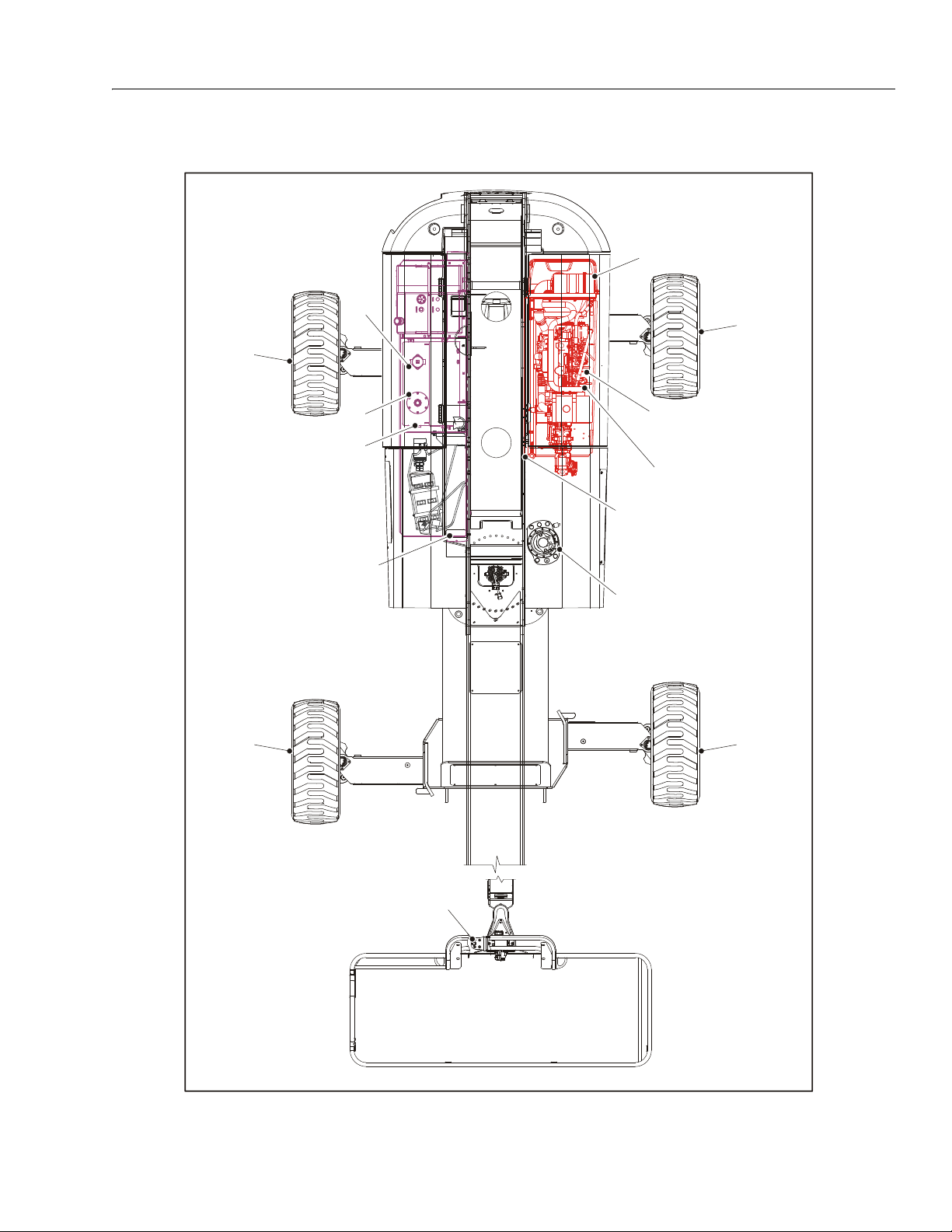
SECTION 1 - SPECIFICATIONS
4
4
4
13
4
5
7
8
1
10,11
8
12
2,3
6
Figure 1-1. Lubrication and Operator Maintenance Diagram
3121256 – JLG Lift – 1-5
Page 22

SECTION 1 - SPECIFICATIONS
1.9 LUBRICATION AND OPERATOR MAINTENANCE
NOTE: The following numbers correspond to those in Fig-
ure 1-1., Lubrication and Operator Maintenance
Diagram.
Table 1-17. Lubrication Specifications
KEY SPECIFICATIONS
MPG Multipurpose Grease having a minimum dripping point of
350° F (177° C). Excellent water resistance and adhesive
qualities, and being of extreme pressure type.
(Timken OK 40 pounds minimum.)
EPGL Extreme Pressure Gear Lube (oil) meeting API service classi-
f ic at io n G L- 5 o r M IL- S pe c M IL- L- 21 05
HO Hydraulic Oil. API ser vice classification GL-3, e.g. Mobilfluid
424.
EO Engine (crankcase) Oil. Gas - API SF, SH, SG class, MIL-L-
2104. Diesel - API CC/CD class, MIL-L-2104B/MIL-L-2104C.
LUBRICATION INTERVALS ARE BASED ON MACHINE OPERATION
UNDER NORMAL CONDITIONS. FOR MACHINES USED IN MULTISHIFT OPERATIONS AND/OR EXPOSED TO HOSTILE ENVIRONMENTS OR CONDITIONS, LUBRICATION FREQUENCIES MUST BE
INCREASED ACCORDINGLY.
2. Swing Gearbox
Lube Point(s) - Fill Plug
Capacity - 79 ounces (2.3 L)
Lube - GL-5
Interval - Check level every 150 hrs/Change every
1200 hours of operation. Fill to cover ring gear.
3. Swing Brake
NOTE: It is recommended as a good practice to replace all
filters at the same time.
1. Swing Bearing - Remote Lube
Lube Point(s) - 2 Grease Fitting
Capacity - A/R
Lube - MPG
Interval - Every 3 months or 150 hours of operation
Lube Point(s) - Fill Plug
Capacity - 2.7 ounces (80 ml)
Lube - DTE24
Interval - Check level every 150 hrs/Change every
1200 hours of operation.
1-6 – JLG Lift – 3121256
Page 23
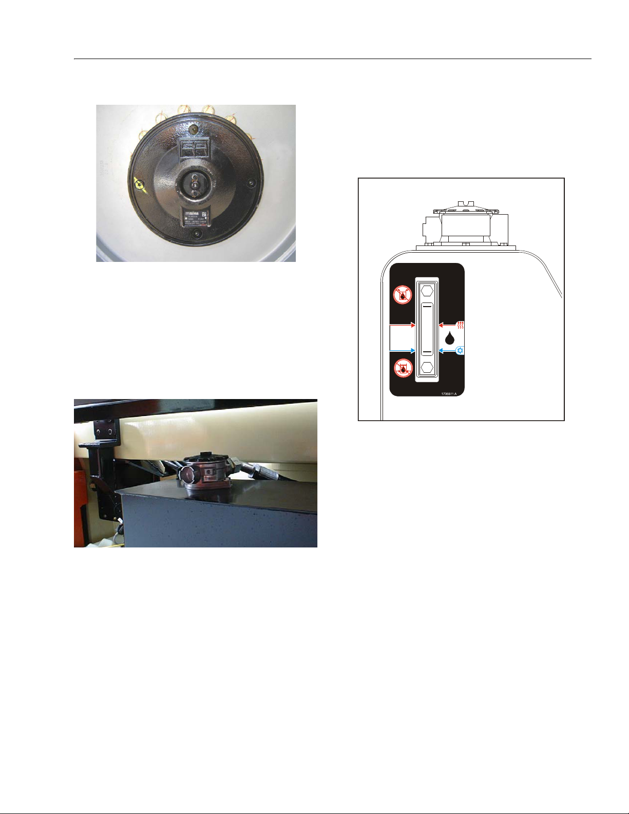
SECTION 1 - SPECIFICATIONS
FULL LEVEL (HOT OIL)
FULL LEVEL (COLD OIL)
4. Wheel Hub
Lube Point(s) - Level/Fill Plug
Capacity - 0.5 quarts (0.5 liters) ± 10%
Lube - EPGL
Interval - Change after first 150 hours then every
1200 hours of operation
Comments - Place Fill port at 12 o’clock position
and Check port at 3 o’clock position. Pour lubricant into fill port until it just starts to flow out of
check port.
5. Hydraulic Return Filter
6. Hydraulic Charge Filter
Lube Point(s) - Replaceable Element
Interval - Change after first 50 hours and every 300
hours thereafter or as indicated by condition indicator.
7. Hydraulic Oil
Lube Point(s) - Replaceable Element
Interval - Change after first 50 hours and every 300
hours thereafter or as indicated by condition indicator
Lube Point(s) - Fill Cap
Capacity - 55 gallons (208 liters) Tank
Lube - HO
Interval - Check level daily with boom down, axles
retracted, cylinders retracted. Change every 2
years or 1200 hours of operation.
3121256 – JLG Lift – 1-7
Page 24

SECTION 1 - SPECIFICATIONS
MINIMUM LEVEL,
OIL HOT
MINIMUM OIL
LEVEL
MINIMUM LEVEL,
OIL COLD
NOTE: Hot oil checks should not be made until the engine
has been shut down for a period of 5 minutes.
MAXIMUM LEVEL,
OIL HOT
MAXIMUM LEVEL,
OIL COLD
MAXIMUM OIL
LEVEL
Figure 1-2. Deutz Engine Dipstick
8. Suction Strainers (In Tank)
Lube Point(s) - 2
Interval - Every 2 years or 1200 hours of operation.
Remove and clean at time of hydraulic oil
change.
9. Oil Change w/Filter - Deutz
Lube Point(s) - Fill Cap/Spin-on Element
Capacity 5 Quarts (4.5 L) Cooling System
11 Quarts (10.5 L) Engine w/Filter
16 Quarts (15 L) Total Capacity
Lube - EO
Interval - Check level daily; change every 500 hours
or six months, whichever comes first. Adjust final
oil level by mark on dipstick. Refer to Figure 1-2.,
Deutz Engine Dipstick.
10. Fuel Filter - Deutz
Lube Point(s) - Replaceable Element
Interval - Every year or 600 hours of operation
1-8 – JLG Lift – 3121256
Page 25

SECTION 1 - SPECIFICATIONS
11. Fuel Strainer
Lube Point(s) - Replaceable Element
Interval - Every year or 600 hours of operation
12. Air Filter - Deutz
13. Platform Filter
Lube Point(s) - Replaceable Element
Interval - Change after first 50 hours and then every
year or 600 hours of operation thereafter
Lube Point(s) - Replaceable Element
Interval - Every 6 months or 300 hours of operation
or as indicated by the condition indicator
3121256 – JLG Lift – 1-9
Page 26
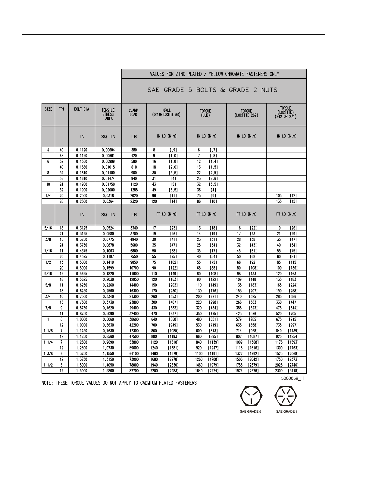
SECTION 1 - SPECIFICATIONS
Figure 1-3. Torque Chart (SAE Fasteners - Sheet 1 of 3)
1-10 – JLG Lift – 3121256
Page 27

SECTION 1 - SPECIFICATIONS
Figure 1-4. Torque Chart (SAE Fasteners - Sheet 2 of 3)
3121256 – JLG Lift – 1-11
Page 28
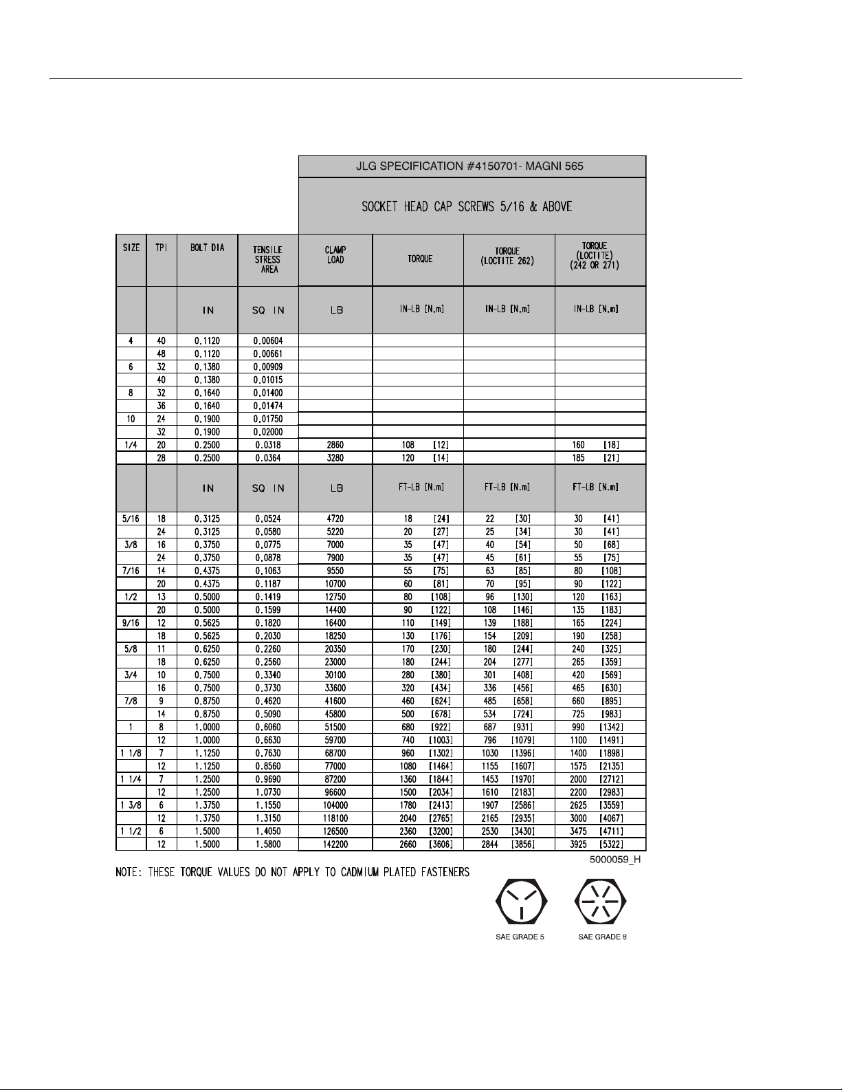
SECTION 1 - SPECIFICATIONS
Figure 1-5. Torque Chart (SAE Fasteners - Sheet 3 of 3)
1-12 – JLG Lift – 3121256
Page 29
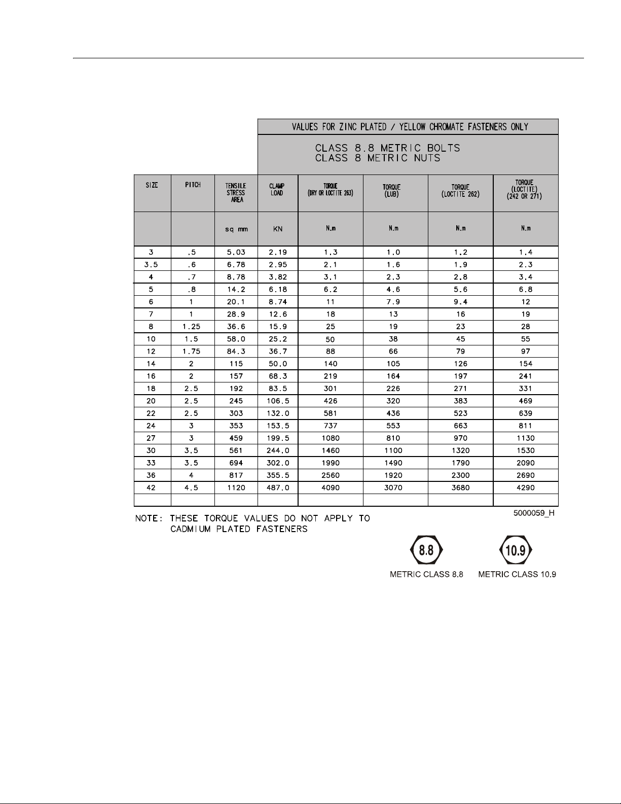
SECTION 1 - SPECIFICATIONS
Figure 1-6. Torque Chart (METRIC Fasteners - Sheet 1 of 3)
3121256 – JLG Lift – 1-13
Page 30
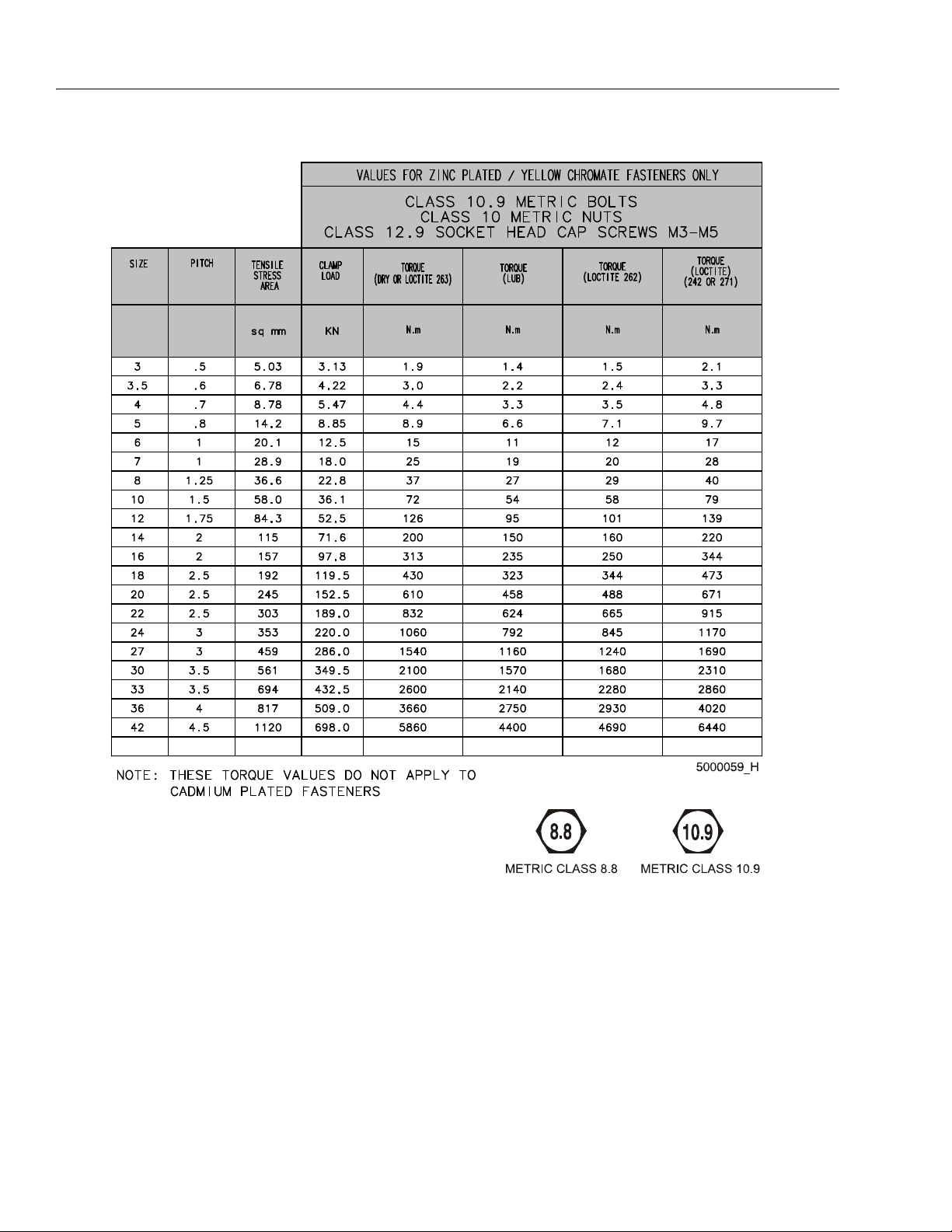
SECTION 1 - SPECIFICATIONS
Figure 1-7. Torque Chart (METRIC Fasteners - Sheet 2 of 3)
1-14 – JLG Lift – 3121256
Page 31

SECTION 1 - SPECIFICATIONS
Figure 1-8. Torque Chart (METRIC Fasteners - Sheet 3 of 3)
3121256 – JLG Lift – 1-15
Page 32

SECTION 1 - SPECIFICATIONS
NOTES:
1-16 – JLG Lift – 3121256
Page 33

SECTION 2. GENERAL
SECTION 2 - GENERAL
2.1 MACHINE PREPARATION, INSPECTION, AND MAINTENANCE
General
This section provides the necessary information needed
by those personnel that are responsible to place the
machine in operation readiness and maintain its safe
operating condition. For maximum service life and safe
operation, ensure that all the necessary inspections and
maintenance have been completed before placing the
machine into service.
Preparation, Inspection, and Maintenance
It is important to establish and conform to a comprehensive inspection and preventive maintenance program. The
following table outlines the periodic machine inspections
and maintenance recommended by JLG Industries, Inc.
Consult your national, regional, or local regulations for further requirements for aerial work platforms. The frequency
of inspections and maintenance must be increased as
environment, severity and frequency of usage requires.
Pre-Start Inspection
It is the User’s or Operator’s primary responsibility to perform a Pre-Start Inspection of the machine prior to use
daily or at each change of operator. Reference the Operator’s and Safety Manual for completion procedures for the
Pre-Start Inspection. The Operator and Safety Manual
must be read in its entirety and understood prior to performing the Pre-Start Inspection.
Pre-Delivery Inspection and Frequent Inspection
The Pre-Delivery Inspection and Frequent Inspection shall
be performed by a qualified JLG equipment mechanic.
JLG Industries, Inc. recognizes a qualified JLG equipment
mechanic as a person who, by possession of a recognized degree, certificate, extensive knowledge, training, or
experience, has successfully demonstrated the ability and
proficiency to service, repair, and maintain the subject
JLG product model.
The Pre-Delivery Inspection and Frequent Inspection procedures are performed in the same manner, but at different times. The Pre-Delivery Inspection shall be performed
prior to each sale, lease, or rental delivery. The Frequent
Inspection shall be accomplished for each machine in service for 3 months or 150 hours (whichever comes first);
out of service for a period of more than 3 months; or when
purchased used. The frequency of this inspection must be
increased as environment, severity and frequency of
usage requires.
Reference the JLG Pre-Delivery and Frequent Inspection
Form and the Inspection and Preventative Maintenance
Schedule for items requiring inspection during the performance of these inspections. Reference the appropriate
areas of this manual for servicing and maintenance procedures.
Annual Machine Inspection
The Annual Machine Inspection must be performed by a
Factory-Certified Service Technician on an annual basis,
no later than thirteen (13) months from the date of the
prior Annual Machine Inspection. JLG Industries, Inc. recognizes a Factory-Certified Service Technician as a person who has successfully completed the JLG Service
Training School for the subject JLG product model. Reference the machine Service and Maintenance Manual and
appropriate JLG inspection form for performance of this
inspection.
Reference the JLG Annual Machine Inspection Form and
the Inspection and Preventative Maintenance Schedule for
items requiring inspection during the performance of this
inspection. Reference the appropriate areas of this manual for servicing and maintenance procedures.
For the purpose of receiving safety-related bulletins, it is
important that JLG Industries, Inc. has updated ownership
information for each machine. When performing each
Annual Machine Inspection, notify JLG Industries, Inc. of
the current machine ownership.
Preventative Maintenance
In conjunction with the specified inspections, maintenance shall be performed by a qualified JLG equipment
mechanic. JLG Industries, Inc. recognizes a qualified JLG
equipment mechanic as a person who, by possession of a
recognized degree, certificate, extensive knowledge, training, or experience, has successfully demonstrated the
ability and proficiency to service, repair, and maintain the
subject JLG product model.
Reference the Preventative Maintenance Schedule and
the appropriate areas of this manual for servicing and
maintenance procedures. The frequency of service and
maintenance must be increased as environment, severity
and frequency of usage requires.
3121256 – JLG Lift – 2-1
Page 34

SECTION 2 - GENERAL
Table 2-1. Inspection and Maintenance
Type Frequency
Pre-Start Inspection Prior to use each day; or
At each Operator change.
Pre-Delivery
Inspection
Frequent Inspection In service for 3 months or 150 hours, which-
Annual Machine
Inspection
Preventative
Maintenance
Prior to each sale, lease, or
rental delivery.
ever comes first; or
Out of service for a period of more than 3
months; or
Purchased used.
Annually, no later than 13 months from the
date of the prior inspection.
At intervals as specified in the Service and
Maintenance Manual.
2.2 SERVICE AND GUIDELINES
General
The following information is provided to assist you in the
use and application of servicing and maintenance procedures contained in this book.
Safety and Workmanship
Your safety, and that of others, is the first consideration
when engaging in the maintenance of equipment. Always
be conscious of weight. Never attempt to move heavy
parts without the aid of a mechanical device. Do not allow
heavy objects to rest in an unstable position. When raising
a portion of the equipment, ensure that adequate support
is provided.
Cleanliness
1. The most important single item in preserving the
long service life of a machine is to keep dirt and foreign materials out of the vital components. Precautions have been taken to safeguard against this.
Shields, covers, seals, and filters are provided to
keep air, fuel, and oil supplies clean; however, these
items must be maintained on a scheduled basis in
order to function properly.
Primary
Responsibility
User or Operator User or Operator Operator and Safety Manual
Owner, Dealer, or User Qualified JLG
Owner, Dealer, or User Qualified JLG
Owner, Dealer, or User Factory-Certified
Owner, Dealer, or User Qualified JLG
2. At any time when air, fuel, or oil lines are disconnected, clear adjacent areas as well as the openings
and fittings themselves. As soon as a line or component is disconnected, cap or cover all openings to
prevent entry of foreign matter.
3. Clean and inspect all parts during servicing or maintenance, and assure that all passages and openings
are unobstructed. Cover all parts to keep them
clean. Be sure all parts are clean before they are
installed. New parts should remain in their containers until they are ready to be used.
Service
Qualification
Mechanic
Mechanic
Service Technician
Mechanic
Reference
Service and Maintenance
Manual and applicable JLG
inspection form.
Service and Maintenance
Manual and applicable JLG
inspection form.
Service and Maintenance
Manual and applicable JLG
inspection form.
Service and Maintenance
Manual
Components Removal and Installation
1. Use adjustable lifting devices, whenever possible, if
mechanical assistance is required. All slings (chains,
cables, etc.) should be parallel to each other and as
near perpendicular as possible to top of part being
lifted.
2. Should it be necessary to remove a component on
an angle, keep in mind that the capacity of an eyebolt or similar bracket lessens, as the angle between
the supporting structure and the component
becomes less than 90 degrees.
3. If a part resists removal, check to see whether all
nuts, bolts, cables, brackets, wiring, etc., have been
removed and that no adjacent parts are interfering.
2-2 – JLG Lift – 3121256
Page 35

SECTION 2 - GENERAL
Component Disassembly and Reassembly
When disassembling or reassembling a component, complete the procedural steps in sequence. Do not partially
disassemble or assemble one part, then start on another.
Always recheck your work to assure that nothing has been
overlooked. Do not make any adjustments, other than
those recommended, without obtaining proper approval.
Pressure-Fit Parts
When assembling pressure-fit parts, use an anti-seize or
molybdenum disulfide base compound to lubricate the
mating surface.
Bearings
1. When a bearing is removed, cover it to keep out dirt
and abrasives. Clean bearings in nonflammable
cleaning solvent and allow to drip dry. Compressed
air can be used but do not spin the bearing.
2. Discard bearings if the races and balls (or rollers)
are pitted, scored, or burned.
3. If bearing is found to be serviceable, apply a light
coat of oil and wrap it in clean (waxed) paper. Do not
unwrap reusable or new bearings until they are
ready to install.
4. Lubricate new or used serviceable bearings before
installation. When pressing a bearing into a retainer
or bore, apply pressure to the outer race. If the bearing is to be installed on a shaft, apply pressure to the
inner race.
Gaskets
Check that holes in gaskets align with openings in the
mating parts. If it becomes necessary to hand-fabricate a
gasket, use gasket material or stock of equivalent material
and thickness. Be sure to cut holes in the right location, as
blank gaskets can cause serious system damage.
Bolt Usage and Torque Application
1. Use bolts of proper length. A bolt which is too long
will bottom before the head is tight against its related
part. If a bolt is too short, there will not be enough
thread area to engage and hold the part properly.
When replacing bolts, use only those having the
same specifications of the original, or one which is
equivalent.
2. Unless specific torque requirements are given within
the text, standard torque values should be used on
heat-treated bolts, studs, and steel nuts, in accordance with recommended shop practices. (See
Torque Chart Section 1.)
Hydraulic Lines and Electrical Wiring
Clearly mark or tag hydraulic lines and electrical wiring, as
well as their receptacles, when disconnecting or removing
them from the unit. This will assure that they are correctly
reinstalled.
Hydraulic System
1. Keep the system clean. If evidence of metal or rubber particles are found in the hydraulic system, drain
and flush the entire system.
2. Disassemble and reassemble parts on clean work
surface. Clean all metal parts with non-flammable
cleaning solvent. Lubricate components, as
required, to aid assembly.
Lubrication
Service applicable components with the amount, type,
and grade of lubricant recommended in this manual, at
the specified intervals. When recommended lubricants are
not available, consult your local supplier for an equivalent
that meets or exceeds the specifications listed.
Battery
Clean battery, using a non-metallic brush and a solution of
baking soda and water. Rinse with clean water. After
cleaning, thoroughly dry battery and coat terminals with
an anti corrosion compound.
Lubrication and Servicing
Components and assemblies requiring lubrication and
servicing are shown in the Lubrication Chart in Section 1.
2.3 LUBRICATION AND INFORMATION
Hydraulic System
1. The primary enemy of a hydraulic system is contamination. Contaminants enter the system by various
means, e.g., using inadequate hydraulic oil, allowing
moisture, grease, filings, sealing components, sand,
etc., to enter when performing maintenance, or by
permitting the pump to cavitate due to insufficient
system warm-up or leaks in the pump supply (suction) lines.
2. The design and manufacturing tolerances of the
component working parts are very close, therefore,
even the smallest amount of dirt or foreign matter
entering a system can cause wear or damage to the
components and generally results in faulty operation. Every precaution must be taken to keep
hydraulic oil clean, including reserve oil in storage.
Hydraulic system filters should be checked,
cleaned, and/or replaced as necessary, at the speci-
3121256 – JLG Lift – 2-3
Page 36

SECTION 2 - GENERAL
fied intervals required in the Lubrication Chart in
Section 1. Always examine filters for evidence of
metal particles.
3. Cloudy oils indicate a high moisture content which
permits organic growth, resulting in oxidation or corrosion. If this condition occurs, the system must be
drained, flushed, and refilled with clean oil.
4. It is not advisable to mix oils of different brands or
types, as they may not contain the same required
additives or be of comparable viscosities. Good
grade mineral oils, with viscosities suited to the
ambient temperatures in which the machine is operating, are recommended for use.
NOTE: Metal particles may appear in the oil or filters of new
machines due to the wear-in of meshing components.
Hydraulic Oil
1. Refer to Section 1 for recommendations for viscosity
ranges.
2. JLG recommends Mobilfluid 424 hydraulic oil, which
has an SAE viscosity of 10W-30 and a viscosity
index of 152.
Changing Hydraulic Oil
1. Filter elements must be changed after the first 50
hours of operation and every 300 hours (unless
specified otherwise) thereafter. If it is necessary to
change the oil, use only those oils meeting or
exceeding the specifications appearing in this manual. If unable to obtain the same type of oil supplied
with the machine, consult local supplier for assistance in selecting the proper equivalent. Avoid mixing petroleum and synthetic base oils. JLG
Industries recommends changing the hydraulic oil
annually.
2. Use every precaution to keep the hydraulic oil clean.
If the oil must be poured from the original container
into another, be sure to clean all possible contaminants from the service container. Always clean the
mesh element of the filter and replace the cartridge
any time the system oil is changed.
3. While the unit is shut down, a good preventive maintenance measure is to make a thorough inspection
of all hydraulic components, lines, fittings, etc., as
well as a functional check of each system, before
placing the machine back in service.
Lubrication Specifications
NOTE: Start-up of hydraulic system with oil temperatures
below -15 degrees F (-26 degrees C) is not recommended. If it is necessary to start the system in a
sub-zero environment, it will be necessary to heat
the oil with a low density, 100VAC heater to a minimum temperature of -15 degrees F (-26 degrees C).
3. The only exception to the above is to drain and fill
the system with Mobil DTE 13 oil or its equivalent.
This will allow start up at temperatures down to -20
degrees F (-29 degrees C). However, use of this oil
will give poor performance at temperatures above
120 degrees F (49 degrees C). Systems using DTE
13 oil should not be operated at temperatures above
200 degrees F (94 degrees C) under any condition.
Specified lubricants, as recommended by the component
manufacturers, are always the best choice, however,
multi-purpose greases usually have the qualities which
meet a variety of single purpose grease requirements.
Should any question arise, regarding the use of greases in
maintenance stock, consult your local supplier for evaluation. Refer to Section 1 for an explanation of the lubricant
key designations appearing in the Lubrication Chart.
2.4 CYLINDER DRIFT TEST
Maximum acceptable cylinder drift is to be measured
using the following methods.
Platform Drift
Measure the drift of the platform to the ground. Lower
booms (if equipped) slightly elevated, main boom fully
extended with the rated load in the platform and power off.
Maximum allowable drift is 2 inches (5 cm) in 10 minutes.
If the machine does not pass this test, proceed with the
following.
2-4 – JLG Lift – 3121256
Page 37

SECTION 2 - GENERAL
Cylinder Drift
Table 2-2. Cylinder Drift
Cylinder Bore Diameter
inches mm inches mm
3 76.2 0.026 0.66
3.5 89 0.019 0.48
4 101.6 0.015 0.38
5 127 0.009 0.22
6 152.4 0.006 0.15
7 177.8 0.005 0.13
8 203.2 0.0038 0.10
9 228.6 0.0030 0.08
Drift is to be measured at the cylinder rod with a calibrated
dial indicator. The cylinder oil must be at ambient temperature and temperature stabilized.
The cylinder must have the normal load, which is the normal platform load applied.
If the cylinder passes this test, it is acceptable.
NOTE: This information is based on 6 drops per minute cyl-
inder leakage.
Max. Acceptable Drift
in 10 Minutes
b. Flaking, pealing, scoring, or scratches on the pin
surface.
c. Rusting of the pin in the bearing area.
4. Re-assembly of pinned joints using filament wound
bearings.
a. Housing should be blown out to remove all dirt
and debris...bearings and bearing housings
must be free of all contamination.
b. Bearing / pins should be cleaned with a solvent
to remove all grease and oil...filament wound
bearing are a dry joint and should not be lubricated unless otherwise instructed (i.e. sheave
pins).
c. Pins should be inspected to ensure it is free of
burrs, nicks, and scratches which would damage the bearing during installation and operation.
2.6 WELDING ON JLG EQUIPMENT
NOTE: This instruction applies to repairs, or modifications to
the machine and to welding performed from the
machine on an external structure, or component,
Do the Following When Welding on JLG Equipment
2.5 PINS AND COMPOSITE BEARING REPAIR GUIDELINES
Filament wound bearings.
1. Pinned joints should be disassembled and
inspected if the following occurs:
a. Excessive sloppiness in joints.
b. Noise originating from the joint during operation.
2. Filament wound bearings should be replaced if any
of the following is observed:
a. Frayed or separated fibers on the liner surface.
b. Cracked or damaged liner backing.
c. Bearings that have moved or spun in their hous-
ing.
d. Debris embedded in liner surface.
3. Pins should be replaced if any of the following is
observed (pin should be properly cleaned prior to
inspection):
a. Detectable wear in the bearing area.
• Disconnect the battery.
• Disconnect the moment pin connection (where fitted)
• Ground only to structure being welded.
Do NOT Do the Following When Welding on JLG Equipment
• Ground on frame and weld on any other area than the
chassis.
• Ground on turntable and weld on any other area than
the turntable.
• Ground on the platform/support and weld on any other
area than the platform/support.
• Ground on a specific boom section and weld on any
other area than that specific boom section.
• Allow pins, wear pads, wire ropes, bearings, gearing,
seals, valves, electrical wiring, or hoses to be between
the grounding position and the welded area.
FAILURE TO COMPLY WITH THE ABOVE REQUIREMENTS MAY
RESULT IN COMPONENT DAMAGE (I.E. ELECTRONIC MODULES,
SWING BEARING, COLLECTOR RING, BOOM WIRE ROPES ETC.)
3121256 – JLG Lift – 2-5
Page 38

SECTION 2 - GENERAL
Table 2-3. Inspection and Preventive Maintenance Schedule
INTERVAL
AREA
Boom Assembly
Boom Weldments 1,2,4 1,2,4
Hose/Cable Carrier Installations 1,2,9,12 1,2,9,12
Pivot Pins and Pin Retainers 1,2 1,2
Sheaves, Sheave Pins 1,2 1,2
Bearings 1,2 1,2
Wear Pads 1,2 1,2
Covers or Shields 1,2 1,2
Extend/Retract Chain or Cable Systems 1,2,3 1,2,3
Platform Assembly
Platform 1,2 1,2
Railing 1,2 1 1,2
Gate 511,5
Floor 1,2 1 1,2
Rotator 9,5 15
Lanyard Anchorage Point 2 1,2,10 1,2,10
Turntable Assembly
Swing Bearing or Worm Gear 1,2,14 1,2,3,13,14
Oil Coupling 9
Swing Drive System 11 11
Turntable Lock 1,2,5 1,2,5
Hood, Hood Props, Hood Latches 51,2,5
Chassis Assembly
Tires 1 16,17 16,17,18 16,17,18
Wheel Nuts/Bolts 115 1515
Wheel Bearings 14,24
Oscillating Axle/Lockout Cylinder Systems 5,8
Outrigger or Extendable Axle Systems 5,8 5,8
Steer Components
Drive Motors
Drive Hubs 11 11
Functions/Controls
Platform Controls 55 66
Pre-Start
Inspection
9
9
9
9
9
1
Maintenance
Weekly
Preventive
Monthly
Preventive
Maintenance
Pre-Delivery
or Frequent
Inspection
2
3
Annual
(Yearly)
Inspection
4
Every 2
Years
2-6 – JLG Lift – 3121256
Page 39

SECTION 2 - GENERAL
Table 2-3. Inspection and Preventive Maintenance Schedule
INTERVAL
AREA
Pre-Start
Inspection
1
Preventive
Maintenance
Weekly
Monthly
Preventive
Maintenance
Pre-Delivery
or Frequent
Inspection
2
3
Ground Controls 55 66
Function Control Locks, Guards, or Detents 1,5 1,5 5 5
Footswitch 1,5 5 5
Emergency Stop Switches (Ground & Platform) 555
Function Limit or Cutout Switch Systems 555
Capacity Indicator 5
Drive Brakes 5
Swing Brakes 5
Boom Synchronization/Sequencing Systems 5
Manual Descent or Auxiliary Power 55
Power System
9
Engine Idle, Throttle, and RPM 33
Engine Fluids (Oil, Coolant, Fuel) 11 9,11 11 11
Air/Fuel Filter 1,7 7 7
Exhaust System 1,9 9 9
Batteries 51,9 19
Battery Fluid 11 11 11
Battery Charger 55
Fuel Reservoir, Cap, and Breather 11,9 2 1,5 1,5
Hydraulic/Electric System
9
Hydraulic Pumps 1,9 1,2,9
Hydraulic Cylinders 1,9,7 2 1,2,9 1,2,9
Cylinder Attachment Pins and Pin Retainers 1,9 1,2 1,2
Hydraulic Hoses, Lines, and Fittings 1,9 12 1,2,9,12 1,2,9,12
Hydraulic Reservoir, Cap, and Breather 11 1,9 2 1,5 1,5 24
Hydraulic Filter 1,9 7 7
Hydraulic Fluid 11 7,11 7,11
Electrical Connections 12020
Instruments, Gauges, Switches, Lights, Horn 15,23
General
Operators and Safety Manuals in Storage Box 21 21 21
ANSI and EMI Manuals/Handbooks Installed 21
Capacity Decals Installed, Secure, Legible 21 21 21
All Decals/Placards Installed, Secure, Legible 21 21 21
Annual
(Yearly)
Inspection
4
Every 2
Years
3121256 – JLG Lift – 2-7
Page 40

SECTION 2 - GENERAL
Table 2-3. Inspection and Preventive Maintenance Schedule
INTERVAL
AREA
Pre-Start
Inspection
1
Maintenance
Weekly
Preventive
Monthly
Preventive
Maintenance
Pre-Delivery
or Frequent
Inspection
2
3
Walk-Around Inspection Performed 21
Annual Machine Inspection Due 21
No Unauthorized Modifications or Additio ns 21 21
All Relevant Safety Publications Incorporated 21 21
General Structural Condition and Welds 2,4 2,4
All Fasteners, Pins, Shields, and Covers 1,2 1,2
Grease and Lubricate to Specifications 22 22
Function Test of All Systems 21 21 21, 22
Paint and Appearance 77
Stamp Inspection Date on Frame 22
Notify JLG of Machine Ownership 22
Footnotes:
1
Prior to use each day; or at each Operator change
2
Prior to each sale, lease, or delivery
3
In service for 3 months or 150 Hours; or Out of service for 3 months or more; or Purchased use d
4
Annually, no later than 13 months from the date of the prior inspection
Performance Codes:
1 - Check for proper and secure installation
2 - Visual inspection for damage, cracks, distortion or exc essive wear
3 - Check for proper adjustment
4 - Check for cracked or broken welds
5 - Operates Properly
6 - Returns to neutral or "off" position when released
7 - Clean and free of debris
8 - Interlocks function properly
9 - Check for signs of leakage
10 - Decals installed and legible
11 - Check for proper fluid level
12 - Check for chafing and proper routing
13 - Check for proper tolerances
14 - Properly lubricated
15 - Torqued to proper specification
16 - No gouges, excessive wear, or cords showing
17 - Properly inflated and seated around rim
18 - Proper and authorized components
19 - Fully charged
20 - No loose connections, corrosion, or abrasions
21 - Verify
22 - Perform
23 - Sealed Properly
24 - Drain, Clean, Refill
Annual
(Yearly)
Inspection
4
Every 2
Years
2-8 – JLG Lift – 3121256
Page 41

SECTION 2 - GENERAL
-40 F (-40C)
-30 F(-34C)
-20 F(-29C)
-10 F(-23C)
0F(-18C)
10 F(-12C)
20 F ( -7C)
30 F ( -1C)
40 F( 4C)
50 F (10C)
60 F (16C)
70 F(21 C)
80 F(27 C)
90 F(32 C)
100 F(38 C)
110 F(43 C)
120 F(49 C)
ENGINE
SPECIFICATIONS
ENGINE WILL START AND OPERATE AT THIS TEMPERATURE
WITH THE RECOMMENDED FLUIDS, A FULLY CHARGED BATTERY
AND THE AID OF A COMPLETE JLG SPECIFIED COLD WEATHER
PACKAGE (IE. ENGINE BLOCK HEATER, ETHER INJECTION OR
GLOW PLUGS, BATTERY WARMER AND HYDRAULIC OIL TANK HEATER)
ENGINE WILL START AND OPERATE UNAIDED AT THIS
TEMPERATURE WITH THE RECOMMENDED FLUIDS AND A
FULLY CHARGED BATTERY.
AMBIENT AIR
TEMPERATURE
SUMMER
GR ADE
FUEL
WINT ER
GR ADE
FUEL
WINT ER
GR ADE
FUEL
WIT H
KEROSENE
ADDED
NO OPERATION BELOW THIS
AMBIENT TEMPERATURE
NO OPERATION ABOVE THIS
AMBIENT TEMPERATURE
(HYD. OIL TANK TEMP.)
IF EITHER OR BOTH CONDITIONS
EXIST JLG HIGHLY RECOMMENDS
THE ADDITION OF A HYDRAULIC
OIL COOLER (CONSULT JLG SERVICE
180° F (82° C)
-40° F (-40° C)
-30° F (-34° C)
-20° F (-29° C)
-10° F (-23° C)
0° F (-18° C)
10° F (-12° C)
20° F (-7° C)
30° F (-1° C)
40° F (4° C)
50° F (10° C)
60° F (16° C)
70° F (21° C)
80° F (27° C)
90° F (32° C)
100° F (38° C)
110° F (43° C)
120° F (49° C)
AMBIENT AIR
TEMPERATURE
PROLONGED OPERATION IN
AMBIENT AIR TEMPERATURES
OF 100°F (38°C) OR ABOVE.
EXTENDED DRIVING WITH HYDRAULIC OIL TANK
TEMPERATURES OF 180°F (82°C) OR ABOVE.
NO OPERATION BELOW THIS
AMBIENT TEMPERATURE
M
O
B
I
L
4
2
4
1
0
W
-
3
0
HYDRAULIC
SPECIFICATIONS
NO OPERATION ABOVE THIS
AMBIENT TEMPERATURE
DO NOT START UP HYDRAULIC SYSTEM
WITHOUT HEATING AIDS WITH MOBILE 424
HYDRAULIC OIL BELOW THIS TEMPERATURE
DO NOT START UP HYDRAULIC SYSTEM
WITHOUT HEATING AIDS AND COLD WEA THER
HYDRAULIC OIL BELOW THIS TEMPERATURE
E
X
X
O
N
U
N
I
V
I
S
H
V
I
2
6
M
O
B
I
L
D
T
E
1
3
NOT E:
1) RECOMME NDAT ION S ARE FOR AMB IE NT TEMPERATURES
CO NS ISTANTLY W ITHIN SHOWN LIMITS
2) ALL V AL UES ARE ASSUMED T O BE AT SEA LEVEL.
0+32
-5
-10
-15
-20
-25
-30
+23
+14
+5
-4
-13
-22
CF
0 102030405060
% OF ADDED K E ROSENE
A
M
B
I
E
N
T
T
E
M
P
E
R
A
T
U
R
E
SUMMER-GRADE
FUEL
WINT ER-GR ADE
FUEL
Figure 2-1. Engine Operating Temperature Specifications - Deutz
4150548 E
3121256 – JLG Lift – 2-9
Page 42

SECTION 2 - GENERAL
NOTES:
2-10 – JLG Lift – 3121256
Page 43

SECTION 3 - CHASSIS & TURNTABLE
SECTION 3. CHASSIS & TURNTABLE
3.1 TIRES & WHEELS
Tire Inflation
The air pressure for pneumatic tires must be equal to the
air pressure that is stenciled on the side of the JLG product or rim decal for safe and proper operational characteristics.
Tire Damage
For pneumatic tires, JLG Industries, Inc. recommends that
when any cut, rip, or tear is discovered that exposes sidewall or tread area cords in the tire, measures must be
taken to remove the JLG product from service immediately. Arrangements must be made for replacement of the
tire or tire assembly.
For polyurethane foam filled tires, JLG Industries, Inc. recommends that when any of the following are discovered,
measures must be taken to remove the JLG product from
service immediately and arrangements must be made for
replacement of the tire or tire assembly.
• a smooth, even cut through the cord plies which
exceeds 3 inches (7.5 cm) in total length
• any tears or rips (ragged edges) in the cord plies which
exceeds 1 inch (2.5 cm) in any direction
• any punctures which exceed 1 inch in diameter
• any damage to the bead area cords of the tire
Tighten the lug nuts to the proper torque to prevent
wheels from coming loose. Use a torque wrench to tighten
the fasteners. If you do not have a torque wrench, tighten
the fasteners with a lug wrench, then immediately have a
service garage or dealer tighten the lug nuts to the proper
torque. Over-tightening will result in breaking the studs or
permanently deforming the mounting stud holes in the
wheels.
The proper procedure for attaching wheels is as follows:
1. Start all nuts by hand to prevent cross threading. DO
NOT use a lubricant on threads or nuts.
2. Tighten nuts in the following sequence:
If a tire is damaged but is within the above noted criteria,
the tire must be inspected on a daily basis to insure the
damage hasn’t propagated beyond the allowable criteria.
Wheel and Tire Replacement
The rims installed on each product model have been
designed for stability requirements which consist of track
width, tire pressure, and load capacity. Size changes such
as rim width, center piece location, larger or smaller diameter, etc., without written factory recommendations, may
result in an unsafe condition regarding stability.
Wheel Installation
It is extremely important to apply and maintain proper
wheel mounting torque.
WHEEL NUTS MUST BE INSTALLED AND MAINTAINED AT THE
PROPER TORQUE TO PREVENT LOOSE WHEELS, BROKEN STUDS,
AND POSSIBLE DANGEROUS SEPARATION OF WHEEL FROM THE
AXLE. BE SURE TO USE ONLY THE NUTS MATCHED TO THE CONE
ANGLE OF THE WHEEL.
3121256 – JLG Lift – 3-1
3. The tightening of the nuts should be done in stages.
Following the recommended sequence, tighten nuts
per wheel torque chart.
Table 3-1. Wheel Torque Chart
TORQUE SEQUENCE
1st Stage 2nd Stage 3rd Stage
45 ft. lbs.
(60 Nm)
4. Wheel nuts should be torqued before first road use
and after each wheel removal. Check and torque
every 3 months or 150 hours of operation.
100 ft. lbs.
(140 Nm)
180 ft. lbs.
(252 Nm)
Page 44

SECTION 3 - CHASSIS & TURNTABLE
Figure 3-1. Axle Limit Switch Adjustment
3.2 EXTENDING AXLES
The Axle Extension System allows each of the four axles
to be extended and retracted together while maintaining
full steering control as the machine is driven. The system
allows the axles to extend or retract only while the boom is
in the transport position and in order to minimize wheel
scrubbing during axle movement, a minimum drive speed
must be attained before axle extension/retraction will be
permitted. The system uses four limit switches (one at
each axle) to sense when the axles are fully extended. If
any of the switches are not made, the control system considers the axles retracted. To extend/retract the axles, the
user engages the axle extend/retract switch on the platform console and the drive control at the same time. The
axle set indicator will be off when the axles are not fully
extended and the axle extend/retract switch is not
engaged. It will flash while the axles are extending or
retracting and will be on constantly when the axles are
fully extended. With the axles not fully extended, the boom
is restricted to operation within the transport position. If a
signal from any axle extend sensing switch is lost when
the boom beyond the transport position, the axle set indicator will flash and drive/steer functions will be disabled
until the boom is brought back into the transport position.
The steering angle will be automatically limited to +/- 25
degrees anytime the axles are not fully extended. If the
wheel angle is more than +/- 25 degrees when the axle
retract command is engaged, the control system will auto-
matically reduce the wheel angle to 25 degrees during
axle retraction.
NOTE: For more detailed information concerning system
adjustment and operation, refer to Section 6 - JLG
Control System.
3.3 AXLE LIMIT SWITCH ADJUSTMENT PROCEDURE
1. Fully extend the axles.
2. Initially position the limit switch arm straight.
3. Select the mounting plate bolt pattern to position the
switch roller within 0.125 inches (3.1 mm) from the
edge of the axle cutout. It may be necessary to reposition the switch arm ±10° to accomplish this.
4. Ensure the arm will clear the axle (without bottoming
out to 70° stroke of the switch) in the retracted position.
5. Check for proper operation. Axle set light is to deactivate when the axle is retracted 0.625 inches (16
mm) maximum from fully extended.
3-2 – JLG Lift – 3121256
Page 45

3.4 DRIVE SYSTEM (1100SJP)
Figure 3-2. Conventional Two Wheel Steer Mode
Figure 3-3. Crab Steer Mode - 1100SJP Only
Figure 3-4. Coordinated Steer Mode - 1100SJP Only
The drive system utilizes 2 traction pumps so each side is
powered individually. This produces maximum tractive
effort to wheels by minimizing flow divider losses. The
maximum drive speed is modulated with the steered
angle of the wheels to eliminate the whiplash effect of driving at full speed and maximum steering lock.
3.5 STEERING CONTROL SYSTEM
NOTE: The following description covers all modes of steer-
ing. The 1100S only utilizes the Conventional Two
Wheel Steer Mode.
Each wheel is individually steered by means of a closed
circuit control system utilizing a steer sensor on each
wheel, 4 steer cylinders, and proportional valves.
The control system senses the wheel position in relation
to the steering command (direction and steering mode)
and automatically synchronizes the movement of all 4
wheels to the desired position.
SECTION 3 - CHASSIS & TURNTABLE
There are three different modes of steering selectable by
the position of the steer select switch on the platform control panel: conventional two wheel steering, crab and
coordinated. These are shown below.
Each wheel has its own steer cylinder, wheel angle sensor,
and proportional valve, allowing the control system to
position each wheel to the ideal angle for all steering
modes and all steering commands. Changes in steering
modes while the footswitch is depressed causes the
wheels to automatically adjust to the appropriate angle for
the selected steering mode based on the position of the
inside front wheel. If the steer select switch is changed
without the footswitch depressed or the EMS is off, the
wheels will not move until the footswitch is depressed and
a steering or drive command has been initiated. The steering angles are limited to +/- 25 degrees anytime the axles
are not fully extended. If a wheel cannot achieve its commanded angle within a specified time, it is considered
jammed. When a wheel is considered jammed during
steering, a fault is reported and the remaining wheels will
continue to their commanded position. The fault is cleared
when the footswitch is cycled. If a wheel is jammed making it significantly out of position, with regard to the other
wheels, the drive motors are restricted to their maximum
displacement (slow speed). Wheel angle sensor failures
will result in an approximated steering control logic that
3121256 – JLG Lift – 3-3
Page 46

SECTION 3 - CHASSIS & TURNTABLE
will allow the operator to move the machine until it can be
repaired. The wheel at the failed sensor will be driven
based on the information available from the other sensors.
This wheel will not track perfectly and will become farther
out of position over time. When the wheel becomes prohibitively out of position, the wheels can be re synchronized by fully steering against the mechanical stops.
NOTE: For more detailed information concerning system
adjustment and operation, refer to Section 6 - JLG
Control System.
3.6 DRIVE/STEERING SPEED CONTROL
The Drive/Steering Speed Control system uses the steering sensors from the steering control system to increase
operator control and comfort by reducing the effect of
turning the chassis on the resulting lateral platform speed.
The system proportionally varies the drive speed based
on the predicted turning radius of the chassis for both
coordinated and conventional two wheel steer modes.
The tighter the turn the slower the allowable drive speed.
As crab steer does not steer on a radius, full drive speed is
maintained regardless of steer angle.
NOTE: For more detailed information concerning system
adjustment and operation, refer to Section 6 - JLG
Control System.
3.7 TRACTION CONTROL SYSTEM
3.8 DRIVE ORIENTATION SYSTEM
The Drive Orientation System (DOS) is intended to indicate to the operator conditions that could make the direction of movement of the chassis different than the
direction of movement of the drive/steer control handle.
The system indicates to the operator the need to match
the black and white directional arrows on the platform
control panel to the arrows on the chassis. The system
uses a proximity switch mounted on the hydraulic swivel,
an indicator light and an override switch on the platform
display panel. The proximity switch trips when the turntable is swung +/- 45 degrees off center of the normal driving position. This occurs roughly when the boom is swung
past a rear tire. When the turntable is in the normal drive
position with the boom between the rear tires, no indications or interlocks are made. When the machine is actively
driving when the turntable is swung past the switch point,
the system is ignored until drive/steer is released. When
drive is initiated with the boom swung past the switch
point, the DOS indicator will flash and the drive/steer functions will be disabled. The operator must engage the DOS
override switch to enable Drive/steer (high drive will
remain disabled). When the DOS is enabled, the DOS
indicator will be illuminated continuously and a 3-second
enable timer will be started and will continue for 3 seconds after the end the last drive/steer command. If the
timer expires, the DOS override switch must be reengaged to enable drive/steer.
NOTE: For more detailed information concerning system
adjustment and operation, refer to Section 6 - JLG
Control System.
The traction control system uses the steering sensors
from the steering control system to optimize the performance of the drive system. This is especially important
due to the disparity of wheel speeds generated between
the inside and outside wheels of the extended axle chassis with large steering angle capability. The steering sensors are used to predict the rolling path and therefore the
required wheel speed of each wheel as the steering
angles change and steering modes change. The control
system can then command the ideal flow from each of the
two drive pumps, one for the right side of the machine and
one for he left side. On 1100SJP machines, two flow dividers, one for the right side front to back and one for the left
side front to back absorb the variation in wheel speed
front to back.
NOTE: For more detailed information concerning system
adjustment and operation, refer to Section 6 - JLG
Control System.
3-4 – JLG Lift – 3121256
Page 47

SECTION 3 - CHASSIS & TURNTABLE
This page left blank intentionally.
3121256 – JLG Lift – 3-5
Page 48

SECTION 3 - CHASSIS & TURNTABLE
1
235
8
9
11
12
14
15
1001112761-A
Figure 3-5. Chassis Component Location (1100S) - Sheet 1 of 2
3-6 – JLG Lift – 3121256
Page 49

SECTION 3 - CHASSIS & TURNTABLE
1. Axle Limit Switch (Right Front)
2. Steer Angle Sensor (Right Front)
3. Steer Valve (Front)
4. Not Used
5. Traction Valve
6. Not Used
7. Not Used
8. Axle Limit Switch (Right Rear)
9. Axle Limit Switch (Left Rear)
10. Not Used
11. Chassis Module
12. Swivel/Collector Ring
13. Not Used
14. Steer Angle Sensor (Left Front)
15. Axle Limit Switch (Left Front)
Figure 3-6. Chassis Component Location (1100S) - Sheet 2 of 2
3121256 – JLG Lift – 3-7
Page 50

SECTION 3 - CHASSIS & TURNTABLE
1001112761-A
1
272324
29
28
22
21
20
19
18
12
13
17
16
15
14
7
8
9
10
11
36
35
34
33
32
30
6
37
384414039
3
Figure 3-7. Turntable and Boom Component Location (1100SS) - Sheet 1 of 2
3-8 – JLG Lift – 3121256
Page 51

SECTION 3 - CHASSIS & TURNTABLE
1. Platform Control Valve
2. Not Used
3. Platform Level Sensor (Secondary - Left)
4. Tail Lights
5. Not Used
6. Alarm
7. Main Control Valve
8. Auxiliary Power Pump
9. Auxiliary Power Relay
10. Chassis Power Distribution Relay
11. Headlight/Tail Light Relay
12. Horn
13. Lift Cylinder Pivot Pin
14. Fuel Level Sensor
15. B.L.A.M. Module
16. Strobe Light
17. Headlight
18. Ground Control Box
19. Boom Angle Sensor (Lef t)
20. Broken Cable Proximity Switch
21. Boom Length Sensor
22. Boom Angle Sensor (Right )
23. Headlight
24. Deutz EMR2 Module
25. Not Used
26. Not Used
27. Alternator
28. Throttle Actuator
29. Oil Temperature Switch
30. Oil Pressure Switch
31. In Head Glow Plug
32. Engine Speed Sensor
33. Starter
34. Drive Pump (Right S ide)
35. Drive Pump (Left Side)
36. Function Pump
37. Starter Relay
38. Glow Plug Relay
39. Swivel/Collector Ring
40. Transport Limit Switch
41. Platform Level Sensor (Primary - Right)
42. Not Used
Figure 3-8. Turntable and Boom Component Location (1100SS) - Sheet 2 of 2
3121256 – JLG Lift – 3-9
Page 52

SECTION 3 - CHASSIS & TURNTABLE
Figure 3-9. Chassis Component Location (1100SJP) - Sheet 1 of 2
3-10 – JLG Lift – 3121256
Page 53

SECTION 3 - CHASSIS & TURNTABLE
1. Axle Limit Switch (Right Front)
2. Steer Angle Sensor (Ri ght Front)
3. Steer Valve (Front)
4. Axle Lockout Valve
5. Traction Valve
6. Steer Valve (Rear)
7. Steer Angle Sensor (Ri ght Rear)
8. Axle Limit Switch (Right Rear)
9. Axle Limit Switch (Left Rear)
10. Steer Angle Sensor (Left Rear)
11. Chassis Module
12. Swivel/Collector Ring
13. Axle Lockout Pressure Switch
14. Steer Angle Sensor (Left Front)
15. Axle Limit Switch (Left Front)
Figure 3-10. Chassis Component Location (1100SJP) - Sheet 2 of 2
3121256 – JLG Lift – 3-11
Page 54

SECTION 3 - CHASSIS & TURNTABLE
0274660-D
1
272523
242928
26
22
21
20
19
18
12
13
17
16
15
14
7
8
9
10
11
36
35
34
33
32
30
6
37538
4
41
40
2
39
3
Figure 3-11. Turntable and Boom Component Location (1100SJP) - Sheet 1 of 2
3-12 – JLG Lift – 3121256
Page 55

SECTION 3 - CHASSIS & TURNTABLE
1. Platform Control Valve
2. Jib Stow Switch
3. Platform Level Sensor (Secondary - Left)
4. Tail Lights
5. Alarm
6. Main Control Valve
7. Auxiliary Power Pump
8. Auxiliary Power Relay
9. Chassis Power Distribution Relay
10. Headlight/Tail Light Relay
11. Horn
12. Lift Cylinder Pivot Pin
13. Fuel Level Sensor
14. B.L.A.M. Module
15. Strobe Light
16. Headlight
17. Ground Control Box
18. Boom Angle Sensor (Lef t)
19. Broken Cable Proximity Switch
20. Boom Length Sensor
21. Boom Angle Sensor (Right)
22. Headlight
23. Deutz EMR2 Module
24. 110V / 220V Generator
25. Generator Control Box
26. Alternator
27. Throttle Actuator
28. Oil Temperature Switch
29. Oil Pressure Switch
30. In Head Glow Plug
31. Engine Speed Sensor
32. Starter
33. Drive Pump (Right S ide)
34. Drive Pump (Left Side)
35. Function Pump
36. Starter Relay
37. Glow Plug Relay
38. Swivel/Collector Ring
39. Transport Limit Switch
40. Platform Level Sensor (Primary - Right)
41. Dual Capacity Jib Position Switch
Figure 3-12. Turntable and Boom Component Location (1100SJP) - Sheet 2 of 2
3121256 – JLG Lift – 3-13
Page 56

SECTION 3 - CHASSIS & TURNTABLE
3
1
2
6
DETAIL A
DETAIL B
5
4
Figure 3-13. Oscillating Axle - Sheet 1 of 2
* AXLE WEAR PAD SHIMMING PROCEDURE:
1 . D O N O T S H I M B O T TO M WE A R P AD S .
2. AXLE SIDE PADS MAY BE SHIMMED UNEVENLY IF NEC ESSARY TO MAXIMIZE CONTACT AREA OF TOP WEAR PAD.
3. SHIM AXLE WEAR PADS TO WITHIN THE THICKNESS OF
THE THINNEST SHIM AT THE NARROWEST POINT THORUGH
THE WEAR PAD’S TRAVEL.
3-14 – JLG Lift – 3121256
Page 57

SECTION 3 - CHASSIS & TURNTABLE
398
7
DETAIL A
DETAIL B
4
6
11,12,A,G
10
11,12,B,G
11,12,C,G
11,12,E,G
11,12,D,G
11,12,F,G
2
1. Axle Oscillation Cylinder
2. Axle
3. Axle Powertrack
4. Extension Cylinder
5. Axle Pivot Pin
6. Axle Limit Switch
7. Axle Stop Pin
8. Rubber Pad
9. Hose Clamp
10. Stop Block
11. Wear Pad
12. Shim
Figure 3-14. Oscillating Axle - Sheet 2 of 2
A - Assemble to Axle Box Mid Plate; Typical 8 Places
B- Assemble to Top Plate of Axle Boxes; Typical 4 Places; Torque; Select appropriate bolt
to ensure 0.5 ±0.062 inches (12.7 ± 1.587 mm) thread engagement.
C - Assemble to Side Plates of Axle Weldments; Typical 16 Places.
D - Assemble to Front and Rear Plates o f A x le B ox e s ; Ty p ic a l 8 P l ac e s.
E - Assemble to Top Plate of Axle Weldment; Typ ic a l 4 P la c es ; Tor q ue ; Se l ec t ap p ro p ri a te
bolt to ensure 0.5 ±0.062 inches (12.7 ± 1.587 mm) thread engagement.
F - Assemble to Bottom Plate of Axle Box Weldment; Typical 8 Places.
G - See Axle Wear Pad Shimming Procedure on Sheet 1
3121256 – JLG Lift – 3-15
Page 58

SECTION 3 - CHASSIS & TURNTABLE
6
2
3
DETAIL A
*
DETAIL B
4
Figure 3-15. Fixed Axle - Sheet 1 of 2
* AXLE STOP SHIMMING PROCEDURE:
1. ALL FOUR WHEELS OF THE MACHINE SHOULD
BE ON A LEVEL SURFACE WITH THE TURNTABLE
SQUARE TO THE FRAME.
2. SHIM AXLE STOPS TO WITHIN THE THICKNESS OF
THE THINNEST SHIM.
3-16 – JLG Lift – 3121256
Page 59

SECTION 3 - CHASSIS & TURNTABLE
398
7
DETAIL A
DETAIL B
4
6
11,12,A,G
10
11,12,B,G
11,12,C,G
11,12,E,G
11,12,E,G
11,12,F,G
2
1. Not Used
2. Axle
3. Axle Power track
4. Extension Cylinder
5. Not Used
6. Axle Limit Switch
7. Axle Stop Pin
8. Rubber Pad
9. Hose Clamp
10. Stop Block
11. Wear Pad
12. Shim
Figure 3-16. Fixed Axle - Sheet 2 of 2
A - Assemble to Axle Box Mid Plate; Typical 8 Places
B- Assemble to Top Plate of Axle Boxes; Typical 4 Places; Torque; Select appropriate bolt
to ensure 0.5 ±0.062 inches (12.7 ± 1.587 mm) thread engagement.
C - Assemble to Side Plates of Axle Weldments; Typical 16 Places.
D - Assemble to Front and Rear Plates o f A x le B ox e s ; Ty p ic a l 8 P l ac e s.
E - Assemble to Top Plate of Axle Weldment; Typ ic a l 4 P la c es ; Tor q ue ; Se l ec t ap p ro p ri a te
bolt to ensure 0.5 ±0.062 inches (12.7 ± 1.587 mm) thread engagement.
F - Assemble to Bottom Plate of Axle Box Weldment; Typical 8 Places.
G - See Axle Stop Shimming Procedure on Sheet 1
3121256 – JLG Lift – 3-17
Page 60

SECTION 3 - CHASSIS & TURNTABLE
Figure 3-17. Axle Loctite Application
3-18 – JLG Lift – 3121256
Page 61

SECTION 3 - CHASSIS & TURNTABLE
SECTION
A-A
ASSEMBLE SEAL, FOLLOWED BY SEAL CAP,
AND FASTENED BY FLAT HEAD CAP SCREW
TYP ASSEMBLY ON TOP OF ALL STEER CYLINDER PINS
1
2
3
B
4,5
6
7
8
9,10,A
A
11,12,A,D
13
14
B,15
Figure 3-18. Steering Installation - Sheet 1 of 3
1. Bearing
2. Thrust Washer
3. King Pin
4. Outer Pin Seal Cap
5. Outer Pin Seal
6. Spindle
7. Non-Steer Link
8. Inner Pin
9. Inner Pin Seal Cap
10. Inner Pin Seal
11. Slotted Nut
12. Co tter Pin
13. Thr ust Washer
14. Outer P in
15. Keeper
Table 3-2. Steering Assembly Notes
A
Apply Loctite #242
B
Apply Loctite #271
C
Apply Loctite #222
D
Preload Torque 100-300 ft. lb. (140-420
Nm) on Slot Nut
NON-STEER AXLE
3121256 – JLG Lift – 3-19
Page 62

SECTION 3 - CHASSIS & TURNTABLE
B
B
26
B,25
24
23
27
28
29
16
17
20,21,22,A,D
A
30
18
19
A
Figure 3-19. Steering Installation - Sheet 2 of 3
16. Spindle
17. Steer Cylinder
18. Inner Pin
19. Thr ust Washer
20. Slotted Nut
21. Washer
22. Cotter Pin
23. Thr ust Washer
24. Outer Pin
25. Keeper
26. Thr ust Washer
27. Thr ust Washer
28. King Pin
29. Outer Pin Seal
30. Inner Pin Seal
STEER AXLE
3-20 – JLG Lift – 3121256
Page 63

SEE DETAIL
A
SENSOR COVER NOT SHOWN.
SENSOR SHOWN IN PHANTOM
FOR CLARITY
ASSEMBLE SEAL, FOLLOWED BY SEAL CAP,
AND FASTENED BY FLAT HEAD CAP SCREW
TYP ASSEMBLY ON TOP OF ALL STEER CYL I ND ER PINS
36, 37, A
32, 33, A
34
35
38
C
B
A
31, C
Figure 3-20. Steering Installation - Sheet 3 of 3
31. Terminal Base
32. Outer Pin Seal Cap
33. Outer Pin Seal
34. Angle S ensor Cover
35. Angle S ensor Arm
36. Inn er Pin Seal Cap
37. Inn er Pin Seal
38. Ang le Sensor Switch
STEER AXLE
SECTION 3 - CHASSIS & TURNTABLE
3121256 – JLG Lift – 3-21
Page 64

SECTION 3 - CHASSIS & TURNTABLE
3.9 OSCILLATING AXLE SYSTEM (1100SJP)
The oscillating front axle is attached to the frame by a
pivot pin, which allows all four wheels to remain on the
ground when traveling on rough terrain. The oscillating
axle also incorporates two lockout cylinders connected
between the frame and the axle. The lockout cylinders
permit axle oscillation when the boom is in the transport
position and drive is commanded. The lockout cylinders
will lock and hold the axle when drive is not commanded
or when the boom is outside the transport position. The
cylinders unlock when pilot pressure is applied to the
holding valves mounted on the cylinders and lock when
pilot pressure is removed. Pilot pressure is available from
brake pressure and is controlled by a solenoid operated
NC lockout valve mounted in the frame. To ensure the
lockout valve is functioning correctly, a NO pressure
switch is mounted between the lockout valve and the
holding valves. The system is “healthy” when pressure
trips the pressure switch when the lockout valve is commanded to be open and conversely is healthy when the
lack of pressure resets the pressure switch when the lockout valve is commanded to be closed. Failures in the
oscillating axle system will cause the control system to
disallow lift up and telescope out when the boom is within
the transport position and will disallow drive/steer, lift up
and telescope out when the boom is beyond the transport
position.
NOTE: For more detailed information concerning system
adjustment and operation, refer to Section 6 - JLG
Control System.
3.10 OSCILLATING AXLE BLEEDING PROCEDURE AND LOCKOUT TEST (1100SJP)
Lockout Cylinder Bleeding
To start the test, the axle must be fully oscillated in one
direction. Start with oscillating the axle so that the left lockout cyl. is fully retracted (left front tire up), and the right
lock-out cyl. Is fully extended (right front tire down).
ENSURE PLATFORM IS FULLY LOWERED AND BOOM IS CENTERED OVER REAR AXLE PRIOR TO BEGINNING BLEEDING PROCEDURE. MAKING SURE MACHINE IS ON A LEVEL SURFACE AND
REAR WHEELS ARE BLOCKED, BRAKE WIRE IS DISCONNECTED.
1. Making sure machine is on a level surface and rear
wheels are blocked, machine is in transport mode.
2. Disengage the drive hubs.
3. Use suitable container to catch any residual hydrau-
lic fluid, place container under the lockout cylinder.
4. With the left lock-out cyl. retracted, open the bleeder
on top of the cylinder, then have an operator from
the platform (on high engine) feather drive. Activate
drive fully.
5. Close the bleeder when there is a steady stream of
oil and not air.
6. With the axle in the same position, go to the right
lock-out cyl. and open the bleeder at the rod end.
Activate drive in the same manner and close when
all air has been purged.
7. Close the bleeder when there is a steady stream of
oil and not air.
8. Oscillate the axle the other direction, left lock-out cyl.
extended (tire down), right lock-out cyl. retracted
(tire up). Use the same procedure for the bleeder in
the rod end of the left lock-out cyl., Then the piston
end of the right lock-out cyl. then close.
9. Repeat this process one more time to ensure that all
air has been purged from the system.
10. Perform oscillating axle lockout test.
11. If necessary, repeat steps 1 thru 9.
NOTE: Bleeding of the oscillating axles is an infrequent
operation performed after hydraulic line failure and or
lock-out cylinder repair.
3-22 – JLG Lift – 3121256
Page 65

SECTION 3 - CHASSIS & TURNTABLE
Oscillating Axle Lockout Test
The front axles will oscillate when the boom is in the transport position (i.e. when the boom is less than 15° above
horizontal and not extended beyond 24" [60.9 cm]) and
drive is selected.
LOCKOUT SYSTEM TEST MUST BE PERFORMED QUARTERLY,
ANY TIME A SYSTEM COMPONENT IS REPLACED, OR WHEN
IMPROPER SYSTEM OPERATION IS SUSPECTED.
NOTE: Ensure boom is fully retracted, lowered, and cen-
tered between drive wheels prior to beginning lockout cylinder test. The axles must also be fully
extended.
1. Place a 6 inch (15.2 cm) high block with ascension
ramp in front of left front wheel.
2. From platform control station, activate machine
hydraulic system.
3. Place FUNCTION SPEED CONTROL and DRIVE
SPEED/TORQUE SELECT control switches to their
respective LOW positions.
11. Telescope the boom out of the transport position.
12. Drive machine off of block and ramp back onto the
level surface.
13. Have an assistant check to see that right front wheel
remains locked in position off of ground.
14. Retract the boom back in to the transport position.
Activate drive and the lockout cylinders should
release.
15. If lockout cylinders do not function properly, have
qualified personnel correct the malfunction prior to
any further operation.
4. Place DRIVE control lever to FORWARD position
and carefully drive machine up ascension ramp until
left front wheel is on top of block.
5. Telescope the boom out of the transport position.
6. Drive machine off of block and ramp back onto the
level surface.
7. Have an assistant check to see that left front wheel
remains locked in position off of ground.
8. Retract the boom back in to the transport position.
Activate drive and the lockout cylinders should
release.
9. Place the 6 inch (15.2 cm) high block with ascension
ramp in front of right front wheel.
10. Place DRIVE control lever to FORWARD and carefully drive machine up ascension ramp until right
front wheel is on top of block.
3121256 – JLG Lift – 3-23
Page 66

SECTION 3 - CHASSIS & TURNTABLE
3.11 DRIVE HUB - REGGIANA RIDUTTORI
Removal
1. Place the machine on a firm, level surface.
2. Place a jack adequate enough to support the load
under the machine’s frame at the hub that is to be
removed. Jack up the machine until the tire is off of
the ground.
NOTE: The drive hub including drive motor weighs approxi-
mately 307 lbs. (139 kg). The non-drive hub weighs
approximately 140 lbs. (63.5 kg).
5. Use an adequate lifting device to support the weight
of the drive hub.
6. Remove the bolts and washers securing the drive
hub to the spindle and remove the drive hub from
the machine.
Symbol Nomenclature
= ADHESIVE
= LUBRICANT
NOTE: The tire and wheel assembly weighs approximately
867 lbs. (393 kg).
3. Remove the bolts and washers used to secure the
tire and wheel assembly to the hub. Using an adequate lifting device, remove the tire and wheel
assembly.
4. If the hub is a drive hub, tag and disconnect all
hydraulic lines running to the drive motor. Cap or
plug all openings to prevent dirt from entering the
hydraulic system.
= GREASE
= TORQUE WRENCH
= DISPOSAL
3-24 – JLG Lift – 3121256
Page 67

Tools
Ø30
Ø130
Ø240
Ø224
Ø233
Ø240
N° 6 Hole to 120° Ø30
5
10
5x45°
1
5
°
6
0
°
60°
6
0
°
AA
35
M- 1326
R
5
Figure 3-21. Bearing Track Spacer Mounting C016117
Ø30
Ø130
Ø249
Ø210
Ø219
N° 4 Hole to 90° Ø30
10
14.5
29.5
M- 1537
Figure 3-22. Oil Seal Spacer Mounting C125049
LOCTITE 2701
Ø197.5
Ø210
110
Ø30
Ø130
Ø210
N° 4 Hole to 90° Ø40
25
5x45°
M- 1320
M- 1321
Figure 3-23. Bearing Spacer Mountng CO16117
Tools required for assembling and disassembling the
wheel gear RRTD1701TB
1. Hammer;
2. Clamps for inner retention rings;
3. Clamps for outer retention rings;
4. Electric or pneumatic screwdriver;
5. Special spacer mounting;
6. To r q u e w r e n ch;
7. Hydraulic press;
8. Wrench for M6, M8, M10 socket head screws and 1/
4"G plug.
9. Socket wrench for M6 hexagonal screw.
SECTION 3 - CHASSIS & TURNTABLE
3121256 – JLG Lift – 3-25
Page 68

SECTION 3 - CHASSIS & TURNTABLE
Figure 3-24. Assembly Diagram 1
3-26 – JLG Lift – 3121256
Page 69

SECTION 3 - CHASSIS & TURNTABLE
M- 1316
M-1317
M- 1317
M- 1317
M- 1317
M- 1317
Ø230
Ø205
55
70
38
10x45°
4
5
°
4
5
°
4
5
°
216.5
4
5
°
20
90
Ø
3
4
3
0
12
50
N° 4
M- 1316
M- 1317
R
8
16 n° 8 Routing to 45°
Ø
1
6
Figure 3-25. Wrench For Ring Nut
A
A
Ø50
Ø180
Ø275
Ø305
n° 12 Fori a 30° Ø35
Ø20 H7 (
+0.021
0
) n
°12 Hole to 30°
n° 12 Hole to 30° Ø6.5
n° 12 Spot-facing to 30° Ø10.5
n° 4 Hole to 90° M10
20
6.5
T.U.15
32
10.5
Ø80
3
0
°
3
0
°
3
0
°
3
0
°
3
0°
3
0
°
M- 1125
Figure 3-26. Anti-rotation Flange
70
70
Ø
5
0
35
Ø11
Ø17
11
60
10
35
AA
10
35
35
10
M- 1020
10
Figure 3-27. Anti-rotation Block
M6
Ø20
Ø12
30
50
T.U.9
M- 1126
Figure 3-28. Anti-rotation Pin
3121256 – JLG Lift – 3-27
Page 70

SECTION 3 - CHASSIS & TURNTABLE
M- 1020
M- 1126
M- 1125
VTCEI M6X12 n°12
VTCEI M10X60 n° 4
M- 1126
Figure 3-29. Assembly Diagram 2
3-28 – JLG Lift – 3121256
Page 71

Ø46
Ø48
5705805
0
88.5
3.5
M8
Ø20
0
-0.1
Ø20
+0.1
+0.2
Ø93.5
Ø105
Ø8.5
Ø13.5
920
8.5
5
t.u. 12
2.5x15°
Ø39.5
M- 1546 M- 1548
M- 1547
Ø40.5
Ø46
VTCEI M8X16 n°1
Figure 3-30. Tools For Assembling Bearing 3rd Stage Planetary Gear Assembly Diagram
SECTION 3 - CHASSIS & TURNTABLE
3121256 – JLG Lift – 3-29
Page 72

SECTION 3 - CHASSIS & TURNTABLE
Disassembly
1. Remove the plugs and pour the lubricant in a container.
2. Release the screws to disassemble the motor flange
taking care not to damage the O-Ring.
3. Release the screws from the release cover and pull
the pin out.
4. Remove the BR250 ring and pull the cover out
avoiding to damage the O-Ring.
5. Pull the reduction gears out.
3-30 – JLG Lift – 3121256
Page 73

SECTION 3 - CHASSIS & TURNTABLE
6. Loosen the M10x25 flathead socket screws and
remove the planetary ring without damaging the ORing.
7. Remove the release joint together with the spring.
9. Loosen the M6x6 socket headless screws and also
remove the 3/16" balls.
10. Loosen the ring nut using the special wrench.
11. Remove the hub support together with the roller
8. Disassemble the Ø40 outer snap rings and using an
extractor remove the planetary gears from the spindle pins.
bearing inner track.
3121256 – JLG Lift – 3-31
Page 74

SECTION 3 - CHASSIS & TURNTABLE
Figure 3-31. Reggiana Riduttori Hub - Sheet 1 of 2
3-32 – JLG Lift – 3121256
Page 75

SECTION 3 - CHASSIS & TURNTABLE
1. Screw
2. Motor Support
3. O-ring
4. Inner Retention Ring
5. Brake Spring Spacer
6. Brake Spring
7. Brake Piston
8. Parbak
9. O-ring
10. O-ring
11. Parbak
12. Sintered Brake Disc
13. Iron Br ake Disc
14. Plastic Plug
15. Spindle
16. Planet Wheel
17. Bearing
18. Outer Retention Ring
19. Input Shaft
20. Input Shaft Bearing
21. Ring
22. Disengagement Spring
23. Disengagement Shaft
24. Spindle Oil Seal
25. Tapered Roller Bearing
26. Bearing Suppo rt
27. Ring Nut
28. Sphere
29. Screw
30. Pinion
31. Reduction Gears
32. Outer Retention Ring
33. Pinion
34. Reduction Gears
35. Outer Retention Ring
36. Pinion
37. O-ring
38. Crown Gear
39. Crown Gear Screw
40. O-ring
41. Suppor t Tablet
42. O-ring
43. Cover
44. Steel Plug
45. Cover Retaining Ring
46. Disengagement Stud
47. Disengagement Cap
48. Disengagement Screw
Figure 3-32. Reggiana Riduttori Hub - Sheet 2 of 2
3121256 – JLG Lift – 3-33
Page 76

SECTION 3 - CHASSIS & TURNTABLE
12. Disassemble the Ø160 inner snap ring and pull the
spring holder spacer out. Remove the springs and
using a compressed air jet in the brake control hole
pull the piston out of the spindle.
13. Remove the brake discs and seals.
Assembly
1. Make sure all the component parts of the wheel gear
are devoid of burrs, machining residues and that
they are correctly washed.
2. Fit the ball bearing in the input shaft and lock with a
Ø40 outer snap ring.
3. Mount the motor shaft in the spindle and lock with
BR68 ring. Lubricate the bearing.
14. Fit the ball bearing into the input shaft and lock it
with a Ø40 outer snap ring. Then mount the motor
shaft in the spindle and lock with a BR68 ring. Lubricate the bearing.
3-34 – JLG Lift – 3121256
Page 77

SECTION 3 - CHASSIS & TURNTABLE
Fig.A
4. Fit the brake sealing rings O-Ring and PARBAK
(lubricated with grease) in the respective spindle
seats. Place the brake discs making sure to centre
them on the spindle and on the input shaft.
5. Insert the brake piston and place the springs into the
piston holes. Close the brake fitting the spring
holder plate, then lock with the Ø160 inner snap
ring. Check the brake leakage, if any, as well as the
static torque and minimum opening pressure.
6. Prepare the hub support, mounting on it the two
roller bearing outer tracks. Place the first roller bearing inner track.
7. Fit the oil seal lubricated with grease onto the support with the special spacer mounting (see figure A).
8. Place the hub support already assembled on the
spindle making sure that the first roller bearing inner
track goes correctly against it; then fit the second
roller bearing inner track by means of the spacer
mounting. Tighten the ring nut.
3121256 – JLG Lift – 3-35
Page 78

SECTION 3 - CHASSIS & TURNTABLE
9. Now check the unit roll torque and proceed in the
following order:
10. By keeping the spindle locked, apply a setting preload by tightening the ring nut at 40daNm, turn completely the hub support twice using the special
wrench to recover any bearing cage misalignments.
Release and tighten the ring nut at the final torque of
30daNm (alternate tightening and some setting
turns). Check the roll torque with seal which must be
within 1÷1,5 daNm.
11. Using the special tool and hammer make four dents
on the spindle thread by the M6 holes of the ring
nut.
12. Fit the 4 3/16" balls and tighten with LOCTITE 243
the 4 M6x6 socket headless screws at the torque of
1daNm.
NOTE: Place the ring nut with its convex part facing the
roller bearing as shown below.
13. Fit the bearings onto the 3rd stage planetary gears
and using a spacer mounting mount everything on
3-36 – JLG Lift – 3121256
Page 79

SECTION 3 - CHASSIS & TURNTABLE
the spindle pins. Lock with a ÿ40 outer snap ring.
Lubricate the bearings.
15. Place the hub onto the support making the two
holes coincide for tightening the M10x25 flathead
socket screws at the torque of 5daNm.
16. Fit the reduction gears and the pinion in the unit.
14. Using a marking pen, make a mark between the
snap ring and the bearing. Fit the greased spring
and the release joint. Use grease to fit the O-Ring 2275 in the hub support seat.
17. Prepare the closing cover fitting the O-ring 5-582
suitably greased and lock it with the shimming ring.
Lubricate the bearings.
3121256 – JLG Lift – 3-37
Page 80

SECTION 3 - CHASSIS & TURNTABLE
18. Fit the O-Ring 2-177 suitably greased, mount the
cover locking it with the BR250 ring.
19. Fit the O-Ring 2-163 suitably greased, onto the
motor coupling flange S-D LC/KC. Mount the flange
on the spindle with 6 M8x25 socket cap screws at
the torque of 2.4daNm with LOCTITE 243 Insert the
pin and carry out the rotation test according to PGQ22 standard.
20. Mount the release cover fastening it with 2 M6x20
hexagonal screws at the torque of 1daNm. Mount
the 1/4"GAS plugs on the cover at the torque of
1daNm.
Installation
NOTE: The drive hub including drive motor weighs approxi-
mately 307 lbs. (139 kg). The non-drive hub weighs
approximately 140 lbs. (63.5 kg).
1. Use an adequate lifting device to support the weight
of the hub.
2. Align the hub assembly with the mounting holes in
the spindle. Apply Loctite #271 to the bolts, and
secure the hub to the spindle with the bolts and
washers.
3. Install the tire and wheel assembly. Refer to Section
3.1, Tires & Wheels.
3-38 – JLG Lift – 3121256
Page 81

SECTION 3 - CHASSIS & TURNTABLE
3.12 SWING DRIVE
Roll and Leak Testing
Torque-Hub units should always be roll and leak tested
before disassembly and after assembly to make sure that
the unit's gears, bearings and seals are working properly.
The following information briefly outlines what to look for
when performing these tests.
NOTE: The brake must be released before performing the
roll test. This can be accomplished by either pressure testing using the Brake Leak Test procedure
below or by tightening the 12 bolts into the piston
through the end plate (See Brake Disassembly Procedure)
NOTE: Bolts must be removed while performing brake
release test
Roll Test
The purpose of the roll test is to determine if the unit's
gears are rotating freely and properly. You should be able
to rotate the gears in your unit by applying constant
to the roll checker. If you feel more drag in the gears only
at certain points, then the gears are not rolling freely and
should be examined for improper installation or defects.
Some gear packages roll with more difficulty than others.
Do not be concerned if the gears in your unit seem to roll
hard as long as they roll with consistency
LEAK TEST (MAIN UNIT)
The purpose of a leak test is to make sure the unit is air
tight. You can tell if your unit has a leak if the pressure
gauge reading on your air checker starts to fall after the
unit has been pressurized and allowed to equalize. Leaks
will most likely occur at the pipe plugs, the main seal or
wherever o-rings or gaskets are located. The exact location of a leak can usually be detected by brushing a soap
and water solution around the main seal and where the orings or gaskets meet on the exterior of the unit, then
checking for air bubbles. If a leak is detected in a seal, oring or gasket, the part must be replaced, and the unit
rechecked. Leak test at 10 psi (0.7 bar) for 20 minutes.
.
force
Tightening and Torquing Bolts
If an air impact wrench is used to tighten bolts, extreme
care should be taken to ensure that the bolts are not tightened beyond their specified torque.
The following steps describe how to tighten and torque
bolts or socket head cap screws in a bolt circle.
1. Tighten (but do not torque) bolt “A" until snug.
2. Go to the opposite side of the bolt circle and tighten
bolt °B" until equally snug.
3. Crisscross around the bolt circle and tighten remaining bolts.
4. Now use a torque wrench to apply the specified
torque to bolt "A".
5. Using the same sequence, crisscross around the
bolt circle and apply an equal torque to the remaining bolts.
3121256 – JLG Lift – 3-39
Page 82

SECTION 3 - CHASSIS & TURNTABLE
1 J. O - Ri n g P l u g
1 0. Hy d ra u li c Mo t or
2 1. P l ug
2 4. I D Pl a te
2 5. D r iv e Sc r ew
26. Hydraulic Brake
32. Motor Control Valve
33. Lockwasher
34. Hex Bolt
3 5. H y dr a ul i c T ub i ng
3 6. E l bo w
Figure 3-33. Swing Drive - Motor Control Valve Disassembly
Motor Control Valve Disassembly
1. Place unit on bench with the motor end up.
2. Remove O-ring Plug (1J) and drain the oil from the
gearbox.
3. Remove Hydraulic Tubing Assembly (35) by loosening fittings on both ends of tube with a wrench.
4. Using a wrench, loosen jam nuts on Elbow Fittings
(36) and remove fittings from Brake (26) and Motor
Control Valve (32).
5. Remove O-ring Plugs (21) from Motor Control Valve
(32).
6. Remove Motor Control Valve (32) from Motor (10) by
removing the four Bolts (34) and washers (33).
3-40 – JLG Lift – 3121256
Page 83

SECTION 3 - CHASSIS & TURNTABLE
1 0. H y dr a ul i c M o t or
2 6. H y dr a ul i c B r ak e
2 7. O - Ri n g
2 8. L i ft L u g
2 9. B o lt
3 1. G a sk e t
Figure 3-34. Swing Drive - Motor and Brake Disassembly
Motor and Brake Disassembly
1. With unit resting on bench with Motor (10) end up,
loosen Hex Bolts (29) and remove Lift Lugs (28)
from the Motor (10).
2. Pull Motor (10) straight up and remove Motor (10)
from Brake (26).
3. Remove Gasket (31) from between Brake (26) and
Motor (10).
4. Remove Brake (26) from Main Torque-Hub Assembly and dump oil out of Brake (26).
5. Remove O-ring (27) from between Motor (10) and
Brake (26).
3121256 – JLG Lift – 3-41
Page 84

SECTION 3 - CHASSIS & TURNTABLE
2 . I n t er n al G e ar
4 . R i n g G e ar
5 . O - R in g
6 . In p ut C ov e r
8 . H e x Bo l t
13. Sun Gear
15. Thrust Bearing
16. Thrust Washer
17. Hex Bolt
18. Shoulder Bolt
19. Lockwasher
2 0. P i pe P lu g
Figure 3-35. Swing Drive - Main Disassembly
Main Disassembly
1. With the unit resting on the Output Shaft (Pinion)
(1A), remove the eight Bolts (17), four Shoulder
Bolts (18) and four Lock Washers (19) from the Input
Cover (6).
2. Thread either 1/2-13 UNC eye bolts or motor mounting Bolts (29) into threaded holes in Input Cover (6)
and pull Input Cover (6) off on the main assembly.
3. Remove O-ring (5) from between Input Cover (6)
and Ring Gear (4).
4. Remove Thrust Washer (8) from end of Sun Gear
(13).
5. Remove Sun Gear (13).
6. Remove Thrust Washers (16) and Thrust Bearing
(15) from between Input Cover (6) and Carrier (3A)
Subassembly.
7. Remove Ring Gear (4) from Housing (1G).
8. Remove O-ring (5) from between Ring Gear (4) and
Housing (1G).
9. Remove Carrier (3A) Subassembly.
10. Remove Thrust Washers (16) and Thrust Bearing
(15) from between Carrier (3A) Subassembly and
Internal Gear (2).
11. Remove Internal Gear (2).
3-42 – JLG Lift – 3121256
Page 85

SECTION 3 - CHASSIS & TURNTABLE
1 A . O u tp u t S h a f t
1 B. L i p S e al
1 C. Ta pe r ed B ea r in g Cu p
1D. Tapered Bearing Cone
1E. Tapered Bearing Cup
1 F. Ta p er e d Be a ri n g C o ne
1G. Housing
1H. Thrust Washer
1 I. R et a i ni n g R i ng
1 J. O - Ri n g P l u g
Figure 3-36. Swing Drive - Hub Shaft Disassembly
Hub-Shaft Disassembly
1. Using retaining ring pliers, remove Retaining Ring
(1I) from groove in Output Shaft (1A) and discard.
EYE PROTECTION SHOULD BE WORN DURING THIS PROCEDURE.
2. Remove Thrust Washer (1H).
3. While supporting the Housing (1G) on the Output
Shaft (1A) end, press the Output Shaft (1A) out of
the Housing (1G).
NOTE: The Lip Seal (1B) may or may not be pressed out of
the Housing (1G) by the Bearing Cone (1D) during
this step.
4. Remove the Bearing Cone (1F) from the Housing
(1G).
5. Invert the Housing (1G) and remove the Lip Seal
(1B) if not already removed when Output Shaft (1A)
was pressed out of Housing (1G).
6. Remove the Bearing Cone (1D).
7. Bearing Cups (1C & 1E) will remain in Housing (1G).
NOTE: If bearing replacement is necessary, the Bearing
Cups (1C & 1E) can be removed with a slide hammer puller or driven out with a punch.
3121256 – JLG Lift – 3-43
Page 86

SECTION 3 - CHASSIS & TURNTABLE
3A. Carri er
3 B. Ta n ge d Th r u st W as h er
3 C. N e ed l e B e ar i n g
3 D. T h ru s t Wa s he r
3 E. P l an e t S h af t
3 F. C l us t er G e ar
3G. Roll Pin
3 H. B a ll I nd e nt e d Wa sh e r
Figure 3-37. Swing Drive - Carrier Disassembly
Carrier Disassembly
1. Using a 3/16" (5 mm) punch drive the Roll Pin (3G)
which holds the Planet Shaft (3E) in the Carrier (3A)
down into the Planet Shaft (3E) until it bottoms.
NOTE: Make sure that the Roll Pin has bottomed. Other-
wise, damage to the carrier could occur when the
Planet Shaft is removed.
2. Remove the Planet Shaft (3E) from the Carrier (3A).
Use a small punch to remove the Roll Pin (3G) from
the Planet Shaft (3E).
3. Slide the Planet Gear (3F), two Ball-Indented Thrust
Washers (3H) and the two Thrust Washers (3B) out
of the Carrier (3A).
4. Remove both rows of Needle Bearings (3C) and the
Spacer (3D) from the bore of the Planet Gear (3F).
5. Repeat Steps 1 thru 4 for the remaining two Cluster
Gears(3F).
3-44 – JLG Lift – 3121256
Page 87

SECTION 3 - CHASSIS & TURNTABLE
1 A. O ut p ut S ha f t
1B. Lip Seal
1C. Tapered Bearing Cup
1 D. Ta p er e d B e ar i n g C o ne
1E. Tapered Bearing Cup
1 F. Ta p er e d Be a ri n g C o n e
1G. Housing
1H. Thrust Washer
1I. Retaining Ring
1 J. O - Ri n g Pl u g
Figure 3-38. Swing Drive - Hub Shaft Sub-Assembly
Hub-Shaft Sub-Assembly
1. Press Bearing Cone (1D) onto Shaft (1A).
2. Press Bearing Cup (1C) into Housing (1G), take care
to insure cup starts square with bore of Hub (1G).
3. Place Bearing Cone (1D) in Bearing Cup (1C) in
Housing 1G).
4. Press or tap Seal (1B) into the counterbore of Housing (1G) to the point where it becomes flush with the
Housing (1G) face. Care should be taken to insure
Seal (1B) is being correctly installed (smooth face
up).
5. Invert Hub (1G) and press Bearing Cup (1E) into
counterbore of Housing (1G).
6. Carefully lower Housing (1G) onto the Output Shaft
(1A).
7. Start the Bearing Cone (1F) onto the Output Shaft
(1A).
8. Press or tap the Bearing Cone (1F) onto the Output
Shaft (1A) until it is seated in the Bearing Cup (1E).
9. Install Bearing Spacer (1H) onto Output Shaft (1A)
and against Bearing Cone (1F).
10. Install Retaining Ring (1I) into the groove in the Output Shaft (1A). This Retaining Ring (1I) should never
be reused in a repair or rebuild.
EYE PROTECTION SHOULD BE WORN DURING THIS PROCEDURE.
11. Tap the Retaining Ring (1I) with a soft metal punch to
ensure that the Retaining Ring (1I) is completely
seated in the groove of the Output Shaft (1A).
EYE PROTECTION SHOULD BE WORN DURING THIS PROCEDURE.
12. Install O-ring Plug (1J) and torque 23 to 24 ft-lbs.(32
- 33.5 Nm).
3121256 – JLG Lift – 3-45
Page 88

SECTION 3 - CHASSIS & TURNTABLE
Carrier Sub-Assembly
1. Apply a liberal coat of grease to the bore of Cluster
Gear (3F). This will enable the Needle Rollers (3C) to
be held in place during assembly.
2. Install the first row of 14 Needle Rollers (3C) into the
bore of Cluster Gear (3F).
3. Insert Spacer (3D) into bore of Cluster Gear (3F) on
top of the Needle Rollers (3C).
4. Place second row of Needle Rollers (3C) into bore of
Cluster Gear (3F) against Spacer (3D) and remove
Planet Shaft (3E).
5. Place Carrier (3A) into tool fixture so that one of the
roll pin holes is straight up.
6. Start Planet Shaft (3E) through the hole in Carrier
(3A). Using ample grease to hold it in position, slide
one Thrust Washer (3B) over the Planet Shaft (3E)
with the tang resting in the cast slot of the Carrier
(3A). Place Ball-Indented Thrust Washer (3H) on the
Planet Shaft (3E) with the indents against the first
washer.
7. With large end of Cluster Gear (3F) facing the roll pin
hole in the carrier, place the cluster gear into position in Carrier (3A) and push Planet Shaft (3E)
through the Cluster Gear (3F) without going all the
way through.
8. Slide the second Thrust Washer (3E) between the
Cluster Gear (3F) and the Carrier (3A) with the tang
of the washer located in the cast slot of the Carrier
(3A). Slide ball-indented Thrust Washer (3H) onto
the end of the Planet Shaft with the indents against
the second thrust Washer. Finish sliding the Planet
Shaft (3E) through the Thrust Washers (3H) & (3B)
and into the Carrier (3A).
9. Position the non-chamfered side on the Planet Shaft
(3E) roll pin hole so that it is in line with the hole in
the Carrier (3A) using a 1/8" (3 mm) diameter punch.
10. After using a 3/16" (5 mm) punch to align the two roll
pin holes. Drive the Roll Pin (3G) through Carrier
(3A) and into the Planet Shaft (3E) until the Roll Pin
(3G) is flush with the bottom of the cast tang slot in
the Carrier (3A). Use a 1/4" (6 mm) pin punch to
make sure the Roll Pin (3G) is flush in the slot.
11. Repeat Steps 1 thru 10 for the remaining two Cluster
Gears(3F).
3-46 – JLG Lift – 3121256
Page 89

SECTION 3 - CHASSIS & TURNTABLE
3A. Carrier
3 B. Ta ng e d T h ru s t W a sh e r
3C. Needle Bearing
3 D. T h r us t Wa s he r
3 E. P l an e t S h af t
3 F. C l us t e r G e ar
3G. Roll Pin
3H. Ball Indented Washer
Figure 3-39. Swing Drive - Carrier Sub-Assembly
3121256 – JLG Lift – 3-47
Page 90

SECTION 3 - CHASSIS & TURNTABLE
Main Assembly
1. With the Hub Shaft Sub-Assembly resting on the
Shaft (1A) install Internal Gear (2). The spline of the
Internal Gear (2) bore will mesh with the spline of the
Output Shaft (1A).
2. Inspect the location of the Internal Gear (2) on the
Output Shaft (1A). The portion of the Output Shaft
(1A), which does not have full spline, should protrude through the Internal Gear (2) bore.
3. Install two Thrust Washers (15) and one Thrust Bearing (16) on the portion of Output Shaft (1A) which
protrudes through Internal Gear (2).
4. Center the Input Gear (13) on the end of the Output
Shaft (1A) opposite the gear with the large diameter
down.
5. Place O-ring (5) into Hub counter-bore. Use grease
to hold O-ring in place.
BEWARE OF SHARP EDGES OF THE COUNTER BORE WHILE
SEATING THIS O-RING.
9. While holding Ring Gear (4) and Cluster Gears (3F)
in mesh, place small end of Cluster Gears (3F) into
mesh with the Internal Gear (2) and Input Gear (13).
On the Ring Gear (4) locate the hole marked "X", or
punch marked, over one of the marked counterbored holes (Step 5) in Hub (1G). Check timing
through the slots in the carrier. Rotate carrier in
assembly to check for freedom of rotation.
NOTE: NOTE: If gears do not mesh easily or Carrier Assem-
bly does not rotate freely, then remove the Carrier
and Ring Gear and check the Cluster Gear timing
10. Install Thrust Washer (15)/Thrust Bearing (16) set
into the counter-bore in the face of the carrier. Use
grease to hold in place.
11. Place O-ring (5) into Cover (6) counter-bore. Use
grease to hold O-Ring in place.
CAUTION: BEWARE OF SHARP EDGES OF THE COUNTER-BORE
WHILE SEATING THIS O-RING.
12. Using sufficient grease to hold in place, install Thrust
Washer (8) into the counter-bore of the interface of
the Cover (6).
6. Also at this time locate and mark the four counter
reamed holes in the face of the Hub (1G). This is for
identification later in the assembly.
7. Place Carrier (3A) Subassembly on bench with the
large end of Cluster Gears (3F) up with one at the 12
o clock position. Find the punch marked tooth on
each gear at the large end and locate at 12 o'clock
(straight up) from each planet pin. Marked tooth will
be located just under the Carrier on upper two
gears. Check the timing through the slots in the carrier.
8. With large shoulder side of Ring Gear (4) facing
down, place Ring Gear (4) over (into mesh with)
large end of gears. Be sure that punch marks remain
in correct location during Ring Gear (4) installation.
The side of the Ring Gear (4) with an "X" or punch
mark stamped on it should be up.
13. The Cover (6) is now installed, taking care to correctly align Pipe Plug hole (20) with those in the Hub
(1J). Check timing sheet.
14. Locate the 4 counter-bored holes in Hub (1G)
[marked in Step 5] and install 4 Shoulder Bolts (18)
with Lockwashers (19). Start the shoulder bolts by
hand.
15. Install Grade 8 Bolts (17) with Lockwashers (19) into
remaining holes.
16. Torque Shoulder Bolts (18) 43 to 47 ft.-lbs. (60 to 65
Nm) and Grade 8 Bolts (17) to 43 to 47 ft.-lbs. (60 to
65 Nm). Roll and leak test the assembly.
17. With gearbox standing on the pinion end fill gearbox
with GEAROIL 80W90, to bottom of plug hole in
cover at Pipe Plug (20).
18. Install Pipe Plug (20) into Cover (6) using thread
sealant.
3-48 – JLG Lift – 3121256
Page 91

SECTION 3 - CHASSIS & TURNTABLE
2 . I n t er n al G e ar
4 . R i n g G e ar
5 . O - R in g
6 . In p ut C ov e r
8 . H e x Bo l t
13. Sun Gear
15. Thrust Bearing
16. Thrust Washer
17. Hex Bolt
18. Shoulder Bolt
19. Lockwasher
2 0. P i pe P lu g
Figure 3-40. Swing Drive - Main Assembly
3121256 – JLG Lift – 3-49
Page 92

SECTION 3 - CHASSIS & TURNTABLE
1 0. H y dr a ul i c M o t or
26. Hydraulic Brake
27. O-Ring
28. Lift Lug
29. Bolt
3 1. G a sk e t
Figure 3-41. Swing Drive - Motor and Brake Assembly
Motor and Brake Assembly
1. Place O-ring (27) onto end of Brake (26) and locate
brake into pilot of cover.
2. Place Gasket (31) onto the brake face and line up
the holes.
3. Place Motor (10) into Brake pilot against the Gasket
(31).
4. Assemble Lift Lugs (28) onto Hex Bolts (29). Assemble Hex Bolts (29) with Lift Lugs through the Motor
(10) and Brake (26) against the motor flange. Torque
to 35 ft-lbs.
5. Fill Brake (26) with 2.7 oz. (80cc) of BRAKOILVG32
(DTE24).
3-50 – JLG Lift – 3121256
Page 93

SECTION 3 - CHASSIS & TURNTABLE
1J. O-Ring Plug
1 0. H y dr a ul i c M o t or
2 1. P l ug
2 4. I D Pl a te
25. Drive Screw
26. Hydraulic Brake
32. Motor Control Valve
33. Lockwasher
34. Hex Bolt
35. Hydraulic Tubing
36. Elbow
Figure 3-42. Swing Drive - Motor Control Valve Assembly
Motor Control Valve Assembly
1. Lay assembly down with motor ports facing up.
Remove the two plastic plugs in the motor ports,
being careful not to loose the O-ring in each port.
Assemble the Motor control Valve (32) onto the
Motor (10) with Bolt (34) and Lock Washers (33).
Torque Bolts (33) 23 to 27 ft-lbs. (32 to 38 Nm).
NOTE: Be sure to align the holes in the control valve with
the motor ports.
2. Install Elbow Fittings (36) into Brake (26) and torque
13 to 15 ft-lbs. (18 to 21 Nm).
3. Install Elbow Fittings (36) into Motor Control Valve
(32) and torque to 13 to 15 ft-lbs. (18 to 21 Nm).
4. Assemble Tube (35) into Elbow Fittings (36) and
torque 13 to 15 ft-lbs. (18 to 21 Nm).
5. Install O-ring Plugs (21) into Motor Control Valve
(32) and torque 30 to 31 ft-lbs. (42 to 43 Nm).
6. Pressure test brake, tube and control valve connections by applying 3000 psi (207 bar) pressure to the
brake bleed port and holding for 1 minute. Check for
leaks at the control-valve-motor interface and the
tube connections. Release pressure.
7. Place I.D. Plate (24) onto Housing (1G) with two
Drive Screws (25). I.D. Plate (24) is to be inline with
O-ring Plug (1J) as shown on assembly print.
3121256 – JLG Lift – 3-51
Page 94

SECTION 3 - CHASSIS & TURNTABLE
1. Brake Shaft
2. Housing
3. Inner Friction Plate
4. Pressure Plate
5. Gasket
6. Outer Plate
7. Gasket
8. Cylinder
9. Piston
10. Deep Groove Ball Bearing
11. Internal Retaining Ring
12. Rotary Shaft Seal
13. Socket Head Cap Screw
14. Shakeproof Washer
15. O-Ring
16. Backing Ring
17. O-Ring
18. Backing Ring
19. Dowel Pin
20. Hexagon Plug
21. Plastic Plug
21A. Socket Pressure Plug
22. Spring (Natural)
23. Spring (Blue)
Figure 3-43. Swing Brake
3.13 SWING BRAKE
Pre-Installation Checks
MECHANICAL
Check, That in the handling prior to assembly, the mounting features and other parts of the brake are undamaged.
Ensure that the shaft to which the brake is mounted are
clean and free from burrs and swellings.
HYDRAULIC/MECHANICAL
To check brake release, connect an appropriate hydraulic
pressure supply set to the required level up to a maximum
of 3000 psi (200bar) and check that brake shaft (1) is free
to rotate.
Remove hydraulic supply from brake, checking to ensure
that the friction plates (3 & 6) have engaged thus preventing rotation of brake shaft (1)
RELEASE PRESSURE DURING BENCH TESTING SHOULD BE LIMITED TO 2000 PSI (138 BAR) UNLESS BRAKE IS FULLY
INSTALLED USING 2-OFF 1/2” UNC MOUNTING BOLTS IN THE
THROUGH (MOUNTING) HOLES.
3-52 – JLG Lift – 3121256
Page 95

SECTION 3 - CHASSIS & TURNTABLE
Installation
Position 1-off gasket (5) over male pilot on brake housing
(4).
Locate brake shaft (1) and secure brake in position using
2-off 1/2” UNC mounting bolts in the through mounting
(fixing) holes provided.
Connect hydraulic pressure supply to brake pressure inlet
port. Ensure that the hydraulic pressure is set to the
required level up to a maximum of 3000 psi (200 bar) and
check that the brake disengages and re-engages correctly.
Maintenance
The brake is required to be kept in good working order
and must be included in the planned maintenance program for the equipment to which the brake is installed.
This must include torque testing together with inspection
and replacement of the working parts such as friction
plates (3 & 6) and, springs (22 & 23). The frequency of
inspection depends on the duty demanded of the brake.
Disassembly
To remove brake from its installed position, reverse procedure previously described in the installation instructions.
Place the complete brake assembly on a clean, dry work
bench.
Remove external gasket (5) as necessary.
NOTE: Refer to Diagrams for the following.
1. Supporting brake face “A”, remove the six socket
head cap screws and washers (items 13 & 14) in
equal increments to ensure the spring pressure
within the brake is reduced gradually and evenly.
Alternatively, if press is available, the cylinder housing (8) can be restrained on face “B” while removing
the six socket head cap screws and washers (13 &
14).
The brake assembly can now be fully dismantled
and parts examined.
2. Remove cylinder housing (8) and piston (9) subassembly and dismantle if required, removing O-ring
seals (15 & 17) and backing rings (16 & 18) as necessary.
3. Remove gasket (7) from housing (2).
4. Remove friction plates (3 & 6) and pressure plate
(4).
5. Remove 2-off dowel pins (19).
6. Remove springs (22 & 23).
8. Remove internal retaining ring (11).
9. Using arbor press or similar to break Loctite seal,
remove brake shaft (1) from housing (2) and lay
aside.
10. Reverse housing (2) and press out ball bearing (10).
Shaft seal (12) can also be removed if necessary.
Examination
All components can now be examined and inspected,
paying particular attention to the following.
1. Inspect friction plates (3 & 6) and friction surface on
pressure plate (4) for wear or damage.
2. Examine friction plates (3) and brake shaft (1) for
wear or damage to splines.
3. Examine input and output splines of brake shaft (1)
for wear or damage.
4. Examine compression springs (22 & 23) for damage
or fatigue.
5. Check ball bearing (10) for axial float or wear.
6. Examine O-ring seals (15 & 17) and backing rings
(16 & 18) for damage.
7. Obtain replacement parts as required.
Assembly
Clean all parts thoroughly.
Reverse procedure previously outlined in Dismantling
instructions taking particular care with.
a. Assembly of shaft seal (12).
b. Assembly of bearing (10).
c. Quantity and orientation of springs (22 & 23).
d. Assembly sequence of friction plates (3 & 6).
1. Lightly lubricate rotary shaft seal (12) and assemble
to housing (2) taking care not to damage seal lip.
2. Apply ring of Loctite 641 or equivalent adhesive to
full circumference of housing (2) bearing recess
adjacent to shoulder.
Apply complete coverage of Loctite 641 to outside
diameter of bearing (10) and assemble fully in housing (2), retaining with internal retaining ring (11).
Remove excess adhesive with clean cloth.
Press shaft (1) through bearing (10), ensuring bearing inner ring is adequately supported.
3. Assemble correct quantity of springs (22 & 23) in orientation required.
7. Should it be necessary to replace ball bearing (10)
or shaft seal (12), reverse remainder of brake subassembly, supporting on face “c” of housing (2).
4. Lubricate O-ring seals (15 & 17) with Molykote 55M
(or equivalent) silicone grease and assemble
together with backing rings (16 & 18) to piston (9).
3121256 – JLG Lift – 3-53
Page 96

SECTION 3 - CHASSIS & TURNTABLE
1. Brake Shaft
2. Housing
3. Inner Friction Plate
4. Pressure Plate
5. Gasket
6. Outer Plate
7. Gasket
8. Cylinder
9. Piston
10. Deep Groove Ball Bearing
11. Internal Retaining Ring
12. Rotary Shaft Seal
13. Socket Head Cap Screw
14. Shakeproof Washer
15. O-Ring
16. Backing Ring
17. O-Ring
18. Backing Ring
19. Dowel Pin
20. Hexagon Plug
21. Plastic Plug
21A. Socket Pressure Plug
Figure 3-44. Swing Brake Assembly
To ensure correct brake operation, it is important
that the backing rings are assembled opposite ti the
pressurized side of piston (9).
5. Correctly orientate piston (9) aligning spaces with
the two dowel pin holes and, assemble into cylinder
housing (8) taking care not to damage seals and
carefully lay aside.
6. Loctite 2-off pins (19) in housing (2) followed by
pressure plate (4) and friction plates i.e. an inner (3)
followed by an outer (6) in correct sequence.
7. Position gasket (7) in correct orientation.
8. Align two holes in cylinder with dowel pins (19) and
assemble piston & cylinder sub-assembly to remainder of brake securing with 6-off socket head cap
screws and washers (13 & 14). Torque to 55ft/lbs.
(75 Nm).
NOTE: The use of a suitable press (hydraulic or arbor)
Pressing down on cylinder end face “B” will ease
assembly of the socket head cap screws (13).
3-54 – JLG Lift – 3121256
Page 97

3.14 SWING MOTOR
Disassembly and inspection
1. Place the Torqlink™ in a soft jawed vice, with coupling shaft (12) pointed down and the vise jaws
clamping firmly on the sides of the housing (18)
mounting flange or port bosses. Remove manifold
port O-Rings (18A) if applicable.
SECTION 3 - CHASSIS & TURNTABLE
3. Remove the five, six, or seven special ring head
bolts (1) using an appropriate 1/2 or 9/16 inch size
socket. Inspect bolts for damaged threads, or sealing rings, under the bolt head. Replace damaged
bolts.
IFTHETORQLINK™ IS NOT FIRMLY HELD IN THE VISE, IT COULD
BE DISLODGED DURINGTHE SERVICE PROCEDURES, CAUSING
INJURY.
2. Scribe an alignment mark down and across the
Torqlink™ components from end cover (2) to housing (18) to facilitate reassembly orientation where
required. Loosen two shuttle or relief valve plugs
(21) for disassembly later if included in end cover. 3/
16 or 3/8 inch Allen wrench or 1 inch hex socket
required.
4. Remove end cover assembly (2) and seal ring (4).
Discard seal ring.
NOTE: Refer to the appropriate “alternate cover construc-
tion” on the exploded view to determine the end
cover construction being serviced.
3121256 – JLG Lift – 3-55
Page 98

SECTION 3 - CHASSIS & TURNTABLE
1. Special Bolts
2. End Cover
3. Seal Ring-Commutator
4. Seal Ring
5. Commutator Ring
6. Commutator Ring
7. Manifold
8. Rotor Set
8A. Rotor
8B. Stator or Stator Vane
8C. Vane
8D. Stator Half
9. Wear Plate
10. Drive Link
11. Not Used
12. Coupling Shaft
13. Bearing/Bushing, Inner
14. Thrust Washer
15. Thrust Bearing
16. Seal
17. Back-up Washer
18. Housing
18A. O-Ring
19. Bearing/Bushing, Outer
20. Dirt & Water Seal
21. Plug
Figure 3-45. Swing Drive Motor
5. If the end cover (2) is equipped with shuttle valve
components, remove the two previously loosened
plugs (21).
3-56 – JLG Lift – 3121256
BE READY TO CATCH THE SHUTTLE VALVE OR RELIEF VALVE
COMPONENTS THAT WILL FALL OUT OF THE END COVER VALVE
CAVITY WHEN THE PLUGS ARE REMOVED.
NOTE: The insert and if included the orifice plug in the end
cover (2) must not be removed as they are serviced
as an integral part of the end cover.
Page 99

SECTION 3 - CHASSIS & TURNTABLE
6. Thoroughly wash end cover (2) in proper solvent
and blow dry. Be sure the end cover valve apertures,
including the internal orifice plug, are free of contamination. Inspect end cover for cracks and the bolt
head recesses for good bolt head sealing surfaces.
Replace end cover as necessary.
NOTE: A polished pattern (not scratches) on the cover from
rotation of the commutator (5) is normal. Discoloration would indicate excess fluid temperature, thermal shock, or excess speed and require system
investigation for cause and close inspection of end
cover, commutator, manifold, and rotor set.
8. Remove commutator (5) and seal ring (3) Remove
seal ring from commutator, using an air hose to blow
air into ring groove until seal ring is lifted out and discard seal ring. Inspect commutator for cracks or
burrs, wear, scoring, spalling or brinelling. If any of
these conditions exist, replace commutator and
commutator ring as a matched set.
7. Remove commutator ring (6). Inspect commutator
ring for cracks, or burrs.
9. Remove manifold (7) and inspect for cracks surface
scoring, brinelling or spalling. Replace manifold if
any of these conditions exist. A polished pattern on
the ground surface from commutator or rotor rotation is normal. Remove and discard the seal rings (4)
that are on both sides of the manifold.
3121256 – JLG Lift – 3-57
Page 100

SECTION 3 - CHASSIS & TURNTABLE
NOTE: The manifold is constructed of plates bonded
together to form an integral component not subject to
further disassembly for service. Compare configuration of both sides oft hem an if old to ensure that
same surface is reassembled against the rotor set.
10. Remove rotor set (8) and warplane (9), together to
retain the rotor set in its assembled form, maintaining the same rotor vane (8C) to stator (8B) contact
surfaces. The drive link (10) may come away from
the coupling shaft (12) with the rotor set, and wearplate.You may have to shift the rotor set on the warplane to work the drive link out of the rotor (8A) and
warplane. Inspect the rotor set in its assembled form
for nicks, scoring, or spalling on any surface and for
broken or worn splines. If the rotor set component
requires replacement, the complete rotor set must
be replaced as it is a matched set. Inspect the warplane for cracks, brinelling, or scoring. Discard seal
ring (4) that is between the rotor set and wearplate.
NOTE: Series TG Torqlinks™ may have a rotor set with two
stator halves (8B) with a seal ring (4) between them
and two sets of seven vanes (8C). Discard seal ring
only if stator halves become disassembled during
the service procedures.
NOTE: A polished pattern on the wear plate from rotor rota-
tion is normal.
NOTE: The rotor set (8) components may become disas-
sembled during service procedures. Marking the surface of the rotor and stator that is facing UP, with
etching ink or grease pencil before removal from
Torqlink™ will ensure correct reassembly of rotor
into stator and rotor set intoTorqlink™.Marking all
rotor components and mating spline components for
exact repositioning at assembly will ensure maximum wear life and performance of rotor set andTorqlink™.
11. Place rotor set (8) and wear plate (9) on a flat
surface and center rotor (8A) in stator (8B) such
that two rotor lobes (180 degrees apart) and a
roller vane (8C) centerline are on the same stator centerline. Check the rotor lobe to roller
vane clearance with a feeler gage at this common centerline. If there is more than 0.005
inches (0.13 mm) of clearance, replace rotor
set.
NOTE: If rotor set (8) has two stator halves (8B & 8D) and
two sets of seven vanes (8C & 8E) as shown in the
alternate construction TG rotor set assembly view,
check the rotor lobe to roller vane clearance at both
ends of rotor.
3-58 – JLG Lift – 3121256
 Loading...