


TSS-Sub500
(TSS-500 SYSTEM)
SERVICE MANUAL
Infinity Systems Incorporated |
|
250 Crossways Park Dr. |
|
Woodbury, New York 11797 |
Rev0 6/2006 |

TSS-Sub500
Note: The TSS-Sub500 is part of the TSS-500 system
Satellite loudspeakers:
(Charcoal) order Infinity part# TSS-SAT500CHR (Platinum) order Infinity part# TSS-SAT500PLT
Center channel: Call Infinity Systems parts department (Charcoal) (Platinum)
|
|
CONTENTS |
|
BASIC SPECIFICATIONS . . . . |
. |
. . . . ………………….………….... .. . . . . . 1 |
|
PACKAGING/ACCESSORIES. |
. . |
. . . . . . . . . . . . . . .………. . .. .. ... . . . . . 2 |
|
DETAILED SPECIFICATIONS . |
. |
. . . . . . . . . . . . . . . .………. . .. .. .. . . . . . 3 |
|
CONTROLS. ………………….. .. . …………………………………………….. 5 |
|||
CONNECTIONS . . . . . . . . . . . |
……….………………………………..…. . . . 6 |
||
OPERATION……. . . . . .. . . . . . . . .. .. . . . .. .. . . . . ….……… . . ... . . . . . . . |
7 |
||
EXPLODED VIEW-MECHANICAL PARTS LIST….… . ………………………..8 |
|||
TEST SET-UP/PROCEDURE. . |
. . |
. . . . . . . . . . . . . .………. . .. .. .…. . . . . . 9 |
|
BLOCK DIAGRAM. . . . ………………... ………………………….... . . .. . … . 10 |
|||
TROUBLESHOOTING FLOW CHART….… . ………………….………………11 |
|||
PCB DRAWINGS. .. . . . . . . . . . . |
. |
. . .. . . . . ……………………………….. …12 |
|
ELECTRICAL PARTS LIST …………. .... . .. . . . . . ……………………... . . . 20 |
|||
IC – TRANSISTOR PINOUTS . … |
. . .. . . . . . ………………………….... . . . 24 |
||
SCHEMATIC DIAGRAMS . . …………………………………….……………. . .25 |
|||
TSS-Sub500 Specifications
Frequency Range: |
39Hz – 150Hz (±3dB) |
Amplifier Output: |
100 watts RMS |
Low-Frequency Driver: |
8" (203mm) |
Crossover Frequency: |
120Hz, 24dB/Octave (line-level [non-LFE] input) |
Dimensions (H x W x D): |
15-7/8" x 13-5/8" x 14-5/8" |
|
(403mm x 346mm x 371mm) |
Weight: |
31.7 lb (14.4kg) |
Infinity continually strives to update and improve existing products, as well as create new ones. The specifications and construction details in this and related Infinity publications are therefore subject to change without notice.
1
TSS-Sub500
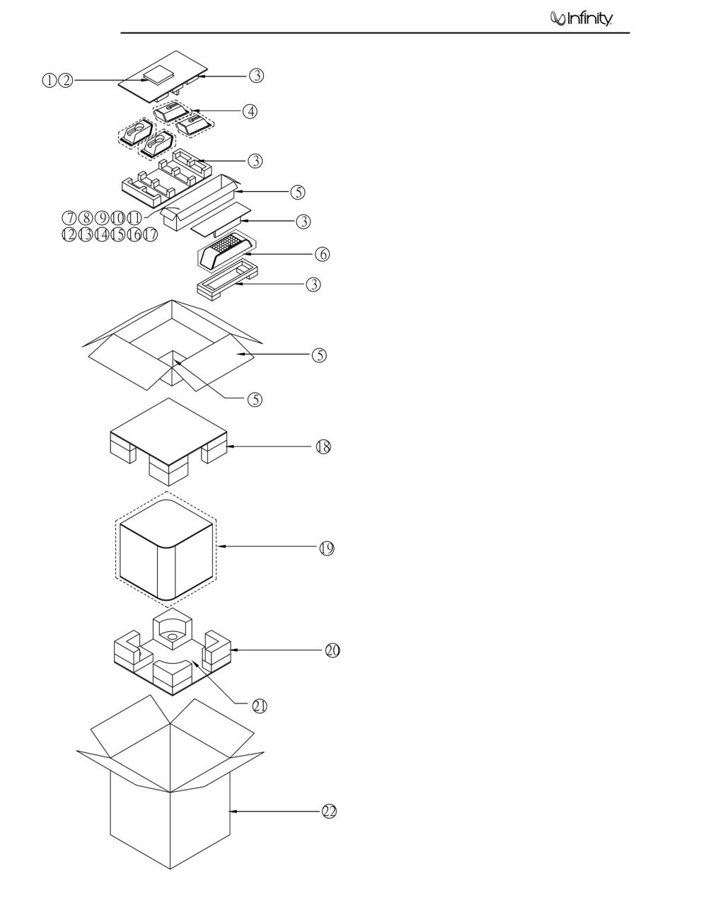
TSS-500 PACKING/ACCESSORIES
Item # |
Description |
Part Number |
Qty |
|
|
|
|
1 |
Warranty Card |
405-000-05110-E |
1 |
2 |
Owner’s Manual |
406-000-05307-E |
1 |
3 |
Packing |
Not for Sale |
1 |
4 |
Packing Bag |
Not for Sale |
4 |
5 |
Inner Carton |
Not for Sale |
1 |
6 |
Packing Bag |
Not for Sale |
1 |
7 |
Nut wrench (metal bar) |
399-FE-00630-E |
1 |
8 |
15’ RCA cable |
370-000-00273-E |
1 |
9 |
Rubber feet for stands (Platinum) |
373-000-05051-E |
1 |
|
Rubber feet for stands (Charcoal) |
373-000-05050-E |
1 |
10 |
Screw for stands (5) ¼ x 20 x1” (Platinum) |
371-000-05108-E |
1 |
|
Screw for stands (5) ¼ x 20 x1” (Charcoal) |
371-000-05114-E |
1 |
11 |
Wall Bracket ball end (5) (Platinum) |
373-000-05054-E |
1 |
|
Wall Bracket ball end (5) (Charcoal) |
373-000-05055-E |
1 |
12 |
40’ Wire set (2) |
370-000-00276G-E |
2 |
13 |
20’ Wire set (3) |
370-000-00277G-E |
3 |
14 |
Satellite stand (Platinum) |
325-ABS-05126-0VAE |
4 |
|
Satellite stand (Charcoal) |
325-ABS-05127-0BAE |
4 |
15 |
Wall bracket |
398-ABS-00317-0VAE |
5 |
16 |
Center table stand (Platinum) |
325-ABS-05127-0VAE |
1 |
|
Center table stand (Charcoal) |
325-ABS-05126-0BAE |
1 |
17 |
Rubber gasket for stand |
336-RUB-05200-0VAE |
1 |
18 |
Subwoofer Top Packing |
431-000-05639-E |
1 |
19 |
Packing Bag |
Not for Sale |
1 |
20 |
Subwoofer Btm Packing |
431-000-05640-E |
1 |
21 |
Desiccant |
Not for Sale |
3 |
22 |
Outer Carton (Platinum) |
402-000-05533-E |
1 |
|
Outer Carton (Charcoal) |
402-000-05534-E |
1 |
2

TSS-Sub500
TSS-Sub500 |
100W Powered Sub/ Plate Amp |
|
|
||
|
|
|
|
|
|
|
|
|
|
|
|
LINE VOLTAGE |
Yes/No |
Hi/Lo Line |
Unit |
Notes |
|
US 120VAC/60Hz |
Yes |
108-132 |
Vrms |
Normal Operation |
|
Europe 220-240VAC, 50-60Hz |
Yes |
220-240 |
Vrms |
Normal Operation |
|
|
|
|
|
|
|
Parameter |
Specification |
Unit |
QA Test Limits |
Conditions |
Notes |
Amp Section |
|
|
|
|
|
Type (Class AB, D, other) |
AB |
AB |
n/a |
120V Model |
External Sink required |
Type (Class AB, D, other) |
G |
G |
n/a |
230V Model |
External Sink required |
Load Impedance (speaker) |
4 |
Ohms |
n/a |
Nominal |
|
Rated Output Power |
100 |
Watts |
95 |
Single input driven |
|
THD@ Rated Power |
0.5 |
% |
1 |
22K filter |
|
THD @ 1 Watt |
0.1 |
% |
0.5 |
22K filter |
|
DC Offset |
10 |
mV-DC |
50 |
@ Speaker Output |
|
|
|
|
|
|
Measured at amplifier board speaker output |
Damping factor |
>100 |
DF |
100 |
50Hz, 4 Ohms load |
terminals, Output power 90 Watts |
|
|
|
|
|
|
Input Sensitivity |
|
|
|
|
|
Input Frequency |
50 |
Hz |
50 |
Nominal Freq. |
|
Line Input (L&R) |
13.8 |
mVrms |
±2dB |
To 1 Watt |
Single input driven, AP Zo=600 Ohms |
LFE Input |
8.62 |
mVrms |
±2dB |
To 1 Watt |
LFE input driven only, AP Zo=600 Ohms |
|
|
|
|
|
|
Signal to Noise |
|
|
|
|
|
SNR-A-Weighted |
100 |
dBA |
85 |
rel. to rated power |
A-Weighting filter |
SNR-unweighted |
80 |
dBr |
80 |
rel. to rated power |
22K filter |
SNR @ 1W-unweighted |
60 |
dBr |
60 |
rel. to 1W Output |
22K filter |
|
|
|
|
Volume @max, using RMS reading |
|
Residual Noise Floor |
1 |
mVrms |
2 |
DMM/VOM (or A/P) |
|
|
|
|
|
Volume @max, w/ A/P Swept Bandpass |
|
Residual Noise Floor |
1 |
mVrms(max) |
2 |
Measurement (Line freq.+ harmonics) |
|
|
|
|
|
|
|
Input Impedance |
|
|
|
|
|
Line input L&R , LFE |
>10 |
K ohms |
n/a |
Nominal |
|
|
|
|
|
|
|
Filters |
|
|
|
|
|
Low Pass (fixed or variable) |
4th order fix |
-- |
±2dB |
|
|
Subsonic filter (HPF) |
2nd order |
Hz |
±2dB |
|
|
|
|
|
|
|
|
Limiter (yes/no) |
YES |
-- |
Functional |
|
|
THD at Max. Output Power |
1 |
% |
Functional |
|
|
|
|
|
|
|
|
Features |
|
|
|
|
|
LFE Input |
YES |
|
Functional |
|
|
Volume pot Taper (lin/log) |
LOG |
-- |
Functional |
|
|
ATO |
YES |
|
Functional |
|
|
|
|
|
|
|
|
Input Configuration |
|
|
|
|
|
Line In (L,R) |
L ,R |
-- |
Functional |
|
RCA inputs |
Line level in LFE |
LFE |
|
Functional |
|
|
|
|
|
|
|
|
Signal Sensing (ATO) |
|
|
|
|
|
Auto-Turn-On (yes/no) |
YES |
-- |
Functional |
|
|
ATO Input Frequency |
50 |
Hz |
Functional |
|
|
|
|
|
|
2mV@50Hz into Line Input w/ 1 ch. |
|
ATO Level |
2 |
mV |
Functional |
driven |
|
|
|
|
|
Amp connected and AC on, then input |
|
ATO Turn-on time |
5 |
ms |
Functional |
signal applied |
|
Auto Mute/ Turn-OFF Time |
10 |
minutes |
Functional |
T before muting, after signal is removed |
Auto turn of time (T) must be 5 > T <15 |
|
|
|
|
|
|
Power on Delay time |
3 |
sec. |
Functional |
AC Power Applied |
|
|
|
|
|
|
|
Transients/Pops |
|
|
|
|
|
ATO Transient |
5 |
mV-peak |
10 |
Speaker Outputs |
|
Turn-on Transient |
50 |
mV-peak |
100 |
Speaker Output |
AC Line cycled from OFF to ON |
Turn-off Transient |
50 |
mV-peak |
100 |
Speaker Output |
AC Line cycled from ON to OFF |
|
|
|
|
|
|
Efficiency |
|
|
|
|
|
|
|
|
|
|
Maximum allowable input power under |
|
|
|
|
|
nominal Input voltage and frequency, HOT |
Stand-by Input Power |
12 |
Watts |
15 |
@ nom. line voltage |
or COLD operation. |
Power Cons.@rated power |
195 |
Watts |
210 |
@ nom. line voltage |
100 Watts @ 4 Ohms nominal line voltage |
|
|
|
|
|
|
3

TSS-Sub500
|
|
|
|
|
|
Parameter |
Specification |
Unit |
QA Test Limits |
Conditions |
Notes |
|
|
|
|
|
|
|
|
|
|
|
|
Protection |
|
|
|
|
|
Short Circuit Protection |
YES |
-- |
Functional |
Direct short at output |
|
|
|
|
|
|
Temperature rise should not exceed 35K |
Thermal Protection |
65 deg. C |
-- |
Functional |
@1/8 max unclipped Power |
rise |
DC Offset Protection |
YES |
-- |
Functional |
DC present at Speaker Out leads |
Relay or crowbar (for driver/fire protection) |
Line Fuse Rating |
|
|
|
|
External fuse with UL/SEMKO rated holder |
|
|
|
|
Type-T or Slo Blo, Fuse Markings T2.5A, |
|
120 VAC |
2.5 |
Amps |
|
250V |
|
|
|
|
|
Type-T, Low breaking capacity, Fuse |
|
230 VAC |
1.25 |
Amps |
|
markings T1.25AL, 250V |
|
4
TSS-Sub500
|
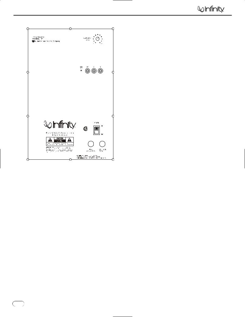
SUBWOOFER CONTROLS |
¡ |
Rear Panel |
A Few Suggestions
We recommend that you do not operate your speakers or ™ £ subwoofer with the bass, treble and loudness controls set to
full boost.This will place undue strain on your electronics and speakers and could damage them.
The volume control setting on your processor/preamp or receiver is not a specific indication of the overall loudness level of the speakers.The only important consideration is the loudness level at which the system can be played, regardless of where the volume control is set.
Always turn down the volume control setting on your processor/ preamp or receiver when changing a cassette or CD, or switching inputs to AM or FM operation. Excessively loud transients (clicks or popping sounds) can damage the satellite speakers and possibly the subwoofer.
TSS |
500 |
CSA 22-2 NO.1 |
¢ |
Important! |
|
|
R |
|
|
|
|
NRTL/C |
|
|
|
|
UL 1492 |
|
|
Whenever changing cables, pulling plugs, etc., ALWAYS TURN OFF
ALL EQUIPMENT, including the subwoofer.
¡ Subwoofer Level Control
™ LFE Input
£ Line-Level Inputs
¢ Power Switch
5 |
TSS-500 |
5 |
|
|
TSS-Sub500
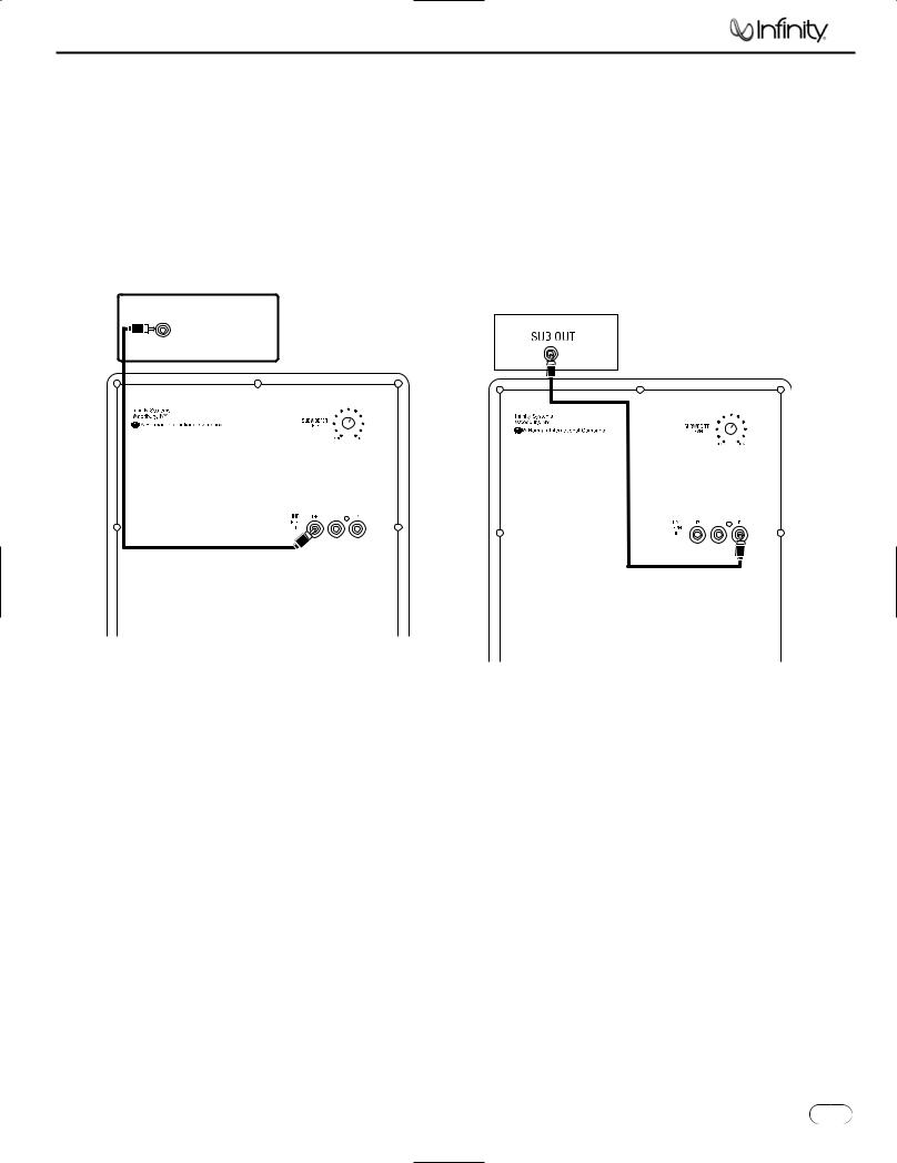
SUBWOOFER CONNECTIONS
If you have a Dolby® Digital or DTS® receiver/ processor with a low-frequency-effects (LFE) or subwoofer output:
15' (4.6m) subwoofer cable included
SUBWOOFER OR |
LFE OUTPUT |
If your receiver/processor does not contain a Dolby Digital or DTS processor but has a subwoofer output:
RECEIVE ROCESSOR
15' (4.6m) subwoofer cable included
NOTE: If your receiver/processor has only one sub out, you may use either the L or R input.
6 |
TSS-500 |
6 |
|
|

TSS-Sub500
OPERATION
Surround Modes
When using the TSS-500 in a Dolby Digital or DTS home theater system, make sure all speakers are set to “Small”. When using the system in a Dolby Pro Logic® home theater system, make sure the receiver’s center channel mode is set to “Normal”.
Some Dolby Digital-equipped receivers/processors offer different setup options for each source or surround mode (e.g., CD-stereo, videotape, Dolby Digital, Pro Logic). In each case, follow your equipment’s instructions to ensure that the subwoofer output is turned on and that the speakers are set to “Small” in each mode.
If your receiver has adjustable crossover settings, we recommend the subwoofer crossover be set between 100Hz and 120Hz.
Power On
Plug your subwoofer’s AC cord into a wall outlet. Do not use the outlets on the back of the receiver.
Initially set the Subwoofer Level Control 1 to the“MIN” position.
Turn on the subwoofer by pressing the Power Switch 4 on the rear panel.
Turn on your entire audio system and start a CD or movie soundtrack at a moderate level.
Auto On/Standby
With the Power Switch 4 in the ON position, the LED on the back will remain lit in green or red to indicate the ON/STANDBY mode of the subwoofer.
RED = STANDBY (No signal detected, Amp Off)
GREEN = ON (Signal detected, Amp On)
The subwoofer will automatically enter the Standby mode after approximately 10 minutes when no signal is detected from your system.The subwoofer will then power ON instantly when a signal is detected. During periods of normal use, the Power Switch 4 can be left on. You may turn off the Power Switch 4 for extended periods of nonoperation, e.g., when you are away on vacation.
Adjust Level
Turn the Subwoofer Level Control 1 up about halfway. If no sound emanates from the subwoofer, check the AC-line cord and input cables. Are the connectors on the cables making proper contact? Is the AC plug connected to a “live” receptacle? Has the Power Switch 4 been pressed to the “On” position? Once you have confirmed that the subwoofer is active, proceed by playing a CD or DVD. Use a selection that has ample bass information.
Set the overall volume control of the receiver/processor to a comfortable level. Adjust the Subwoofer Level Control 1 until you obtain a pleasing blend of bass. Bass response should not overpower the room but rather be adjusted so there is
a harmonious blend across the entire musical range. Many users have a tendency to set the subwoofer volume too loud, adhering to the belief that a subwoofer is there to produce lots of bass.This is not entirely true. A subwoofer is there to
7 |
TSS-500 |
7 |
|
|
enhance bass, extending the response of the entire system so the bass can be felt as well as heard. However, overall balance must be maintained or the music will not sound natural. An experienced listener will set the volume of the subwoofer so its impact on bass response is always there but never obtrusive.
Final Positioning
After correctly connecting the TSS-500 system and verifying that both the subwoofer and all satellite speakers are playing, it is time to optimize the system for your particular listening room. Earlier, you placed the subwoofer in its general location. Finding the exact location for optimum performance sometimes only involves moving the speakers up to a few inches in any direction. We urge you, therefore, to experiment with placement, if possible, until your speakers deliver their full potential.
MAINTENANCE AND SERVICE
The satellite and subwoofer enclosures may be cleaned using a soft cloth to remove fingerprints or to wipe off dust.
All wiring connections should be inspected and cleaned or remade periodically.The frequency of maintenance depends on the metals involved in the connections, atmospheric conditions and other factors, but once per year is the minimum.
If a problem occurs, make sure that all connections are properly made and clean. If a problem exists in one loudspeaker, reverse the connection wires to the left and right system. If the problem remains in the same speaker, then the fault is with the loudspeaker. If the problem appears in the opposite speaker, the cause is in another component or cable. In the event that your TSS-500 ever needs service, contact your local Infinity dealer or visit www.infinitysystems.com for a service center near you.

TSS-Sub500
8
 Loading...