


Infinity RA-7502 Service manual
RA 7502
2 CHANNEL
POWER AMPLIFIER
TECHNICAL MANUAL
.infinitysystem.com
www
c 200 harman consumer international
Print in - 10/2000
Infinity

2 Channel Power Amplifier
Controls and connections
Specifications .........................................................1
Features .................................................................2
Test Conditions and Notes .......................................2
Controls and Connections ........................................3
Typical System Configuration (Wiring) ........................4
Printed Circuit Boards (Top View)...............................5
Number of Channels . . . . . . . . . . . . . . . . . . . . . .
Power Output max . . . . . . . . . . . . . . . . . . . . . . . .
RMS Bridged Power Output ,4 Ohm . . . . . . . . . . . . . . . . . . . . . ..
RMS Power Output,2 Ohm . . . . . . . . . . . . . . . . . . . . . . . . . .
RMS Power Output,4 Ohm . . . . . . . . . . . . . . . . . . . . . . . . . .
THD@Rated Output. . . .. . . . . . . . . . . . . . . . . . . . . . . . . . . .
SNR (A - weighted) . . . . . . . . . . . . . . . . . . . . . . . . . . . . .
Frequency response . . . . . . . . . . . . . . . . . . . . . . . . . . . . .
Parts Lists......................................................6~7
Block Diagrams...................................................8
Packaging Exploded View.....................................9
Integrated Circuit Diagrams.................................10
Transistor Diagrams......................................11~12
Schematic Diagrams................... ..................13~14
Amplifier Exploded View.....................................15
SPECIFICATIONS
2
300W
220W
2 x 110W
2 x 75W
0.10%
>92dB
10Hz-40kHz
Active crossover(cont.var.) . . . . . . . . . . . . . . . . .
Crossover settings . . . . . . . . . . . . . . . . . . . . .
Crossover slope . . . . . . . . . . . . . . . . . . . . . . .
Input sensitivity. . . . . . . . . . .
. . . . . . . . . . . . . . .
Bass Boost . . . . . . . . . . . . . . . . . . . .
External Dimensions (Inches)
Length . . . . . . . . . . . . . . . . . . . . . . . . . . .
Width . . . . . . . . . . . . . . . . . . . . . . . . . . .
Depth . . . . . . . . . . . . . . . . . . . . . . . . . . .
External Dimensions (mms)
Length . . . . . . . . . . . . . . . . . . . . . . . . . . .
Width . . . . . . . . . . . . . . . . . . . . . . . . . . .
Depth . . . . . . . . . . . . . . . . . . . . . . . . . . .
30-320Hz
LP/HP/OFF
12dB/oct
100mV-4V
+6dB@45Hz
13 3/8
9 3/8
2 1/16
340
238
52
1

2 Channel Power Amplifier
Features
RCA-jacks, Speaker-and power terminals gold-plated
2 ohm stability(stereo mode)
Bridging capability(min.4 ohm)
Tri-mode operation(min.4 ohm)
Protection circuitry thermal-and electrical overload.short-circuit.DC-offset
HPF variable high pass filter(HPF)30-320Hz.12dB/oct.
LPF variable low pass filter(LPF)30-320Hz.12dB/oct.
+6dB(at 45Hz)Bass boost
Test Conditions and Notes
All tests to be done, unless otherwise specified, from 30Hz to 320Hz at 14.4V DC into 2 ohm loads and adjust
the units gain so that with a .100 volt input signal the unit is at its maximum rated output. All measurements
will be done using an Audio precision system one and the supply voltage.
An A+ line voltage of 14.4V DC shall be applied to the unit under test for all measurements unless otherwise
specified. The voltage applied to the unit shall be measured at the power connection on the Amplifier.
Signal Source
Unless otherwise specified, all tests shall be conducted with the Audio Signal Generator output configured to
be balanced, less than or equal to 50 ohm source impedance, and floating. The signal source "GND" shall be
connected to the Amplifier PWR GND at the Amplifier.
Output Load
Unless otherwise specified, all tests shall be conducted with 2 ohm resistive loads having less than 0.1%
reactive components at any frequency below 1Kz. Each resistor shall have a value that remains within 0.1%
while dissipating the rated output of the unit under test.
Power Indicator LED steadily illuminates for normal operation.
2
2 Channel Power Amplifier
Controls and Connections
2
11
3
4
5
8
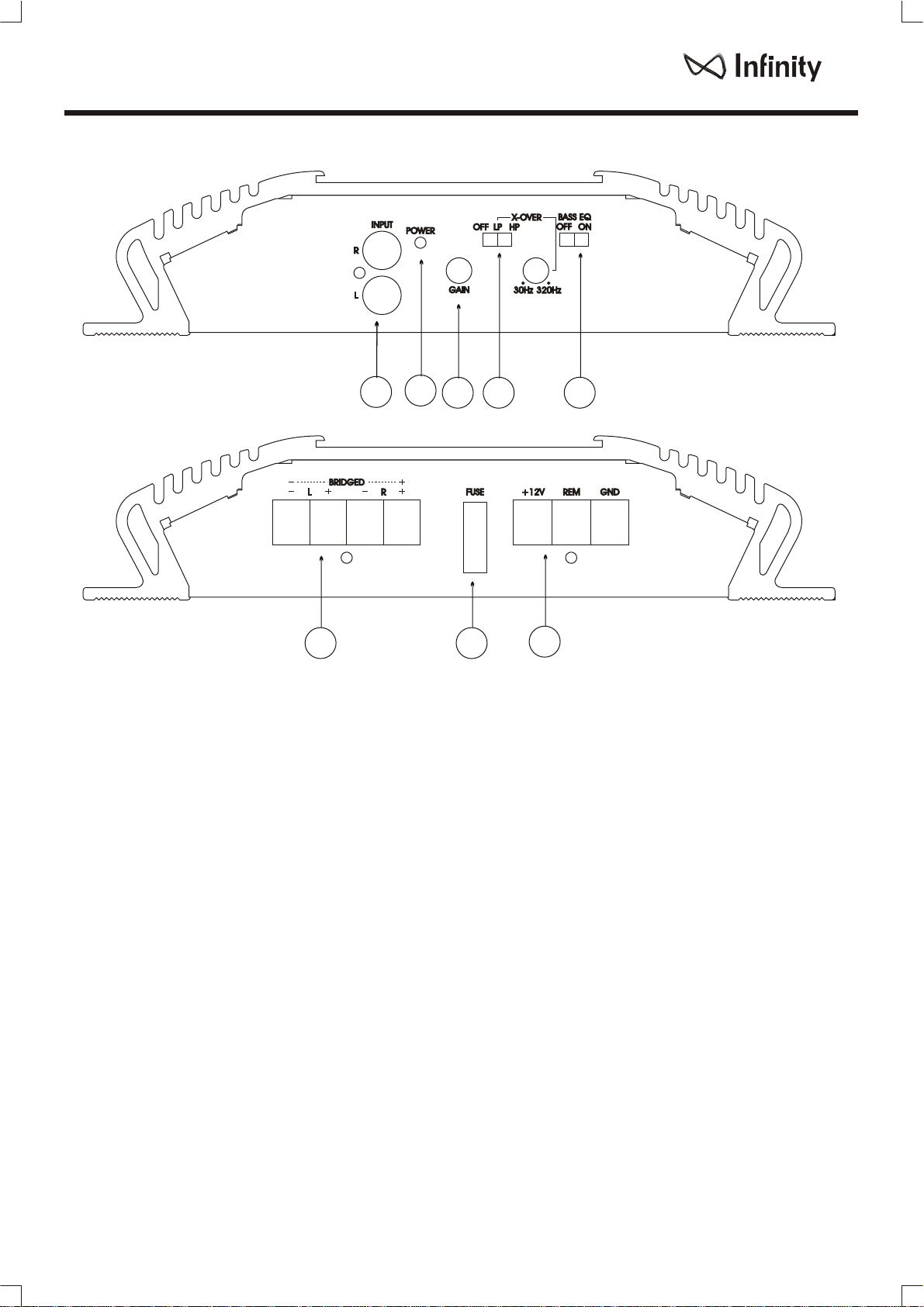
Controls and Connections
1. Low INPUT (RCA JACK TYPE)
- Connection to line of level output from the
source unint
2. Power Indicator
3. Input-sensitivity level coltrol
4. Low/High pass filter which caN be set at
any frequenccy between 30Hz and 320Hz(adjustable)
7
5. +6dB(at45Hz)Bass boost
6.Power Connector-Connection +12V+ for,
GND and REM in or out.
7.Fuse - 32V25A attached type
8. Output Connector - connect a wire between
the output terminal on the amp and Speakers
(each channels)
6
3
 Loading...