


Infinity BU-80, BU-80-E, HTS-10 Service manual

BU80
BU80E
HTS-10
POWERED SUBWOOFER
SERVICE MANUAL
Infinity Systems, Inc.
250 Crossways Park Dr.
Woodbury, New York 11797 Rev H 11/2001

Amplifier/Subwoofer BU-80/BU80E/HTS-10
2
SAFETY INFORMATION/VERSION DIFFERENCES
Warning
Any person performing service of this unit will be exposed
to hazardous voltages and the risk of electric shock. It is
assumed that any person who removes the amplifier from
this cabinet has been properly trained in protecting against
avoidable injury and shock. Therefore, any service
procedures are to be performed by qualified service
personal ONLY!
Caution
This unit does not have a power switch. Hazardous
voltages are present within the unit whenever it is
plugged in.
Before the amplifier is plugged in, be sure its rated voltage
corresponds to the voltage of the AC power source to be
used. Incorrect voltage could cause damage to the amplifier
when the AC power cord is plugged in. Do not exceed rated
voltage by more than 10%: operation below 90% of rated
voltage will cause poor performance or may shut the unit
off.
List of Safety Components Requiring
Exact Replacements
F1 ** Fuse SLO BLO 0.50A or 1.0A 250V
5 x 20mm.UL approved
See Bulletin (INF2000-02) page 16.
PWRCORD SPT-2 or better with polarized plug, UL
approved wired with the hot side to fused
side. Use with factory replacement panel
strain relief only.
T1 ** Transformer. Use only factory
Replacement.
DBR or D001 Bridge diode. Use only factory
replacement.
C1, 2 3300uF, 50V electrolytic filter caps. Be
sure replacement part is at least the same
working voltage and capacitance rating.
Also the lead spacing is important.
Incorrect spacing may cause premature
failure due to internal cabinet pressure
and vibration.
C6 * 10uF 50V electrolytic radial (BU80 and
HTS-10 version “A”,”B” only)
S53AMI Power output module. Use only factory
or CON101 replacement
Faceplate Use only factory replacement
Air leak cover Use only factory replacement
CMC1 Use only factory replacement
L1 Use only factory replacement
Fuse PCB Use only factory replacement
Main PCB Use only factory replacement
R29 470 ohm 1/4W METAL OXIDE, non
flammable
Leakage/Resistance Check
Before returning the unit to the customer, perform a leakage
or resistance test as follows:
Leakage Current. Note there is no power switch on this unit.
When the power plug is plugged in, the unit is live. Connect
the unit to its rated power source. Using an ammeter,
measure the current between the neutral side of the AC
supply and chassis ground of the unit under test. if leakage
current exceeds 0.5mA, the unit is defective. Reverse the
polarity of the AC supply and repeat.
Resistance. Measure the resistance from either side of the
line cord to chassis ground. If it is less than 500k ohms, the
unit is defective.
WARNING! DO NOT return the unit to the customer if it
fails one of these tests until the problem is located and
corrected.
* See Service Bulletin (INF2000-01) page 15.
** See Service Bulletin (INF2000-02) page 16.
Rev A version of the BU-80/HTS-10 subwoofer uses
the following SAFETY PARTS:
#80103 - T1 Power Transformer #4300
#80104 - F1 Line fuse 0.5A 250V T type slo-blo
Rev B version of the BU-80/HTS-10 subwoofer uses the
following SAFETY PARTS:
#80127 - T1 Power Transformer #4300F
#80111 - F1 Line fuse 1.0A 250V T type slo-blo
Either Rev A or Rev B can be identified by:
The correct fuse rating will be printed on the amplifier
label, also:
BU-80: Rev A version
serial #AM0011-29474 and below;
Rev B version serial #AM0011-29475 and
above.
HTS-10: Rev A version serial #AM0011-07400
and below;
Rev B version serial #AM0011-07401 and
above.
HTS-10 subwoofer only
There is a third version, “C”, with minor internal
differences.
Data for this ver s ion is inc luded, and differences ar e
noted in the manual.
Units can be identif ied for service as follows:
Amplifier fac eplate says “Made in Canada” on the “B ”
version.
Amplifier fac eplate says “Made in China” on the “C”
version.
BU80E = HTS-10 version, “C”

TABLE OF CONTENTS
Amplifier/Subwoofer
BU-80/BU80E/HTS-10
3
SAFETY INFORMATION/VERSION DIFFERENCES....2
GENERAL SPECIFICATIONS........................................3
DETAILED SPECIFICATIONS........................................4
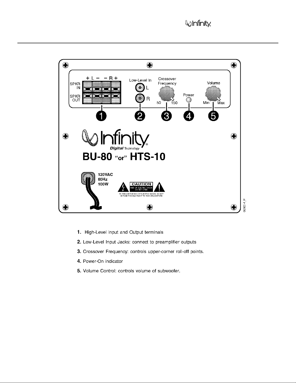
CONTROLS AND THEIR FUNCTION............................5
BU80/BU80E/HTS-10 CONNECTIONS ........................6
OPERATION ................................................................10
BU80/BU80E/HTS-10 TEST SET UP PROCEDURE...11
BU-80/HTS-10 POWER AMP TEST PROCEDURE
FLOW CHART..............................................................13
SERVICE BULLETIN INF9902 - APRIL 1999 ..............14
SERVICE BULLETIN INF2000-01rev2 -
FEBRUARY 2001 ........................................................15
SERVICE BULLETIN INF2000-02 - MARCH ..............16
TECH TIPS ..................................................................17
BU80/BU80E/HTS-10 AMPLIFIER ASSEMBLY
EXPLODED VIEW........................................................18
BU80/BU80E/HTS-10 PACKING & CABINET PARTS...20
BU-80/HTS-10 rev. A, B PCB (version 5) ....................21
BU-80/HTS-10 rev A, B PCB (version 5.1) ..................22
BU-80/HTS-10 rev A, B ELECTRICAL PARTS LIST....23
BU80/BU80E/HTS-10 INTEGRATED CIRCUIT/
TRANSISTORS DIAGRAM ..........................................24
BU-80/HTS-10 rev A, B SCHEMATIC 1 of 2 ................25
BU-80/HTS-10 rev A, B SCHEMATIC 2 of 2................26
BU80E/HTS-10 REV C
ELECTRICAL PARTS LIST ...27
BU80E/HTS-10 REV C CIRCUIT BOARDS ...............29
BU80E/HTS-10 REV C SCHEMATIC .........................32
BU80E/HTS-10 REV C POWER AMP
MODULE SCHEMATIC ................................................33
GENERAL SPECIFICATIONS
Frequency Response (± 3 db)..............45Hz - 150Hz
Output (RMS) ......................................75W
Driver....................................................8” Woofer
Crossover Frequency ..........................50Hz ~ 150Hz (continuously variable)
Dimensions (H x W x D) ......................11½” (29.2cm) x 11½” (29.2cm) x 11½” (29.2cm)
Add 1¾” (4.5cm) for feet.
Weight ..................................................26 lbs/11.8 kg,
Refinements may be made on occasion to existing products without notice,
but will always meet of exceed original specifications unless otherwise stated.
IMPORTANT SERVICE NOTES: When testing the BU Series amplifier, a load must always
be connected to the output terminals, whether the woofer, or a 4 to 8 ohm resistive load.
All AC powered test instruments (meters, oscilloscopes, etc.) must have a floating
ground, i.e. be connected to an isolation transformer.
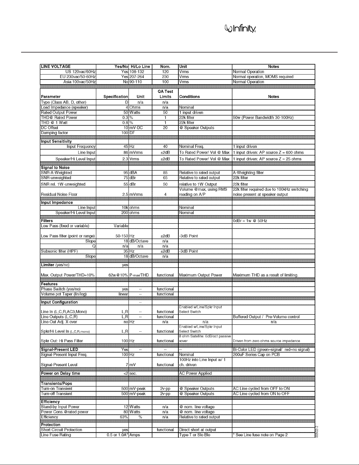
DETAILED SPECIFICATIONS
Amplifier/Subwoofer
BU-80/BU80E/HTS-10
4
Amplifier/Subwoofer
BU-80/BU80E/HTS-10
5
CONTROLS AND THEIR FUNCTION
Amplifier/Subwoofer BU-80/BU80E/HTS-10
6
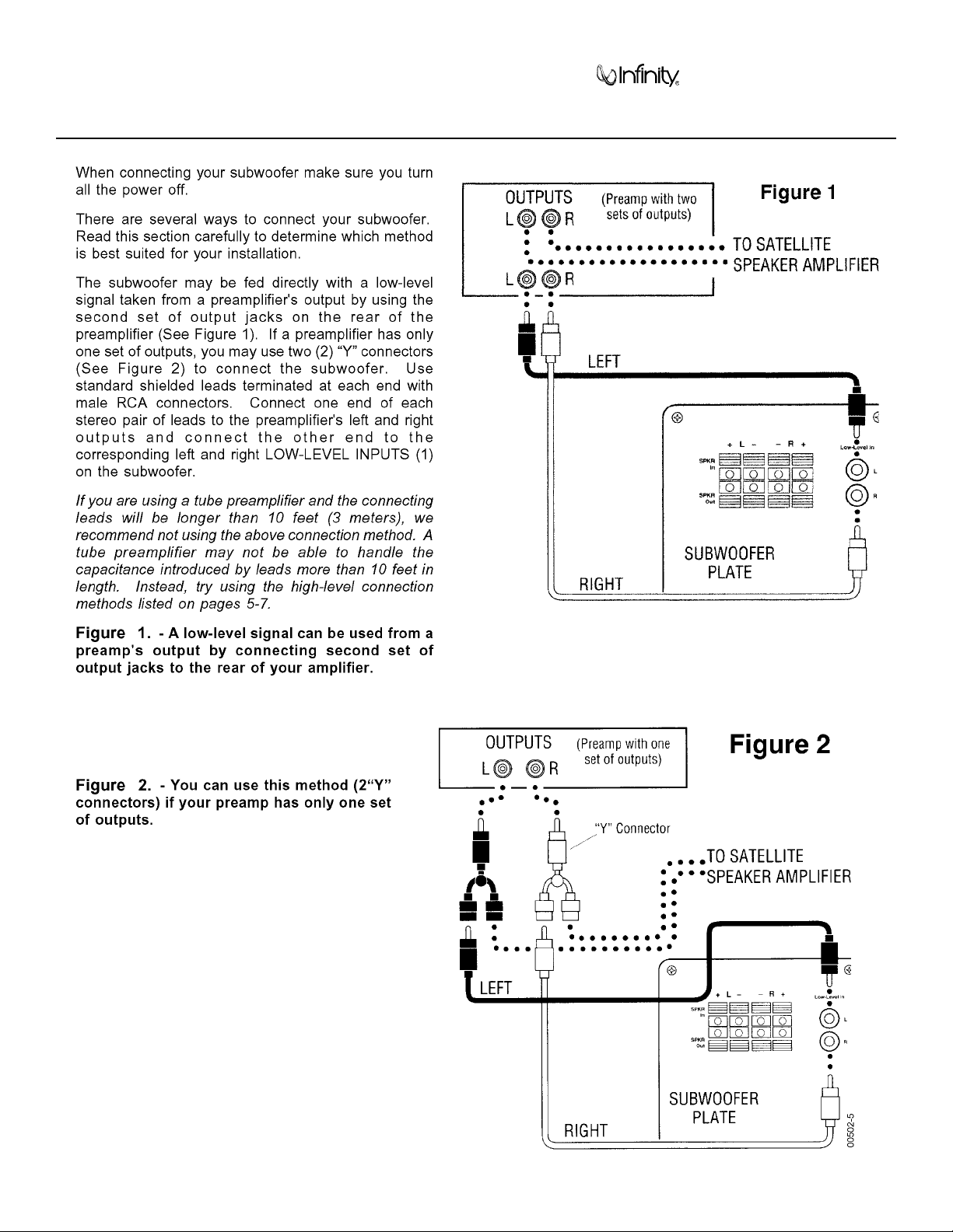
BU-80/BU80E/HTS-10 CONNECTIONS
Amplifier/Subwoofer BU-80/BU80E/HTS-10
7
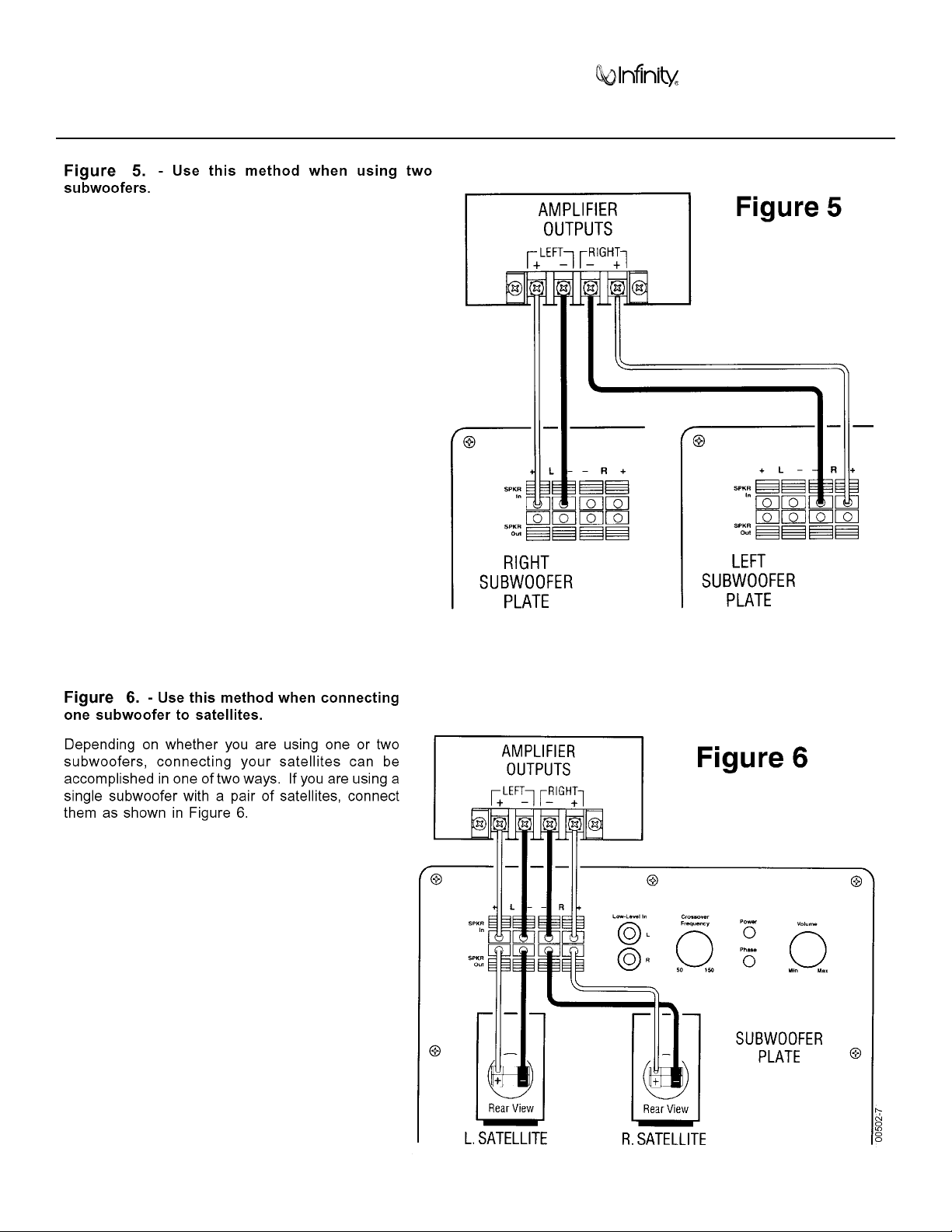
BU-80/BU80E/HTS-10 CONNECTIONS (Cont.)
Amplifier/Subwoofer BU-80/BU80E/HTS-10
8
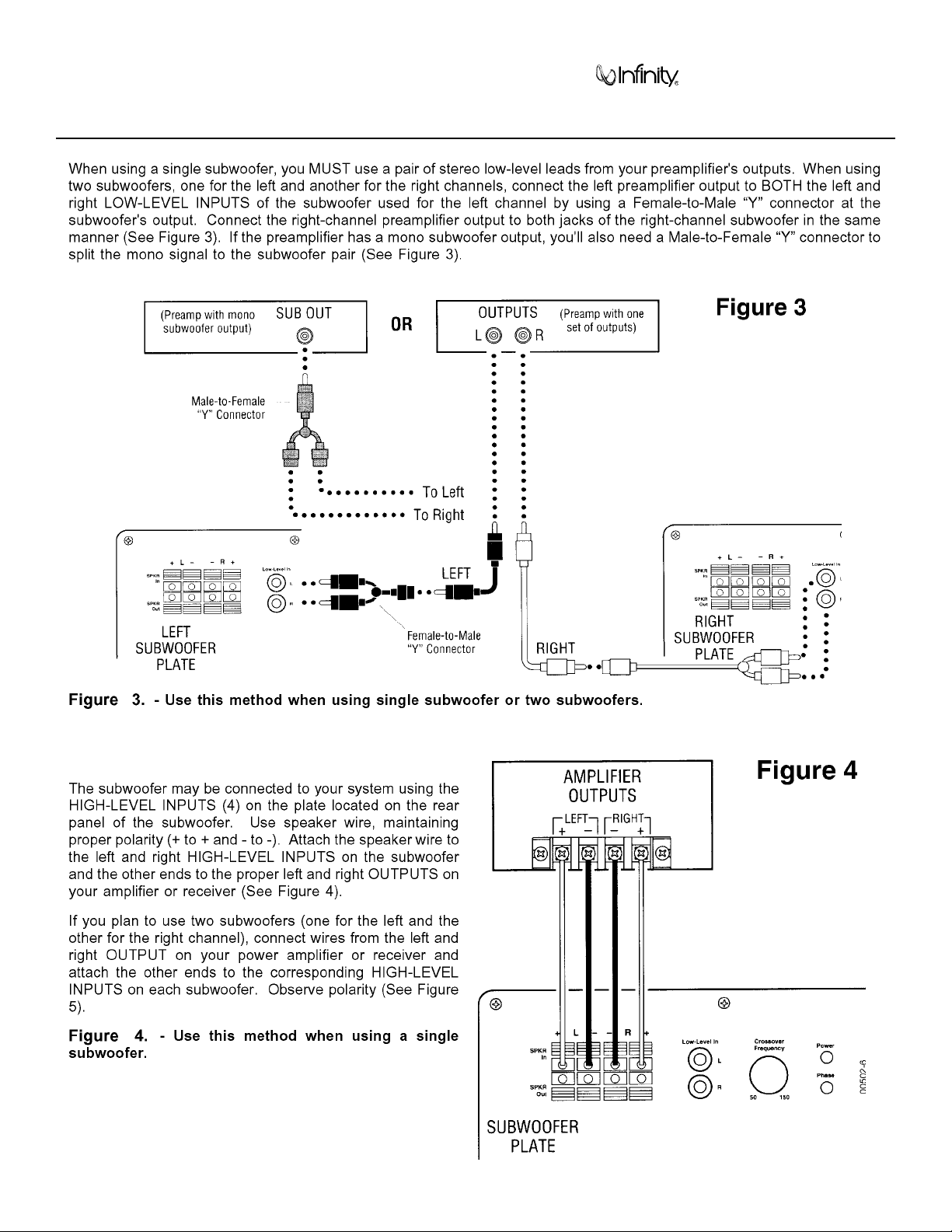
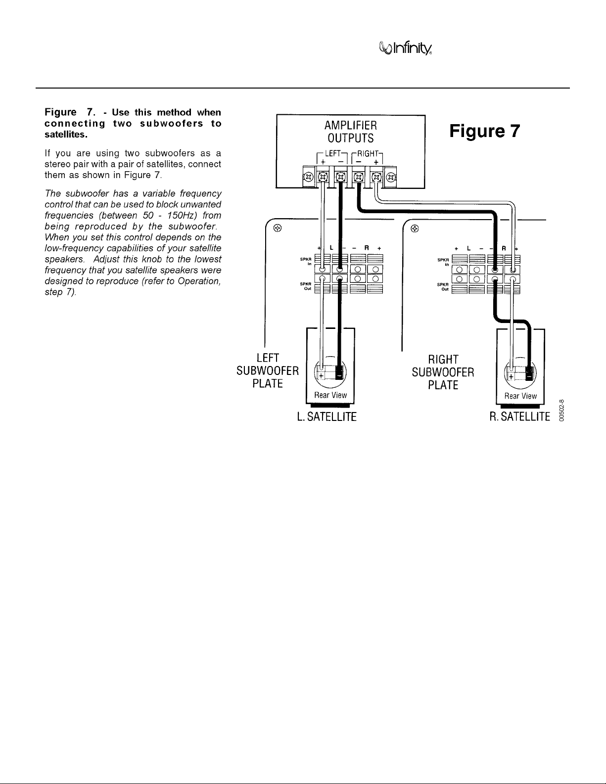
BU-80/BU80E/HTS-10 CONNECTIONS (Cont.)
Amplifier/Subwoofer BU-80/BU80E/HTS-10
9
BU-80/BU80E/HTS-10 CONNECTIONS (Cont.)
Amplifier/Subwoofer BU-80/BU80E/HTS-10
10
OPERATION
Amplifier/Subwoofer BU-80/BU80E/HTS-10
11
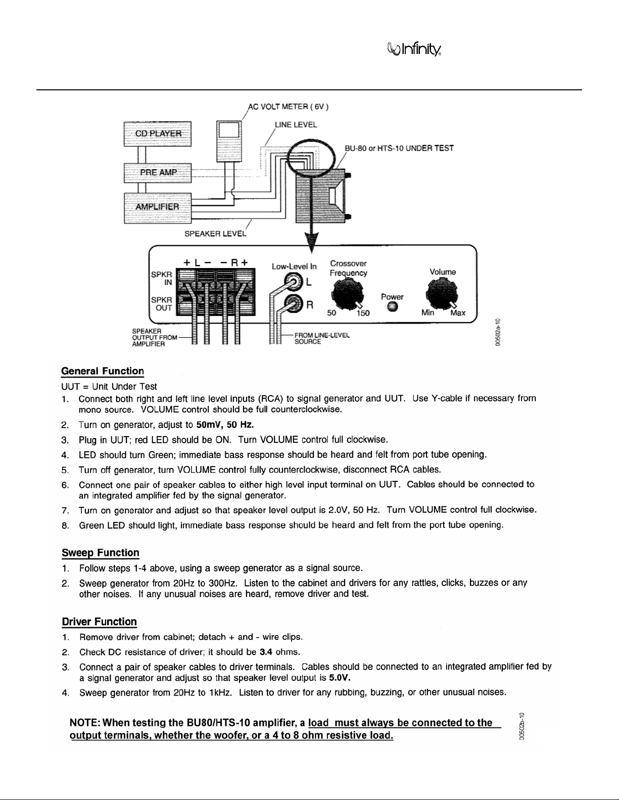
BU-80/BU80E/HTS-10 TEST SET UP AND PROCEDURE
 Loading...