


Infinity Kappa 255-A Service manual

Kappa 255a
Automotive Amplifier
SERVICE MANUAL
Infinity Systems Incorporated
250 Crossways Park Dr.
Woodbury, New York 11797
Rev2 10/2004

Kappa 255a
- CONTENTS -
SPECIFICATIONS ……..…………………………………………………………..2
FEATURES ..……………………………….……………….……………….…...…3
APPLICATIONS (SET-UP GUIDE) ………………..……..……………………….4
PRECAUTION AND NOTES..…..………………….….…………………………..6
INSTALLATION ….………..…………..…………….……………………………..7
TROUBLESHOOTING ….………..………………….……………………………..9
SERVICE BULLETIN #INF9701 ….…………...…………………..……………..10
SERVICE BULLETIN #INF2001-02 ….…………………………………………..11
EXPLODED VIEW….………..…………………………………………………….13
PCB DRAWINGS ….………..……………………………………………………..14
BLOCK DIAGRAMS………...……………….……………….…………..….…….20
ELECTRICAL PARTS LIST ..……………….……………….…………..….…….22
SEMICONDUCTOR PINOUTS………………..……..…………………..……….30
SCHEMATICS …………..……………………..…….…….….………..………….31
REVISIONS ……………..……………………..…….…….….………..………….43
Occasional refinements may be made to existing products without notice but will always meet or exceed original specifications
unless otherwise stated
1

2
Kappa 255a
KAPPA 255A SPECIFICATIONS
POWER
4 OHM 4 x 50 and 1 x 200 watts
2 OHM 4 x 75 and 1 x 300 watts
BRIDGE 4 OHM 2 x 150 and 1 x 200 watts
1 OHM STABLE PROTECTION
FREQUENCY RESPONSE
EQUALIZATION
FIXED AT 40Hz Q=1 +11dB
CROSSOVER
FLAT/LOW/HIGH PASS SWITCH 2
DECADE SWITCH (40-320 & 250-2KHz)
VAR. CONTROL 2
SLOPE 12
INPUT SENSITIVITY
FULL DIFFERENTIAL INPUT
POWER FUSE
THD + NOISE
4 ohm 0.05%
2 ohm 0.10%
bridge 4 ohm 0.10%
SIGNAL TO NOISE
CHANNEL SEPARATION
DAMPING FACTOR
TURN ON TIME
DC OFFSET
OPERATING VOLTAGE
REMOTE ON CURRENT
QUIESCENT CURRENT
MAX CURRENT
PROTECTION auto reset
spkr short Yes
spkr to ground Yes
thermal Yes
over voltage 18vdc
under voltage 8vdc
DIMENSIONS 23 x 2 3 /16 x 8 1 /2 in. (W x H x L)
20-20KHz (+0 -3dB)
SEE CHART BELOW
250 mV ~ 9 V
>100K IMP
40A X 2 (ATC)
>95dB (A Weighted Referenced to Full Power)
>50dB (100 TO 20KHz)
>204
3 SEC
<50 mv
10 -16vdc
<2ma
<2.5 AMP
80
584.2 x 55.6 x 215.9 mm
All tests to be done from 20 to 20KHz at 14.4 VDC into 4 ohm loads, unless otherwise specified.
Infinity continually strives to update and improve existing products, as well as create new ones. The specifications and
construction details in this and related Infinity publications are therefore subject to change without notice.

3
Kappa 255a
FEATURES
The Kappa 255a is a 5-channel power amplifier that offers full-range stereo and bridged-mono
operation on four analog channels and band-limited mono operation on a class-D channel for
subwoofer applications. The front/rear amplifiers are rated at 50 watts (rms) per channel into a
4-ohm load, while the subwoofer channel is rated at 200 watts (rms) into a 4-ohm load. In
bridged-mono configurations, front and rear amplifiers can deliver up to 150 watts (rms) for the
same load.
· 2-ohm operation, rated at 75 watts (rms) per channel for front and rear channels and 300
watts (rms) for the subwoofer channel
· Bridge/stereo switches for fast system setup
· Built-in 12 dB-per-octave electronic crossovers, variable from 32 to 320 Hz, with an “x15”
front-channel switch (to increase the frequency range from 480 Hz to 4.8 kHz)
· Dynamic Bass Optimizer™ (DBO) 12 dB-per-octave subsonic filter with variable frequency
(20 to 80 Hz) and Q for enhancing subwoofer low frequencies while conserving amplifier
power
· Front and rear channels, individually selectable as highpass, low-pass, or through-pass
· External switch for subwoofer inputs allows direct connection to source units with subwoofer
outputs
· Amplifier input sensitivity controls to match a wide range of input signal levels from 250 mV
to 9 V
· Five protection levels guard against over-voltage, undervoltage, over-power, over-
temperature, and over-current situations
· 2-color LED array indicates green when power is on and orange when protection is
activated
· Industrial-grade, gold-plated, “pre-wire and plug-in” connectors for an easy-to-install high-
quality interface
· Transparent control cover to deter tampering yet provide a clear view of installation settings
· Built-in automotive type fuses to protect the amplifier
· Unibloc™ chassis provides improved heat-sink capacity and exceptional RFI shielding
characteristics
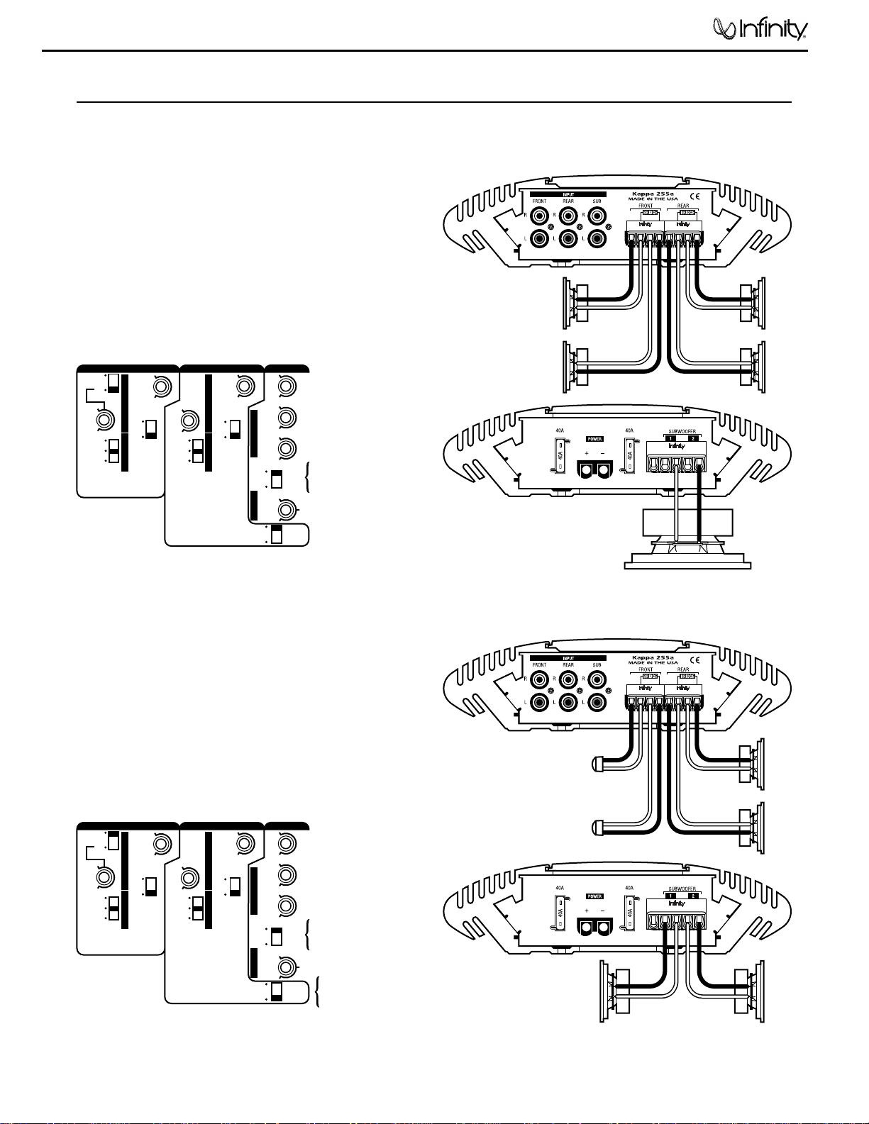
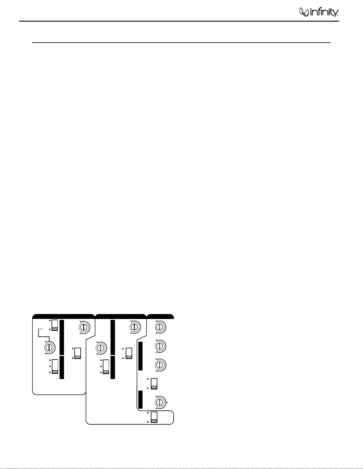
Enclosed are several diagrams to help you plan your own
system installation. Figures 1 through 3 (
on pages 4 and 5)
show how to configure the Kappa 255a to drive front and
rear speakers and a subwoofer, tweeters and midrange
speakers and a pair of subwoofers, and a tweeter/midrange
component set, midbass speakers, and a subwoofer.
For system expansion, see Figure 4 on the next page.
NOTE: For simplicity, Figures 1 through 4 do not show power,
remote, and input connections.
R
– ––
+ ++
L
R
– –
+ +
L
KAPPA 255a
(front panel)
KAPPA 255a
(rear panel)
REM
–
R
+–+
L
SUBWOOFER 1 and 2
are common outputs
and are supplied as
a convenience for
dual-subwoofer
applications
Subwoofer
LR
-
+
+
-
+
-
RRLF
+
-
RF
+
-
ST
BR
HP
FLAT
LP
.25V
9V
G
A
I
N
G
A
I
N
G
A
I
N
M
O
D
E
M
O
D
E
O
U
T
P
U
T
C
R
O
S
S
O
V
E
R
.25V
9V
.25V
9V
80Hz
20Hz
320Hz
32Hz
60
Hz
Q
FREQ
REAR
INPUT
SUB
INPUT
MIN
MAX
320Hz
32Hz
320Hz
32Hz
FRONT LP
EXT
INT
EXT
ST
BR
SUBWOOFER
FRONT REAR
O
U
T
P
U
T
C
R
O
S
S
O
V
E
R
D
B
O
X
O
V
E
R
HP
FLAT
LP
x1
x15
Set Switches As Shown
(set controls for your system plan)
Set to EXT for
source unit with
subwoofer outputs
KAPPA 255a
(top panel)
Figure 1. This wiring diagram shows
a Kappa 255a amplifier driving front
and rear pairs of full-range speakers
and a single subwoofer.
R
– ––
+ ++
L
R
– –
+ +
L
KAPPA 255a
(front panel)
KAPPA 255a
(rear panel)
REM
–
R
+–+
L
+
-
+
-
LF
Tweeter
+
-
RF
Tweeter
RR
Mid
LR
Mid
+
-
+
-
Subwoofer
(4 Ω min.)
Subwoofer
(4 Ω min.)
+
-
ST
BR
HP
FLAT
LP
.25V
9V
G
A
I
N
G
A
I
N
G
A
I
N
M
O
D
E
M
O
D
E
O
U
T
P
U
T
C
R
O
S
S
O
V
E
R
.25V
9V
.25V
9V
80Hz
20Hz
320Hz
32Hz
60
Hz
Q
FREQ
REAR
INPUT
SUB
INPUT
MIN
MAX
320Hz
32Hz
320Hz
32Hz
FRONT LP
EXT
INT
EXT
ST
BR
SUBWOOFER
FRONT REAR
O
U
T
P
U
T
C
R
O
S
S
O
V
E
R
D
B
O
X
O
V
E
R
HP
FLAT
LP
x1
x15
Set Switches As Shown
(set controls for your system plan)
Set to EXT for
source unit with
subwoofer outputs
FRONT LP creates
bandpass when rear
output is set to HP
KAPPA 255a
(top panel)
Figure 2. This wiring diagram shows a
Kappa 255a amplifier driving a pair of
tweeters, a pair of midrange speakers,
and a pair of subwoofers (4 Ω minimum).
APPLICATIONS
4
Kappa 255a
APPLICATIONS (continued)
R
– ––
+ ++
L
R
– –
+ +
L
KAPPA 255a
(front panel)
KAPPA 255a
(rear panel)
REM
–
R
+–+
L
SUBWOOFER 1 and 2
are common outputs
and are supplied as
a convenience for
dual-subwoofer
applications
Subwoofer
-
+
+
-
+
-
L
Plate
+
-
R
Plate
R
Midbass
L
Midbass
+
-
ST
BR
HP
FLAT
LP
.25V
9V
G
A
I
N
G
A
I
N
G
A
I
N
M
O
D
E
M
O
D
E
O
U
T
P
U
T
C
R
O
S
S
O
V
E
R
.25V
9V
.25V
9V
80Hz
20Hz
320Hz
32Hz
60
Hz
Q
FREQ
REAR
INPUT
SUB
INPUT
MIN
MAX
320Hz
32Hz
320Hz
32Hz
FRONT LP
EXT
INT
EXT
ST
BR
SUBWOOFER
FRONT REAR
O
U
T
P
U
T
C
R
O
S
S
O
V
E
R
D
B
O
X
O
V
E
R
HP
FLAT
LP
x1
x15
Set Switches As Shown
(set controls for your system plan)
Set to EXT for
source unit with
subwoofer outputs
FRONT LP creates
bandpass when rear
output is set to HP
KAPPA 255a
(top panel)
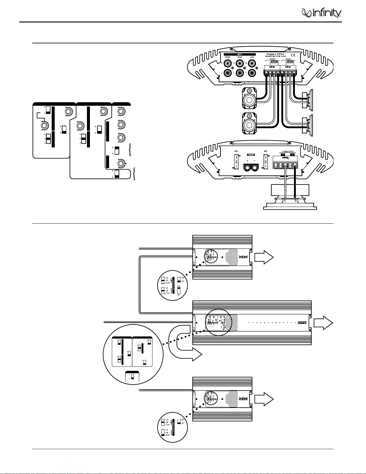
Figure 3. This wiring diagram shows a
Kappa 255a amplifier driving a front
set of tweeter/midrange components, a
rear pair of midbass speakers, and a
single subwoofer.
To Front L/R
Tweeters
To L/R
Midrange
Speakers
To L/R
Midbass
Speakers
To Rear L/R
Speakers
To Subwoofer(s)
Front L/R Inputs
(from Source Unit)
Subwoofer Inputs
(from Source Unit)
Rear L/R Inputs
(from Source Unit)
L/R Outputs
(Low-Pass)
Front L/R Inputs
KAPPA 52a
KAPPA 52a
KAPPA 255a
50w x 4 + 200W x 1
255a
ST
BR
HP
FLAT
LP
.25V
9V
G
A
I
N
G
A
I
N
G
A
I
N
M
O
D
E
M
O
D
E
O
U
T
P
U
T
C
R
O
S
S
O
V
E
R
.25V
9V
.25V
9V
80Hz
20Hz
320Hz
32Hz
60
Hz
Q
FREQ
REAR
INPUT
SUB
INPUT
MIN
MAX
320Hz
32Hz
320Hz
32Hz
HP
FLAT
LP
FRONT LP
EXT
INT
EXT
ST
BR
SUBWOOFER
FRONT REAR
50W X 4
+
200W CLASS D
DIGITAL SUBWOOFER
AMPLIFIER
O
U
T
P
U
T
C
R
O
S
S
O
V
E
R
D
B
O
X
O
V
E
R
x1
x15
SUBWOOFER
REAR
INPUT
FRONT LP
EXT
ST
BR
HP
FLAT
LP
O
U
T
P
U
T
C
R
O
S
S
O
V
E
R
FRONT
x1
x15
ST
BR
HP
FLAT
LP
O
U
T
P
U
T
REAR
SUB
INPUT
INT
EXT
Figure 4. In this expanded
system, a Kappa 52a
drives a front pair of
tweeters. The 52a’s lowpass outputs feed a Kappa
255a to drive stereo pairs
of midrange and midbass
speakers. An external
subwoofer signal feeds the
Kappa 255a to drive the
subwoofer(s). Another
Kappa 52a drives a rear
pair of speakers from the
source unit’s rear outputs.
SYSTEM EXPANSION
5
Kappa 255a
• The Kappa 255a has five levels of circuit protection that
monitor the amplifier and will shut it down if the
electrical system voltage drops below 10 Vdc or exceeds
15.5 Vdc, temperatures are above 194° F (90° C), short
circuits occur, or current draw exceeds product
specifications. For best performance, check the intended
mounting site to make sure the operating environment
does not create conditions that will trigger circuit
protection.
• Prior to installation, turn off all audio systems and other
electrical devices. Also disconnect the (–) negative lead
from the vehicle’s battery.
• At the installation site, locate and make a note of all fuel
lines, hydraulic brake lines, and electrical wiring. Use
extreme caution when cutting or drilling in and around
these areas.
• Use the amplifier as a mounting template to mark
locations for the mounting holes.
• Check clearances on both sides of a planned mounting
surface before drilling any holes or installing any screws.
Remember that mounting screws can extend up to an
inch behind the surface.
• Always wear protective eyewear when using tools.
• The Kappa 255a uses gold-plated, industrial-grade
Weco® plug-in connectors for power and speaker wiring.
Because of precision tolerances, do not insert the
connectors into the amplifier without pre-wiring them
first. Once the wires are fastened in each shell, they
provide additional gripping area for easy connector
removal.
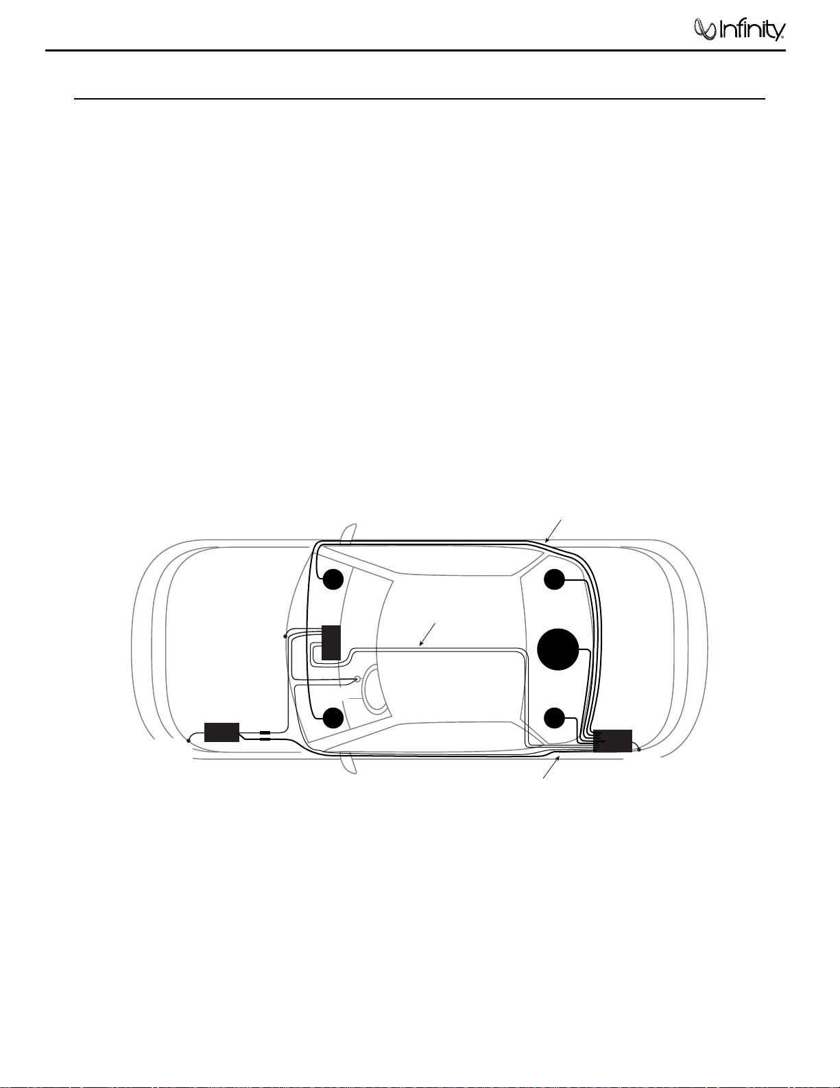
• When routing cables, keep input signal cables away from
power cables and output speaker wires, as shown in
Figure 5 (below).
• When making connections, make sure that each
connection is clean and properly secured. Observe the
polarity markings on the front and rear panels. Refer to
the application drawings (Figures 1 through 3 on pages 4
and 5 ) to set up the amplifier for operation of various
configurations.
• If the amplifier’s fuses need replacement, use only
the same rating and type as replacements. Do not
substitute another kind.
+–
Battery
Fuses
LF
RF
LR
RR
SUB
Kappa 255a
Amplifier
POWER and
REMOTE Cables
Chassis
Ground
Chassis
Ground
Chassis
Ground
Source
Unit
Ignition
SPEAKER Cables
AUDIO Cables
Figure 5. To minimize possible noise pickup, use this suggested cable
routing scheme to plan your amplifier installation.
PRECAUTIONS AND NOTES
6
Kappa 255a
The Kappa 255a is easy to install. For optimum
performance, we recommend using high-quality, twistedpair shielded RCA audio cables and 14-gauge or larger
speaker wire. Also, you’ll need a minimum of 10-gauge
stranded copper wire (e.g., red and black jackets) for the
power connections. Use 18-gauge (e.g., blue jacket) wire for
remote turn-on.
Depending on your total system plan, allow for adequate
time and the possibility of overnight storage of your vehicle,
since it may take more than one day to complete the
installation.
PARTS LIST...
Examine and verify that the package includes the following
items:
• (1) Kappa 255a Power Amplifier
• (2) Spare ATC fast-blow fuses (40 A)
• (1) Control cover with (2) machine screws
• (1) Weco 5-pin audio connector
• (2) Weco 4-pin audio connectors
• (1) Weco 2-pin power connector
• (4) #8 mounting screws
MOUNTING THE AMPLIFIER...
The Kappa 255a can be mounted in virtually any location
inside the vehicle. However, make sure to keep the
amplifier away from heater vents or ducts.
1. At the chosen site, use the amplifier as a mounting
template and mark locations of the four mounting holes.
2. Drill a small pilot hole at each marked location.
3. Mount the amplifier and securely tighten the mounting
screws.
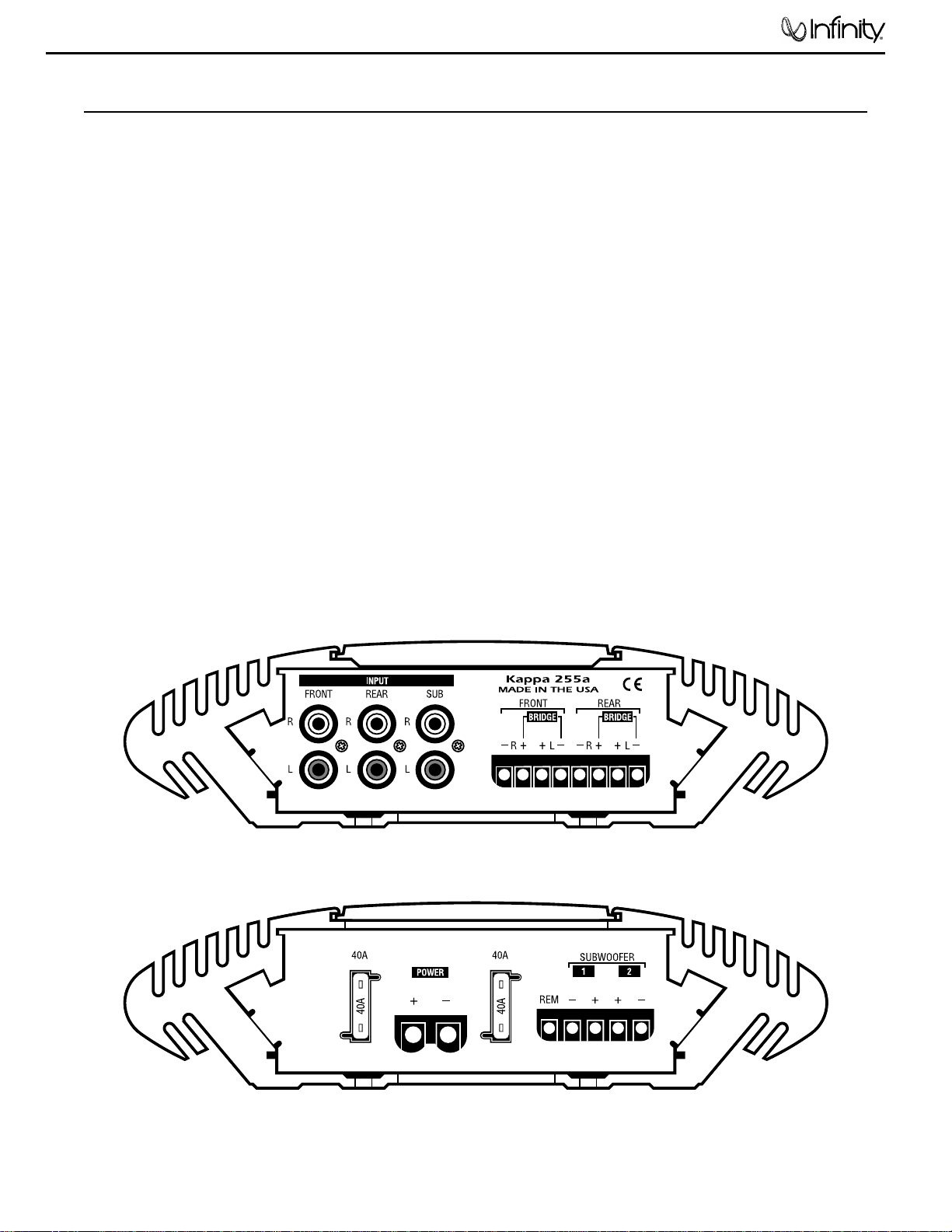
WIRING THE AMPLIFIER...
Refer to Figure 6 (below) for details of the Kappa 255a’s
front and rear panel connections.
1. For power, remote, and speaker wires, strip
1
⁄4" off one
end of each jacket to reveal bare wire for insertion into
the Weco connectors.
2. Using the Weco 2-pin power connector, connect a black
wire from the nearest bare-metal chassis component to
the (–) terminal. Then, connect a red wire from the
vehicle’s +12-volt battery terminal to the (+) terminal.
3. Make sure the wires are firmly seated in the Weco 2-pin
connector and that each screw is completely tightened.
Insert the wired connector into the POWER socket (on the
amplifier’s rear panel). Press it in until it stops.
KAPPA 255a WIRING CONNECTIONS
(front panel)
KAPPA 255a WIRING CONNECTIONS
(rear panel)
R L
Figure 6. W iring connections for the Kappa 255a amplifier.
INSTALLATION
7
Kappa 255a
4. Using the Weco 5-pin connector , connect a blue wire from
the source unit’s remote connection to the REM terminal.
Depending on polarity requirements (see Figures 1
through 3 on pages 4 and 5), connect speaker wires from
the subwoofer(s) to the L and R (+ and –) terminals, as
required by your system plan.
5. Make sure the wires are firmly seated in the Weco 5-pin
connector and that each screw is completely tightened.
Insert the wired Weco 5-pin connector into the
SUBWOOFER socket (on the amplifier’s rear panel).
Press it in until it stops.
6. Using Weco 4-pin connectors, connect speaker wires from
the front and rear speakers to the amplifier. Depending
on your system plan (see Figures 1 through 3 on pages 4
and 5 ), match the polarities on the L and R (+ and –)
terminals.
NOTE: In 3-way applications, the rear amplifier provides
bandpass channels to drive midrange or midbass speakers.
7. Make sure the wires are firmly seated in each Weco 4pin connector and that each screw is completely tightened.
Insert the wired Weco 4-pin connectors into the FRONT
and REAR sockets (on the amplifier’s front panel). Press
each one in until it stops.
8. Connect RCA cables from a source unit to the L /R,
FRONT/REAR INPUT jacks. If the source unit has
subwoofer outputs, also connect a pair of RCA cables from
those jacks to the SUB INPUT jacks and set the SUB
INPUT switch to EXT (see Figure 7).
SETTING THE CROSSOVERS...
1. To use the Kappa 255a in a front/rear system, set the
CROSSOVER controls to frequencies recommended by
the speaker manufacturer (see Figure 7). If the value is
unknown, set the control midway.
2. For a 3-way system, set the OUTPUT and REAR INPUT
switches to create the appropriate bandpass filters (see
Figures 2 and 3 on pages 4 and 5).
SETTING INPUT SENSITIVITY...
Initially, turn the front and rear input sensitivity GAIN
controls to their minimum (counter-clockwise) positions
(refer to Figure 7).
1. Reconnect the (–) negative lead to your vehicle’s battery.
Apply power to the audio system and play a favorite
music track from CD or tape.
NOTE: After the source unit is on, green LEDs (on the top
panel) will illuminate, indicating the amplifier is on. If not,
check the wiring, especially the remote connection from the
source unit. Also refer to “Troubleshooting” on the next page.
2. On the source unit, increase the volume control to
maximum position. Slowly increase the Front and Rear
GAIN controls (clockwise) towards three o’ clock and, at
the same time, listen to the quality of the reproduced
sound. At some point, you’ll hear distortion on the music
peaks. Stop the adjustment and turn it back slightly.
SETTING DBO...
Dynamic Bass Optimizer (DBO) is a new approach to
enhancing low-frequency reproduction in a vehicle.
Conventional bass boost controls add bass at a fixed
frequency and cause the amplifier to consume considerable
power. DBO conserves valuable power at the lowest
frequencies and allows you to adjust the level and
“character” of the bass sound, instead of just the amount of
boom.
Since a subwoofer in a tuned box is given to overexcursion
below the tuned frequency, set the FREQ control below the
box’s resonant (tuned) frequency (see Figure 8 on
page 2).
Power typically wasted in this region will now be
conserved and instead be available for frequencies the
enclosure will reproduce. Use the Q control to boost the
bass at the set frequency by as much as 12 dB (at MAX
position –
see Figure 8 on Page 2).
For sealed enclosures, use DBO to enhance the output so it
sounds more like a tuned box. This is a result of 12 dB of
rolloff being added to the enclosure’s rolloff and a flattening
of frequency response (at the curve’s knee) when Q is
boosted.
For infinite baffles, set the FREQ control to the speaker ’s
F
s
value (to keep the subwoofer from trying to create bass
below the resonant frequency) and adjust the Q control
according to personal taste.
INSTALLING THE CONTROL COVER...
After wiring and testing the Kappa 255a amplifier, install
the control cover using the enclosed machine screws to
deter tampering and help seal out dust.
NOTE: Do not over-tighten the machine screws. Doing so may
crack the cover.
ST
BR
HP
FLAT
LP
.25V
9V
G
A
I
N
G
A
I
N
G
A
I
N
M
O
D
E
M
O
D
E
O
U
T
P
U
T
C
R
O
S
S
O
V
E
R
.25V
9V
.25V
9V
80Hz
20Hz
320Hz
32Hz
60
Hz
Q
FREQ
REAR
INPUT
SUB
INPUT
MIN
MAX
320Hz
32Hz
320Hz
32Hz
HP
FLAT
LP
FRONT LP
EXT
INT
EXT
ST
BR
SUBWOOFER
FRONT REAR
50W X 4
+
200W CLASS D
DIGITAL SUBWOOFER
AMPLIFIER
O
U
T
P
U
T
C
R
O
S
S
O
V
E
R
D
B
O
X
O
V
E
R
x1
x15
INSTALLATION (continued)
Figure 7. Kappa 255a controls for crossover, input, output, and
DBO (Dynamic Bass Optimizer).
8
Kappa 255a

Use the following guide to identify symptoms and solve
problems. Make sure the vehicle’s electrical system is
working properly and power is reaching the Kappa 255a
(i.e., green LEDs on the top panel are on).
SYMPTOM LIKELY CAUSE SOLUTION
No audio Low/No Remote Check connections;
Turn-On Voltage test turn-on voltage
Speakers are not Check wiring; use
connected or are VOM/DVM to
blown measure speaker
coil impedance
Distorted audio Input sensitivity See
Setting Input
is not set properly Sensitivity on
previous page
Audio lacks Speakers are wired Check polarity of
“punch” with wrong polarity connections; refer to
Applications
SYMPTOM LIKELY CAUSE SOLUTION
Audio cycles A protection circuit Verify the following–
off and on; is turning the electrical system is
Amber protec- amplifier off and on between
10 ~ 15.5
Vdc;
tion LEDs (on temperature is not
top panel) are on over 194°F (90°C);
no short circuits;
speaker loads are not
less than 1 ohm
(2 ohms in mono)
Audio cycles GAIN is set too high Set Input Sensitivity
off and on; correctly (see previous
Amber protection page)
LEDs (on top
panel) are on
Fuse blows Incorrect wiring or Check connections;
short circuit refer to Applications
TROUBLESHOOTING
9
Kappa 255a
10
Kappa 255a
Service Bulletin
Service bulletin INF9701 Rev1 - August 2001 This is considered a Major repair
To: All Infinity Service Centers
Models: Kappa 255a
Subject: Damaged Output Transistors
When the voltage from an automotive battery powering the Kappa 255a dips repeatedly dips below 8 volts, the
class D regulator can become unstable. As result, excessive current flow can damage output transistors
Q10,11,12,13 in the subwoofer section.
In the event you receive a Kappa 255a for any servicing reason, perform the modification as shown
below. Affected units will have an “HC” in the prefix in a white serial # label (bottom of the unit).
Note: Many components in this product, including two due for replacement, are Surface Mount Devices.
Procedure:
1) Remove the (24) 9/64” allen screws from both lower sides of the chassis.
2) Remove the (2) #10 Torx screws from the bottom chassis underneath the tamper-proof labels.
3) Turn amplifier vertically and strike on a hard surface, dislodging the main PCB; slide entire assembly out of
the chassis.
4) Remove and replace any defective
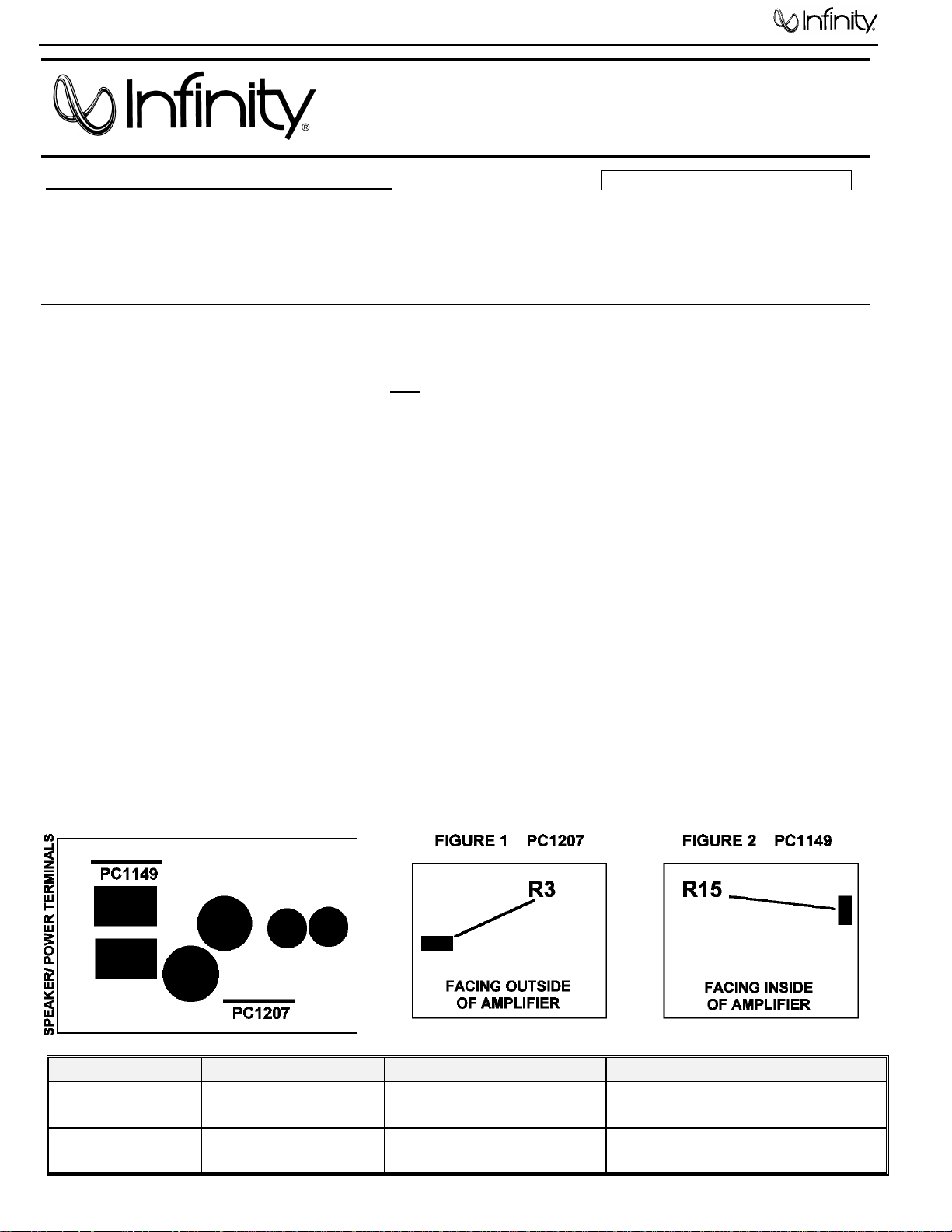
5) Change R3 on the Digital Predriver Module (PC1207) from 22kW to 2.2kW (Infinity part# RS1703). PC1207
is the small upright board located near the main PCB filter capacitors. R3 is on the component side of the
board facing the outside of the amplifier. See Figure 1.
6) Change R15 on PWM Module (PC1149) from 1kW to 2.2kW W (Infinity part# RS1703). PC1149 is the small
upright board located near the main power supply transformers. R15 is on the component side of the board
facing the inside of the amplifier. See Figure 2.
7) Reinsert main PCB into chassis; confirm that all (20) insulators are still in place, attached with heat sink
compound to each output device.
8) Insert and tighten all (24) chassis screws, including the (2) Torx screws on the bottom of the unit. Note: the
(4) shorter, 5/8” screws are inserted at the ends of the amp chassis.
9) Attach all power, speaker and signal cables to amplifier and test.
IRFS250 output transistors. (Q10-13 are Infinity part# TR1238)
Model Serial number Status Acti on
KAPPA 255a “HC” in the prefix
below -01701
KAPPA 255a “HC” in the prefix
-01701and above
Damaged Q10,11,12 or 13 Change R3 & R15
to 2.2kW
Modified by factory NONE REQUIRED

11
Kappa 255a
Service Bulletin
Service Bulletin INF2001-02 - September 2001 Warranty labor rate: MAJOR repair
To: All Infinity Service Centers
Model: Kappa 255a
Subject: No Sound from Subwoofer Output
In the event you receive a Kappa 255a with the complaint: “No sound from the subwoofer output”,
replace transistor Q18 SMD (Surface Mount Device) with a TO-220 package, TIP31C transistor. For
details, see instructions as described below. All KAPPA 255A amplifiers with serial numbers starting
with letters “CL” should be modified. The serial number is printed on a white label, located on the
bottom of the Kappa 255A enclosure.
Note: Many components in this product, including the one due for replacement, are Surface Mount Devices.
Procedure:
1) Remove the (24) 9/64” Allen screws from both lower sides of the chassis.
2) Remove the (2) #10 Torx screws from the bottom chassis underneath the tamper-proof labels.
3) Turn amplifier vertically and strike on a hard surface, dislodging the main PCB; slide entire assembly out
of the heatsink.
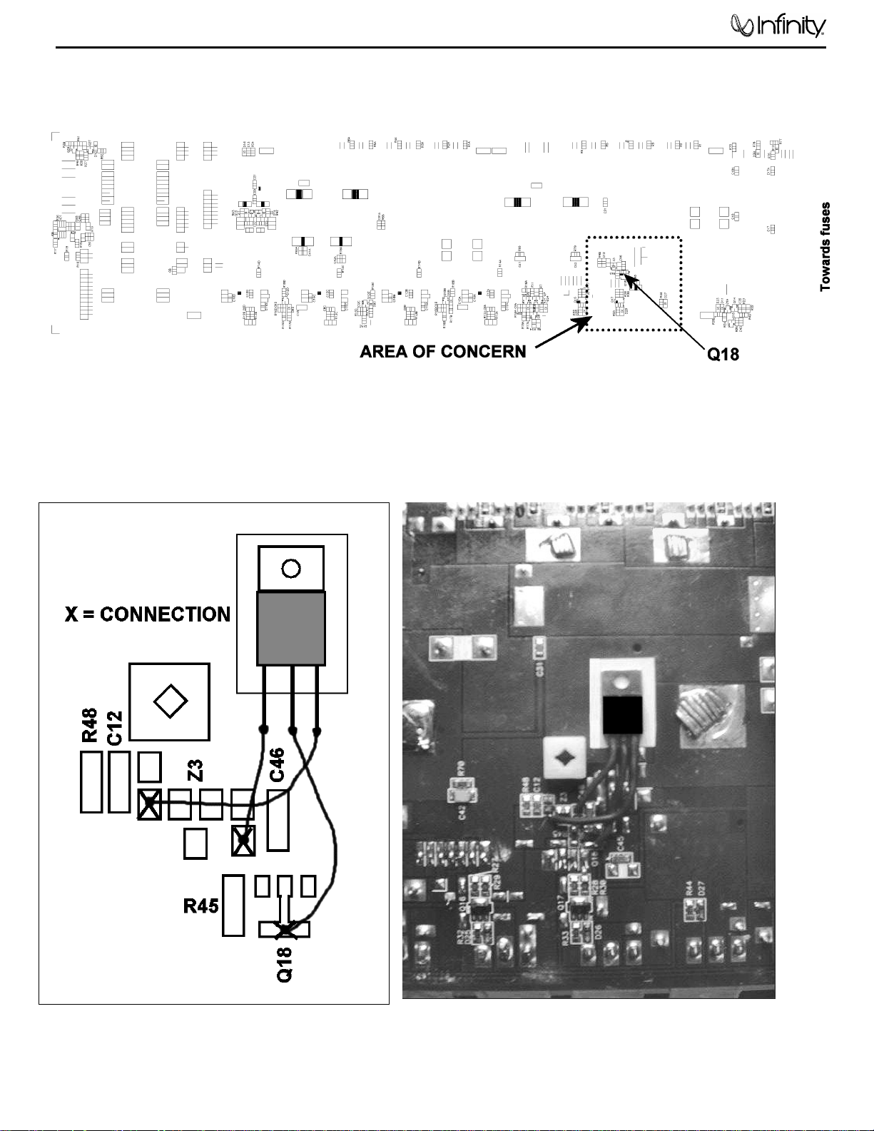
4) Locate, identify, and remove Q18 SMD transistor on the bottom of the main PCB. See illustrations on
page 2.
5) Prepare the nearby area on the PCB by applying a white .5" x .75" BONDPLY insulator, (Infinity part#
TO-220 BONDPLY-100) in the area where a new TIP31C transistor will be mounted.
6) Apply a transistor TIP31C (Infinity part# TR1183) on top of the insulator; press firmly to set. Transistor
should be flat on the PCB.
7) Extend the three leads of the transistor by soldering a length of 22 gauge buss wire to each lead, the
length determined by the connection points. Solder each wire piece to each lead (longer is better as it
can always be cut) and then trim to the correct length. You will NOT be re-connecting the three leads to
the tiny solder pads for the original SMD device; study the illustrations to locate the three final connection
points.
8) Cut three pieces of 1/16” vinyl or shrink tubing to insulate the three exposed leads, leaving enough wire
exposed at the end to make the final soldered connections.
9) Solder the three leads in the areas shown in the illustration. Transistor Q18 and new connecting wires
MUST NOT be higher than the square plastic standoff next to it.
10) Add a dab of RTV (silicon seal or similar non-conductive compound) to the area of the three leads.
11) Test the unit, still out of the heatsink, by applying power, with signal and subwoofer connections WITH
NO LOUDSPEAKER LOAD other than a DMM or an oscilloscope on the output terminals.
12) Reinsert main PCB into chassis; confirm that all (20) insulators on the output devices are still in place,
attached with heat sink compound on each one.
13) Insert and tighten all (24) chassis screws, including the (2) Torx screws on the bottom of the unit. Note:
the (4) shorter, 5/8” screws are inserted at the ends of the amp chassis.
14) Attach all power, speaker and signal cables to amplifier and test with loudspeaker load.
MODEL SERIAL NUMBER
KAPPA 255a
“CL” in the serial # prefix
All units affected
STATUS
Q18 Overheating
ACTION
Replace Q18 with
TIP31C transistor
12
Kappa 255a
13
Kappa 255a
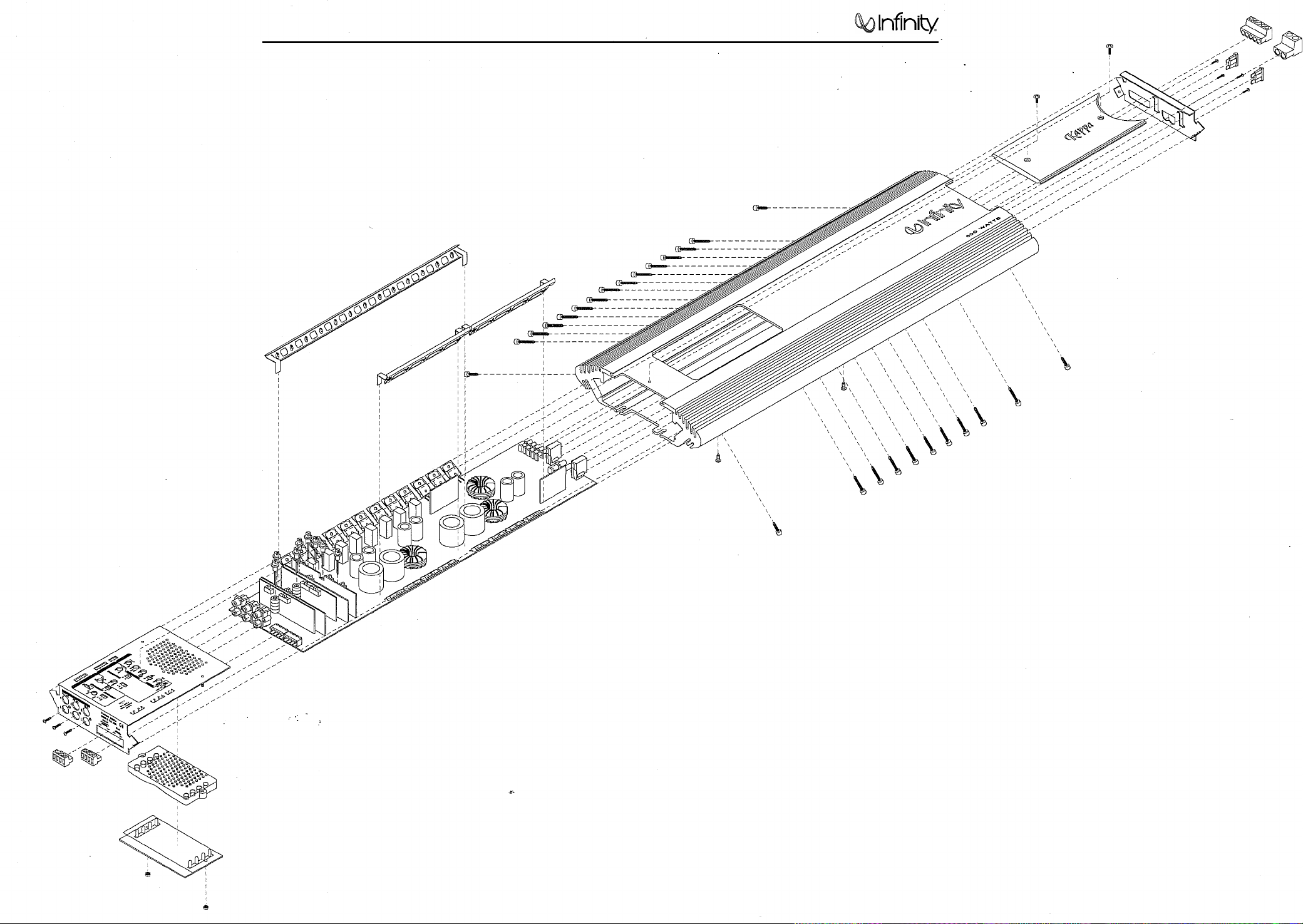
Kappa 255a Exploded View
 Loading...