


Infinity TSSSUB-1200 Service manual
TSS-Sub1200
(TSS-1200 SYSTEM)
SERVICE MANUAL
Infinity Systems Incorporated
250 Crossways Park Dr.
Woodbury, New York 11797 Rev0 12/2006

1
TSS-Sub1200 subwoofer
Note: The TSS-Sub1200 is part of the TSS-1200 system
Satellite loudspeakers:
(Charcoal) order Infinity p a rt# TSS-SAT1200CHR
(Platinum) order Infinity part# TSS-SAT1200PLT
Center channel:
(Charcoal) order Infinity part# TSS1200CHR CEN
(Platinum) order Infinity part# TSS1200PLT CEN
CONTENTS
BASIC SPECIFICATIONS . . . . . . . . . ………………….………….... .. . . . . . 1
DETAILED SPECIFIC ATIONS . . . . . . . . . . . . . . . . . .………. . .. .. .. . . . . . 2
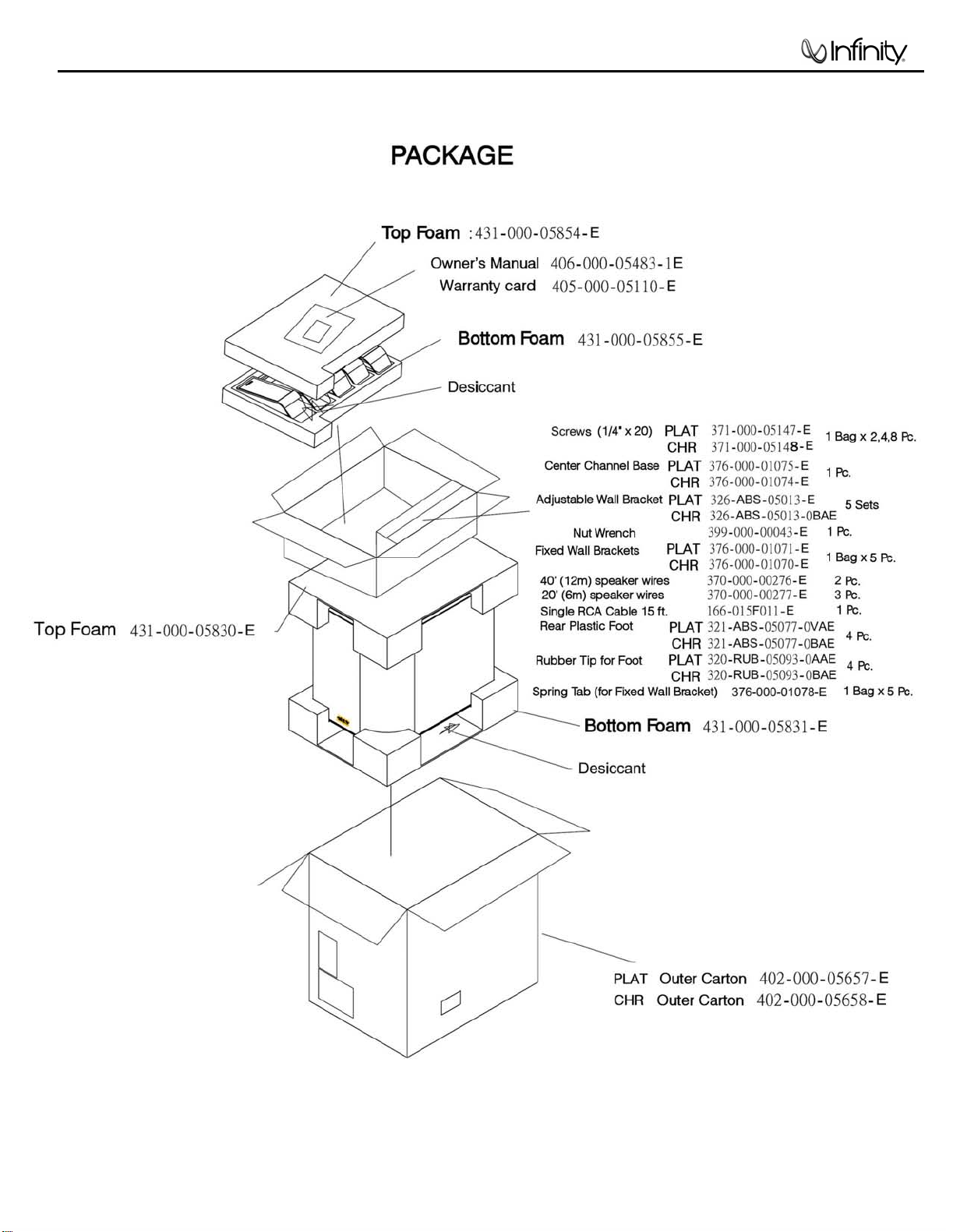
PACKAGING/ACCESSORIES. . . . . . . . . . . . . . . . . .………. . .. .. ... . . . . . 4
CONTROLS. ………………….. .. . …………………………………………….. 5
CONNECTIONS . . . . . . . . . . . ……….………………………………..…. . . . 6
OPERATION……. . . . . .. . . . . . . . .. .. . . . .. .. . . . . ….……… . . ... . . . . . . .7
EXPLODED VIEW-MECHANICAL PARTS LIST….… . ………………………..8
TEST SET-UP/PROCEDURE. . . . . . . . . . . . . . . . . .………. . .. .. .…. . . . . . 9
BLOCK DIAGRAM. . . . ………………... ………………………….... . . .. . … . 10
PCB DRAWINGS. .. . . . . . . . . . . . . . .. . . . . ……………………………….. …11
ELE CTRI CAL PAR T S LIST …………. ………………………………………….13
IC – TRANSISTOR PINOUTS . … . . .. . . . . . ………………………….... . . . 16
SCHEMATIC DIAGRAMS . . …………………………………….……………. . .17
TSS-Sub1200 Specifications
Frequency Range: 29Hz – 150Hz (±3dB)
Amplifier Output: 250 Watts RMS; 500 Watts peak
Low-Frequency Driver: 12" (305mm)
Crossover Frequency: 50Hz – 150Hz, 24dB/Octave, continuously variable
Dimensions (H x W x D): 18-1/2" x 12-3/4" x 18-1/2"
(470mm x 324mm x 4 70mm)
Weight: 44 lb (20kg)
Infinit y cont inually str i ves to update and improve existing products, as well as create new ones. The specificati ons and
construction detail s i n this and related Infinity publications are therefore subject to change without notice.
A
2
TSS-Sub1200 subwoofer
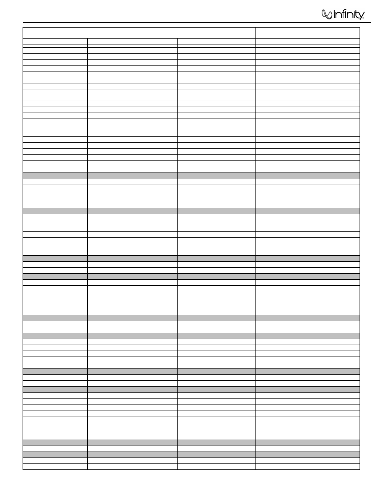
INFINITY TSS-1200 250W Powered Sub/ Plate Amp
LINE VOLTAGE Yes/No Hi/Lo Line Nom. Unit Notes
Parameter Specification Unit
Amp Section
Type (Class AB, D, other) D n/a
Load Impedance (speaker) 5.6 Ohms
Rated Output Power (120VAC 150 Watts
Rated Output Power (230VAC 150 Watts
AVG RMS Dynamic Power 250 Watts
AVG RMS Dynamic Power 250 Watts
THD @ Rated Power 0.5 %
THD @ 1 Watt 0.1 %
DC Offset 10 mV-DC
Damping factor >50 DF
Input Sensitivity
Input Frequency 35 Hz
L or R input 16.8 mVrms
L or R input 16.8 mVrms
Gain L & R 140
Signal to Noise
SNR-A-Weighted 90 dBA
SNR-unweighted 85 dBr
SNR rel. 1W-unweighted 65 dBr
Residual Noise Floor 1 mVrms(max)
US 120vac/60Hz Yes 108-132 120 Vrms Normal Operation
EU 230vac/50-60Hz Yes 207-264 230 Vrms Normal operation, MOMS required
QA Test
Limits Conditions Notes
n/a
n/a
Nominal
125 Domestic version only 120 VAC-60 Hz
125 EU Version only 230 VAC-50 Hz
verage RMS power, 3/20 Cycles 50 Hz, Driven
225
5.6 Ohms
189
4 Ohms
1
22K filter
0.3
22K filter
30
Amplifier output
20
Measured at amplifier board
35
Nominal Freq.
±2dB
To 1 Watt, Ap Zo=600 Ohms Single input driven, Normal mode
±2dB
To 1 Watt , Ap Zo=600 Ohms Single input driven, LFE mode switch ON
±2dB
43 dB
85
relative to rated power A-Weighting filter
85
relative to rated power 22K filter
65
relative to 1W Output 22K filter
Volume @max, w/ A/P Swept
Bandpass Measurement (Line
1.5
freq.+ harmonics) (BW=20 Khz)
6dB above its input sensitivity sensitivity
Reference
Measured at the amplifier board. 120 Watts @
50 Hz, THD must be less tan 0.1%
Reference
Line level inputs must be terminated using
1KOHM
Input Impedance
Line Input (L, R) > 10K ohms
Filters
LP filter 4th order 50-150 Hz
HP Filter 2nd order Fixed
LFE Low pass 2nd order 200>LP<1K Hz
Notch filter (Friend circuit)
Limiter
THD at Max. Output Power
Features -Volume pot Taper (lin/log)
Phase switch
LP Filter defeat switch (LFENormal)
Input Configuration
Line In (L,R) & LFE
Signal Sensing (ATO)
Auto-Turn-On (yes/no) YES
ATO Input test frequency 50 Hz
ATO Level LFE Input 2 mV
ATO Turn-on time 5 ms
Auto Mute/ Turn-OFF Time 15 minutes
n/a n/a functional
LOG --
0-180 deg
YES
YES --
n/a
Nominal
± 10
2nd Order variable and 2nd order fix
LFE input driven only
F=61 Hz, Q=3.607, Av=-8.62dB
Maximum Output Power Maximum THD as a result of limiting.
functional
functional
functional Disables LP filter, intended for LFE
functional Dual RCA jack
functional
functional
functional
functional
18
Amp connected and AC on, then
input signal applied
T before muting, after line or
speaker level signal is removed
"
" Maximum acceptable level.
See AP curves 2nd order variable + 2nd order
fix-24 db/Octave
A Taper
Auto turn of time (T) must be 5 > T < 18
Minutes
Power on Delay time 3 sec.
Transients/Pops
ATO Transient 5 mV-peak
4
AC Power Applied
n/a
@ Speaker Output
3
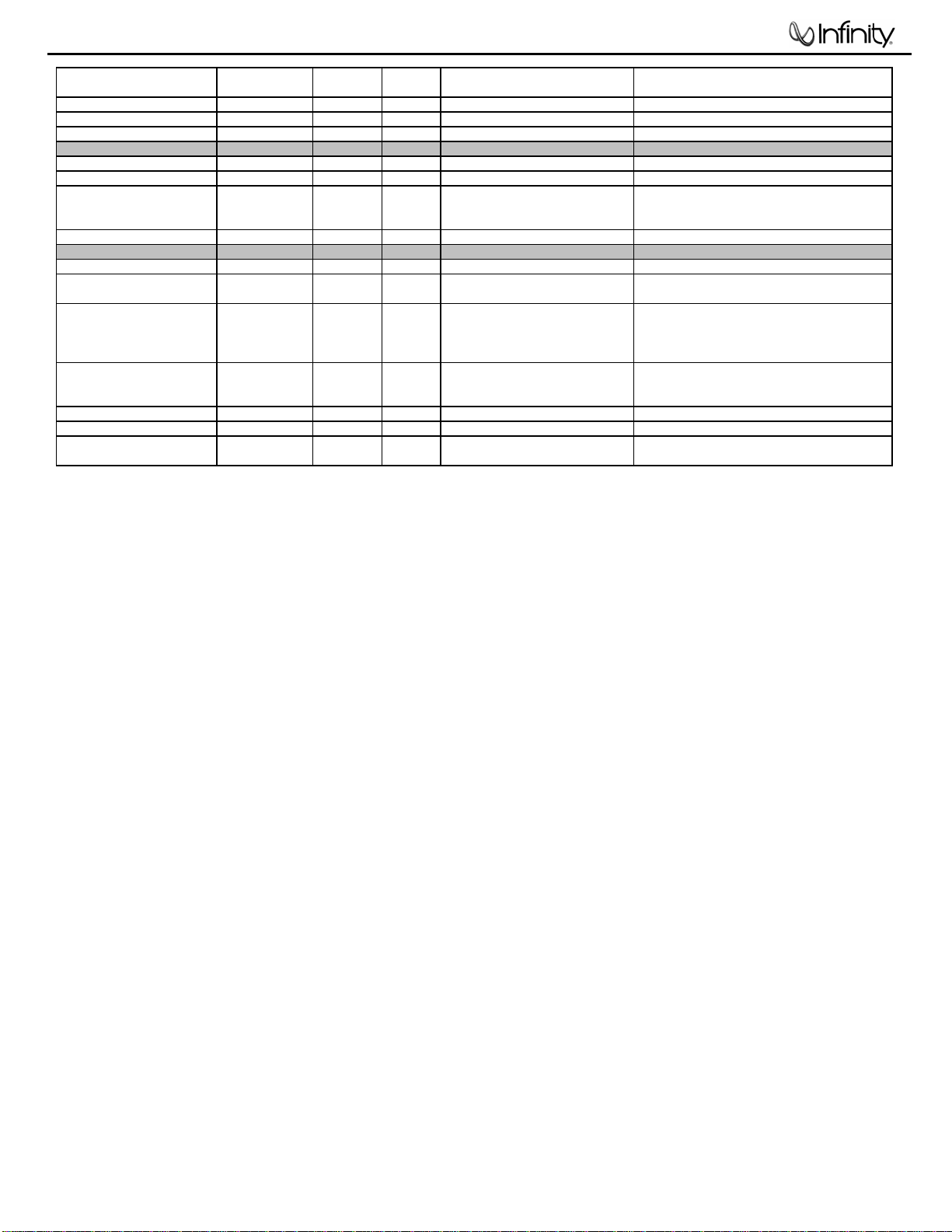
TSS-Sub1200 subwoofer
Parameter Specification Unit
QA Test
Limits Conditions Notes
Turn-on Transient 50 mV-peak
Turn-off Transient 50 mV-peak
Efficiency
Efficiency 67 %
Stand-by Input Power 20 Watts
Power Cons. @ rated power 185 Watts
Protections
Short Circuit Protection YES
Thermal Protection YES
DC Offset Protection YES
Line Fuse Rating
USA-Domestic 2 Amps
EU 1.25 Amps
2V-pk-pk
2V-pk-pk
65
22
187
functional
functional
-
2
1.25
@ Speaker Output AC Line cycled from OFF to ON
@ Speaker Output AC Line cycled from ON to OFF
Nominal Line voltage 120 VAC
Maximum allowable input power under nominal
Input voltage and frequency, HOT or COLD
@ nom. line voltage
@ nom. line voltage 125 Watts into 5.6 Ohms @ nominal line voltage
Direct short at output
@1/8 max unclipped Power at 1.06
times the input voltage
DC present at Speaker Out leads
Type-T or Slo Blo-250 V Internal fuse with UL/SEMKO rated holder
Type-T or Slo Blo-250 V, Low
Breaking capacity
operation.
Amplifier should resume operation after short
circuit condition removal
Temperature rise in accessible metal parts
should not exceed 35K rise for domestic version
or 30K rise for European versions (refer to
requirements sheet).
Design must insure no Offset at the speaker
output under any operating condition including
abnormal operation
Internal fuse with UL/SEMKO rated holder
4
TSS-Sub1200 subwoofer
CROSSOVER
FREQUENCY
LEVEL
LINE LEVEL IN
PHASE
Min
Max
L R
For LFE use L or R
LFE NORMAL
POWER
50Hz
80Hz
0˚ 180˚
150Hz
CAUTION
RISK OF ELECTRIC SHOCK
DO NOT OPEN
ON OFF
NRTL/C
CSA22.2
UL1492
®
®
WARNING: TO REDUCE THE RISK OF FIRE OR ELECTRIC SHOCK,
DO NOT EXPOSE THIS APPLIANCE TO RAIN OR MOISTURE.
AVERTISSEMENT: POUR PRÉVENIR LES RISQUES D’INCENDIE OU
DE CHOC ÉLECTRIQUE, ÉVITER D’EXPOSER CET APPAREIL A LA
PLUIE OU A L’HUMIDITÉ.
5
TSS-Sub1200 subwoofer
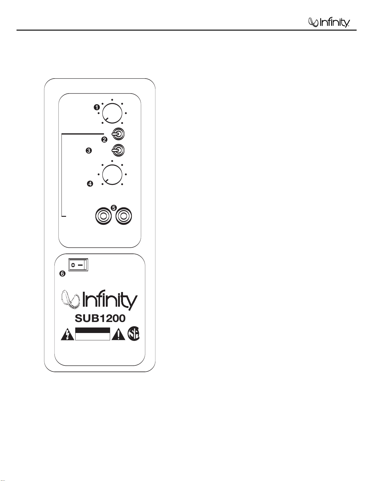
SUBWOOFER CONTROLS
1
Rear Panel
Subwoofer-Level Control
2
LFE/Normal Switch
3
Phase Switch
4
Crossover-Frequency Control
5
Line-Level (LFE) Inputs
6
Power Switch
A Few Suggestions
We recommend that you do not operate your speakers or
subwoofer with the bass,treble and loudness controls set to
full boost.This will place undue strain on your electronics and
speakers and could damage them.
The volume control setting on your processor/preamp or receiver
is not a specific indication of the overall loudness level of the
speakers.The only important consideration is the loudness level at
which the system can be played, regardless of where the volume
control is set.
Always turn down the volume control setting on your processor/
preamp or receiver when changing a cassette or CD, or switching
inputs to AM or FM operation. Excessively loud transients (clicks or
popping sounds) can damage the satellite speakers and possibly
the subwoofer.
Important!
Whenever changing cables, pulling plugs, etc.,ALWAYS TURN OFF
ALL EQUIPMENT, including the subwoofer.
 Loading...