


Infinity IL-120-S Service manual
Interlude Series
IL120s Subwoofer
Service Manual
Infinity Systems, Inc
250 Crossways Park Dr.
Woodbury, New York 11797
REV 1 10/2001

IL120s
CONTENTS
SPECIFICATIONS …….…………………………….………………….3
DETAILED SPECIFICATIONS ……………………..…………………4
CONTROLS and CONNECTIONS ………………….….….…………6
OPERATION……………………………………..……..…..…….……..8
BASS OPTIMIZATION SYSTEM…………….………….….…………9
MECHANICAL/PACKING PARTS LIST………………..……………11
EXPLODED VIEW ……………………………………….……………12
PACKAGING …………………………….………………………….…13
EXPLODED VIEW OF AMPLIFIER…………………….……………14
TEST SETUP and PROCEDURE……………….……..……………15
IL120s ADJUST BIAS PROCEDURE………………..…………………16
PRINTED CIRCUIT BOARD DIAGRAMS………………..…………17
ELECTRICAL PARTS LIST (120v)…………………….….…………23
INTEGRATED CIRCUIT DIAGRAMS ………………………………31
IL120s SCHEMATICS…………..……….……………………………32

IL120s
3
SPECIFICATIONS
IL120s Frequency Response: 28Hz - 150Hz (±3dB)
Maximum Amplifier Output: 500 watts (20Hz - 150Hz with no more than 0.1% THD)
Crossover Frequencies: 50Hz - 150Hz, 24dB/octave, continuously variable
Driver: 12" C.M.M.D.
Dimensions (H x W x D): 17-1/2" x 17-1/4" x 19-3/4"
Weight: 45 lb (20.5kg)
Optional Accessory: Bass Optimization
Test & Measurement Kit:
Part Number: 335852-002

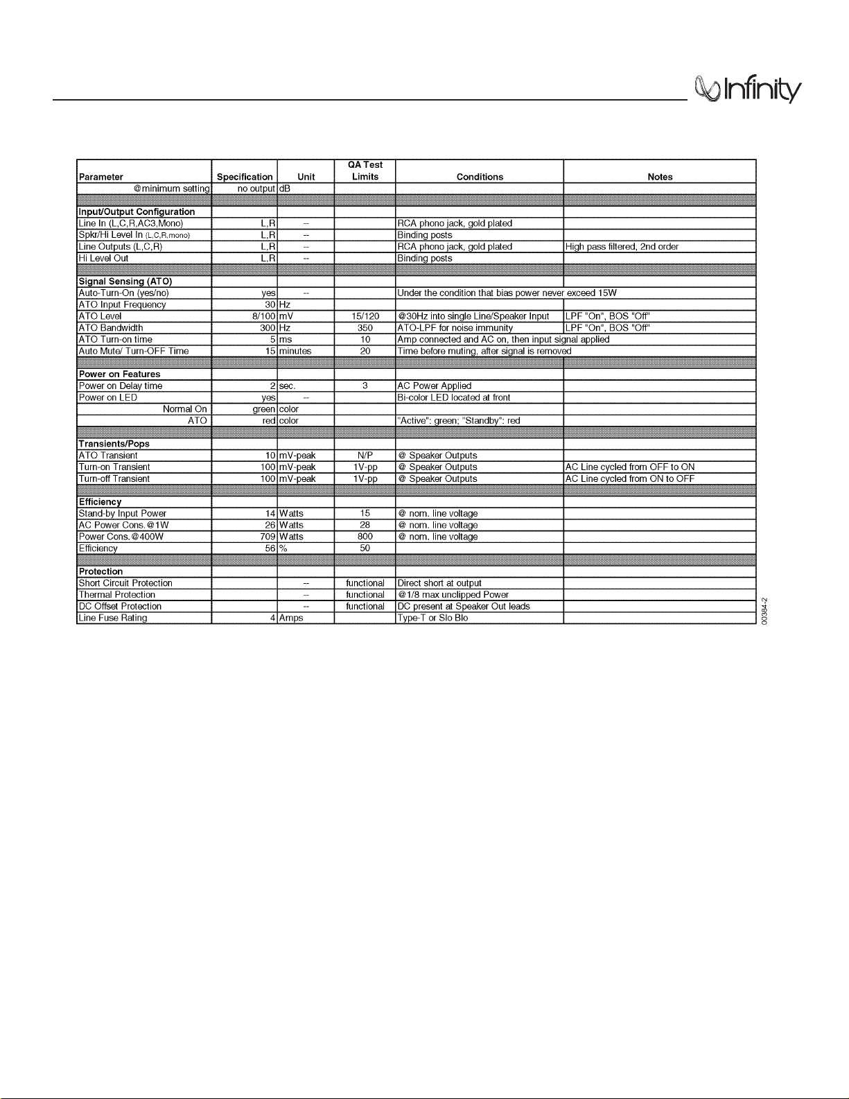
DETAILED SPECIFICATIONS
IL120s
4
IL120s
5
DETAILED SPECIFICATIONS (Cont.)
IL120s
6
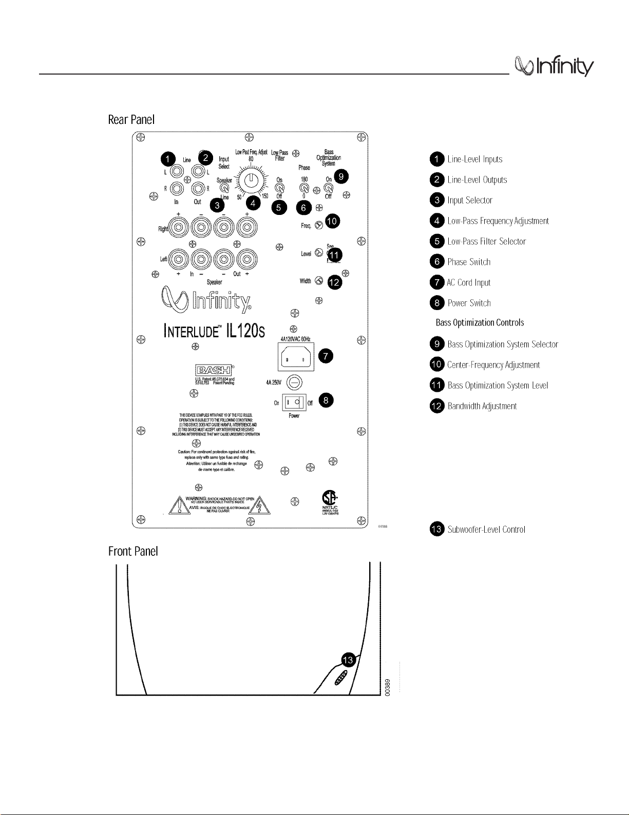
CONTROL and CONNECTIONS
IL120s
7
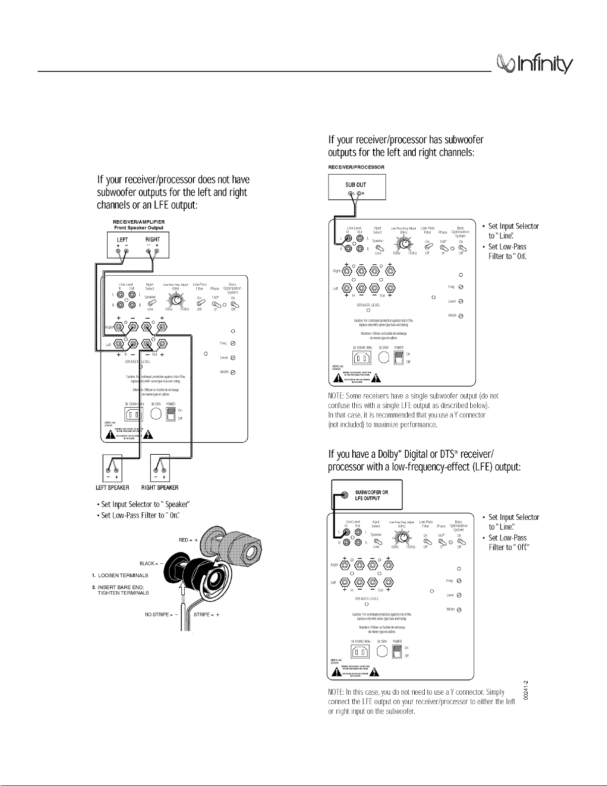
CONNECTIONS
IL120s
8
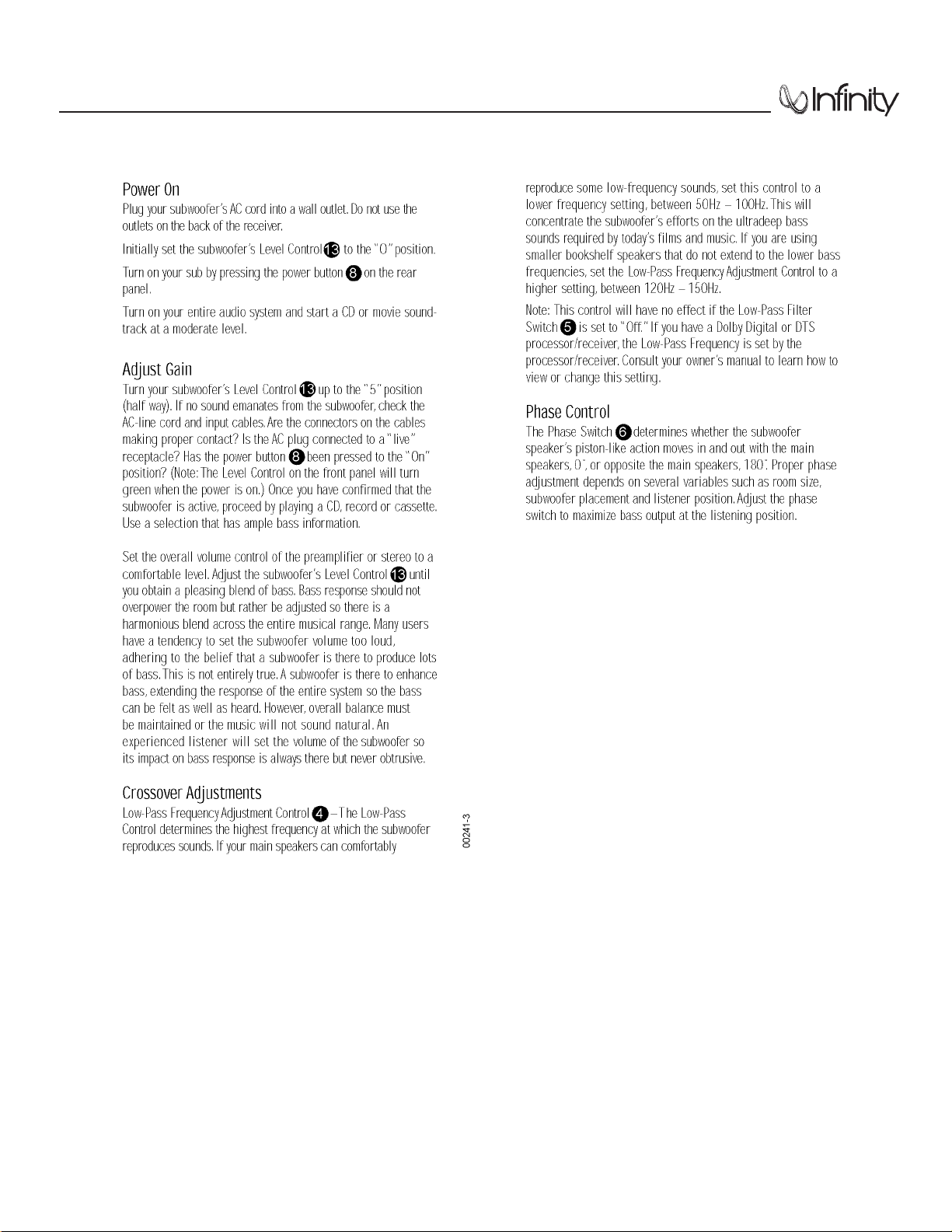
OPERATION
IL120s
9
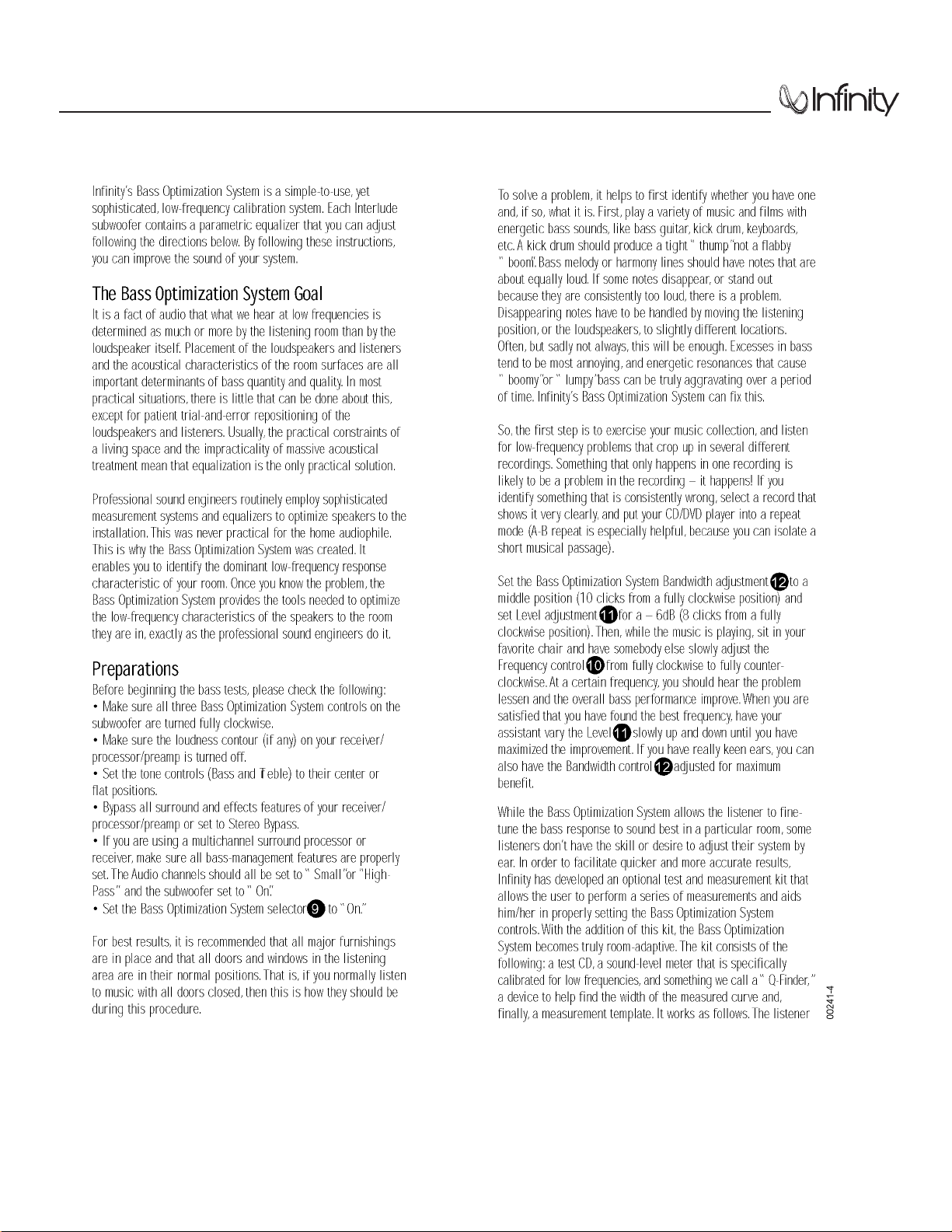
BASS OPTIMIZATION SYSTEM
TM

IL120s
10
BASS OPTIMIZATION SYSTEMTM(Cont.)
plays the tones from the test CD and records the relative output level of each test tone, using the sound-level meter,
on the provided measurement template. After all the tones are complete, the template contains a response curve
for the frequencies below 100Hz. The user simply notes the frequency of the largest bass peak, calculates the correct amount of attenuation, and uses the “Q-Finder” to determine the width of the curve. These three values are
dialed into the Bass Optimization System controls located on the speaker. The entire process takes less than twenty minutes.
If your dealer does not stock the Bass Optimization System test and measurement kit, you may purchase it directly
from Infinity. U.S. residents can visit our Web site at www.infinitysystems.com or call 1-800-553-3332. Canadian
residents should contact their dealer or call 1-800-567-3275.
Ask for Infinity part number 335852-002.

IL120s
11
MECHANICAL/PACKAGING PARTS LIST
MECHANICAL
IL120s COMPLETE AMPLIFIER ASSY N/A
WOOFER, 12”, C.M.M.D., shielded, 3.4 ohms ±10% 336056-001
VOLUME CONTROL, R-IL 336250-001
FRONT BAFFLE 336439-001
PORT TUBE 336799-001
GRILLE CUP (12) 333249-003
GRILLE, GRAY 336441-001
GRILLE, MIDNIGHT BLUE 336441-002
GRILLE, RICH BURGUNDY 336441-003
GRILLE, BLACK 336441-004
PACKAGING
OWNER’S MANUAL, IL100S/IL120S 335839-001
WARRANTY CARD 335841-001
SURVEY CARD 330033-001
CARTON 336497-001
FOOT (4) 334186-002
FOOT PAD (4) 334192-001
PAD, END, TOP 336496-001
PAD, END, BOTTOM 336496-002
GRILLE ASSEMBL Y See Options Above
POWER CORD, 120V US-15’ 336658-115
RABOS SCREW DRIVER 335848-002
Description Part Number
IL120s
12
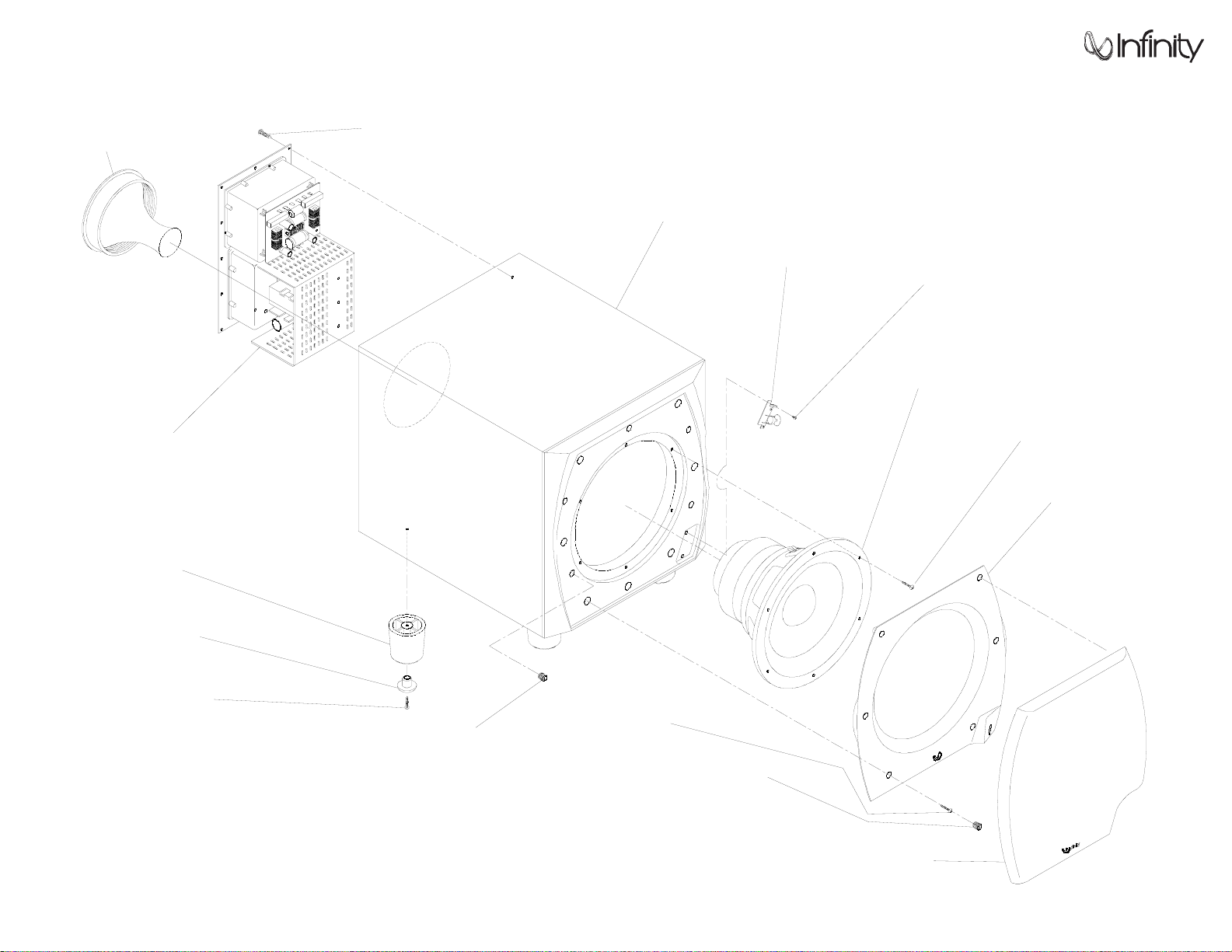
EXPLODED VIEW
CABINET
(NOT FOR SALE)
WOOFER, 12"
(336056-001)
VOLUME CONTROL, R-IL
(336250-001)
FRONT BAFFLE
(336439-001)
PORT TUBE
(336799-001)
GRILLE CUP (6)
(333249-003)
GRILLE CUP (6)
(333249-003)
GRILLE, GRAY 336441-001
GRILLE, MIDNIGHT BLUE 336441-002
GRILLE, RICH BURGUNDY 336441-003
GRILLE, BLACK 336441-004
FOOT (4)
(334186-002)
FOOT PAD (4)
(334192-001)
OO514
IL120s
AMPLIFIER ASSY
(NOT FOR SALE)
TO SERVICE THE IL120s SUBWOOFER
1) Remove the grille.
2) Extract (6) rubber grille retainers as shown in the illustration above, this can be accomplished by
carefully pulling them out of the cavities with long-nosed pliers or similar tool.
3) Remove the ( 6) Phillips screws that are now exposed.
4) Remove the front baffle.
5) Remove the (6) screws that secure the driver.
6) To service the amplifier, remove the (12) Phillips screws at the rear of the enclosure, and pull the
amplifier out of the back.
SCREW, (2)
#6 x .75, PB, PPH, BLK
(903401-012)
SCREW, (6)
#6 x .75, PB, PPH, BLK
(903401-012)
SCREW, (12)
#8 x .75, PB, PPH BLK
(900101-012)
SCREW, (6)
#8 x .75, PB, PPH BLK
(900101-012)
SCREW,
#8 x 1, PB TRPH BLK
(903101-016)
 Loading...