

Page 1
RS-3000
Power Supply Controller
User's Manual
518-028 Revision B, July 2008
Page 2

instruments
Power Supply Controller
RS-3000
Preface
Warranty
SYCON INSTRUMENTS, INC.
Policy
Sycon Instruments, Inc. (Sycon) warrants that all electronic instrumentation
equipment manufactured by Sycon shall be free from defects in materials and workmanship
for a period of 2 years from date of shipment. Mechanical vacuum components such as
feedthroughs, sensors, cables, and shutters shall be warranted for a period of six months
from the date of shipment. For the duration of the warranty period Sycon will, at its option,
either repair or replace any part which is defective in materials or workmanship without
charge to the purchaser. The foregoing shall constitute the exclusive and sole remedy of
the purchaser for any breach by Sycon of this warranty.
This warranty does not apply to any equipment which has not been used in
accordance with the specifications recommended by Sycon for the proper and normal use
of the equipment. Sycon shall not be liable under any circumstances for consequential or
incidental damages in connection with, or arising out of the sale, performance, or use of,
the equipment covered by this warranty.
This warranty is in lieu of all other warranties by Sycon, expressed or implied,
including the implied warranty of merchantability, the implied warranty of fitness for a
particular purpose, and warranty against infringement of any patent.
EQUIPMENT RETURN
Before returning any equipment to Sycon contact the Product Service Department in
your area for instructions. Obtain a Return Authorization (RA) number and indicate this
number on all shipping cartons and correspondence. Ship all items in suitable containers
with adequate protection from outside damage.
Sycon Instruments, Inc.
6757 Kinne Street
East Syracuse, New York
13057-1215
Phone (315) 463-5297
Fax (315) 463-5298
Preface
Page i
Warranty
Page 3

RS-3000
Power Supply Controller
instruments
Warranty
Page ii
Preface
Page 4

instruments
Power Supply Controller
RS-3000
Table of Contents
PREFACE ..................................................................................................................................... I
WARRANTY ...................................................................................................................................... I
TABLE OF CONTENTS .......................................................................................................................III
LIST OF TABLES ............................................................................................................................... IV
LIST OF FIGURES ..............................................................................................................................V
SECTION 1 ...................................................................................................................................1-1
DESCRIPTION OF EQUIPMENT............................................................................................................ 1-1
SECTION 2 ...................................................................................................................................2-1
CONNECTIONS.................................................................................................................................. 2-1
FRONT PANEL INTERFACE ................................................................................................................ 2-1
SECTION 3 ...................................................................................................................................3-1
SPECIFICS ........................................................................................................................................ 3-1
3.1 Program mode..............................................................................................................3-1
3.2 Manual mode................................................................................................................3-1
3.3 Ramp mode..................................................................................................................3-2
3.4 Remote mode...............................................................................................................3-2
3.5 Error/problem Conditions .............................................................................................3-3
3.6 Hardware Specifics ......................................................................................................3-3
SECTION 4 ...................................................................................................................................4-1
SPECIFICS ........................................................................................................................................ 4-1
4.1 Events and modes........................................................................................................4-1
SECTION 5 ...................................................................................................................................5-1
SERVICE........................................................................................................................................... 5-1
Preface
Page iii
Table of Contents
Page 5

RS-3000
Power Supply Controller
instruments
List of Tables
Table 3-1 Programmable Elements..........................................................................................3-1
Table 3-2 Back-panel 15-pin D-sub Male Pin Descriptions......................................................3-5
Table 3-3 Back-panel 15-pin D-sub Female Pin Descriptions..................................................3-6
Table 4-1 Manual Mode ...........................................................................................................4-1
Table 4-2 Ramp Mode..............................................................................................................4-2
Table 4-3 Remote Mode...........................................................................................................4-3
Table 4-4 Program Mode .........................................................................................................4-3
List of Tables
Page iv
Preface
Page 6

instruments
Power Supply Controller
RS-3000
List of Figures
Figure 1-1 RS-3000 Front Panel................................................................................................1-1
Figure 1-2 RS-3000 Back Panel ................................................................................................1-2
Figure 4-1 Mode Navigation ......................................................................................................4-4
Figure 4-2 Program Mode Navigation........................................................................................4-5
Preface
Page v
List of Figures
Page 7

RS-3000
Power Supply Controller
instruments
List of Figures
Page vi
Preface
Page 8
instruments
y
y
,
Power Supply Controller
RS-3000
Section 1
Description of Equipment
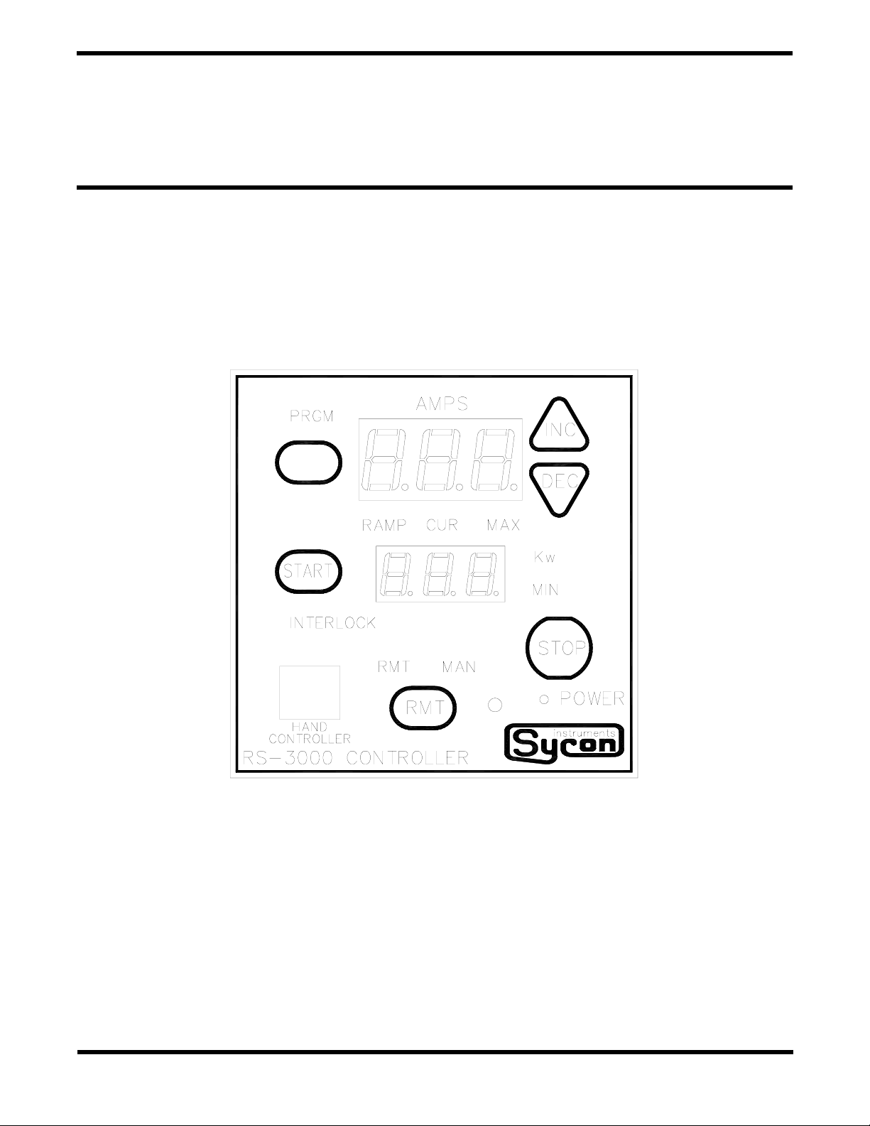
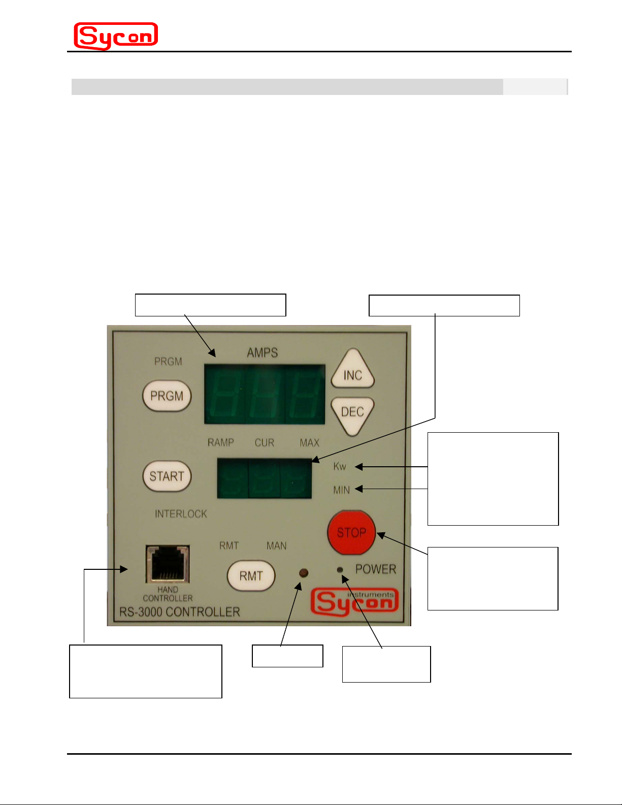
The RS-3000 functions as a user interface for the T3000 resistive power supply, and
supplies the control voltages needed to operate the T3000. The RS-3000 also displays
system faults in text message form or by indicator LEDs.
The RS-3000 can be controlled from the front panel, with a hand controller (or pendant), or
via the back-panel RS-232 connection.
Programmable parameters include: Maximum current, current ramp time, ramp current,
beeper control, and communication settings (mode, speed).
For uses requiring PID control loop capability, a remote control unit (such as the STC-2000)
can be connected to the RS-3000.
large 3 character displa
small 3 character displa
HAND CONTROLLER /
PENDANT
CONNECTOR [RJ-11]
BEEPER
Figure 1-1 RS-3000 Front Panel
POWER ON
INDICATOR
LED illuminated text
indicators (9 places):
PRGM, RAMP, CUR,
MAX, Kw, MIN,
INTERLOCK, RMT,
MAN
Pushbutton Keys
(6 places):
PRGM, INC, DEC,
START
RMT, STOP
Section 1
Page 1 - 1
Description of Equipment
Page 9

RS-3000
[
]
Power Supply Controller
To T3000 POWER
SUPPLY
15 pin D-SUB MALE
instruments
RS232/485
com port
[RJ-11]
Grounding
Stud
To ext. control (STC-
2000)
[15 pin D-SUB FEMALE]
Figure 1-2 RS-3000 Back Panel
Description of Equipment
Page 1 - 2
Section 1
Page 10

instruments
Power Supply Controller
RS-3000
Section 2
Connections
There is a 15 pin d-sub male connector at the back of the unit that is used to connect to
the T3000 power supply.
The RS-3000 is powered by the T3000 power supply.
There is a 15 pin d-sub female connector at the back of the unit that is used to connect
the RS-3000 unit to a more sophisticated control unit (such as the STC-2000).
There is a 6 pin modular connector (RJ-11) at the back of the unit for RS232/485
communication. This allows remote control of the RS-3000 by a PC.
There is a 6 pin modular connector (RJ-11) at the front of the unit for a hand controller.
The standard hand controller cord length is 6 feet when the coiled cord is fully extended.
Front Panel Interface
There are 6 front panel keys that are used to program the unit, change modes, and
start/stop the unit.
There are two 3 character displays.
The larger display is located near the top of the front panel.
The smaller display is located near the center of the front panel.
The larger display can show: mode (such as O.F.F. or Err), ramp current, and current.
If problems occur, an Error message is indicated by the letters Err appearing in the
larger display.
In program mode (current or new values can be seen or set): max current, ramp
current, beeper [on/off], speed, and address.
The smaller display can show: minutes and kilowatts
If problems occur, an error message is shown on the smaller display.
Examples are: Opn (for open boat) or Hot (for power supply over temperature
condition).
In program mode (existing or new values can be seen or set): ramp minutes,
[beeper] on/off, etc.
There are 9 LED illuminated indicators. Some indicators show the mode status: PRGM
(for program mode), RMT (for remote mode), and MAN (for manual mode). Other
indicators are associated with and show the value type of the data shown on the displays.
For example, with the first press of the program key (PRGM) the large display shows a
value, and the CUR and MAX LED indicators are illuminated. This indicates that the value
shown on the large display is the maximum current. With the second press of the program
Section 2
Page 2 - 1
Connections
Page 11

RS-3000
Power Supply Controller
instruments
key (PRGM) the large display is blanked while the small display shows a value. The LED
indicators that are illuminated now include the RAMP and MIN LEDs. This indicates that
the value shown on the small display is the ramp minutes. With the third press of the
program key (PRGM) the small display is blanked while the large display shows a value.
The LED indicators that are illuminated now include the RAMP and CUR LEDs. This
indicates that the value shown on the large display is the ramp current. In these cases, the
INC and DEC keys are used to set the values as needed. The program (PRGM) key
sequences through the programmable elements with each subsequent press until all
elements have been shown. In the programming mode, the program mode LED is
illuminated and flashing. When the program mode LED turns off the last of the
programmable elements is no longer shown and displays revert to the mode context from
which the program mode was launched.
Front Panel Interface
Page 2 - 2
Section 2
Page 12

instruments
Power Supply Controller
RS-3000
Section 3
Specifics
3.1 Program mode
Press PGRM key to enter the programmable parameter sequence.
The PGRM LED illuminates and flashes to indicate activity within the programming mode.
All programmable elements are modified by pressing the INC and DEC keys.
Table 3-1 Programmable Elements
Programmable element Where shown LED indicators/display Sequence element no.
maximum current large display CUR, MAX 1 (see descriptions below)
ramp minutes small display RAMP, MIN 2
ramp current large display RAMP, CUR 3
beeper (on/off) small display text bpr (large display) 4
comm. speed small display text Spd (large) 5
address small display text Adr (large) 6
Maximum current
number values in the range of 0-600 Amps (parallel wired outputs) or 0-300 Amps (series
wired outputs).
Ramp minutes: The INC/DEC keys increment and decrement through a sequence of
number values in the range of 0.0-99.9 minutes.
Ramp current
number values in the range of 0-600 Amps (parallel wired outputs) or 0-300 Amps (series
wired outputs).
Beeper on/off
Communication speed
of number values: 9600 baud, 38400 baud, and 115000 baud.
Address
: The INC/DEC keys increment and decrement through a sequence of number
values in the range of 0-9. RS232 is address 0 (hex address 0X10), and RS485 are
addresses 1-9 (hex addresses X52 – X5A).
All of the above elements are saved in non-volatile memory. To purge and set NV memory
to factory default values, press PRGM/DEC/RMT keys on power up (text message appears
to indicate default successful).
3.2 Manual mode
Whether the RS-3000 is in manual mode or ramp mode is determined by the
programmable value of ramp minutes. If ramp minutes is at zero, that is, 0.0, then manual
: The INC/DEC keys increment and decrement through a sequence of
: The INC/DEC keys increment and decrement through a sequence of
: The INC/DEC keys toggle between the values of on and off.
: The INC/DEC keys increment and decrement through a sequence
Section 3
Page 3 - 1
Specifics
Page 13

RS-3000
Power Supply Controller
instruments
mode will be entered when the start key is pressed. This is confirmed by the illumination of
the MAN LED indicator.
In the manual mode, the AMPS value shown in the large display can be varied using the
INC and DEC keys on the front panel or pendant. The AMPS value displayed is the basis
for what is requested from the power supply. Meanwhile, the small display alternately
shows Kilowatts and minutes. The Kilowatts value is the power being expended at the
supply output. The time value is the elapsed time from the press of the start key. The
Kilowatts and time values are differentiated by the illumination of either the Kw or MIN
LEDs. Pressing the stop key ends the manual mode which is confirmed by the display of
the text O.F.F. in the large display. The pendant stop key is equivalent to the front panel
stop key. Pressing the stop key places the RS-3000 into a quiescent state where the power
output ON/OFF signal to the T3000 is set to OFF (see section 10.1, pin 13) and the RS3000 analog output to control the T3000 power output is set to zero (see section 10.1, pin
7).
3.3 Ramp mode
Whether the RS-3000 is in manual mode or ramp mode is determined by the value of ramp
minutes. If ramp minutes is at a non-zero value, that is, any value but 0.0, then ramp mode
will be entered when the start key is pressed. This is confirmed by the fact that the MIN
value is counting down and that the MAN LED is not illuminated. Ramp mode does not
have a specific LED indicator.
In the ramp mode, the AMPS value shown in the large display changes based on the
programmed values of ramp current and ramp minutes. The AMPS value displayed is the
basis for what is requested from the power supply. Meanwhile, the small display alternately
shows Kilowatts and minutes. The Kilowatts value is the power being expended at the
supply output. The time value is the remaining time until ramping terminates at the desired
current. The Kilowatts and time values are differentiated by the illumination of either the Kw
or MIN LEDs. Pressing the stop key ends the ramp mode which is confirmed by the display
of the text O.F.F. in the large display. If the stop key is not pressed, the MINutes value will
count down to zero (while the power ramps up to the programmed value) and then the unit
will automatically go into the manual mode after zero minutes remaining has been
achieved. When in the manual mode the MINutes time will advance indefinitely at the last
power level set during the ramp mode.
Pressing the stop key during the RAMP mode or in the subsequent Manual mode, places
the RS-3000 into a quiescent state where the power output ON/OFF signal to the T3000 is
set to OFF (see section 10.1, pin 13) and the RS-3000 analog output to control the T3000
power output is set to zero (see section 10.1, pin 7).
3.4 Remote mode
This mode uses a remote controller (such as the STC-2000) to control the power supply
output.
Pressing the RMT key puts the unit into the remote mode. This is confirmed by the
illumination of the RMT LED. Pressing the RMT key again takes the unit out of the remote
Specifics
Page 3 - 2
Section 3
Page 14

instruments
Power Supply Controller
RS-3000
mode. During the remote mode, only Kilowatts and AMPS are shown. The stop key on the
front panel or pendant can also be used to cancel the remote mode.
The connection to the RS-3000 from the remote controller is through a 15 pin female DSUB connector on the back panel.
3.5 Error/problem Conditions
3.5.1 Interlock: is indicated by the illumination of the INTERLOCK LED on the front panel.
This indicates that continuity of the interlock system is open. The T3000 power
supply will not be controlled until this condition has been satisfied with a digital low
or ground (see section 3.6.10.2, pin# 3).
3.5.2 Open boat: indicated on the large and small displays in terse text as Err Opn (error
open). Indicates an open boat. This condition must be sensed after power is
applied and therefore a reset on the power supply can take a while to re-sense the
open boat condition. The T3000 power supply will not be controlled until this
condition has been satisfied with a digital low or ground (see section 3.6.10.1, pin#
1).
3.5.3 Over temperature: indicated on large and small displays in terse text as Err Hot
(error hot). Indicates an over temperature condition within the power supply. This
condition is sensed immediately and will not allow a reset on the power supply to
properly reset until the temperature has returned to a normal temperature range.
The T3000 power supply will not be controlled until this condition has been satisfied
with a digital low or ground (see section 3.6.10.1, pin# 9).
3.5.4 OOP: when indicated on both the large and small displays, this means that the
system has encountered a microcontroller induced reset from which it has
recovered. Condition indicates possible memory or microcontroller failures.
3.5.5 Err/PrG: indication for NV mem default due to error. This error condition can be
cleared by pressing the PRGM key.
3.5.5 Current maximum: when the requested current reaches the maximum value, the
MAX LED indicator blinks.
3.6 Hardware Specifics
3.6.1 Size:
7/8
3
inches wide X 3
3/4
inches high X 5
5/8
inches deep.
Rack mountable next to the T3000 power supply
3.6.2 Weight:
1.1 pounds
3.6.3 Voltage / Current requirements:
800 mA (290 mA quiescent in O.F.F. mode) for +5 VDC,
Section 3
Page 3 - 3
Specifics
Page 15

RS-3000
Power Supply Controller
2 mA for +12 VDC (use Sycon approved power supply only)
3.6.4 Beeper:
Audible (when enabled) in the 80-90 decibel range @ ~2.5 KHz
3.6.5 Case:
Aluminum with a grounding stud which is common to all connector shields.
Shield/case ground is interconnected to RS-3000 digital ground within the product
with a 1kΩ resistor.
3.6.6 Hand controller/pendant:
Has a 6 ft. coiled cord. Has an RJ-11 connector at one end and at the other end, a
module having 3 keys for remote useage of front panel keys: INCrement(↑),
DECrement (↓) and STOP. This assembly is supplied by Sycon Instruments.
Connects to RJ-11 connector on the front panel.
3.6.7 Communications cable (optional):
A six ft. coiled cord terminated with an RJ-11 at one end (mates with RS-3000 back
panel connector [RJ-11]) and a 9 pin female D-SUB at the other (RS232/485 port).
This assembly is supplied by Sycon Instruments. Used to interconnect the RS-3000
control unit with an RS232/485 port such as, what may be found on a PC. Using
communication software on the PC, the RS-3000 can be controlled as if by front
panel controls and interrogated as if observing the displays and LEDS.
3.6.8 RS-3000/T3000 Interconnect cable:
A 3 ft. or 6 ft. cable assembly, wired straight-through (that is, pin 1 to pin 1, pin 2 to
pin 2, etc.) terminated at the RS-3000 side with a 15 pin female D-sub and with a 15
pin male D-Sub connector at the T3000 side. This assembly is supplied by Sycon
Instruments. It is used to interconnect the T3000 power supply and the RS-3000
control unit (T3000 control connector).
3.6.9 RS-3000/STC-2002 Interconnect cable:
A 6 ft. cable assembly terminated at the RS-3000 side with 15 pin male D-SUB
connector and with a 15 pin female D-SUB connector on the T3000 side. It is
interconnected from the RS-3000 external control connector to the STC2000A/STC2002 control outputs connector.
instruments
Specifics
Page 3 - 4
Section 3
Page 16

instruments
Power Supply Controller
3.6.10 Description of the RS-3000 I/O:
Table 3-2 Back-panel 15-pin D-sub Male Pin Descriptions
PIN
NUMBER
1 When this line is high, the RS-3000 will indicate an Open Boat
2 Along with pin 10, this line provides the RS-3000 with +5 VDC
3 Along with pin 11, this line provides the RS-3000 with digital
4 Monitors the voltage output from the T3000 power supply
5 Alternative to T3000 Reset button (falling edge, not level
6 For future use, not implemented in software. Input
DESCRIPTION of Connector Labeled T3000 Control I/O
failure
power
ground
( 1 VDC = 1.5 VRMS )
sensitive)
direction
Input
w/ pull-up
Input
power
Input
power
Input
Output
w/ pull-up
RS-3000
7 A control voltage from the RS-3000 used to set the output
amperage of the T3000 (see note
8 Not connected N. A.
9 When this line is high, the RS-3000 will indicate an Over
Temperature failure
10 Along with pin 2, this line provides the RS-3000 with +5 VDC
power
11 Along with pin 3, this line provides the RS-3000 with digital
ground
12 This line provides the RS-3000 with +12 VDC power Input
13 A digital control voltage from the RS-3000 used to switch the
T3000 power supply output ON (w/ a digital low) or OFF (w/ a
digital high)
14 This line tells the RS-3000 how to interpret the T3000 data: as
series wired or parallel wired. Digital high = series, digital low =
parallel.
15 Monitors the amperage output of the T3000 ( 1 VDC = 100 Amps
RMS when parallel wired / 50 Amps RMS when series wired
1
Note
: 10 VDC = 600 AMPs parallel wired [or 300 AMPs series] and has a linear relationship down to zero except for a
small value range between zero volts and a small fraction of a volt where AMPs will remain at zero.
1
)
Output
Input
w/ pull-up
Input
power
Input
power
power
Output
w/ pull-up
Input
w/ pull-up
Input
Section 3
Page 3 - 5
Specifics
Page 17

RS-3000
Power Supply Controller
Table 3-3 Back-panel 15-pin D-sub Female Pin Descriptions
PIN
NUMBER
1 Analog ground of the RS-3000 presented to remote controller
2 Along with pin 10, this line presents the RS-3000 digital ground to
3 Interlock status indication: grounded (to pin 2) or digital low =
4 Process abort (digital low = process abort) Input
5 Process START event (digital falling edge = START event) Input
6 Fault reset (digital falling edge = reset event) Input
7 Remote out (digital high = remote enabled) Output
8 Ready (digital high = ready enabled) Output
9 Voltage control (remote voltage control, via RS-3000, of the
10 Along with pin 2, this line presents the RS-3000 digital ground to
11 Process timer reset (digital falling edge = reset event) Input
12 Process STOP event (digital falling edge = STOP event) Input
13 Remote/Local START mode Input
14 Busy (digital high = active) Output
15 Fault (digital high = active) Output
DESCRIPTION of Connector Labeled External Control I/O
Direction
ground
(used with Voltage control [pin #9])
the remote controller
satisfied, open or digital high = interlock error (indicated by front
panel LED)
T3000)
the remote controller
pass thru
ground
pass thru
Input
w/ pull-up
w/ pull-up
w/ pull-up
w/ pull-up
w/ pull-up
w/ pull-up
Input
ground
pass thru
w/ pull-up
w/ pull-up
w/ pull-up
w/ pull-up
w/ pull-up
instruments
Specifics
Page 3 - 6
Section 3
Page 18

instruments
Power Supply Controller
RS-3000
Section 4
Specifics
4.1 Events and modes
Various events cause mode changes. Events can include: elapsed time decremented to
zero, amperage reaching a programmed value, an over-temperature condition, an open
boat condition, loss of interlock continuity, or user interaction with front panel or pendant
keys.
Following are specific events and their effects on the various modes.
Table 4-1 Manual Mode
Event From To Description
START key O.F.F. mode MAN mode Starts Manual mode if user programmed ramp minutes
equals zero. MAN indicator is illuminated. The large display
shows requested current from the T3000. The INC and DEC
keys are used to change the requested value that is
displayed. The pendant arrow keys provide this same
function. The small display shows alternating minute and
kilowatt values. Minute and kilowatt values can be
differentiated by the illumination of the Kw and MIN
indicators and by the position of the decimal point (x.xx=Kw
format / xx.x=MIN format). In Manual mode, the time counts
up, measuring elapsed time. Upon entry into the Manual
mode, previous elapsed time values, if any, are reset to
zero.
INC + DEC MAN mode
minutes > 0
INC MAN mode
AMPs [value]
DEC MAN mode
AMPs [value]
STOP MAN mode O.F.F. mode Ends Manual mode. The pendant STOP key provides this
err: open
boat
err: hot MAN mode O.F.F. mode Error ends Manual mode.
INTERLOCK MAN mode O.F.F. mode Interlock at logical high ends Manual mode.
MAN mode O.F.F. mode Error ends Manual mode.
MAN mode
minutes = 0
MAN mode
AMPs
[value]+1
MAN mode
AMPs
[value]-1
Elapsed time can be reset to zero by pressing both the INC
and DEC keys simultaneously. The pendant arrow keys
provide this same function.
Amperage requested can be incremented by pressing the
INC key. The pendant arrow up key provides this same
function. (Large display labeled AMPS)
Amperage requested can be decremented by pressing the
DEC key. The pendant arrow down key provides this same
function. (Large display labeled AMPS)
same function.
Section 4
Page 4 - 1
Specifics
Page 19

RS-3000
Power Supply Controller
instruments
Table 4-2 Ramp Mode
Event From To Description
START key O.F.F. mode RAMP mode Starts Ramp mode if user programmed
ramp minutes does not equal zero. The
large display shows requested current from
the T3000. The requested current value is
based upon the user programmed values
of Ramp current and Ramp minutes. The
Ramp current is divided across the Ramp
minutes and is distributed in a linear
progression increasing from zero to the
user programmed value of Ramp current
just as the Ramp minutes value is reached.
For example, at 25% of elapsed time, the
current request will be at 25% of the
programmed value of Ramp current. The
small display shows alternating minute and
kilowatt values. Minute and kilowatt values
can be differentiated by the illumination of
the Kw and MIN indicators and by the
position of the decimal point (x.xx=Kw
format / xx.x=MIN format). Upon entry into
the Ramp mode, the time counts down
from the user programmed value of Ramp
minutes, measuring remaining time until
zero is reached.
Ramp minutes=0 RAMP mode MAN mode Ends Ramp mode and automatically starts
the Manual mode (see Manual mode
START).
STOP key RAMP mode O.F.F. mode Ends Ramp mode. The pendant STOP key
provides this same function.
START key RAMP mode MAN mode Ends Ramp mode and automatically starts
the Manual mode (see Manual mode
START) retaining the last current value
held in the Ramp mode.
Err: open boat RAMP mode O.F.F. mode Error ends RAMP mode.
Err: hot “ O.F.F. mode “
INTERLOCK RAMP mode O.F.F. mode Interlock at logical high ends RAMP mode.
Specifics
Page 4 - 2
Section 4
Page 20

instruments
Power Supply Controller
RS-3000
Table 4-3 Remote Mode
Event From To Description
RMT key O.F.F. mode REMOTE mode Starts Remote mode. RS-3000 needs to be
connected to an STC-2000 or equivalent. The large
display shows current and the small display shows
kilowatts. The RMT indicator is illuminated.
RMT key REMOTE mode MAN mode Toggles Remote mode off and automatically starts
the Manual mode (see Manual mode START)
retaining the last current value held in the Remote
mode. As previously described for the START key
event entering Manual mode, the large display shows
current and the small display alternates between
showing kilowatts and minutes. The RMT indicator is
now off and the MAN indicator is illuminated.
STOP key REMOTE mode O.F.F. mode Ends Remote mode. The pendant STOP key
provides this same function.
Table 4-4 Program Mode
Event From To Description
PRGM key any mode (except
the PRGM mode)
PRGM key PRGM mode PRGM mode For the 2nd press of the PRGM key while in the
PRGM mode Starts Program mode. The PRGM indicator blinks
while in the Program mode. The first in a
sequence of six user programmable parameters is
shown (that of maximum current). The INC/DEC
keys provide the means to make a value change.
Program sequence, Ramp minutes can be altered
by the INC/DEC keys (range is 0-99.9 minutes).
For the 3rd press of the PRGM key while in the
Program sequence, Ramp current can be altered
by the INC/DEC keys (range is 0-600 Amps). For
the 4th press of the PRGM key while in the
Program sequence, beeper configuration can be
altered by the INC/DEC keys (select: ON or OFF).
For the 5th press of the PRGM key while in the
Program sequence, communication speed can be
configured by the INC/DEC keys (9.6, 38.4 or 115
kbaud). For the 6th press of the PRGM key while in
the Program sequence, address can be
configured by the INC/DEC keys (0-9). The 7
press of the PRGM key while in the Program
sequence, terminates the PRGM mode and the
PRGM indicator ceases to blink. Parameters are
saved immediately as they are entered (there is
no quit without saving). If there is a lack of activity
for 30 seconds during the programming sequence,
the programming mode will auto-terminate.
th
Section 4
Page 4 - 3
Specifics
Page 21

RS-3000
Power Supply Controller
no yes
O.F.F. mode
Manual mode
(press START w/0
time)
Power up:
Version
In Remote
mode?
Remote mode
Ramp mode
(press START w/ time)
Figure 4-1 Mode Navigation
Display until corrected:
Overheated PS (Err Hot) PS
w/Open boat (Err
Remote mode
(press RMT key)
Opn)
instruments
Specifics
Page 4 - 4
Section 4
Page 22

instruments
Power Supply Controller
RS-3000
always accessible
(press PRGM key)
Program mode
(PRGM LED illuminates)
INC/DEC
INC/DEC
INC/DEC
(press PRGM key)
To exit Program mode
(PRGM LED extinguishes)
Max power
(press PRGM key)
Ramp Current
(press PRGM key)
Comm.
speed
JM 17JAN2002
(press PRGM key)
Ramp time
(press PRGM key)
Beeper
functionality
(press PRGM key)
Comm.
Address
INC/DEC
INC/DEC
Figure 4-2 Program Mode Navigation
Section 4
Page 4 - 5
Specifics
Page 23

RS-3000
Power Supply Controller
instruments
Specifics
Page 4 - 6
Section 4
Page 24

instruments
Power Supply Controller
RS-3000
Section 5
Service
The unit is best opened by removing the 4 back panel screws then the four connector
securing hardware (capturing) standoffs. Remove back panel. Remove top by sliding it
rearward. Slide main board rearward to remove (note connection to front panel board) or
service the fuses or jumpers without removing main board. Take care not to touch
electronic devices or circuitry such that a high voltage discharge path from your finger may
develop and destroy components.
There are 2 socketed internal fuses. One for VCC (labeled F1) and the other for +12 volts
(labeled F2).
The RS-3000 power-on event sequence is as follows. The green power LED is illuminated.
Next, the unit momentarily illuminates all LEDs and display segments. Then it momentarily
displays its software version number (large display) and 300 (T3000 wired in series) or 600
(T3000 wired in parallel) in the small display. If the number displayed does not match the
actual configuration, check the wiring select switch on the T3000. If there are no error
conditions, the RS-3000 will display 0.F.F. in the large display.
Section 5
Page 5 - 1
Service
Page 25

RS-3000
Power Supply Controller
instruments
Service
Page 5 - 2
Section 5
Page 26

instruments
Made in the U.S.A
Sycon Instruments
6757 Kinne Street
East Syracuse, New York 13057-1215
V (315) 463-5297 F (315) 463-5298 info@sycon.com
 Loading...