


 Loading...
GB
ES
DE
FR
Operator’s manual
Please read the operator’s manual carefully and make sure you understand the instructions before using the machine.
Manual de instrucciones
Lea detenidamente el manual de instrucciones y asegúrese de entender su contenido antes de utilizar la máquina.
Bedienungsanweisung
Lesen Sie die Bedienungsanweisung sorgfältig durch und machen Sie sich mit dem Inhalt vertraut,bevor Sie das Gerät benutzen.
Manuel d’utilisation
Lire attentivement et bien assimiler le manuel d’utilisation avant d’utiliser la machine.
WS 463
GB ES DE FR
HUSQVARNA CONSTRUCTION PRODUCTS
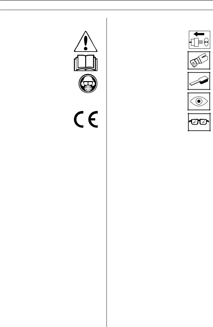
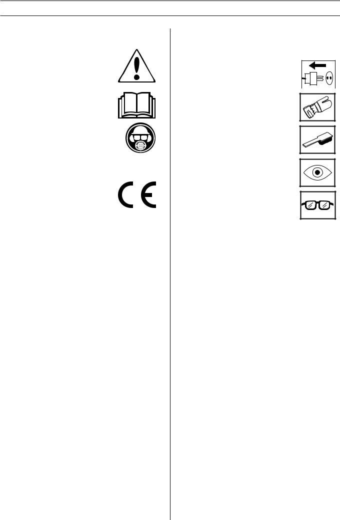
KEY TO SYMBOLS
Symbols on the machine:
WARNING! The machine can be a dangerous tool if used incorrectly or carelessly, which can cause serious or fatal injury to the operator or others.
Please read the operator’s manual carefully and make sure you understand the instructions before using the machine.
Always wear:
•Approved protective helmet
•Approved hearing protection
•Protective goggles or a visor
•Breathing mask
This product is in accordance with applicable EC directives.
Symbols in the operator’s manual:
Inspection and/or maintenance should be carried out with the motor switched off and the plug disconnected.
Always wear approved protective gloves.
Regular cleaning is required.
Visual check.
Protective goggles or a visor must be worn.
2 – English

|
CONTENTS |
Contents |
|
KEY TO SYMBOLS |
|
Symbols on the machine: ............................................. |
2 |
Symbols in the operator’s manual: ............................... |
2 |
CONTENTS |
|
Contents ...................................................................... |
3 |
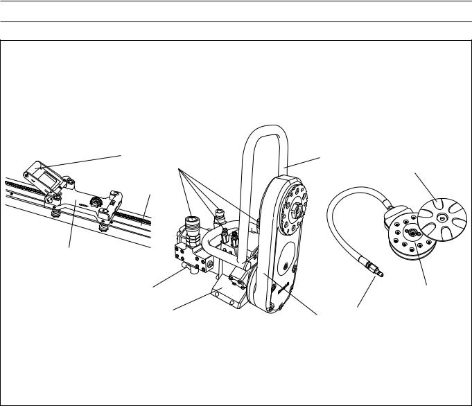
WHAT IS WHAT? |
|
What is what on the wall saw? ..................................... |
4 |
SAFETY INSTRUCTIONS |
|
Steps before using a new wall saw .............................. |
5 |
Personal protective equipment ..................................... |
5 |
General safety precautions .......................................... |
6 |
General working instructions ....................................... |
6 |
Basic working techniques ............................................ |
7 |
PRESENTATION |
|
WS 463 ........................................................................ |
8 |
ASSEMBLY |
|
Mount wall mountings and rail ..................................... |
9 |
Mount the saw carriage and saw ................................. |
10 |
Fit the blade ................................................................. |
10 |
Flush cutting ................................................................ |
11 |
Fit the blade guard ....................................................... |
11 |
Connect the hydraulic unit ........................................... |
12 |
STARTING AND STOPPING |
|
Before starting ............................................................. |
13 |
Starting ........................................................................ |
13 |
Stopping ....................................................................... |
13 |
Dismantling the saw ..................................................... |
13 |
Cleaning ....................................................................... |
13 |
SETTINGS AND ADJUSTMENTS |
|
Adjusting the guide wheels .......................................... |
14 |
Adjust the saw carriage ................................................ |
14 |
MAINTENANCE |
|
Service ......................................................................... |
15 |
Maintenance ................................................................ |
15 |
Daily maintenance ....................................................... |
15 |
TECHNICAL DATA |
|
WS 463 ........................................................................ |
16 |
EC-declaration of conformity ........................................ |
17 |
English – 3
WHAT IS WHAT?
2 |
|
10 |
6 |
9 |
|
|
|
||
|
|
|
|
|
|
7 |
|
|
|
1 |
|
|
|
|
|
4 |
|
|
8 |
|
|
|
|
|
|
3 |
|
5 |
11 |
|
|
|
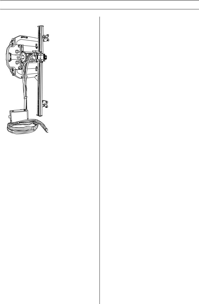
What is what on the wall saw?
1 |
Saw carriage |
7 |
Track |
2 |
Locking handle |
8 |
Blade flange hub |
3 |
Saw unit |
9 |
Outer blade flange |
4 |
Speed valve |
10 |
Hydraulic hose connections |
5 |
Cutting arm |
11 |
Water connector |
6 |
Blade guard guide |
|
|
4 – English
SAFETY INSTRUCTIONS
Steps before using a new wall saw
•Please read the operator’s manual carefully and make sure you understand the instructions before using the machine.
•This machine is designed for and intended for sawing concrete, brick and different stone materials. All other use is improper.
•This machine is only intended for use together with a Husqvarna PP 355, Husqvarna PP 455 and Husqvarna RC 455. All other use is forbidden.
•The machine is intended for use in industrial applications by experienced operators.
•Please read the operator´s manual supplied with the hydraulic unit before using the machine.
•The machine can cause serious personal injury. Read the safety instructions carefully. Learn how to use the machine.
Always use common sense
It is not possible to cover every conceivable situation you can face. Always exercise care and use your common sense. Avoid all situations which you consider to be beyond your capability. If you still feel uncertain about operating procedures after reading these instructions, you should consult an expert before continuing.
Do not hesitate to contact your dealer if you have any more questions about the use of the machine. We will willingly be of service and provide you with advice as well as help you to use your machine both efficiently and safely.
Let your Husqvarna dealer regularly check the machine and make essential adjustments and repairs.
All information and all data in the Operator’s Manual were applicable at the time the Operator’s Manual was sent to print.
WARNING! Under no circumstances should
!you modify the original design of the machine without approval from the manufacturer. Always use original spare parts. Unauthorised modifications and/or accessories may lead to serious injury or death to the user or others.
WARNING! Use of products which cut, grind,
!drill, sand or shape material can generate dust and vapors which may contain harmful chemicals. Know the nature of the material being worked on and wear appropriate dust mask or respirator protection.
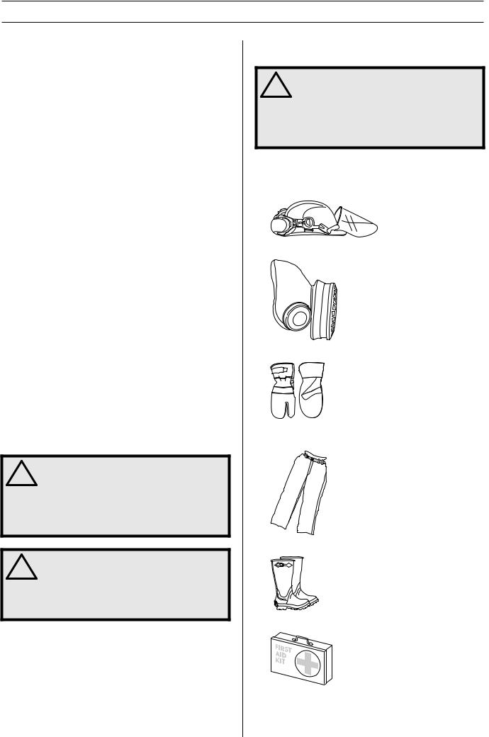
Personal protective equipment
WARNING! You must use approved personal
!protective equipment whenever you use the machine. Personal protective equipment cannot eliminate the risk of injury but it will reduce the degree of injury if an accident does happen. Ask your dealer for help in choosing the right equipment.
•Protective helmet
•Hearing protection
•Protective goggles or a visor
•Breathing mask
•Heavy-duty, firm grip gloves.
•Tight-fitting, heavy-duty and comfortable clothing that permits full freedom of movement.
•Boots with steel toe-caps and non-slip sole.
•Always have a first aid kit nearby.
English – 5

SAFETY INSTRUCTIONS
General safety precautions
Do not use the machine without first reading and understanding the contents of this Operator’s Manual.
WARNING! There is always a risk of crush
!injuries when working with products containing moving parts. Wear protective gloves to avoid body injuries.
•Never use the machine if you are tired, if you have drunk alcohol, or if you are taking medication that could affect your vision, your judgement or your co-ordination.
•Wear personal protective equipment. See instructions under the heading Personal protective equipment.
•Keep all parts in good working order and ensure that all fixtures are properly tightened.
•Never use a machine that is faulty. Carry out the checks, maintenance and service instructions described in this manual. Some maintenance and service measures must be carried out by trained and qualified specialists. See instructions under the heading Maintenance.
•Do not modify safety equipment. Check regularly that they function as they should.The machine must not be run with defective or disassembled safety equipment.
•Never allow anyone else to use the machine without first ensuring that they have understood the contents of the operator’s manual.
•People and animals can distract you causing you to lose control of the machine. For this reason, always remain concentrated and focused on the task.
•Be careful as clothing, long hair, and jewellery can get caught in moving parts.
•Observe care when lifting. You are handling heavy parts, which implies the risk of pinch injuries or other injuries.
Transport and storage
•Always switch off the power to the hydraulic unit and disconnect the hoses to the saw unit before moving the equipment.
•Dismount the blade and blade guard before transport and storage.
•Store the equipment in a lockable area so that it is out of reach of children and unauthorised persons.
•Use the cases provided to store the equipment.
General working instructions
WARNING! This section describes basic
!safety directions for using a wall saw. This information is never a substitute for professional skills and experience. If you get into a situation where you feel unsafe, stop and seek expert advice. Contact your dealer, service agent or an experienced user. Do not attempt any task that you feel unsure of!
•All operators shall be trained in the use of the machine. The owner is responsible for ensuring that the operators receive training.
•Check that the blade guard is not damaged and that it has been fitted correctly.
•Never use blades other than original blades designed for the machine. Check with your Husqvarna dealer to see which blades are best suited for your usage.
•Never use a damaged or worn blade.
•Never mount or dismount the blade or blade guard without first switching off the hydraulic unit and disconnecting the hydraulic hoses running to the saw unit.
•Never cut without using the blade guard.
•Check that the blade is not in contact with anything when the machine is started.
•Remain at a distance from the blade when the engine is running.
•Water cooling must always be used. This cools the blades and increases their life and prevents dust build-up.
•Check that all couplings, connections and hydraulic hoses are in full working order.
•Keep the hydraulic hoses and couplings free from dirt.
•Do not misuse hoses.
•Do not use hoses that are distorted, worn or damaged.
•Check that the hoses are connected correctly to the machine and that the hydraulic couplings lock as intended before pressurising the hydraulic system. The couplings are locked by turning the outer sleeve on the female coupling so that the slot moves away from the ball.
•Never use the hydraulic hoses to lift the saw.
•Check the machine, couplings and hydraulic hoses daily for leakage. A rupture or leak can cause a ”hydraulic fluid injection” in the body or result in other serious physical injury.
•Never disconnect the hydraulic hoses without first shutting off and disconnecting the hydraulic unit and ensuring the motors have stopped completely.
•Do not exceed the specified hydraulic fluid flow or pressure for the tool being used. Excessive pressure or flow can result in rupturing.
•Hoses that are marked and approved as electrically non conductive must be used when using hydraulic tools on or in the vicinity of electrical cables. The use of other types of hoses can result in serious physical injury or even death.
6 – English
SAFETY INSTRUCTIONS
•Run the hydraulic system until it reaches its operation temperature of 30°C before starting to saw, to reduce return pressure and other wear.
•Clearly mark out all cuts to be made before you start sawing, plan these so they can be carried out without danger to persons or the machine.
•Firmly secure or anchor concrete blocks before cutting. The heavy weight of cut material can cause extensive damage if it is not moved under controlled conditions.
•Always check the back of the wall where the blade comes out when cutting through. Secure, cordon off and make sure that no people can be injured or materials damaged.
•Always check and mark out where gas pipes are routed. Cutting close to gas pipes always entails danger. Make sure that sparks are not caused when cutting in view of the risk of explosion. Remain concentrated and focused on the task. Carelessness can result in serious personal injury or death.
•Make sure that no pipes or electrical cables are routed in the area to be cut.
•Check that electrical cables within the working area are not live.
•Never leave the machine unsupervised with the engine running.
•Never saw in such a way that you cannot easily reach the emergency stop on the hydraulic unit orthe stop button on the remote control. See hydraulic unit manual.
•Make sure that there is always another person close at hand when you use the machines, so that you can call for help if an accident should occur.
•People that need to be in close proximity of the machine must wear hearing protection as the sound level when cutting exceeds 85 dB(A).
•Make sure that no people or animals come closer than 4 m (15 ft) when the machine is running.
•Do not use the machine in bad weather, such as dense fog, rain, strong wind, intense cold, etc. Working in bad weather is tiring and can lead to dangerous conditions, e.g. slippery surfaces.
•Ensure that the working area is sufficiently illuminated to create a safe working environment.
•Always ensure you have a safe and stable working position.
•Observe care when lifting. You are handling heavy parts, which implies the risk of pinch injuries or other injuries.
WARNING! Never use a blade for any other
!materials than that it was intended for.
Operating saw blades at rotational speeds greater than those recommended by the manufacturer can cause blade damage and possibly subsequent injury. See the Technical data section.
Basic working techniques
•Always start by cutting a pilot cut. This is done by feeding the blade 3-7 cm (1,2”-2,8”). Now make the pilot cut. The cut should not be made at maximum speed, but with care in order to obtain a straight cut and with that a basis for the next cut. The cutting arm allows blades up to 1 000 mm (40”) to be used as the start blade. It is, however, recommended to start cutting with an 800 mm (31.5”) blade.
•When the pilot cut is finished, a deeper cut can be made. The depth of these is determined from instance to instance and depends on factors such as hardness of the concrete, existence of reinforcing bar, etc. Max. diameter of the blade for deeper cuts is 1,600 mm (63”).
•If you change blades to cut deeper in the same cut, make sure the thickness of the blade matches the width of the groove.
•Let the machine work without forcing or pressing the blade.
•Firmly secure or anchor concrete blocks before cutting. The heavy weight of cut material can cause extensive damage if it is not moved under controlled conditions.
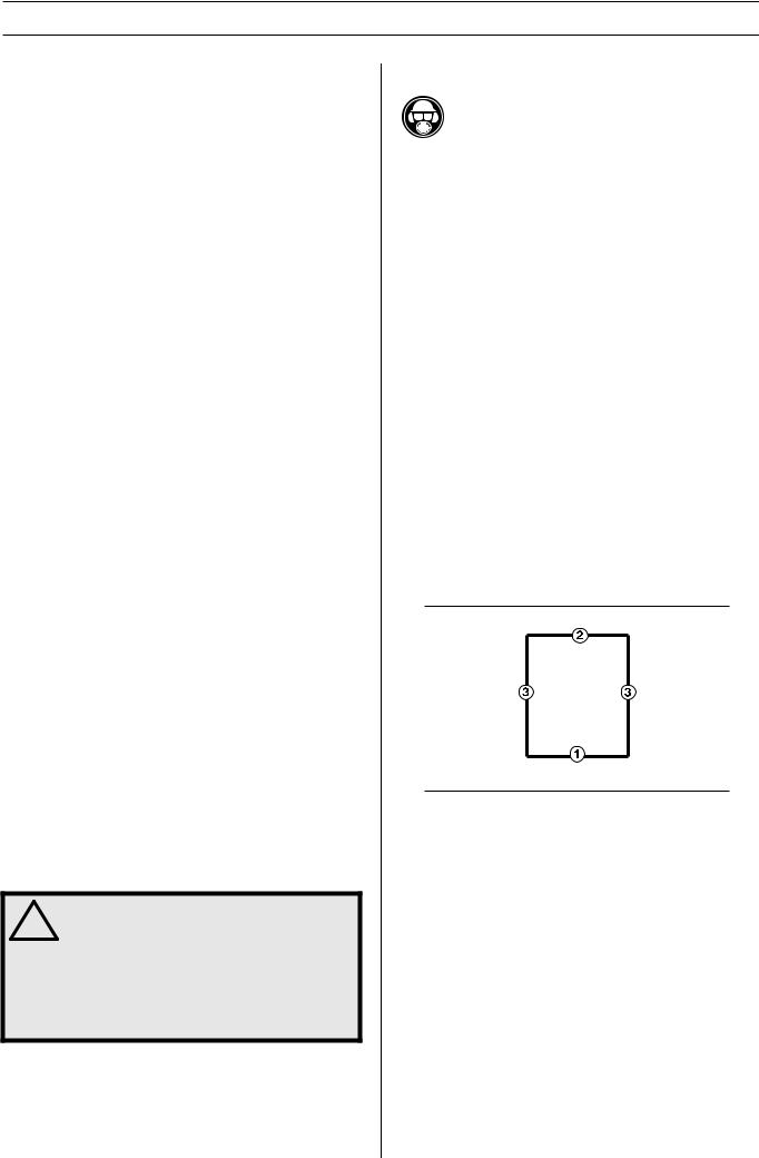
Cutting of blocks
•First make the lower horizontal cut. Now make the upper horizontal cut. Finish with the two vertical cuts.
•If the upper horizontal cut is made before the lower horizontal cut, the work piece will fall on the blade and jam it.
•When making the last cut, the saw should be mounted on an adjacent fixed wall.
•As the rail is symmetrical, the saw unit can be turned to make a new cut on the other side of the rail. In this way a cut piece is obtained that is in an easily handled size, making it easier to remove from the workplace.
•Since the blade rotation direction can be selected, the water spray from the blade can also be selected regardless of how the saw is turned on the rail.
English – 7
PRESENTATION
WS 463
It is our wish that you will be satisfied with your product and that it will be your companion for a long time. Think of this operator′s manual as a valuable document. By following its′ content (using, service, maintenance etc) the life span and the second-hand value of the machine can be extended. If you will sell this machine, make sure that the buyer will get the operator′s manual.
A purchase of one of our products gives you access to professional help with repairs and services. If the retailer who sells your machine is not one of our authorised dealers, ask him for the address of your nearest service workshop.
Husqvarna Construction Products has a policy of continuous product development. Husqvarna reserves the right to modify the design and appearance of products without prior notice and without further obligation introduce design modifications.
General
WS 400 is a series of completely new complete wall saws from Husqvarna. The intention when developing the Husqvarna WS 400 series has been to produce a very light yet powerful wall saw that is easy for one person to handle using modern production methods and high performance materials.
Among the new features on the WS 400 series is the possibility to secure the blade radially on the saw. As the saw unit is mounted on a carriage using a quick-action mounting instead of directly on the rail, assembly of the saw is significantly easier.
To utilises the input effect in the best possible way the saw is mounted on Husqvarna’ the latest rail. This is a very stable rail, which allows the saw to be controlled more precisely, which in turn results in more efficient cutting. As the equipment’s component parts work with small losses and as the blade is moved in 50 mm closer to the rail compared to earlier models, which has also resulted in a saw with an extremely compact design and at the same time as efficiency has increased.
Complete saw equipment consists of:
•One saw
•One track 1.2 m
•One track 2 m
•Four wall mountings
•One track holder
•One connector
•One blade guard 800 or one blade guard 1000
•One blade guard guide
•One tool kit
•One bottle of Husqvarna oil 150
Transport cases for the different units The saw carriage is mounted on both the long and short rails at the factory to make cutting as easy as possible.
As a large part of the sawing work consists transporting, the saw equipment is supplied in specially produced cases. The cases provide good protection during transport and reduced the number of packages that need to be moved between the workplaces, which makes the work more effective.
8 – English
ASSEMBLY
Mount wall mountings and rail
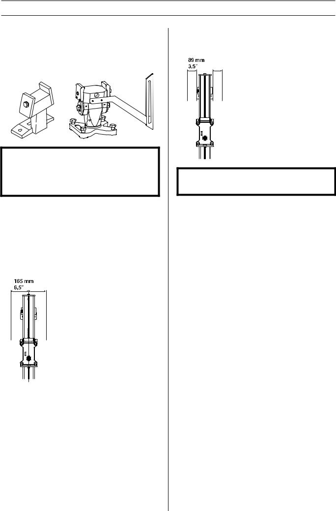
There are two types of wall mounting available for the Husqvarna WS 400 series. One, the standard wall mounting, which is supplied on delivery, and secondly the universal swivel wall mounting.
IMPORTANT! The Husqvarna WS 400 series may only be used with the two wall mountings described above. Older Husqvarna wall mountings are similar to the new standard wall mounting, but have a longer base. This mounting must not be used with the WS 400 series as there is a risk that the arm catches on the base of the mounting.
Use the universal wall mounting when cutting doors, cutting flush, cutting at angles and stair cutting as well as groove cutting. If you only require an everyday straight cut you use the fixed mounting.
Fit the universal wall mounting for the required cutting method (See the separate manual).
Fit the standard wall mounting as set out below:
1Mark off the cutting line and mark off the expander bolts holes 165 mm (6.5") from the cutting line.
2Drill 15 mm (5/8”) holes for the M12 (1/2”) expander bolts.
3Hang the wall mountings loosely from the expander bolts, using M6S 12 x 70 (1/2”x2”) or similar.
4Place the rail in the wall mountings and tighten the compression washers.
5Check that the rail is properly aligned with the tracks on the wall mounts before tightening the screws.
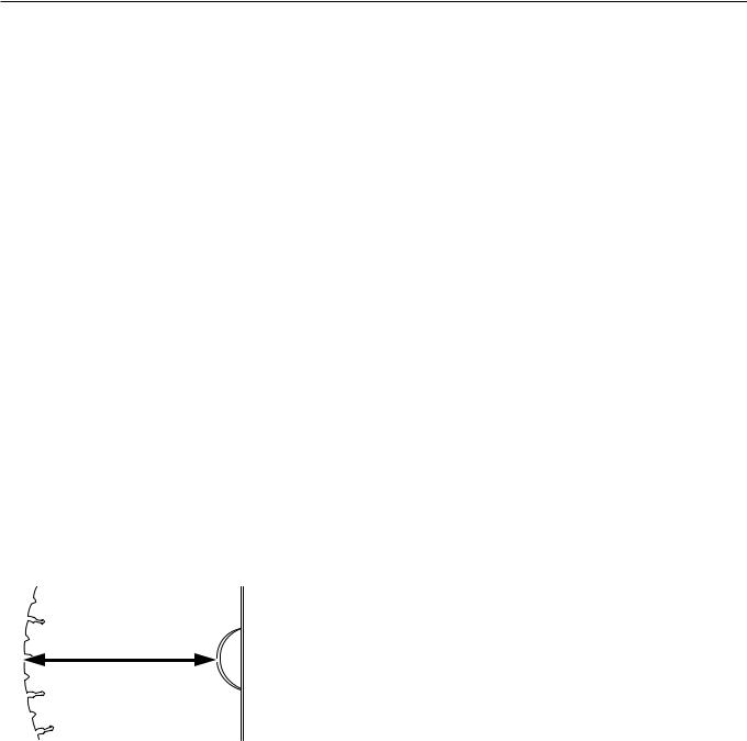
6Adjust the distance between the cutting line and the wall mounting. The distance between the edge and the inner face of the saw cut should be 89 mm (3.5"). Tighten the expander bolts.
IMPORTANT! Only use the connectors supplied when purchasing the saw as older connectors are not designed for the WS 400 series.
English – 9
ASSEMBLY
Mount the saw carriage and saw
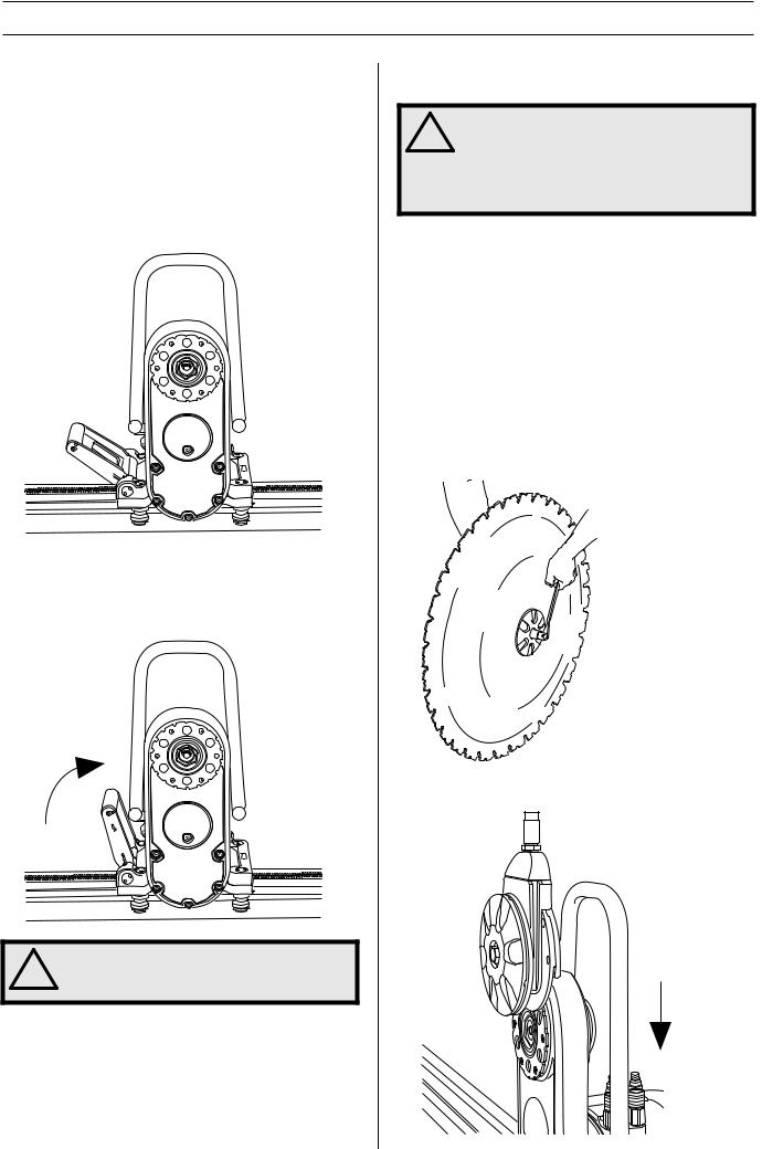
The saw carriage is mounted on the rail at delivery. The carriage can be dismounted from the rail by removing the end stop on the rail and pulling the carriage away.
1Fit the saw body in the saw carriage by lifting the saw body into position. When the saw is lifted into position, the locking handle moves up into an intermediate position. In this position the saw remains in the saw carriage without it needing to be held. However, it is not sufficiently secured to begin cutting.
For vertical cuts, the rail must be mounted with the saw carriage lock handle upwards. This to facilitate fitting the saw unit.
2To secure the saw, lift the locking handle towards the saw until the handle locks.
WARNING! To cut without the saw securely
!assembled in the saw carriage and rail is associated with mortal danger.
Fit the blade
WARNING! Never mount or dismount the
!blade or blade guard without first switching off the hydraulic unit and disconnecting the hydraulic hoses running to the saw unit.
Carelessness can result in serious personal injury or even death.
On the Husqvarna WS 400-series the blade is fitted in an entirely new way.The new mounting permits, in addition to the tradition way of securing the blade, the possibility to secure the blade radially both quickly and easily:
1Start by removing any dirt from the contact surfaces on the blade flange and blade.
2Check the blade’s direction of rotation. The blade should rotate anticlockwise seen from the saw side and the released part of the diamond should lie in the blade’s direction of rotation. Since the blade rotation direction can be selected, the water spray from the blade can also be selected regardless of how the saw is turned on the rail.
Screw together the outer blade flange, blade and blade flange hub (tightening torque 70-80 Nm).
3Hang the blade with the blade flange and blade flange hub fitted on the cutting arm (blade is not shown in the figure).
10 – English

ASSEMBLY
4Turn the blade flange hub carefully so that it slides into one of the tracks in the pivot arm and lands in the correct position to be screwed fast.
5Press in the blade spindle into the cutting arm at the same time as the blade is rotated carefully. When the blade spindle can no longer be pressed in by hand it should be tightened using the supplied 18-spanner until it is properly secured (tightening torque 70-80 Nm).
WARNING! Exercise care when assembling
!the blade so that it does not risk becoming loose when cutting. Carelessness can result in serious personal injury or even death.
Flush cutting
Screw off the outer blade flange and mount the blade on the blade flange hub.
A=110 mm/4.33 inch, 6xM10
B=89 mm/3.5 inch, 6xM8
C=144 mm/5.7 inch
Fit the blade guard
WARNING! Never mount or dismount the
!blade or blade guard without first switching off the hydraulic unit and disconnecting the hydraulic hoses running to the saw unit.
Carelessness can result in serious personal injury or even death.
1Slip in the blade guard guide between the stays on the blade guard. Place the blade guard guide in the middle. Lock the plastic heel on the handle to the upper stay on the blade guard.
2Make sure that the pivot arm is positioned vertically. Lift the blade guard over the blade and hang the guard in the blade guard holder on the saw. Exercise care so that the runners on the blade guard are positioned in the slots on the water block.
3Lock the blade guard by pulling the handle out of the guard and then down towards the saw unit so that the latch locks the handle.
English – 11
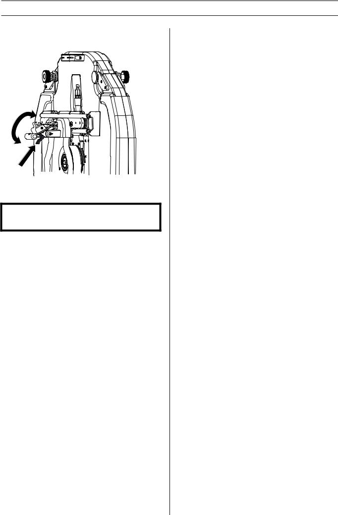
ASSEMBLY
4To remove the guard, release the latch and pull the handle upwards and inwards to the guard. Lock the plastic heel on the upper stay.
Connect the hydraulic unit
IMPORTANT! This machine is only intended for use together with a Husqvarna PP 355, Husqvarna PP 455 and Husqvarna RC 455. All other use is forbidden.
Please read the operator´s manual supplied with the hydraulic unit before using the machine.
When the saw unit, the blade and the blade guard are mounted, the hydraulic hoses and the water cooling should be connected.
There are two types of hydraulic hoses for the saw:
•The four thin hoses control the feed motors, i.e. the saw’s travel feed on the rail and the feed - removal of the blade. The two thick hoses drive the blade.
•The couplings should be wiped clean to reduce the risk of leakage before the hoses are fitted. Both the thin and thick hoses are locked by turning the outer sleeve on the female coupling so that the groove in the sleeve moves away from the ball.
12 – English
STARTING AND STOPPING
Before starting
•Enclose the area to be cut so that unauthorised persons can not be injured or disturb the operator.
•Check that the blade and th blade guard is not damaged or cracked. Replace the blade or the blade guard if it is exposed to impact or is cracked.
•Make sure that all hydraulic hoses and connections are intact and correctly connected, and that the water cooling is correctly connected and switched on.
•Check the oil level in the cutting unit. Adjust the speed valve on the saw motor to the correct position, depending on the blade diameter. (See the Cutting capacity table).
•If cutting is to begin in another position than where the saw unit is located, run the saw unit to the start position.
Starting
Follow the instructions for starting in the manual supplied with the hydraulic unit.
Stopping
•Once cutting is completed, remove the blade from the wall and shut down the blade rotation and the water flow.
•Shut down the hydraulic unit.
Dismantling the saw
1Allow the motor to stop completely.
2Disconnect the incomming cables from the hydraulic unit.
3Switch off the power to the hydraulic unit.
4Disconnect the hydraulic hoses and the water hose from the saw unit.
The other steps are done in the reverse order to assembling.
Cleaning
The saw should be cleaned once cutting is finished. It is important to clean all the saw equipment. It is a good idea to disconnect the water hose from the pivot arm and use this to wash down the saw unit, rail, blade guard, wall mounting. If necessary you can also use a dish-brush or the like to clean the equipment. Do not use a high pressure washer to clean the saw.
IMPORTANT! Do not use a high pressure washer to clean the saw.
English – 13
SETTINGS AND ADJUSTMENTS
Adjusting the guide wheels
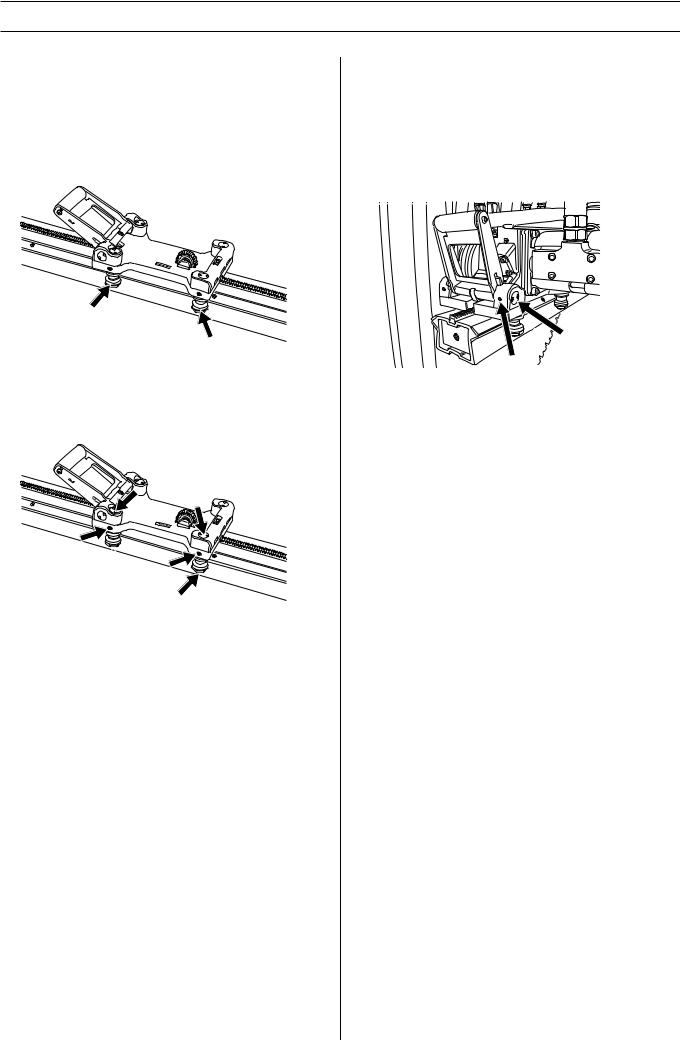
In order for the saw to run stably and saw a straight cut, the four guide wheels must rest against the rail and not have too much play. When there is too much play between the saw carriage and rail the guide wheels must be adjusted:
The two marked guide wheels have eccentric axles and by turning these the carriage is tightened onto the rail.
Start by loosening the marked nuts (1) with the supplied special tool. Now loosen the two stop screws (2). When these are loose, adjust the guide wheels (3) against the rail by turning them towards the rail so the play is taken up. Hold the guide wheels and screw in the stop screw. Now screw on the nuts to secure the guide wheels in the new position.
1
1
2
 2 3
2 3
3
Adjust the saw carriage
As the saw wears, after a number of hours working, it can be a good idea to ensure that the saw sits firmly in the saw carriage and rail. If not, the handle probably needs adjusting:
Loosen the marked (1) socket headed screw (one on each side of the handle). Now turn the eccentric axles (2) with the help of the supplied special tool until the axle lies tight against the saw. Now tighten the socket headed screw.
2
1
14 – English
MAINTENANCE
Service
IMPORTANT! All types of repairs may only be carried out by authorised repairmen. This is so that the operators are not exposed to great risks.
After 100 hours of operation, the message "Time for servicing" is displayed. The entire equipment shall then be taken to an authorized Husqvarna dealer for servicing.
Maintenance
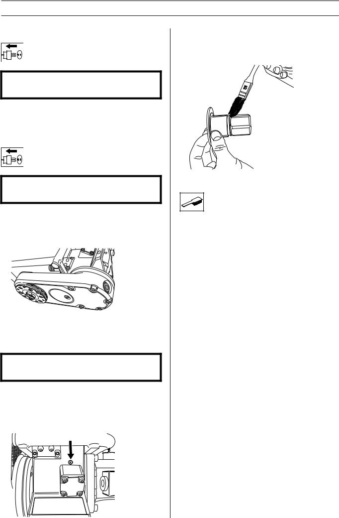
IMPORTANT! Inspection and/or maintenance should be carried out with the motor switched off and the plug disconnected.
Oil change cutting arm
There is an oil plug for draining the oil located on the cutting arm. This plug should be cleaned when changing the oil. The new oil is filled through the hole where the oil plug sits.
The cutting arm contains 1 dl of Husqvarna Oil 150, a transmission oil of the type EP 150. The oil should be replaced for the first time in connection with the first service. A 1 dl bottle of oil is supplied when the machine is new.
IMPORTANT! Used engine oil and transmission oil is hazardous to health and must not be disposed of in the ground or out of doors.
Lubrication of feeder gears
There are two grease nipples on every saw unit. Through these the gears for the feeding engines can be lubricated. Lubricate daily or at least every 30 hours of operation. Use VEIDEC POWER LUBE or corresponding grease.
Grease the blade spindle
In order for the blade spindle to be fitted as easily as possible, it may be necessary to grease the hexagonal blade spindle. At the same time check that the hexagon is not damaged.
Daily maintenance
1Check that all couplings, connections and hydraulic hoses are in full working order.
2Clean the outside of the machine. Do not use a high pressure washer to clean the saw.
3Check that the blade and th blade guard is not damaged or cracked. Replace the blade or the blade guard if it is exposed to impact or is cracked.
English – 15
|
TECHNICAL DATA |
WS 463 |
|
Weight |
|
Saw carriage, kg/lbs |
3,7/8,15 |
Saw unit, kg/lbs |
22/48,5 |
Blade guard kg/lbs |
15/33 |
Track 1200 mm (47”) kg/lbs |
12,2/26,9 |
Track 2000 mm (79”) kg/lbs |
17,2/37,9 |
Hydraulic fluid flow, max, l/m / gpm |
65/17 |
Pressure max, bar/psi |
230/3340 |
Travel feed |
Hydraulic |
Depth feed |
Hydraulic |
The stated weight for the two rails refers to one rail with the saw carriage fitted. To find the weight of just the rail, you must deduct the weight of the saw carriage from the weight stated.
Cutting speed, m/s
Blade diameter, mm |
600 |
700 |
800 |
1000 |
1200 |
1500 |
1600 |
|
|
|
|
|
|
|
|
Spindle speed 1400 rpm pos.3 |
44 |
51 |
|
|
|
|
|
|
|
|
|
|
|
|
|
Spindle speed 1000 rpm pos.2 |
|
|
42 |
52 |
|
|
|
|
|
|
|
|
|
|
|
Spindle speed 630 rpm pos.1 |
|
|
|
|
40 |
49 |
53 |
|
|
|
|
|
|
|
|
Cutting speed, ft/min
Blade diameter, inches |
24 |
28 |
32 |
40 |
47 |
59 63 |
Spindle speed 1400 rpm pos.3 |
8797 |
10263 |
|
|
|
|
Spindle speed 1000 rpm pos.2 |
|
|
8378 |
10472 |
|
|
Spindle speed 630 rpm pos.1 |
|
|
|
|
7752 |
9731 10391 |
Cutting capacity
Blade diameter, |
Cutting capacity |
mm/inches |
mm/inches |
800/32 |
330/13 |
1000/40 |
430/17 |
1200/48 |
530/21 |
1600/63 |
730/29 |
Never use blades other than original blades designed for the machine.
16 – English

TECHNICAL DATA
EC-declaration of conformity
Husqvarna Construction Products Sweden AB, Box 2098, 550 02 Jönköping, Sweden, tel: 036-570 60 00, hereby declares that its WS 463 wall saw, from serial number 01001 onwards, is manufactured in compliance with the Council’s machinery directive 98/ 37/EC, low-voltage directive 73/23/EEC and EMC directive 89/336/EEC, including subsequent amendments, and that the following standards have been used for guidance: EN 55 014-1, EN 55 014-2, EN 61 000-3-2, EN 50 144-1, EN 13 862.
The supplied wall saw conforms to the example that underwent EC type examination.
Jönköping 2005-01-01
Christer Carlberg
Managing Director
English – 17
ACLARACIÓN DE LOS SÍMBOLOS
Símbolos en la máquina:
¡ATENCIÓN! La máquina, si se utiliza de forma errónea o descuidada, puede ser una herramienta peligrosa que puede causar daños graves e incluso la muerte al usuario y a otras personas.
Lea detenidamente el manual de instrucciones y asegúrese de entender su contenido antes de utilizar la máquina.
Utilice siempre:
•Casco protector homologado
•Protectores auriculares homologados
•Gafas protectoras o visor
•Máscara respiratoria
Este producto cumple con la directiva CE vigente.
Símbolos en el manual de instrucciones:
El control y/o mantenimiento de la máquina debe hacerse con el motor parado y el enchufe desenchufado.
Utilice siempre guantes protectores homologados.
La máquina debe limpiarse regularmente.
Control visual.
Debe utilizarse gafas protectoras o visor.
18 – Spanish

ÍNDICE
Índice |
|
ACLARACIÓN DE LOS SÍMBOLOS |
|
Símbolos en la máquina: ............................................. |
18 |
Símbolos en el manual de instrucciones: .................... |
18 |
ÍNDICE |
|
Índice ........................................................................... |
19 |
¿QUÉ ES QUÉ? |
|
¿Componentes de la sierra de pared? ........................ |
20 |
INSTRUCCIONES DE SEGURIDAD |
|
Pasos necesarios antes de utilizar una sierra de pared |
|
nueva ........................................................................... |
21 |
Equipo de protección personal .................................... |
21 |
Instrucciones generales de seguridad ......................... |
22 |
Instrucciones generales de trabajo .............................. |
22 |
Técnica básica de trabajo ............................................ |
23 |
PRESENTACIÓN |
|
WS 463 ........................................................................ |
24 |
MONTAJE |
|
Riel y accesorios del soporte de pared ....................... |
25 |
Instalación del carro y de la sierra ............................... |
26 |
Monte el disco .............................................................. |
26 |
Corte liso ...................................................................... |
27 |
Monte la protección del disco ...................................... |
28 |
Conecte la unidad hidráulica ....................................... |
28 |
ARRANQUE Y PARADA |
|
Antes de arrancar ........................................................ |
29 |
Arranque ...................................................................... |
29 |
Parada ......................................................................... |
29 |
Desmontaje de la sierra ............................................... |
29 |
Limpieza ...................................................................... |
29 |
REGLAJES Y AJUSTES |
|
Ajuste de las ruedas de guía ....................................... |
30 |
Ajuste la sierra en el carro ........................................... |
30 |
MANTENIMIENTO |
|
Servicio ........................................................................ |
31 |
Mantenimiento ............................................................. |
31 |
Mantenimiento diario ................................................... |
31 |
DATOS TECNICOS |
|
WS 463 ........................................................................ |
32 |
Declaración CE de conformidad .................................. |
33 |
Spanish – 19

|
|
¿QUÉ ES QUÉ? |
|
|
2 |
|
10 |
6 |
9 |
|
|
|
||
|
|
|
|
|
|
7 |
|
|
|
1 |
|
|
|
|
|
4 |
|
|
8 |
|
|
|
|
|
|
3 |
|
5 |
11 |
|
|
|
¿Componentes de la sierra de pared?
1 |
Carro de la sierra |
7 |
Riel |
2 |
Empuñadura de bloqueo |
8 |
El cubo de brida de disco |
3 |
Unidad de sierra |
9 |
Brida exterior de acoplamiento de discos |
4 |
Válvula de velocidad |
10 |
Conexiones de las mangueras hidráulicas |
5 |
Brazo de corte |
11 |
Conexión de agua |
6 |
Guía de la protección del disco |
|
|
20 – Spanish
INSTRUCCIONES DE SEGURIDAD
Pasos necesarios antes de utilizar una sierra de pared nueva
•Lea detenidamente el manual de instrucciones y asegúrese de entender su contenido antes de utilizar la máquina.
•Esta máquina está diseñada y prevista para serrar hormigón, ladrillos y distintos tipos de piedra. Cualquier otro uso se considerará inadecuado.
•Esta máquina sólo está destinada a ser utilizada junto con Husqvarna PP 355, Husqvarna PP 455 y Husqvarna RC 455. Está prohibida cualquier otra aplicación.
•La máquina está destinada al uso por operadores experimentados, en aplicaciones industriales.
•Lea el manual de instrucciones suministrado con la unidad hidráulica antes de utilizar la máquina.
•La máquina puede ocasionar lesiones graves. Lea atentamente las instrucciones de seguridad. Aprenda a utilizar la máquina.
Emplee siempre el sentido común.
Es imposible abarcar todas las situaciones en las que puede encontrarse. Utilice siempre el equipo con cuidado y sentido común. Evite todas aquellas situaciones que considere que sobrepasan sus capacidades. Si, después de leer estas instrucciones, no está seguro del procedimiento que debe seguir, consulte a un experto antes de utilizar el equipo.
No dude en ponerse en contacto con su distribuidor si tiene preguntas acerca del uso de la máquina. Estaremos encantados de poder aconsejarle y ayudarle a utilizar la máquina de manera eficaz y segura.
Diríjase a su distribuidor de Husqvarna para que revise la máquina regularmente y para que realice ajustes y reparaciones básicas.
Toda la información y todos los datos contenidos en este manual de instrucciones son vigentes en la fecha de impresión del manual.
¡ATENCIÓN! No está permitido modificar el
!diseño original de la máquina, por ningún motivo, sin la autorización del fabricante. Utilice siempre accesorios originales. Las modificaciones y/o el uso de accesorios no autorizados comportan riesgo de daöos personales graves y peligro de muerte para el usuario y otras personas.
¡ATENCIÓN! El uso de productos de corte,
!amolado, taladrado, lijado o formación de materiales puede generar polvo y vapores que pueden contener productos químicos perniciosos. Averigüe la índole del material de trabajo y utilice una máscara contra polvo o respiratoria adecuada.
Equipo de protección personal
¡ATENCIÓN! Para trabajar con la máquina
!debe utilizarse un equipo de protección personal homologado. El equipo de protección personal no elimina el riesgo de lesiones, pero reduce su efecto en caso de accidente. Pida a su distribuidor que le asesore en la elección del equipo.
•Casco protector
•Protectores auriculares
•Gafas protectoras o visor
•Máscara respiratoria
•Guantes resistentes de agarre seguro.
•Prendas de vestir ceñidas, resistentes y cómodas que permitan una libertad de movimientos total.
•Botas con puntera de acero y suela antideslizante.
•Tenga siempre a mano el equipo de primeros auxilios.
Spanish – 21
Loading...