

Page 1

HUSQVARNA MOTORCYCLES S.R.L .
BMW GROUP
www.husqvarna-motorcycles.com
Part. n. 8000 H0478
WR 250 2009
WR 300 2009
WR 250 2009
WR 300 2009
LIBRETTO USO
E MANUTENZIONE
OWNER’S MANUAL
LIVRET D’UTILISATION
’ENTRETIEN
ET D
BETRIEBSANLEITUNG
MANUAL DE USO
Y MANTENIMIENTO
Page 2

HUSQVARNA MOTORCYCLES S.R.L. declina qualsiasi responsabilità per eventuali errori in
cui può essere incorsa nella compilazione del presente manuale e si riserva il diritto di apportare qualsiasi modifica richiesta dallo sviluppo evolutivo dei propri prodotti. Le illustrazioni riportate sono indicative e potrebbero non corrispondere esattamente al particolare trattato. É vietata
la riproduzione anche parziale della presente pubblicazione senza autorizzazione scritta.
1a Edizione (06-08)
To the best knowledge of HUSQVARNA MOTORCYCLES S.R.L. the material contained herein
is accurate as of the date this pubblication was approved for printing. HUSQVARNA
MOTORCYCLES S.R.L., Inc. reserves the right to change specifications, equipment, or designs
at any time without notice and without incurring obligation. Illustrations in this manual are merely
for demonstration purposes and could not exactly match the detail described.No part of this
manual can de reproduced without permission in writing of the copyright holder.
st
1
Edition (06-08)
HUSQVARNA MOTORCYCLES S.R.L. décline toute résponsabilité pour erreurs évuntuelles
commises pendant la rédaction du manuel et question et se réserve le droit d’apporter tous les
perfectionnements nécessaires sans avis préalable. Les illustrations gravées dans ce manuel
ne sont qu’à titre idicatif et pourraient ne pas correspondre au détail traité. Le copiage partiel ou
totale de ce manuel sans autorisation écrite est strictement interdit.
ére
1
édition (06-08)
HUSQVARNA MOTORCYCLES S.R.L. lehnt jegliche Verantwortung für eventuelle Fehler ab,
welche bei der Zusammenstellung dieses Handbuches entstanden sein können und behält sich
ferner das Recht vor, alles, was sich an Änderungen durch die Weiterentwicklung ihrer Produkte
ergeben sollte, in diesem Hendbuch anzuführen. Die wiedergegebenen Darstellungen sind indikativ und Könnten nicht genau dem betreffenden Teil entsprechen. Die Reproduktion, auch teilweise, der vorliegenden Harausgabe ohne vorheriger schriftlicher Genehmigung ist untersagt.
1. Auflage (06-08)
HUSQVARNA MOTORCYCLES S.R.L. no se responsabiliza por los errores debidos a la com-
pilación del presente manual y se reserva el derecho de aportar toda modificación necesaria
para el desarrollo evolutivo de sus productos. Las ilustraciones presentadas son indicativas y
pueden no corresponderse exactamente con la pieza tratada. Se prohibe la reproducción, también parciel, de la presente publicación sin autorización por escrito.
1°Ediciòn (06-08)
Page 3

Dove non diversamente specificato, i dati e le prescizioni si riferiscono a tutti i modelli.
Unless specified, data and presciption are referred to all t he models.
Lorsque non différemment indiqué, les donneé et les instructions se réfèrent à tous les modèles.
Wo nicht anders ausdrücklich angegeben, beziehen sich die Daten und die Vorschriften auf alle Modelle.
Donde no especificado, los datos y resenas se refieren a todos los modelos.
WR 250 2009
WR 300 2009
CARATTERISTICHE - USO - MANUTENZIONE
SPECIFICATIONS - OPERATION - MAINTENANCE
CARACTERISTIQUES - UTILISATION - ENTRETIEN
MERKMALE - GEBRAUCH - WARTUNG
CARACTERISTICAS - USO - MANTENIMIENTO
3
Page 4

PRESENTAZIONE
Benvenuti nella famiglia motociclistica
Husqvarna!
La Vostra nuova motocicletta Husqvarna é stata
progettata e costruita per essere la migliore
della sua categoria. Le istruzioni di questo
manuale sono state preparate per fornire una
guida semplice e chiara alla manutenzione del
motociclo. Per ottenere da esso le migliori
prestazioni, si raccomanda di seguire
attentamente quanto riportato su questo
manuale. In esso sono racchiuse le istruzioni
per effettuare le necessarie operazioni di
manutenzione. Le riparazioni o le manutenzioni
più specifiche o di maggiore entità richiedono il
lavoro di meccanici esperti e l’uso di apposite
attrezzature. Il Vostro Concessionario
Husqvarna ha i ricambi originali, l’esperienza e
tutte le attrezzature necessarie per renderVi un
ottimo servizio.
Ricordare infine che il “Manuale di uso
e manutenzione” ed il “Libretto di
registrazione vendita” devono considerarsi
parti integranti del motociclo e come tali
rimanere allegati allo stesso anche in
caso di rivendita.
Questo motociclo utilizza componenti progettati
e realizzati grazie a sistemi e tecnologie
d’avanguardia e sperimentati nelle competizioni.
Nelle motociclette da competizione ogni
particolare é verificato dopo ogni gara al fine di
garantire sempre le migliori prestazioni.
Per il corretto funzionamento del motociclo é
necessario attenersi alla tabella di controllo e
manutenzione riportata a pag. 208.
PRESENTATION
Welcome to the Husqvarna motorcycling
Family!
Your new Husqvarna motorcycle is designed
and manufactured to be the finest in its field.
The instructions in this book have been
prepared to provide a simple and
understandable guide for your motorcycle’s
operation and care.
Follow the instructions carefully to obtain
maximum performance and your personal
motorcycling pleasure. Your owner’s manual
contains instructions for owner care and
maintenance. The main work of repair or
maintenance requires the attention of a skilled
mechanic and the use of special tools and
equipment.
Your Husqvarna dealer has the facilities,
experience and original parts necessary to
properly render this valuable service.
This “Owner’s Manual” and the
“Purchase Registration Booklet” are parts
and parcels of the motorcycle, hence, they
have to remain with the motorcycle even
when sold to another user.
This motorcycle uses components designed
thanks to systems and state of the art
technologies which are thereafter tested in
competition.
In competition motorcycles, every detail is
verified after each race in order to always
guarantee better performance. For correct
functioning of the vehicle, it is necessary to
follow the maintenance and control table found
on page 208.
PRESENTATION
Bienvenus dans la famille motocycliste
Husqvarna! Votre nouvelle moto Husqvarna a été
projetée et construite pour qu’elle soit la
meilleure dans son genre. Les instructions de
service ci-incluses ont été préparées pour vous
fournir une guide d’entretien et de
fonctionnement simple et clair.
Afin d’obtenir les meilleures performances de
votre moto, veuillez suivre attentivement les
instructions ici contenues, qui sont les plus
simples à suivre pour les opérations d’entretien.
Les réparations ou les entretiens plus spécifiques
ou plus importants requièrent l'intervention de
mécaniciens experts et l'utilisation d'équipements
spécifiques Votre Concessionnaire Husqvarna
en sus des pièces de rechange originales, a
l’expérience et tous les outils nécessaires à vous
rendre un service excellent.
Rappeler en outre que le “Livret d'utilisation
et de entretien” et le “Carnet Rapport de
Vente” font partie intégrantes du motocycle et
donc rester joints aussi au même en cas de
revente.
Cette motocyclette utilise des éléments projetés
et realizés grace à systèmes et technologies
d’avanguard et expérimentés dans les
competitions.
Dans les motocyclette de competition, chaque
détail est vérifié après toutes les races pour
garantir les meilleur performances. Pour le
correct fonctionnement de la motocyclette, c’est
nécessaire suivre le tableau de control et
maintien à la page 208.
4
Page 5

EINFÜHRUNG
Ein Willkommen in der Familie der Motorradfahrer
Husqvarna! Ihr neues Motorrad Husqvarna ist so
entworfen und hergestellt worden, um das beste in
seiner Klasse darzustellen. Die Anweisungen in
diesem Handbuch sind vorbereitet worden, um
Ihnen eine einfache und klare Anleitung für die
Wartung des Motorrades zu geben.
Wenn Sie den Anweisungen dieses Handbuches
genau folgen, werden Sie die besten Leistungen
mit dem Motorrad erzielen. In diesem Handbuch
finden Sie die Instruktionen für die notwendigen
Arbeitsgänge für die Wartung. Anweisungen für
Reparaturen und Wartungen besonderer Natur
oder grösserer Ausmasse sind in dem
Reparaturhandbuch Husqvarna enthalten.
Spezielle Reparaturen oder Wartungen größeren
Ausmaßes, benötigen den Einsatz von
Facharbeitern sowie entsprechende Ausrüstungen.
Ihr Vertragshändler Husqvarna hat die OriginalErsatzteile, die Erfahrung und alle notwendigen
Ausrüstungen, um Sie bestens zu bedienen.
Schließlich erinnern, daß der Betrebsanleitung"
und die " Kauf- Anmeldung Heft" muß
integrierende Geburten des Motorrades
betrachtet werden und deshalb müssen sie
immer das Fahrzeug begleiten, bei auch
Verkauf.
Dieses Motorrad montiert bildend das sie
gezeichnet wurden und es verwirklicht wurden
danke zu Systemen und Technologien von
Avantgarde und daß sie in den Wettkämpfen
versucht wurden.
Um immer die besten Leistungen garantieren zu
können, in dieser Typ von Motorrädern jedes
besondere es wird nach jedem Wettkampf
kontrolliert. Für das korrekte Funktionieren des
Motorrades ist er notwendig den Hinweisen, die auf
der Tabelle von Kontrolle und Wartung (zu Seite
209 sehen) sind, zu folgen.
PRESENTACION
Bienvenidos a la familia motociclista Husqvarna! Su
nueva motocicleta Husqvarna ha sido proyectada y
fabricada para destacar en su categoría. Las
instrucciones de este manual han sido preparadas
para brindar una guía sencilla y clara para el
mantenimiento de la motocicleta Para obtener de la
misma las mejores prestaciones, se recomienda
seguir atentamente todo lo que se explica en este
manual.
Aquí se encuentran las instrucciones para efectuar
las operaciones necesarias de mantenimiento.
Su Concesionario Husqvarna tiene los recambios
originales, la experiencia y todas las herramientas
necesarias para brindarle el mejor servicio.
Recordar por fin que el "Manual de uso y
mantenimiento" y el "Manual de registro de
venta" tienen que considerarse partos
integrantes del motociclo y como tales también
quedar alegados al mismo en caso de reventa.
Esta motocicleta utiliza particular dibujados y
realizados gracias a sistemas y a tecnologías de
punta y experimentados en las competiciones.
En las motocicletas de competición cada detalle es
averiguado después de cada competición para
siempre garantizar las mejores prestaciones.
Por el correcto funcionamiento del motociclo, es
necesario atenerse al tablero de control y
manutención indicado a pág.
209).
5
Page 6

AVVERTENZE IMPORTANTI
IMPORTANT NOTICES
AVIS IMPORTANT
I modelli WR sono motocicli per impiego
STRADALE (A POTENZA LIMITATA), garantiti
esenti da difetti e coperti da garanzia legale, a
condizione che VENGA MANTENUTA LA
CONFIGURAZIONE DI SERIE e rispettata la
tabella di manutenzione riportata a pag.218.
Qualora i modelli WR venissero trasformati in
motocicli DA COMPETIZIONE (A PIENA
POTENZA), la tabella di manutenzione consigliata
per uso agonistico è riportata a pagina 208.
IMPORTANTE
Per il riconoscimento della garanzia farà da
riferimento la CONFIGURAZIONE DEL VEICOLO,
come descritto di seguito:
A) - MOTOCICLO DI SERIE, PER USO
STRADALE: A POTENZA LIMITATA
B) - MOTOCICLO DA COMPETIZIONE, PER USO
AGONISTICO: A PIENA POTENZA
6
WR are STREET LEGAL motorcycles (with
LIMITED POWER ENGINE); they are guaranteed
exempt from functional defects and covered with
legal guarantee, if the STANDARD
CONFIGURATION is maintained and the
suggested maintenance table, shown on page
218, is observed.
If WR are transformed in COMPETITION
MOTORCYCLES (with FULL POWER ENGINE),
the suggested maintenance table for competition
use is shown on page 208.
IMPORTANT
The reference for recognition of the guarantee
will be the MOTORCYCLE CONFIGURATION, as
shown below:
A) - STANDARD MOTORCYCLE, STREET
LEGAL: with LIMITED POWER ENGINE
B) - COMPETITION MOTORCYCLE, RACING
USE: with FULL POWER ENGINE
Les modèles WR êtes motocycles pour emploi
ROUTIER (AVEC LA PUISSANCE LIMITÉ)
garantis exempté par défauts et couvert par
garantie juridique, à la condition que je sois
MAINTENUE LA CONFIGURATION DE SÉRIE et
respectée le tableau d’entretien reporté au page
218.
Si les modèles WR ils vinssent transformés en
motocycles DE COMPÉTITION (AVEC LA PLEINE
PUISSANCE), le tableau d’entretien
conseillé pour usage sportif est reporté à page 208.
IMPORTANT
Pour la reconnaissance de la garantie il fera à la
référence la CONFIGURATION DU VÉHICULE,
comme de suite décrit:
A) - MOTOCYCLE DE SÉRIE, POUR USAGE
ROUTIER: AVEC LA PUISSANCE LIMITÉ
B) - MOTOCYCLE DE COMPÉTITION, POUR
USAGE SPORTIF: AVEC LA PLEINE
PUISSANCE
Page 7

WICHTIGE ANWEISUNGEN
ADVERTENCIAS IMPORTANTES
WR sind STRAßE GESETZLICHE
Motorräder (mit beschränktem MACHT-MOTOR); sie
werden garantiert, befreien Sie von zweckmäßigen
Defekten und deckte mit gesetzlicher Garantie, wenn
die ÜBLICHE KONFIGURATION und der
vorgeschlagene Aufrechterhaltungstisch beibehalten
wird, gezeigt auf Seite 219, wird beobachtet.
Wenn WR in KONKURRENZ-MOTORRÄDER
umgewandelt werden (mit VOLLEM MACHTMOTOR), wird der vorgeschlagene
Aufrechterhaltungstisch für die
Konkurrenzverwendung auf Seite 209, gezeigt.
WICHTIG
Der Hinweis für Anerkennung der Garantie wird die
MOTORRAD-KONFIGURATION sein, wie unten
gezeigt:
A) ÜBLICHES MOTORRAD, STRAßE
GESETZLICH: mit beschränktem MACHT-MOTOR
B) WETTBEWERB MOTORRAD, das Machen
EINEN WETTKAMPF MIT von der VERWENDUNG:
mit VOLLEM MACHT-MOTOR.
Los modelos WR son motociclos por empleo VIAL
(A POTENCIA LIMITADA), garantizados eximidos
por defectos y cubiertos de
garantía legal, a condición que sea MANTENIDA
LA CONFIGURACIÓN DE SERIE y respetada el
tablero de manutención indicada a pág 219.
En caso de que los modelos WR fueran
transformados en motociclos POR COMPETICIÓN
(A LLENA POTENCIA) el tablero de manutención
aconsejado para empleo agonístico es
reconducido a las páginas 283 y 209.
IMPORTANTE
Por el reconocimiento de la garantía hará de
referencia la CONFIGURACIÓN DEL VEHÍCULO,
como descrito en seguida:
A) - MOTOCICLO DE SERIE, PARA USO VIAL: A
POTENCIA LIMITADA
B) - MOTOCICLO DE COMPETICIÓN, PARA USO
AGONÍSTICO: A LLENA POTENCIA
7
Page 8

Questo motociclo non é stato studiato per
percorrere lunghi tragitti con il motore sempre
al massimo dei giri come può avvenire in
occasione di lunghi trasferimenti stradali o
autostradali. Lunghi tragitti a pieno gas
possono comportare gravi danni al motore.
Questo motociclo non é stato progettato per
uso urbano e non é dotato di elettroventola e
termostato. Lunghe soste al semaforo con il
motore acceso possono causare un
surriscaldamento di quest’ultimo con
l’ebollizione dell’acqua del radiatore.
Questo motociclo presenta un assetto studiato
per le competizioni e quindi garantisce il
massimo delle prestazioni con il solo pilota .
Se ne sconsiglia pertanto l’uso, in fuoristrada o
in pista, con il passeggero.
This motorcycles was not designed for long
trips with the engine always at maximum rpm
as can occur whilst travelling on roads or
highways. Long trips at full throttle can cause
severe damage to the engine.
This motorcycles was not designed for urban
use and is not equiped with a cooling fan and
thermostat. Long stops at the traffic lights
can cause overheating and the boiling of
radiator water.
This motorcycles is setup for competition use
and therefore guarantees maximum
performance with the rider alone. It is thereby
not recommended to use the vehicle on
circuits or off-road with a passenger.
Cette motocyclette n’était pas projeté pour
parcourir longs trajets avec le moteur toujours
au maximum des tours comme peut se passer
en occasion des longs trajets sur routes ou
autoroutes. Longs trajets au plein gaz peuvent
causer des dégats au moteur.
Cette motocyclette n’était pas projeté pour
l’emploi urbain et n’est pas fourni de électroventilateur et thermostat. Longs
stationnements au sémaphore avec le moteur
brulant peuvent provoquer un surchauffage du
moteur avec l’ébullition de l’eau dans le
radiateur.
Cette motocyclette présent un setup pour les
competitions et donc le maximum des
performances sont garantis avec seulement
un pilote. L’utilisation dans les circuits ou tout
terrain avec un passager n’est pas conseillé.
8
Page 9

Dieses Motorrad wurde nicht ausgedacht, um immer
höchstens einige Drehungen lange Reisen mit dem
Motor vorzunehmen, wie es anläßlich langer
Verschiebungen auf Straßen oder Autobahnen
geschehen kann. Die langen Reisen in diese
Bedingungen können zum ernste Schäden
verursachen Motor.
Dieses Motorrad wurde nicht für einen städtischen
Gebrauch gelernt und also ist es unversorgt von
Elektrobelüfter und Thermostat. Lange Haltestellen
zur Verkehrsampel mit dem entzündeten Motor
sie können eine Überheizung von dieses letzten
verursachen, sie verursachen hier deshalb Wasser in
den Heizkörpern kochen.
Dieses Motorrad wurde für die Wettkämpfe und den
Abschluß gelernt es garantiert die besten Leistungen
mit dem einzigen Fahrer. Sie rät ab deshalb sie mit
dem Passagier benutzen, sowohl auf Straße, daß ins
geländegängige.
Este motociclo no ha sido estudiado para
recorrer largos trayectos con el motor
a lo sumo de las vueltas como puede ocurrir
con ocasión de largos traslados viales o
de autopista. Largos trayectos a lleno gas
pueden comportar graves daños al
motor.
Este motociclo no ha sido planeado por un
empleo urbano y no es dotado de
electroventilador y termostato. Largas paradas
al semáforo con el motor encendido
pueden causar un sobrecalentamiento de este
último con la ebullición del agua
en el radiador.
Este motociclo ha sido estudiado por las
competiciones y por lo tanto
sólo garantiza lo máximo de las prestaciones
con el piloto. Desaconseja por tanto
el empleo, en todoterreno o en pista, con el
pasajero.
9
Page 10

Per mantenere la “Garanzia di Funzionamento”
del veicolo, il Cliente deve seguire il
programma di manutenzione indicato sul
libretto di uso e manutenzione eseguendo i
tagliandi presso le officine autorizzate
HUSQVARNA. Il costo per la sostituzione dei
pezzi e per la manodopera necessaria per
rispettare il piano di manutenzione, è a carico
del Cliente.
NOTA: la garanzia DECADE in caso di noleggio
del motociclo
In order to maintain the vehicle’s “Guarantee
of Functionality”, the client must follow the
maintenance program indicated in the user’s
manual by carrying out maintenance checks
at authorized HUSQVARNA dealers. The cost
for substituting parts and for the labour
necessary in order to respect the
maintenance plan, is charged to the client.
NOTE: the guarantee is EXTINGUISHED in the
case where the motorcycle is rented.
Pour maintenir la "Garantie de
Fonctionnement" du véhicule, le Client doit
suivre le programme d'entretien indiqué sur
le livret d'usage et entretien en exécutant les
coupons près des ateliers autorisés
HUSQVARNA. Le coût pour la substitution
des bouts et pour la main-d'oeuvre
nécessaire pour respecter l'étage d'entretien
est à la charge du Client.
NOTE: la garantie DÉCHOIT en cas de
location du motocycle.
Le indicazioni di destra e sinistra si riferiscono ai
due lati del motociclo rispetto al senso di marcia.
Z: n° denti
A: Austria
AUS: Australia
B: Belgio
BR: Brasile
CDN: Canada
CH: Svizzera
D: Germania
E: Spagna
F: Francia
FIN: Finlandia
GB: Gran Bretagna
I: Italia
J: Giappone
USA: Stati Uniti d’America
Dove non diversamente specificato, i dati e le
prescrizioni si riferiscono a tutte le Nazioni.
Note
10
References to the “left” or “right” of the
motorcycle are in the sense of a person facing
forwards.
Note
Z: number of teeth
A: Austria
AUS: Australia
B: Belgium
BR: Brazil
CDN: Canada
CH: Switzerland
D: Germany
E: Spain
F: France
FIN: Finland
GB: Great Britain
I: Italy
J: Japan
USA: United States of America
Where not specified, alla the data and the
instructions are referred to any and all
Countries.
Les indications “droite” et “gauche” se refèrent
aux deux côtés du motocycle par rapport au
sens de marche.
Z: numéro dents
A: Autriche
AUS: Australie
B: Belgique
BR: Brasile
CDN: Canada
CH: Suisse
D: Allemagne
E: Espagne
F: France
FIN: Finlande
GB: Grand Bretagne
I: Italie
J: Japon
USA: Etas Units d’Amerique
Si non différemment spécifié, les données et
les instructions sont valables pour tous les
Pays.
Avis
Page 11

Um die "Garantie von Funktionieren" des
Fahrzeuges zu erhalten, muß der Kunde dem
Programm von Wartung folgen das auf ihn auf
dem Libretto von Gebrauch und Wartung
gezeigt wird, da führt es die bei den
Werkstätten genehmigt HUSQVARNA
vorgesehenen Abschnitte aus. Der Preis für
den Ersatz der Stücke und um den Plan von
Wartung zu beachten, ist er zu Lasten der
Kunde für die notwendige Arbeitskräfte.
ZUR BEACHTUNG: die Garantie verfällt bei
Vermietung des Kraftrades.
Para mantener la "Garantía de
Funcionamiento" del vehículo, el Cliente tiene
que seguir el programa de manutención
indicado sobre el manual de uso y
mantenimiento ejecutando los cupones cerca
de los talleres lícitos HUSQVARNA. El coste
por la sustitución de los particulares y por la
mano de obra necesaria para respetar el plan
de manutención, está a cargo del Cliente.
NOTA: la garantía DECAE en caso de alquiler
del motociclo.
Die Angaben, rechts und links, beziehen sich auf
die beiden Motorradseiten in Bezug auf die
Fahrtrichtung
Note
Z: Zähne nummer
A: Österreich
AUS: Australien
B: Belgien
BR: Brasilien
CDN: Kanada
CH: Schweize
D: Deutschland
E: Spanien
F: Frankreich
FIN: Finnland
GB: Groos Britan
I: Italien
J: Japan
USA: Vereinigte Staten von
Amerika
Wenn nicht anders angegeben, beziehen sich
die Daten und Vorschriften auf alle Länder.
Las indicaciones de la derecha y la izquierda
Nota
hacen referencia a los dos lados de la moto con
respecto al sentido de marcha.
Z: nùmero dientes
A: Austria
AUS: Australia
B: Bélgica
BR: Brasil
CDN: Canadà
CH: Suiza
D: Alemania
E: España
F: Francia
FIN: Finlandia
GB: Gran Bretaña
I: Italia
J: Japòn
USA: Estados Unidos
A falta de indicaciones específicas, los datos y
las instrucciones se refieren a todos los Países.
11
Page 12

SOMMARIO Pag.
TABLE OF CONTENTS Page
RESUME Page
PRESENTAZIONE........................................4
AVVERTENZE IMPORTANTI .......................6
DATI PER L'IDENTIFICAZIONE.................12
DATI TECNICI ...........................................24
TABELLA DI LUBRIFICAZIONE,
RIFORNIMENTI..........................................36
COMANDI ..................................................38
ISTRUZIONI PER L’USO
DEL MOTOCICLO......................................68
IMPIANTO ACCENSIONE/
IMPIANTO ELETTRICO ..........................174
DOTAZIONE-PARTI OPTIONAL .............188
APPENDICE.............................................190
NOTE PER MODELLI USA/CDN-AUS 198-202
MANUTENZIONE PERIODICA/
REGOLAZIONI ........................................208
INDICE ALFABETICO ..............................228
DATI PER L'IDENTIFICAZIONE
Il numero di identificazione del motore è
stampigliato sulla parte superiore del carter
motore, mentre il numero di matricola del
motociclo è stampigliato sul tubo di sterzo del
telaio (vedere a pag 18).
Riferite sempre, annotandolo anche sul
presente libretto, il numero stampigliato sul
telaio quando ordinate i ricambi o chiedete
informazioni sul vostro motociclo.
PRESENTATION .........................................4
IMPORTANT NOTICES ...............................6
IDENTIFICATION DATA.............................12
TECHNICAL DATA ....................................24
LUBRICATION TABLE, SUPPLIES............36
CONTROLS ..............................................38
RIDING ......................................................68
IGNITION SYSTEM/
ELECTRICAL SYSTEM ..........................174
EQUIPMENT-OPTIONAL PARTS LIST ...188
APPENDIX ...............................................190
NOTE FOR USA/CDN-AUS MODELS....
198-202
PERIODIC MAINTENANCE/
ADJUSTMENT .........................................208
ALPHABETICAL INDEX .........................228
IDENTIFICATION DATA
The engine number is printed on the upper
side of the engine case, whereas the frame
number is printed on the steering tube.(see on
page 18).
Always state the number stamped on the
frame (and write it on this booklet), when
placing orders for spare parts, or when
asking for information on your motorcycle.
PRESENTATION..........................................4
AVIS IMPORTANT........................................6
ELEMENTS D'IDENTIFICATION................12
DONNEES TECHNIQUES .........................24
TABLEAU DE GRAISSAGE,
RAVITAILLEMENTS...................................36
COMMANDES ...........................................38
MODE D'EMPLOI
DE LA MOTO .............................................68
SYSTEME D'ALLUMAGE/
SYSTEME ELECTRIQUE .......................174
EQUIPEMENT-ELEMENTS EN OPTION.188
APPENDICE.............................................190
NOTE POUR LES MODELES USA/CDN-AUS
ENTRETIEN PERIODIQUE/
REGLAGES..............................................208
INDEX ALPHABETIQUE ..........................228
ELEMENTS D'IDENTIFICATION
Le numéro d'identification moteur est gravé sur
la partie supérieure du carter moteur, tandis
que le numéro de matricule de la moto est
gravé sur le tube de direction du cadre (voir
page 18).
Veuillez noter sur ce livret le numéro gravé
sur le cadre, auquel on doit toujours se référer
lors d’une commande de pièces de rechange,
ou lors d’une demande d’informations sur votre
motocycle.
..198-202
12
NUMERO TELAIO FRAME NUMBER NUMÉRO DE CADRE
Page 13
INHALTSANGABE Seite
SUMARIO Pág.
EINFÜHRUNG ............................................5
WICHTIGE ANWEISUNGEN.......................7
DATEN ZUR IDENTIFIZIERUNG...............13
TECHNISCHE DATEN...............................25
SCHMIERUNGSTABELLE, TANKEN........37
STEUERUNGEN .......................................38
DASS MOTORRAD....................................69
ZÜNDUNGSANLAGE/
ELEKTRISCHEANLAGE..........................175
AUSRÜSTUNG, EXTRA-TEILE...............189
AHNHAG..................................................191
DATEN FUR USA/CDN-AUS MODELLEN
198-202
WARTUNGSPALAN/
EINSTELLUNGEN ..................................209
ALPHABETISCHES VERZEICHNIS........229
DATEN ZUR IDENTIFIZIERUNG
Die Identifizierungsnummer des Motors ist auf
den oberen Teil des Motorcarters gestempelt,
während die Kennummerdes Motorrads auf
das Lenkrohr des Rahmens gestempelt ist
(Sie Seite 18). Bei Bestellung von Ersatzteilen
oder Anfragen über Ihr Motorrad ist immer die
auf den Rahmen gedruckte Nummer
anzugeben. Diese Nummer ist ebenfalls in die
vorliegenden Betriebsanleitungen einzutragen.
PRESENTACION ........................................5
ADVERTENCIAS IMPORTANTES...............7
DATOS PARA LA IDENTIFICACION..........13
FICHA TECNICA ......................................25
TABLA DE LUBRICACION, RELLONES....37
CONTROLES ............................................39
INSTRUCCIONES PARA EL USO
DE LA MOTOCICLETA...............................69
INSTALACION ENCENDIDO/
INSTALACION ELECTRICA ...................175
EQUIPAMIENTO-PARTES OPCIONALES..189
APENDICE ...............................................191
NOTAS POR LOS MODELOS USA/CDN-AUS
MANTENIMIENTO PERIODICO/
REGULACIONES .....................................209
INDICE ALFABETICO ..............................229
DATOS PARA LA IDENTIFICACION
El número de identificación del motor se encuentra
marcado en la parte superior del carter del motor,
mientras que el número de matrícula de la
motocicleta se encuentra marcado en el tubo de
dirección del bastidor (véaser pag.19).
piden piezas de recambio o informaciones acerca
de su motociclo, indicar siempre, apuntándolo
incluso en la presente documentación, el número
estampillado en el bastidor.
198-202
Cuando
RAHMEN NUMMER NUMERO DEL BASTIDOR
13
Page 14

Leggere attentamente il presente manuale
Premessa importante
prestando particolare attenzione alle note
precedute dalle seguenti avvertenze:
ATTENZIONE*: Indica la possibilità di subire
gravi lesioni personali fino al rischio di
decesso in caso di inosservanza delle
istruzioni.
AVVERTENZA*: Indica la possibilità di subire
lesioni personali o provocare danni al
veicolo in caso di inosservanza delle
istruzioni.
Nota*: Fornisce ulteriori utili informazioni.
Read this manual carefully and pay special
Important Notice
attention to statements preceeded by the
following words:
WARNING*: Indicates a possibility of severe
personal injury or loss of life if instructions
are not followed.
CAUTION*: Indicates a possibility of personal injury or equipment damage if instructions are not followed.
Note*: Gives helpful information.
Suivre scrupuleusement les instructions
Préliminaires
données dans ce manuel en prêtant
attention aux remarques indiquées par les
mots suivants:
ATTENTION * : Indique la possibilité de
blessures graves ou mortelles si ces
instructions ne seraient pas suivies.
ATTENTION * : Indique la possibilité que de
blessures graves soient provoquées à la
personne, ou des dommages sérieux au
véhicule, si ces instructions ne seraient pas
suivies.
Note * : Fournit d’ultérieures informations.
Sostituzione dei particolari
In caso di sostituzione dei particolari, usare
unicamente particolari ORIGINALI
Husqvarna.
14
When parts replacement is required, use
Parts Replacement
only Husqvarna ORIGINAL parts.
Pour assurer un usage sans aléa,
Remplacement de détails
remplacer les plusieurs éléments avec des
éléments ORIGINAUX Husqvarna.
Page 15

Die vorliegenden Betriebsanleitungen
Wichtige Einleitung
aufmerksam durchlesen und den
Anmerkungen, denen die folgenden Hinweise
vorausgehen, besondere Beachtung schenken :
ACHTUNG *: Zeigt die Möglichkeit an, bei
Nichtbeachtung der Anweisungen schwere
persönliche Schäden bis zum Todesfall zu
erleiden.
WARNHINWEIS* : Zeigt die Möglichkeit an, bei
Nichtbeachtung der Anweisungen persönliche
Schäden zu erleiden oder Schäden am Fahrzeug
zu verursachen.
Anmerkung * : Liefert weitere nützliche
Informationen.
Leer atentamente el presente manual
Premisa importante
prestando atención particular a las notas
precedidas por las siguientes advertencias:
ATENCIÓN *: Indica la posibilidad de sufrir
graves lesiones personales, hasta el riesgo de
muerte en caso de inobservancia de las
instrucciones.
ADVERTENCIA*: Indica la posibilidad de sufrir
lesiones personales o provocar daños al vehículo
en caso de inobservancia de las instrucciones.
Nota *: Proporciona más informaciones útiles.
Im Falle des Austausches von Teilen, nur
Austausch der Teile
Original-Husqvarna-Teile mit entsprechenden
Merkmalen einschließlich Typ, Widerstand und
Material benutzen. Andernfalls könnten
Fehlfunktionen mit möglicher
Verletzungsgefahr auftreten.
Substitución de los particulares
En caso de substitución de los particulares,
utilizar sólo partes originales Husqvarna de
características equivalentes, incluido el tipo, la
resistencia y el material. En caso contrario,
podrían producirse funcionamientos
incorrectos, con posible riesgo de lesiones.
15
Page 16

ATTENZIONE*: Dopo una caduta ispezionare
attentamente il motociclo. Assicurarsi che il
comando del gas, i freni, la frizione e tutti gli altri
principali comandi e componenti non siano stati
danneggiati. Guidare un motociclo danneggiato
può provocare gravi incidenti.
ATTENZIONE*: Non avviare o operare sul
motociclo senza aver indossato un adeguato
abbigliamento protettivo. Indossare sempre
casco, stivali, guanti, occhiali protettivi ed altro
abbigliamento appropriato.
ATTENZIONE*: Non avviare o guidare il
motociclo se non si possiedono adeguate
cognizioni unitamente ad ottime condizioni
fisiche.
WARNING*: After an upset, inspect the motorcycle carefully. Make sure that the throttle, brake,
clutch and all other systems are undamaged.
Riding with a damaged motorcycle can lead to a
serious crash.
WARNING*: Never attempt to start or operate
your motorcycle unless you are wearing appropriate protective clothing. Always wear a motorcycle helmet, motorcycle boots, gloves, goggles and other appropriate protective clothing.
WARNING*: Do not attempt to start or ride this
motorcycle until you have received expert instruction and are in excellent physical condition.
ATTENTION * : Après une chute, inspecter
soigneusement le motocycle. Assurez-vous que
la poignée des gaz, les freins, l’embrayage, et
tous les autres commandes et composants, ne
soient pas endommagés, car la conduite d’un
motocycle endommagé peut provoquer des
accidents.
ATTENTION * : Ne jamais démarrer le motocycle,
ou effectuer des opérations d’entretien, sans
s’habiller convenablement. Porter le casque, les
bottes, les gants, les lunettes pour
cyclomotoristes et tout autre mise appropriée.
ATTENTION *: Ne jamais démarrer ou conduire
le motocycle sans avoir la nécessaire
expérience. Assurez-vous d’être toujours dans
de bonnes conditions physiques.
PRECAUZIONI PER I BAMBINI
ATTENZIONE
Parcheggiare il veicolo dove non
possa essere facilmente urtato o danneggiato.
Urti anche involontari possono
provocare la caduta del veicolo con
conseguente pericolo per le persone, in
modo particolare per i bambini.
Per evitare cadute accidentali del veicolo,
non parcheggiarlo mai su terreno
molle o irregolare né sull’asfalto reso
rovente dal sole.
Poiché il motore e l’impianto di scarico
possono divenire molto caldi, parcheggiare
la motocicletta in luoghi
dove i pedoni o i bambini non possano
facilmente toccarli.
16
PRECAUTIONS FOR CHILDREN
WARNING
Park the vehicle where it is unlikely to
be bumped into or damaged. Even slight
or involuntary bumps can cause the vehicle
to topple over, with subsequent risk
of serious harm to people or children.
To prevent the vehicle from tipping
over, never park it on soft or uneven
ground, nor on asphalt strongly heated
by the sun.
Engine and exhaust pipes become
very hot during riding. Always park
your motorcycle where people or children
can not easily reach these parts,
in order to avoid serious burns.
PRECAUTIONS POUR LES ENFANTS
ATTENTION
Garer le véhicule à l'abri dans un
endroit où il ne pourra pas être heurté
ou endommagé. Les coups, même
involontaires, pourraient provoquer la
chute du véhicule avec le danger conséquent
pour les personnes, en particulier
pour les enfants.
Pour éviter toute chute accidentelle du
véhicule, ne jamais le garer sur un terrain
mouillé ou irrégulier, ni sur le goudron
rendu ardent par l'effet du soleil.
Etant donné que le moteur ou le
système d'échappement peuvent
atteindre des températures très
élevées, garer la moto dans un endroit
où les piétons ou les enfants ne pourront
pas la toucher facilement.
Page 17

ACHTUNG * : Nach einem Fall das Motorrad
sorgfältig überprüfen. Sich vergewissern, daß
die Gasschaltung, die Bremsen, die Kupplung
und andere Hauptschaltungen und
Komponenten nicht beschädigt wurden. Ein
beschädigtes Motorrad zu fahren kann schwere
Unfälle verursachen.
ACHTUNG * : Das Motorrad nicht anlassen oder
an ihm arbeiten, ohne vorher geeignete
Schutzkleidung angezogen zu haben. Immer
Schutzhelm, Stiefel, Handschuhe, Schutzbrille
und andere geeignete Kleidung tragen.
ACHTUNG * : Das Motorrad nicht anlassen und
führen, wenn nicht über geeignete Anweisungen
und ausgezeichneten körperlichen Zustand
verfügt wird.
ATENCIÓN *: Tras una caída, inspeccionar con
atención el motociclo. Asegurarse de que el
mando del gas, los frenos, el embrague y todos
los otros mandos y componentes principales no
hayan sufrido daños. Conducir un motociclo
dañado puede provocar graves accidentes.
ATENCIÓN *: No poner en marcha y no trabajar
sobre el motociclo cuando no se lleven
indumentos protectores adecuados. Llevar
siempre casco, botas, gafas protectoras y otra
indumentaria adecuada.
ATENCIÓN *: No poner en marcha o conducir el
motociclo si no se tienen las adecuadas
instrucciones junto a buenas condiciones
físicas.
SICHERHEITSMASSNAHMEN FÜR KINDER
ACHTUNG
Motorrad sicher parkieren, d.h. wo keine
Stoss- oder Schadengefahren leicht
vorkommen können. Unabsichtliche Stöße
konnten auch den Absturz des Motorrads
verursachen, mit Verletzungsgefahr von
Personen und vor allem Kindern.
Um einen unabsichtlichen Absturz zu
vermeiden, den Motorrad nie auf unebenen
oder weichen Boden oder heiße
Asphalt parkieren.
Da Motor und Auspuffanlage sehr
heiß werden können, den Motorrad
sicher parkieren, uzw. wo Kinder oder
Fußgänger nicht leicht mit solchen
Teilen in Berührung kommen können.
PRECAUCIONES PARA LOS NIÑOS
ATENCION
Aparcar el vehículo donde no pueda
ser golpeado o dañado con facilidad.
Golpes, aunque sean involuntarios
pueden provocar la caída del vehículo
con consiguiente peligro para las personas,
especialmente niños.
Para evitar caídas accidentales del
vehículo, no aparcar nunca en un terreno
flojo o irregular ni tampoco sobre
asfalto caliente.
Puesto que el motor y el escape se
pueden poner muy caliente, aparcar la
motocicleta en lugares donde sea peatones
o niños no puedan tocarlos con
facilidad.
17
Page 18

NUMERO DI
IDENTIFICAZIONE DEL
MOTOCICLO
Il numero di serie composto da
17 caratteri si trova sul lato
destro del cannotto di sterzo.
VEHICLE
IDENTIFICATION
NUMBER (V.I.N.)
The full 17 digit serial, or
Vehicle Identification Number,
is stamped on the steering
head tube (R.H. side).
NUMERO
D’IDENTIFICATION DU
MOTOCYCLE
Le numéro de série se
compose de 17 caractères et
est placé du côté droit du
fourreau de direction.
KENNUMMER
DES
MOTORRADS
Die Seriennummer besteht aus
17 Zeichen und befindet sich
auf der rechten Seite der
Lenkrohrs.
18
Page 19
NÚMERO DE
IDENTIFICACIÓN DEL
MOTOCICLO
El número de serie compuesto
de 17 caracteres se halla en el
lado derecho del eje de
dirección.
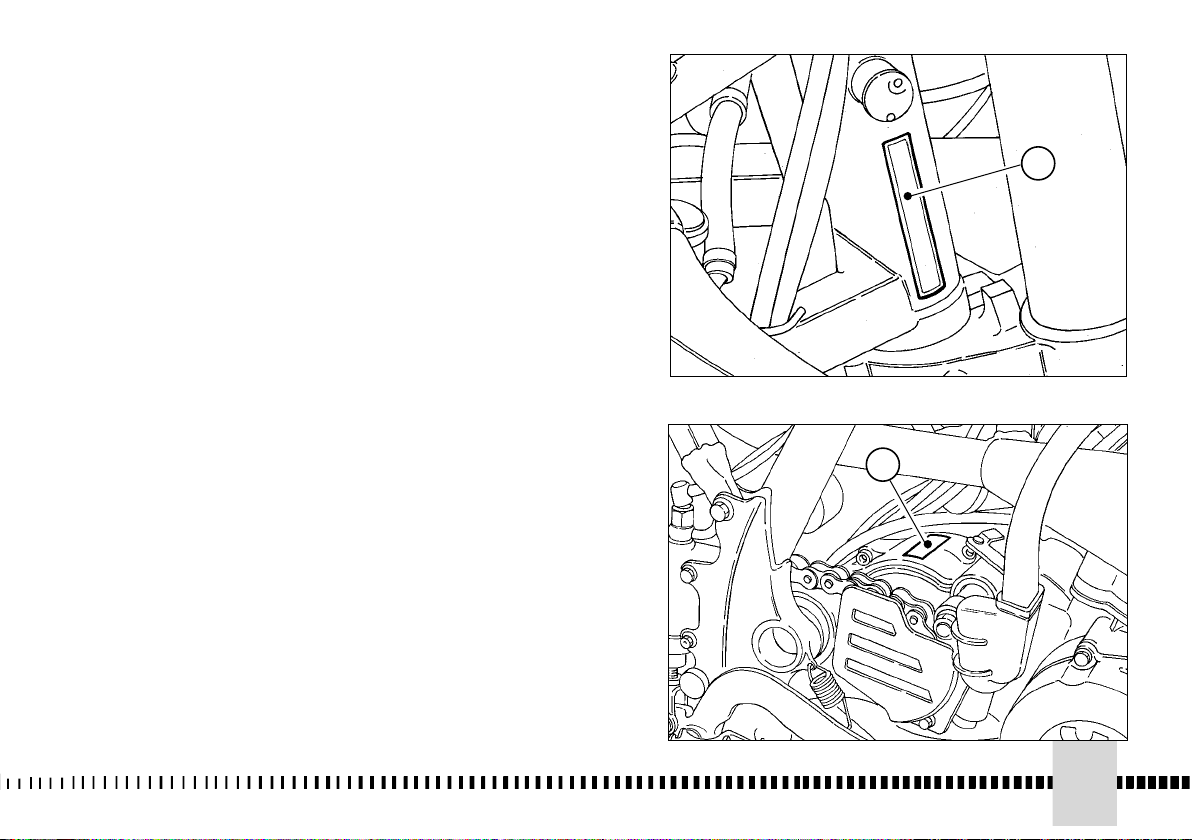
1. Matricola telaio
1. Frame serial number (V.I.N.)
1. Matricule cadre
1. Rahmen Nr.
1. Matrìcule bastidor
2. Matricola motore
2. Engine serial number
2. Matricule moteur
2. Motor Nr.
2. Matrìcule motor
1
2
19
Page 20

UBICAZIONE COMANDI
1- Leva comando freno
anteriore
2- Manopola comando gas
3- Pulsante arresto motore (lato
sinistro WR-USA/CDN; per
WR, escluso USA/CDN,
vedere a pag. 61)
4- Pedale comando freno
posteriore
5- Pedale avviamento
6- Leva comando frizione
7- Tappo serbatoio carburante
8- Pedale comando cambio. Il
cambio dispone di cinque
velocità: abbassare il pedale
per innestare la 1a marcia,
sollevarlo per innestare la
2a, la 3a, la 4a, la 5a.
CONTROL LOCATION
1- Front brake lever
2- Throttle grip
3- Engine stop button. (L.H. si-
de WR-USA/CDN; for WR,
USA/CDN excluded, see pa-
ge 61).
4- Rear brake pedal
5- Kickstarter
6- Clutch lever
7- Fuel tank filler cap
8- Gear change pedal. The
gearbox has five gears.
Depress the pedal to shift in-
to 1st gear. Raise the pedal
to shift into 2nd, 3rd, 4th, 5th.
POSITION DES COMMANDES
1- Levier de commande frein
avant
2- Poignée de gaz
3- Bouton d’arrêt moteur (côté
gauche WR-USA/CDN; pour
WR, l’exclusion des USA/CDN,
voir à la page 61).
4- Pédale de commande frein
arrière
5- Pédale de démarrage
6- Levier de commande
embrayage
7- Bouchon réservoir carburant
8 - La boîte de vitesse a cinq
vitesses. Baisser la pédale pour
embrayer la 1ère vitesse; la
soulever pour embrayer la
2ème, 3ème, 4ème, 5ème.
LAGE DER SCHALTUNGEN
1. Vorderer Bremsschalthebel
2. Gasgriff
3. Motor-Anhalt-Druckknopf
(linke Seite - WR-USA/CDN ;
für WR, ausgenommen
USA/CDN, siehe auf Seite 61)
4. Hinteres Bremspedal
5. Anlaßpedal
6. Kupplungsschalthebel
7. Treibstofftankstopfen
8- Der Gang verfügt über ünf
Geschwindigkeiten.Gang
einschalten, zum Einschalten
des 2., 3., 4., 5. Ganges das
Pedal anheben.
20
Page 21

LOCALIZACIÓN MANDOS
1 - Palanca mando freno
delantero
2 - Puño mando del gas
3 - Pulsador parada motor (lado
izquierdo - WR-USA/CDN; para
WR, excluido USA/CDN, véase
pág. 61)
4 - Pedal mando freno trasero
5 - Pedal arranque
6 - Palanca mando embrague
7 - Tapón depósito carburante
8 - Pedal mando cambio. El
cambio dispone de cinco
velocidades. apretar el pedal
para poner la 1° marcha,
soltarlo para poner la 2°, la 3°,
la 4°, la 5°.
21
Page 22

9- Dispositivo starter (lato
sinistro). Per l’avviamento a
freddo sollevare il pomello
starter
10- Rubinetto carburante. In
posizione “OFF” non c’é
passaggio di carburante dal
serbatoio al carburatore; in
posizione “ON” il
carburante passa dal
serbatoio al carburatore
11- Vite scarico aria per stelo
forcella
12- Registrazione
compressione per stelo
forcella
13- Registrazione estensione
per stelo forcella
14- Registrazione precarico
molla ammortizzatore
15- Registrazione
compressione
ammortizzatore (bassa ed
alta velocità di
ammortizzazione)
16- Registrazione estensione
ammortizzatore
9-Choke (L.H. side) When star-
ting a cold engine, raise the
choke knob
10- Fuel valve. When the fuel
valve is turned to "OFF"
fuel cannot flow from the
fuel tank to the carburetor.
When the fuel valve is turned "ON", fuel will flow the
tank to the carburetor.
11- Air release plug
12- Compression damper adju-
stment (bottom side)
13- Extension damper adjust-
ment (top side)
14- Spring preload adjustment
15- Compression damper adju-
stment (low and high dam-
ping speeds)
16- Extension damper adjust-
ment
9 - Starter (côté gauche). Pour
le démarrage à froid, soulever
la poignée du starter
10 - Robinet carburant: dans la
position “OFF”, il n’y a pas de
passage de carburant du
réservoir au carburateur; tandis
que dans la position “ON”, le
carburant passe
11- Vis de sortie d’air pour tige
fourche
12- Réglage compression pour
tige fourche
13- Réglage extension pour tige
fourche
14- Réglage précharge ressort
amortisseur
15- Réglage compression
amortisseur (basse et haute
vitesse d’amortissement)
16- Réglage extension
amortisseur
9- Starter-Einrichtung (linke
Seite). Zum Kaltanlauf den
Startergriff heben
10- Treibstoffhahn. In Position
“OFF” besteht kein Durchlauf
des Treibstoffes aus dem Tank
zum Vergaser, in Position “ON”
fließt der Treibstoff vom Tank
zum Vergaser
11. Ablaßschrauben für
Gabelschaft
12. Kompressions-Einstellung
für Gabelschaft
13. Einstellung der
Ausfederung des Gabelschafts
14. Einstellung der
Federvorladung des
Stoßdämpfers
15. Einstellung der
Kompression des Stoßdämpfers
(niedrige und hohe
Geschwindigkeit der
Dämpfung)
16. Einstellung der
Ausfederung des Stoßdämpfers
22
Page 23

9- Dispositivo starter (lado
izquierdo). Para arrancar en
frío, levantar el starter
10- Grifo del carburante. En
posición “OFF” no hay pasaje
de carburante del depósito al
carburador; en posición “ON” el
carburante pasa del depósito al
carburador
11 - Tornillo descarga aire para
vástago horquilla
12 - Ajuste compresión
para vástago horquilla
13 - Ajuste extensión
para vástago horquilla
14 - Ajuste precarga
muelle amortiguador
15 - Ajuste compresión
amortiguador (baja y alta
velocidad de amortiguación)
16 - Ajuste extensión
amortiguador
23
Page 24

MOTORE
DATI TECNICI
Tipo..........................monocilindrico a 2 tempi
Raffreddamento.................................a liquido
Alesaggio (WR 250) .........................mm 66,4
Alesaggio (WR 300) ............................mm 72
Corsa ...................................................mm 72
Cilindrata (WR 250) .......................cm3 249,3
Cilindrata (WR 300) .......................cm3 293,1
Rapporto di compressione WR 250
(a luci chiuse) .........................................8,4:1
Rapporto di compressione WR 300
(a luci chiuse) .........................................6,9:1
Avviamento ..................................... a pedale
ENGINE
TECHNICAL DATA
Type...........................2-stroke single cylinder
Cooling..............................................by liquid
Bore (WR 250)....................................2.61 in.
Bore (WR 300)....................................2.83 in.
Stroke ................................................ 2.83 in.
Capacity (WR 250).......................15.21 cu.in.
Capacity (WR 300).......................17.87 cu.in.
Compression ratio WR 250
(with closed ports)..................................8,4:1
Compression ratio WR 300
(with closed ports)..................................6,9:1
Starting ........................................kick starter
MOTEUR
DONNEES TECHNIQUES
Type..............................un cylindre à 2 temps
Refroidissement .............................par liquide
Alésage (WR 250) ............................mm 66,4
Alésage (WR 300) ...............................mm 72
Course ................................................ mm 72
Cylindrée (WR 250) .......................cm3 249,3
Cylindrée (WR 300) .......................cm3 293,1
Rapport volumetrique WR 250
(avec orifices fermés) .............................8,4:1
Rapport volumetrique WR 300
(avec orifices fermés) .............................6,9:1
Démarrage........................................a pédale
DISTRIBUZIONE
Tipo............valvola lamellare in aspirazione e
valvola H.T.S. a comando meccanico
sullo scarico
24
VALVE GEAR
Type ........................lamellar valve on suction
H.T.S. valve with mechanical control
on the exhaust
DISTRIBUTION
Type............soupape lamellaire en aspiration
soupape H.T.S. à commande mécanique
sur l'échappement
Page 25

TECHNISCHE DATEN
MOTOR
Typ ............................Zweizylinder-Viertakter
Kühlung ..................................mit Flüssigkeit
Bohrung (WR 250) ...........................mm 66,4
Bohrung (WR 300) ..............................mm 72
Hub......................................................mm 72
Hubraum (WR 250) .......................cm3 249,3
Hubraum (WR 300) .......................cm3 293,1
Verdichtungsverhältnis WR 250
(mit geschlossenen Schlitzen) ...............8,4:1
Verdichtungsverhältnis WR 300
(mit geschlossenen Schlitzen) ...............6,9:1
Anlassen ......................................kick starter
MOTOR
FICHA TECNICA
Tipo ..................monocilíndrico de 2 tiempos
Enfriamiento .................................por líquido
Diámetro cilindro (WR 250) ..............mm 66,4
Diámetro cilindro (WR 300) ................mm 72
Carrera ................................................mm 72
Cilindrada (WR 250) ......................cm3 249,3
Cilindrada (WR 300) ......................cm3 293,1
Relación de compresión WR 250
(con lumbreras cerradas) .......................8,4:1
Relación de compresión WR 300
(con lumbreras cerradas) .......................6,9:1
Puesta en marcha ..............................a pedal
VENTILSTEUERUNG
Typ..............Lamallenventil beim Einlass und
mechanisch-betaetigtes H.T.S.-Ventil
auf dem Auspuff
DISTRIBUCION
Tipo................válvula laminar en aspiración y
válvula H.T.S. de mando macánico
en el escape
25
Page 26

LUBRIFICAZIONE
Motore .................miscela benzina olio al 3%
durante il rodaggio; al 2%, NON MENO,
a rodaggio effettuato
Trasmissione primaria/
cambio velocità........................mediante l'olio
contenuto nel basamento
ACCENSIONE
Tipo..elettronica analogica a scarica capacitiva
con anticipo variabile
Tipo candela...........................“NGK” BR8 EG
Distanza elettrodi candela ..........0,6÷0,7 mm
LUBRICATION
Engine...............3% (1:32) of oil-gasoline mix
during running in; NOT LESS than
2% (1:50) when running in is over
Primary drive transmission/
Gearbox ..........................by the oil contained
in the crankcase
IGNITION
Type..electronic analogic capacitor-discharge
type, with variable advance
Spark plug type .......................NGK” BR8 EG
Gap....................................0.0236÷0.0275 in.
LUBRIFICATION
Moteur ............3% de mélange huile-essence
Transmission princiale/
Boîte de vitesse................par l'huile du carter
ALLUMAGE
Type.......electronique analogique à décharge
Bougie type ............................“NGK” BR8 EG
Distance électrodes.......................
pendant le rodage, le rodage terminé,
PAS MOIN de 2%
capacitive, avec avance variable
0,6÷0,7 mm
CARBURATORE
(WR 250 con identificazione telaio
“ZKH3H01AB--------” e “ZKHWR253--------”)
Tipo ..................................."MIKUNI" TMX 38
Diametro diffusore ..............................mm 38
Getto massimo .........................................460
Getto minimo ..............................................35
Getto starter................................................80
Valvola gas ...............................................4,0
Spillo conico ................................6BFY43-74
Tacca fiss. spillo..........................................3a
Polverizzatore...................................R-8(914)
Galleggiante (n° 2)..................................g 6,1
Vite aria aperta. ...............................giri 1+1/4
26
CARBURETOR
(WR 250 with frame identification
“ZKH3H01AB--------” and “ZKHWR253--------”)
Type .................................."MIKUNI" TMX 38
Venturi diameter..................................1.49 in.
Main jet.....................................................460
Idle jet ........................................................35
Starter jet ...................................................80
Throttle piston............................................4,0
Metering pin ................................6BFY43-74
Metering pin slot .......................................3rd
Main nozzle......................................R-8(914)
Float (n° 2) ............................................g 6,1
Idle mixture adjusting
screw (turns) .........................................1+1/4
CARBURATEUR
(WR 250 avec identification du cadre
“ZKH3H01AB--------” et “ZKHWR253--------”)
Type ...................................."MIKUNI" TMX 38
Diamètre diffuseur.................................mm 38
Gicleur principal .........................................460
Gicleur relenti ..............................................35
Gicleur starter ..............................................80
Soupape gaz ..............................................4,0
Epingle conique .............................6BFY43-74
Coche fixation épingle conique ..............3ème
Pulverisateur .....................................R-8(914)
Flotteur (n° 2) ...........................................g 6,1
Vis air ouverte de tours ..........................1+1/4
Page 27

SCHMIERUNG
Motor.......................Benzin-Oel-Gemisch 3%
waehrend der Einfahrzeit 2%,
NICHT UNTER, nach der Einfahrzeit
Primärübersetzung/
Wechselgetriebe.......................mittels des im
Kurbelgehäuse enthaltenen Öls
ZUNDUNG
Typ...Elektronische,analogic typ, mit
Kapazitiver Entladung und veränderlichem
Versteller
Zündkerze Typ ........................NGK” BR8 EG
Elektrodenabstand ......................0,6÷0,7mm
LUBRICACION
Tipo .................mezcla, gasolina aceite al 3%
Transmisión primaria/
Cambio de velocidad ...................mediante el
ENCENDIDO
Tipo ..........electrónico analogico de descarga
Bujía tipo ................................“NGK” BR8 EG
Distancia electrodos ......................
durante el rodaje; al 2% NO MENOS,
una vez efectuado el rodaje
aceite que contiene la bancada
capacitiva con avance variable
0,6÷0,7 mm
VERGASER
(WR 250 mit Rahmen Identifizierung
“ZKH3H01AB --------” und “ZKHWR253--------”)
Typ....................................."MIKUNI" TMX 38
Luftdüse-Durchmesser........................mm 38
Hóchstdrehzahl-Düse ..............................460
Leerlaufdüse .............................................35
Starterkraftstoffdüse...................................80
Gasdrossel ...............................................4,0
Kegelnadel ..................................6BFY43-74
Kegelnadelstellung .....................................3.
Einspritzdüse....................................R-8(914)
Schwimmer (n° 2)...................................g 6,1
Starterschraube gelockert ....................1+1/4
CARBURADOR
(WR 250 con identificación del bastidor
“ZKH3H01AB--------” y “ZKHWR253--------”)
Tipo...................................."MIKUNI" TMX 38
Diámetro difusor .................................mm 38
Surtidor máximo ......................................460
Surtidor mínimo .........................................35
Surtidor starter ...........................................80
Válvula de mariposa ..................................4,0
Espiga cónica ...............................6BFY43-74
Muesca fij. espiga cónica ...........................3°
Pulverisador .....................................R-8(914)
Flotador (n° 2).........................................g 6,1
Tornillo aire abierto de rev .....................1+1/4
27
Page 28

CARBURATORE
(WR 250 con identificazione telaio
"ZKH3H02AB--------" e WR 300)
Tipo ..................................."MIKUNI" TMX 38
Diametro diffusore ..............................mm 38
Getto massimo ........................................380
Getto minimo ..........................................17,5
Getto starter................................................50
Valvola gas ...............................................5,0
Spillo conico .............................................YC
Tacca fiss. spillo..........................................2a
Polverizzatore...................................R-8(914)
Galleggiante (n° 2)..................................g 6,1
Vite aria aperta........................................giri 2
TRASMISSIONE PRIMARIA
Pignone motore .......................................z 27
Corona frizione ........................................z 69
Rapporto di trasmissione...........................2,555
FRIZIONE
Tipo.........................multidisco in bagno d’olio
CAMBIO VELOCITÀ
Tipo: .............con ingranaggi sempre in presa
Rapporti di trasmissione:
in 1a velocità ..........................2,142 (Z 30/14)
in 2a velocità .........................1,750 (Z 28/16)
in 3a velocità .........................1,437 (Z 23/16)
in 4a velocità .........................1,210 (Z 23/19)
in 5a velocità .........................1,053 (Z 20/19)
CARBURETOR
(WR 250 with frame identification
"ZKH3H02AB--------" and WR 300)
Type .................................."MIKUNI" TMX 38
Venturi diameter..................................1.49 in.
Main jet.....................................................380
Idle jet .....................................................17,5
Starter jet ...................................................50
Throttle piston ...........................................5,0
Metering pin .............................................YC
Metering pin slot ......................................2nd
Main nozzle .....................................R-8(914)
Float (n° 2) ............................................g 6,1
Idle mixture adjusting
screw (turns) ...............................................2
PRIMARY DRIVE
Drive pinion gear .....................................z 27
Clutch ring gear .......................................z 69
Ratio......................................................2,555
CLUTCH
Type ............................multidisk in oil bath
TRANSMISSION
Constant mesh gear type
Ratios:
1st..........................................2,142 (Z 30/14)
2nd ........................................1,750 (Z 28/16)
3rd .........................................1,437 (Z 23/16)
4th .........................................1,210 (Z 23/19)
5th .........................................1,053 (Z 20/19)
CARBURATEUR
(WR 250 avec identification du cadre
"ZKH3H02AB--------" et WR 300)
Type .................................."MIKUNI" TMX 38
Diamètre diffuseur ...............................mm 38
Gicleur principal........................................380
Gicleur relenti .........................................17,5
Gicleur starter ............................................50
Soupape gaz ............................................5,0
Epingle conique ........................................YC
Coche fixation épingle conique .............2ème
Pulverisateur ...................................R-8(914)
Flotteur (n° 2) .........................................g 6,1
Vis air ouverte de tours ................................2
TRANSMISSION PRINCIPALE
Pignon moteur .........................................z 27
Couronne embrayage ..............................z 69
Rapport de transmission............................2,555
EMBRAYAGE
Type ..................multidisque à bain d’huile
BOITE DE VITESSES
Type:....avec engrenages en prise constante
Rapports de transmission:
1ère vitesse............................2,142 (Z 30/14)
2ème vitesse .........................1,750 (Z 28/16)
3ème vitesse .........................1,437 (Z 23/16)
4ème vitesse .........................1,210 (Z 23/19)
5ème vitesse .........................1,053 (Z 20/19)
28
Page 29

VERGASER
(WR 250 mit Rahmen Identifizierung
"ZKH3H02AB -- -- -- --" und WR 300)
Typ........................................."MIKUNI" TMX 38
Luftdüse-Durchmesser. ..........................mm 38
Hóchstdrehzahl-Düse ..................................380
Leerlaufdüse . .............................................17,5
Starterkraftstoffdüse ......................................50
Gasdrossel ...................................................5,0
Kegelnadel . ..................................................YC
Kegelnadelstellung .........................................2.
Einspritzdüse........................................R-8(914)
Schwimmer (n° 2).......................................g 6,1
Starterschraube gelockert ...............................2
CARBURADOR
(WR 250 con identificación del bastidor
"ZKH3H02AB--------" y WR 300)
Tipo ..................................."MIKUNI" TMX 38
Diámetro difusor .................................mm 38
Surtidor máximo ......................................380
Surtidor mínimo ......................................17,5
Surtidor starter ...........................................50
Válvula de mariposa .................................5,0
Espiga cónica ...........................................YC
Muesca fij. espiga cónica ...........................2°
Pulverisador ....................................R-8(914)
Flotador (n° 2).........................................g 6,1
Tornillo aire abierto de rev ...........................2
PRIMÄRÜBERSETZUNG
Antriebsritzel................................................z 27
Kupplungskranz ..........................................z 69
Übersetzungsverhältnis ............................2,555
KUPPLUNG
Typ.......................... Multischeibe in Ölbad
WECHSELGETRIEBE
Typ: ..........mit Zahnrädern in ständigem Eingriff
Übersetzungsverhältnisse:
1. Gang..................................2,142 (Z 30/14)
2. Gang .................................1,750 (Z 28/16)
3. Gang .................................1,437 (Z 23/16)
4. Gang .................................1,210 (Z 23/19)
5. Gang .................................1,053 (Z 20/19)
TRANSMISION PRIMARIA
Piñón motor .............................................z 27
Corona embrague....................................z 69
Relación de transmisión ........................2,555
EMBRAGUE
Tipo ..............multidisco en baño de aceite
CAMBIO
Tipo: ..........de engranajes de toma constante
Relaciones de transmisión:
en1a velocidad.......................2,142 (Z 30/14)
en2a velocidad ......................1,750 (Z 28/16)
en3a velocidad ......................1,437 (Z 23/16)
en4a velocidad ......................1,210 (Z 23/19)
en5a velocidad ......................1,053 (Z 20/19)
29
Page 30

TRASMISSIONE SECONDARIA
Pignone uscita cambio (WR 250)..............z 13
Pignone uscita cambio (WR 300)..............z 14
Corona sulla ruota .....................................z 48
Rapporto di trasmissione (WR 250) ........3,692
Rapporto di trasmissione (WR 300) ........3,428
Dimensioni catena di trasmissione ....5/8"x1/4"
SECONDARY DRIVE
Transmision sprocket (WR 250) ...............z 13
Transmision sprocket (WR 300) ...............z 14
Rear wheel sprocket .................................z 48
Transmission ratio (WR 250) ..................3,692
Transmission ratio (WR 300) ..................3,428
Chain.................................................5/8"x1/4"
TRANSMISSION SECONDAIRE
Pignon sortie boîte de vitesse (WR 250)...z 13
Pignon sortie boîte de vitesse (WR 300)...z 14
Couronne sur la roue.................................z 48
Rapport de transmission (WR 250)..........3,692
Rapport de transmission (WR 300)..........3,428
Chaîne d'entraînement ......................5/8"x1/4"
RAPPORTI TOTALI DI TRASMISSIONE
in 1a velocità (WR 250).........................20,220
in 1a velocità (WR 300).........................18,775
in 2a velocità (WR 250).........................16,513
in 2a velocità (WR 300).........................15,333
in 3a velocità (WR 250).........................13,564
in 3a velocità (WR 300).........................12,595
in 4a velocità (WR 250) ........................11,422
in 4a velocità (WR 300) ........................10,606
in 5a velocità (WR 250) ..........................9,932
in 5a velocità (WR 300) ..........................9,223
FINAL RATIOS
1st gear (WR 250).................................20,220
1st gear (WR 300) ................................18,775
2nd gear (WR 250) ..............................16,513
2nd gear (WR 300) ..............................15,333
3rd gear (WR 250)................................13,564
3rd gear (WR 300)................................12,595
4th gear (WR 250) ................................11,422
4th gear (WR 300) ...............................10,606
5th gear (WR 250) .................................9,932
5th gear (WR 300) .................................9,223
RAPPORTS TOTAUX DE TRANSMISSION
1ère vitesse (WR 250)..............20,220
1ère vitesse (WR 300)..............18,775
2ème vitesse (WR 250) ............16,513
2ème vitesse (WR 300) ............15,333
3ème vitesse (WR 250).............13,564
3ème vitesse (WR 300).............12,595
4ème vitesse(WR 250) ............11,422
4ème vitesse (WR 300) ............10,606
5ème vitesse (WR 250) ............9,932
5ème vitesse (WR 300) ............9,223
30
Page 31

SEKUNDÀRÜBERSETZUNG
Abtriebsritzel (WR 250) ................................z 13
Abtriebsritzel (WR 300) ................................z 14
Wechselradkranz ..........................................z 48
Übersetzungsverhältnis (WR 250) .............3,692
Übersetzungsverhältnis (WR 300) .............3,428
Antriebskette .........................................5/8"x1/4"
TRANSMISSION SECUNDARIA
Piñon salida cambio (WR 250) .................z 13
Piñon salida cambio (WR 300) .................z 14
Corona en la rueda....................................z 48
Relación de transmisión (WR 250)..........3,692
Relación de transmisión (WR 300)..........3,428
Cadena de transmisión......................5/8"x1/4"
GESAMTÜBERSETZUNGSVERHÀLTNISSE
1. Gang (WR 250).....................................20,220
1. Gang (WR 300).....................................18,775
2. Gang (WR 250) ....................................16,513
2. Gang (WR 300).....................................15,333
3. Gang (WR 250).....................................13,564
3. Gang (WR 300).....................................12,595
4. Gang (WR 250) ....................................11,422
4. Gang (WR 300) ....................................10,606
5. Gang (WR 250) ......................................9,932
5. Gang (WR 300) ......................................9,223
RELACIONES TOTALES DE TRANSMISION
en 1° velocidad (WR 250)..............20,220
en 1° velocidad (WR 300)..............18,775
en 2° velocidad (WR 250) ............16,513
en 2° velocidad (WR 300) ............15,333
en 3° velocidad (WR 250).............13,564
en 3° velocidad (WR 300).............12,595
en 4° velocidad (WR 250) ............11,422
en 4° velocidad (WR 300) ............10,606
en 5° velocidad (WR 250) ............9,932
en 5° velocidad (WR 300) ............9,223
31
Page 32

TELAIO
Tipo ..................................monotrave in tubi a
sezione circolare, in acciaio;
telaietto posteriore in lega leggera
FRAME
Type......................................Single-beam with
circular steel tubes; light alloy rear frame
CADRE
Type ...................Mono-axe avec tubulures à
section circulaire, en acier;
cadre arrière en alliage leger
SOSPENSIONE ANTERIORE
Tipo .. forcella teleidraulica a steli rovesciati e
perno avanzato (regolabile in compressione
ed estensione); steli ∅ 50 mm
Corsa sull'asse gambe .....................300 mm
SOSPENSIONE POSTERIORE
Tipo ..............................................progressiva
con monoammortizzatore idraulico
Corsa ruota........................................320 mm
FRENO ANTERIORE
Tipo .....a disco fisso ∅ 260 mm (tipo "Wave")
con comando idraulico e
pinza flottante
FRENO POSTERIORE
Tipo......................a disco flottante ∅ 220 mm
con comando idraulico e
pinza flottante
CERCHI
Anteriore ........................ TAKASAGO "Excel"
in lega leggera 1,6"x21"
Posteriore .......................TAKASAGO "Excel"
in lega leggera 2,15"x18"
FRONT SUSPENSION
“Upside Down” forkrod telehydraulic
Type ...
fork with advanced pin (adjustable in
compression and rebound shoke);
forkrods Ø 1.97 in. dia.
Legs axis stroke ................................. 11.8 in.
REAR SUSPENSION
Type .............................................progressive
with hydraulic single shock absorber
Wheel stroke.......................................12.6 in.
FRONT BRAKE
Type floating disc 10.24 in. dia. ("Wave" type)
with hydraulic control;
floating caliper
REAR BRAKE
Type..................floating disc 8.66 in. dia. with
hydraulic control;
floating caliper
RIMS
Front...............................TAKASAGO "Excel"
in light alloy. Size: 1,6"x21"
Rear ..............................TAKASAGO "Excel"
in light alloy. Size: 2,15"x18"
SUSPENSION AVANT
Type........
renversées et goujon avancé (reglable en
Levée sur l'axe jambes......................300 mm
SUSPENSIONE ARRIERE
Type .............................................progressive
Levée roue.........................................320 mm
FREIN AVANT
Type...à disque fixe ∅ 260 mm (type "Wave")
FREIN ARRIERE
Type............à disque flottant ∅ 220 mm avec
JANTES
Avant...............................TAKASAGO "Excel"
Arrière.............................TAKASAGO "Excel"
à fourche téléhydraulique à tiges
compression et extension);
tiges Ø 50 mm.
avec monoamortisseur hydraulique
avec commande hydraulique;
étrier flottant
commande hydraulique;
étrier flottant
en alliage léger 1,6"x21"
en alliage léger 2,15"x18"
32
Page 33

FAHRGESTELL
Typ ........................Der Monoträger mit Rahmen
aus Rundprofil aus Stahl;
Hinterer Rahmen aus Leichtmetall
BASTIDOR
Tipo ..................................mono-traviesa con
tubos de sección circular, en acero;
bastidor trasero de aleación ligera
VORDERFEDERUNG
Typ ....................
Telehydraulische Gabel mit
umgekehrten Schäften und vorgeschobenem
Bolzen (einstel lbar in Einfederung und
Ausfederung); Schäfte Ø 50
Beinenachse........................................
Hub auf der
300 mm
HINTERFEDERUNG
Typ ...................................................progressive
mit hydraulischem Einzeldämpfer
Radhub..................................................320 mm
VORDERRADBREMSE
Typ.............................mit Schweber hydraulisch
getribener Scheibe
Durchmesser 260 mm; ("Wave" typ)
Schwebzange
HINTERRADBREMSE
Typ ...................mit Schwimmender hydraulisch
getribener Scheibe Durchmesser 220 mm;
Schwebzange
FELGE
Vorder...............................
TAKASAGO "Excel"
aus Leichtmetall 1,6"x21"
Hinter ...............................
TAKASAGO "Excel"
aus Leichtmetall 2,15"x18"
SUSPENSION DELANTERA
Tipo......
Carrera en el eje de las patas .................300 mm
SUSPENSION TRASERA
Tipo ..............................................progressiva
Carrera de la rueda ...........................320 mm
FRENO DELANTERO
Tipo flotante de disco flotante
FRENO TRASERO
Tipo...............de disco flotante diám. 220 mm
LLANTAS
Delantera ........................TAKASAGO "Excel"
Trasera............................TAKASAGO "Excel"
horquilla telehidráulica de vástagos
vueltos al revés y perno adelantado(
regulable en compression y
extension);vástagos Ø 50 mm.
con monoamortiguador hidráulico
diám. 260 mm (tipo "Wave")
de mando hidráulico,
pinza flotante
de mando hidráulico,
pinza flotante
in liga ligera 1,6"x21"
in liga ligera 2,15"x18"
33
Page 34

34
PNEUMATICI
Anteriore...............Michelin ENDURO COMP. 3/ Pirelli
MT 83 SCORPION/ Dunlop 54R-D907;
90/90-21"
Posteriore ..Michelin ENDURO COMP. 3/ Pirelli MT
83 SCORPION/ Dunlop 70R-D907;
140/80-18"
(*) Pressione di gonfiaggio
a freddo (anteriore- WR).................0,9÷1,0 Kg/cm2
(*) Pressione di gonfiaggio
a freddo (posteriore- WR)...............0,8÷0,9 Kg/cm2
() Pressione di gonfiaggio a freddo (anteriore-
WR)....1,1 Kg/cm2
() Pressione di gonfiaggio a freddo (posteriore-
WR) ......................................................1,0 Kg/cm2
(*) Uso agonistico
(): Uso stradale
DIMENSIONI, PESO, CAPACITÀ
Interasse...................................................mm 1465
Lunghezza totale .....................................mm 2230
Lunghezza totale
(USA/CDN) ...............................................mm 2185
Larghezza massima..................................mm 840
Altezza massima ......................................mm 1310
Altezza sella .............................................mm 975
Altezza minima da terra ...........................mm 345
Peso a secco................................................Kg 104
Peso a secco (USA/CDN) .........................Kg 102,8
Capacità serbatoio carburante compresa una
riserva di l 2 ......................................................l 9,5
Olio nel basamento.........................................l 0,80
Liquido circuito di raffreddamento..............l 1,1÷1,3
TIRES
Front ...................Michelin ENDURO COMP. 3/ Pirelli
MT 83 SCORPION/ Dunlop 54R-D907;
90/90-21"
Rear .....Michelin ENDURO COMP. 3/ Pirelli MT 83
SCORPION/ Dunlop 70R-D907;
140/80-18"
(*) Cold tire pressure (front- WR) 0,9÷1,0 Kg/cm2;
...........................................................12.8÷14.2 psi
(*) Cold tire pressure
(rear- WR) .....................................0,8÷0,9 Kg/cm2;
...........................................................11.4÷12.8 psi
() Cold tire pressure
(front- WR)..............................1,1 Kg/cm2; 15.6 psi
() Cold tire pressure
(rear- WR) .............................1,0 Kg/cm2; 14.2 psi
(*): Racing use
(): Road use
DIMENSION, WEIGHT, CAPACITY
Wheelbase ...................................................57.7in.
Overall leghth ............................................87.79 in.
Overall leghth
(USA/CDN) .....................................................86 in.
Overall width .............................................33.07 in.
Overall height ..............................................51.8 in.
Saddle height. .. ..........................................38.4 in.
Minimum ground clearance ......................13.58 in.
Dry weight...................................................229.6 lb
Dry weight (USA/CDN). ..............................226.6 lb
Fuel tank capacity, 1.77 Imp. Quarts reserve
included .............................................2.9 Imp. Gall.
Transmission oil.............................0,70 Imp.Quarts
Coolant .......................................
2,0÷2,4
Imp. Pints
PNEUS
Avant ..................Michelin ENDURO COMP. 3/ Pirelli
MT 83 SCORPION/ Dunlop 54R-D907;
90/90-21"
Arrière........Michelin ENDURO COMP. 3/ Pirelli MT
83 SCORPION/ Dunlop 70R-D907;
140/80-18"
(*) Pression de gonflage à froid (avant- WR)
........................................................0,9÷1,0 Kg/cm2
(*) Pression de gonflage à froid (arrière- WR)
........................................................0,8÷0,9 Kg/cm2
() Pression de gonflage à froid (avant- WR)
...............................................................1,1 Kg/cm2
() Pression de gonflage à froid (arrière- WR)
..............................................................1,0 Kg/cm2
(*) En case d’un emploi pour activités sportive
(): Usage routie
DIMENSIONS, POIDS, CAPACITE
Empattement ...........................................mm 1465
Longueur totale ........................................mm 2230
Longueur totale
(USA/CDN) ...............................................mm 2185
Largeur maxi.............................................mm 840
Hauteur maxi ...........................................mm 1310
Hauteur selle ............................................mm 975
Garde au sol mini .....................................mm 345
Poids à sec...................................................Kg 104
Poids à sec (USA/CDN) ............................Kg 102,8
Contenance réservoir d'essence, comprise
une réserve de l 2 .............................................l 9,5
Huile carter......................................................l 0,80
Liquide circuit de refroidissement ..............l 1,1÷1,3
IMP. 1-250-300-09 19-06-2008 15:13 Pagina 34
Page 35
35
REIFEN
Vorder .........Michelin ENDURO COMP. 3/ Pirelli
MT 83 SCORPION/ Dunlop 54R-D907;
90/90-21"
Hinter Michelin ENDURO COMP. 3/ Pirelli MT 83
SCORPION/ Dunlop 70R-D907;
140/80-18"
(*) Kaltlufdruck (Vorder- WR)
...................................................0,9÷1,0 Kg/cm2
(*) Kaltlufdruck (Hinter- WR)
...................................................0,8÷0,9 Kg/cm2
() Kaltlufdruck (Vorder- WR)..............1,1 Kg/cm2
() Kaltlufdruck (Hinter- WR)..............1,0 Kg/cm2
(*) Bei wettennen ist die anzunwendende
(): für Straßen Gebrauch
AMBESSUNGEN, GEWICHT, KAPAZITÀT
Radstand .................................................mm 1465
Gesamtlänge ...........................................mm 2230
Gesamtlänge
(USA/CDN)...............................................mm 2185
Max. Breite ...............................................mm 840
Max. Hóhe................................................mm 1310
Sattelhóhe................................................mm 975
Min. Hóhe vom Boden .............................mm 345
Leergewicht ................................................Kg 104
Leergewicht (USA/CDN)...........................Kg 102,8
Kraftstoffbehälterkapazität,
mit Kraftstoffreserve l 2 ...................................l 9,5
Öl im Kurbelgehäuse......................................l 0,80
Flüssigkeit im Kûhl Kreislauf .....................l 1,1÷1,3
NEUMATICO
Delantero ..........Michelin ENDURO COMP. 3/ Pirelli
MT 83 SCORPION/ Dunlop 54R-D907;
90/90-21"
Trasero .Michelin ENDURO COMP. 3/ Pirelli MT 83
SCORPION/ Dunlop 70R-D907;
140/80-18"
(*) Presión de inflado en frío (delantero- WR)
........................................................0,9÷1,0 Kg/cm2
(*) Presión de inflado en frío (trasero-
....................................................... 0,8÷0,9 Kg/cm2
() Presión de inflado en frío (delantero- WR)
...............................................................1,1 Kg/cm2
() Presión de inflado en frío (trasero-WR)1,0 Kg/cm2
(*) Uso en carreras
(): Uso vial
DIMENSIONES, PESO, CAPACIDAD
Distancia entre ejes ..................................mm 1465
Longitud total ...........................................mm 2230
Longitud total
(USA/CDN) ...............................................mm 2185
Anchura máxima.......................................mm 840
Altura máxima...........................................mm 1310
Altura sillín ................................................mm 975
Altura minima desde el suelo ...................mm 345
Peso en seco................................................Kg 104
Peso en seco (USA/CDN).........................Kg 102,8
Capacidad depósito carburante,
incluída
una reserva de l 2
.........................................l 9,5
Aceite en el cárter...........................................l 0,80
Liquido circuito de enfriamiento .................l 1,1÷1,3
IMP. 1-250-300-09 19-06-2008 15:13 Pagina 35
Page 36

TABELLA DI LUBRIFICAZIONE, RIFORNIMENTI /
Olio lubrificazione motore
Engine oil
Huile de graissage moteur................................................................................................................ AGIP RACING 2T
Olio lubrificazione cambio, trasmissione primaria
Transmission, primary drive oil
Huile de graissage boîte de vitesse/transmission principale................................................................... AGIP CITY 4T
Liquido refrigerante motore
Coolant
Liquide réfrigérant moteur .......................................................................................................................... AGIP COOL
Liquido impianti frenanti
Brake fluid
Liquide système de freinage .....................................................................................................AGIP BRAKE 4 (
Lubrificazione a grasso
Grease lubrication
Lubrification par graisse................................................................................................................................. AGIP PV2
Olio lubrificazione catena
Chain oil
Huile de graissage chaîne............................................................................................................... AGIP CHAIN LUBE
Olio forcella anteriore (Per climi particolarmente rigidi SAE 5)
Front fork oil (SAE 5 for hard climatic conditions)
Huile fourche avant (SAE 5 pour les climats rigoreux) ........................................................AGIP FORK 7,5 (SAE 7,5)
Olio ammortizzatore posteriore
Oil for rear shock absorber
Huile pour l’amortisseur arrière.......................................................................................... AGIP FORK 2,5 (SAE 2,5)
Protettivo contatti elettrici
Electric contact protection
Protection contacts électriques ........................................................................................ AGIP CONTACT CLEANER
Turafalle per radiatori
Fillers for radiator
Bouche-trous pour radiateurs ..............................................................................................AREXONS turafalle liquido
TABLE FOR LUBRICATION, SUPPLIES
/ TABLEAU DE GRAISSAGE, RAVITAILLEMENTS
DOT 4)
36
Page 37

SCHMIERUNGSTABELLE, TANKEN
/ TABLA DE LUBRICACION, RELLONES
Motoröl
Aceite lubricación motor................................................................................................ AGIP RACING 2T
Getriebeöl, Primärübersetzung
Aceite lubricación cambio, transmisión primaria.................................................................
AGIP CITY 4T
Kühlflüssigkeit
Líquido refrigerante motor...................................................................................................... AGIP COOL
Bremsflüssigkeit
Líquido instalación de frenado .............................................................................AGIP BRAKE 4 (DOT 4)
Fettschmierung
Lubricación por grasa................................................................................................................ AGIP PV2
Kettenöl
Aceitelubricación cadena............................................................................................ AGIP CHAIN LUBE
Vordergabelöl (bei besonders kaltem Klima SAE 5)
Aceite horquilla delantera (para climas muy rigidos SAE 5) ............................AGIP FORK 7,5 (SAE 7,5)
Oel hinterer Stoessdaempfer
Aceite amortiguador trasero
............................................................................AGIP FORK 2,5 (SAE 2,5)
Elektrokontakt-Schutz
Protección contactos eléctricos....................................................... AGIP ROCOL MOISTURE GUARD
Küler-Leckabdichtung
Tapavías para radiatores
..................................................................................................AREXONS turafalle liquido
37
Page 38

COMANDI
CONTROLS
COMMANDES
STEUERUNGEN
RUBINETTO CARBURANTE
Il rubinetto posto sulla sinistra del
serbatoio consta di tre posizioni:
OFF - chiuso; non c'è uscita di
carburante;
ON - aperto; il carburante esce dal
flusso principale;
RES - riserva; il carburante esce
dal flusso di riserva.
Qualora, durante la marcia, si
dovessero riscontrare difficoltà di
alimentazione porre la levetta del
rubinetto in posizione RES. Dopo
aver fatto rifornimento, riportare il
rubinetto in posizione ON.
ATTENZIONE*: Fare attenzione a
non toccare il motore caldo
mentre si opera sul rubinetto
carburante.
Il rubinetto incorpora un filtro;
l’accumulo di sporcizia provoca una
diminuizione del passaggio di
carburante verso il carburatore. E’
pertanto necessario effettuare la
pulizia nel modo seguente:
1- Eliminare il carburante dal
serbatoio, staccare la tubazione;
2- Rimuovere il rubinetto previo
smontaggio delle viti di fissaggio.
Pulire il filtro a rete con solvente.
3- Rimontare il rubinetto operando
inversamente rispetto allo
smontaggio. Ruotare il rubinetto in
posizione “ON” e verificare che non
ci siano perdite.
FUEL SUPPLY VALVES
The cock set on left side of tank
has three positions:
OFF - closed; no fuel outlet;
ON - open; fuel outflows from the
main flow;
RES - reserve; fuel outflows from
the reserve flow.
When running, should feed
problem ensue, set cock lever on
RES position.
After filling up, take
the cock in ON position again.
WARNING*: Be careful not to
touch the hot engine while
operating the fuel valve.
A fuel filter is incorporated in the
fuel valves. Accumulation of dirt
in the filter will restrict the flow of
the fuel to the carburetor.
Therefore, the fuel filter should
be serviced periodically.
To service:
1- Drain the fuel from the fuel
tank. Disconnect the fuel line.
2- Remove the fuel valve by removing the screws. Wash the
fuel screen filter in cleaning solvent.
3- Reassemble the fuel valve in
the reverse order of removal.
Turn the fuel valve "ON" and
check for leaks.
ROBINETS CARBURANT
Le robinet placé à gauche du
réservoir a trois positions:
OFF - fermé; aucune sortie
d'essence;
ON - ouvert; l'essence sorte du débit
principal;
RES - réserve; l'essence sorte du
débit de la réserve.
Si pendant la marche des problèmes
d'alimentation sont relevés, placer le
levier du robinet dans la position
Après chaque ravitaillement,
RES.
porter le robinet carburant dans la
position ON.
ATTENTION * : Durant les
opérations sur le robinet
carburant, veillez à ne jamais
toucher le moteur chaud.
Le robinet a un filtre; la crasse
s’accumulant dans ce filtre cause
une diminution de carburant vers le
carburateur. Il faudra donc nettoyer
le filtre comme suit:
1 - Oter le carburant dans le
réservoir et la tuyauterie aussi.
2 - Desserrer les vis et ôter le
robinet. Nettoyer le tamis avec du
solvent.
3 - Remonter le robinet en
renversant les opération de
démontage. Tourner le robinet dans
la position “ON” et contrôler qu’il n’y
a pas de pertes.
TREIBSTOFFHÄHNE
Der Hahn auf der linken Seite des
Behaelters hat drei Stellungen:
OFF - zu; es tritt kein Treibstoff aus;
ON - offen; der Treibstoff fliesst aus
der Hauptflussvorrichtung;
RES - Reserve; der Treibstoff fliesst
aus der Reservefluss-vorrichtung
aus. Sollte man während des
Fahrens auf
Versorgungsschwierigkeiten
stossen, den Hebel des Hahns auf
Stellung RES stellen.
Nach dem
Tanken den Hahn wieder in
Position ON stellen.
ACHTUNG * : Darauf achten,
während der Arbeit am
Treibstoffhahn nicht den heißen
Motor anzufassen.
Der Hahn enthält einen Filter ; die
Ansammlung von Schmutz verursacht
eine Verminderung des
Treibstoffdurchflusses zum Vergaser.
Es ist daher erforderlich, die
Reinigung folgendermaßen
vorzunehmen :
1- Den Tank vom Treibstoff befreien,
die Rohrleitung abtrennen.
2- Den Hahn nach Lösen der
Befestigungsschrauben entnehmen.
Den Netzfilter mit Lösemittel reinigen.
3- Den Hahn wieder in umgekehrter
Reihenfolge des Ausbaus anbringen.
Den Hahn in die Position “ON” drehen
und überprüfen, daß keine
Leckstellen vorhanden sind.
38
Page 39
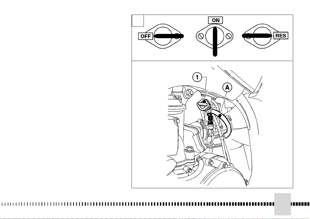
CONTROLES
GRIFOS DEL CARBURANTE
El grifo colocado a la izquierda del
depósito consta de tres posiciones:
OFF - cerrado; no sale carburante;
ON - abierto; el carburante sale del
conducto principal;
RES - reserva; el carburante sale del
conducto de reserva.
En el caso de que durante la marcha
notara dificultades en la alimentación,
ponga la palanca del grifo en posición
RES. Tras efectuar el abastecimiento
de carburante, llevar otra vez el grifo
en posición ON.
ATENCIÓN *: Tener cuidado a no
tocar el motor caliente cuando
se trabaja sobre el grifo
carburante.
El grifo lleva incorporado un filtro: la
acumulación de suciedad provoca
una disminución del pasaje de
carburante hacia el carburador. Por lo
tanto es necesario efectuar la
limpieza de la siguiente manera:
1- Eliminar el carburante del depósito,
desenganchar la tubería.
2- Remover el grifo, después del
desmontar los tornillos de fijación.
Limpiar el filtro de red con un
solvente.
3- Reensamblar el grifo efectuando
las operaciones inversas respecto al
montaje. Girar el grifo en posición
“ON” y comprobar que no hayan
pérdidas.
1- Rubinetto
A- Al carburatore
1 - Fuel valve
A - To the carburetor
1- Robinet
A- Au carburateur
1- Hahn
A- Zum Vergaser
1- Grifo
A- Al carburador
1
39
Page 40

CAVALLETTO LATERALE
Ogni motociclo è fornito di un
cavalletto laterale (1).
SIDESTAND
A sidestand (1) is supplied with
every motorcycle.
BEQUILLE LATERALE
Chaque motocycle est doté
d’une béquille latérale (1).
SEITLICHE FUSSRASTE
Jedes Motorrad ist mit einer
seitlichen (1) Fußraste
ausgestattet.
ATTENZIONE*: Il cavalletto è
progettato per supportare il
SOLO PESO DEL MOTOCICLO.
Non sedersi sul veicolo
utilizzando il cavalletto come
supporto; potrebbero
verificarsi delle rotture con
conseguenti gravi lesioni
personali.
Controllare periodicamente il
cavalletto laterale (vedi “Scheda
di manutenzione periodica”);
verificare che le molle non siano
danneggiate e che il cavalletto si
muova liberamente. Nel caso il
cavalletto fosse rumoroso,
lubrificare il perno (A) di
fissaggio.
WARNING*: The stand is designed to support the weight
of the MOTORCYCLE ONLY.
Do not sit on the motorcycle
using the stand for support
as this could cause structural failure to the stand and
could cause serious bodily
injury.
Periodically check the side
stand (see “Periodical
maintenance card”); check that
the springs are not damaged
and that the side stand freely
moves. If the side stand is
noisy, lubricate the fastening
pivot (A).
ATTENTION * : La béquille a
été projetée pour supporter
SEULEMENT LE POIDS DU
MOTOCYCLE. Ne jamais
s’asseoir sur le motocycle en
utilisant la béquille comme
support, car dans ce cas, on
court le risque
d’endommager la béquille et
de se blesser.
Contrôler la bequille latéral
périodiquement (tu vois "Fiche"
d'entretien périodique"); vérifier
que les ressorts ne soient pas
endommagés et que la bequille
latéral se remue librement.
Dans le cas la bequille latéral
devînt bruyant, lubrifier le pivot
(A) de fixation.
ACHTUNG* : Die Fußraste
wurde entworfen NUR DAS
GEWICHT DES MOTORRADS
zu halten. Sich nicht auf das
Fahrzeug setzen und die
Fußraste als Halter benutzen,
es könnten Brüche auftreten
mit nachfolgenden schweren
persönlichen Verletzungen.
Periodisch den Seitenständer
kontrollieren (sieht den "Zettel
von periodischer Wartung");
prüfen, daß den Federn nicht
geschadet wirst und daß der
Seitenständer es bewegt frei.
Der Seitenständer war in der Fall
lärmend, die Stütze (A) von
Befestigung schmieren.
40
Page 41

SOPORTE LATERAL
Cada motociclo está equipado
con un soporte lateral (1).
ATENCIÓN*: El soporte está
proyectado para soportar
SÓLO EL PESO DEL
MOTOCICLO. No sentarse
sobre el vehículo utilizando
el soporte como apoyo;
podrían producirse roturas
que conllevarían graves
lesiones personales.
Controlar periódicamente el
soporte lateral (ve "Ficha" de
manutención periódica);
averiguar que los muelles no
sean perjudicados y que el
soporte lateral se mueva
libremente. En el caso el
soporte lateral fuera ruidoso,
lubricar el perno (A) de fijado.
41
Page 42

C
ARBURANTE
Il motociclo monta un motore a due tempi
che richiede un’alimentazione di miscela
benzina-olio. Il carburante consigliato è
benzina SENZA PIOMBO a 98 ottani.
FUEL
The motorcycle is equipped with 2 stroke
engine that requires a gasoline-oil mixture.
Recommended fuel: premium grade unleaded fuel (R.O.N. 98).
CARBURANT
Le motocycle monte un moteur à deux
temps et il demande donc un mélange
essence-huile. Carburant recommandé:
essence SANS PLOMB à 98 octanes.
Nota*: Se il motore “batte in testa”
utilizzare un’altra marca di benzina o un
carburante con n° di ottani più elevato.
ATTENZIONE*: Se il motore continua a
“battere in testa” non utilizzarlo
ulteriormente; potrebbero verificarsi
gravi danni tra i quali il grippaggio.
Nota*: Non mischiare olii di tipo
sintetico e minerale.
ATTENZIONE*: La benzina è
estremamente infiammabile e può
diventare esplosiva in particolari
condizioni. Spegnere sempre il motore,
non fumare o avvicinare fiamme o
scintille nell’area dove si effettua il
rifornimento o si conserva il carburante.
ATTENZIONE*: Non riempire il serbatoio
oltre il limite inferiore del bocchettone di
carico. Dopo il rifornimento, accertarsi
della corretta chiusura del tappo (1) del
serbatoio.
Note*: Do not continue operation if the
engine pings or knocks. The engine will
be damaged and could seize.
WARNING*: If "knocking" or "pinging"
occurs, try a different brand of gasoline
or higher octane grade.
Note*: Do not mix synthetic and mineral
based oils.
WARNING*: Gasoline is extremely flammable and can be explosive under certain conditions. Always stop the engine
and do not smoke or allow flames or
sparks in the area where the motorcycle
is refueled or gasoline is stored.
WARNING*: Do not overfill the tank.
After refueling, make sure the tank cap
(1) is closed securely.
Nota* : Si le moteur “cogne”, utiliser
une autre marque d’essence, ou un
carburant avec indice d’octane plus
élevé.
ATTENTION * : Si le moteur “cogne”,
l’arrêter immédiatement, car il pourrait
gripper.
Nota * : Ne jamais mélanger huiles
synthétiques et minérales.
ATTENTION * : L’essence est une
matière très inflammable que, dans des
conditions particulières, peut devenir
explosive. Arrêter toujours le moteur, ne
pas fumer, ou approcher la flamme ou
étincelles à la zone de ravitaillement, ou
dans les lieux où on garde le carburant.
ATTENTION * : Ne jamais remplir le
réservoir au délà de la limite inférieure
de la goulotte de remplissage. Assurezvous que le bouchon (1) du réservoir
soit bien fermé.
42
Page 43

TREIBSTOFF
Das Motorrad besitzt einen Zweitakt-Motor,
der Öl-Benzin-Mischung-Versorgung
verlangt. Empfohlener Treibstoff ist
BLEIFREIES Benzin zu 98 Oktan.
CARBURANTE
El motociclo está dotado de un motor de
dos tiempos que requiere una mezcla
gasolina-aceite. El carburante aconsejado
es gasolina sin plomo de 98 octanos.
Anmerkung* : Wenn der Motor “klopft”
eine andere Benzinmarke oder einen
Treibstoff mit höherer Ottanzahl
benutzen.
ACHTUNG* : Wenn der Motor “klopft”
nicht weiter beanspruchen, es könnten
schwere Schäden unter anderem das
Festfressen auftreten.
WARNHINWEIS* : Keine synthetischen
Öle mit Mineralöle vermischen.
ACHTUNG* : Das Benzin ist äußerst
entzündbar und kann unter besonderen
Bedingungen explosiv werden. Den
Motor immer abschalten, nicht rauchen
oder sich mit Flammen oder Funken dem
Bereich, an welchem getankt oder
Treibstoff aufbewahrt wird, nähern.
ACHTUNG* : Den Tank nicht über die
untere Grenze des Einfüllstutzens füllen.
Nach dem Tanken sich vom richtigen
Verschluß (1) des Tankstopfens
vergewissern.
Notas*: Si el motor tiene martilleo de
válvulas, utilizar otra marca de gasolina
o un carburante con un número de
octanos más elevado.
ATENCIÓN*: Si el motor tiene martilleo
de válvulas no utilizarlo ulteriormente;
podrían producirse graves daños como
el agarrotamiento.
Notas*: No mezclar aceites de tipo
sintético y mineral.
ATENCIÓN*: La gasolina es
extremamente inflamable y en
condiciones particulares puede volverse
explosiva. Apagar siempre el motor, no
fumar y no acercar flamas o chispas en
el área en la que se efectúa la provisión
o se conserva el carburante.
ATENCIÓN*: No rellenar el depósito más
del límite inferior de la boca de llenado.
Tras la provisión, asegurarse que el
tapón (1) del depósito esté
correctamente cerrado.
43
Page 44

STARTER CARBURATORE
Il pomello (1) dello starter, posto
sul carburatore, viene azionato
per arricchire la miscela durante
l'avviamento.
Tirare il pomello verso l'alto per
attivare lo starter, agire
inversamente per disattivarlo.
STARTER
Start knob (1) set on the
carburettor is used to enrich the
mixture when starting the engine.
Pull knob highwards to activate
the starter, push lever
downwards to deactivate the
starter.
DEMARREUR
Le poignée de démarrage (1)
placé sur le carburateur, est
utilisé pour enrichir le mélange
pendant le démarrage.
Tirer le poignée vers le haut pour
activer le démarreur, presser le
levier en bas pour le désactiver.
VERGASERSTARTER
Der Startknopf (1) auf dem
Vergaser dient zur Ueberfettung
des Gemisches beim Anlassen.
Um die Starter zu oeffnen, den
Hebel nach oben aktivieren, um
die Startknopf zu schliessen in
umgekehrter Richtung
entaktivieren.
44
Page 45
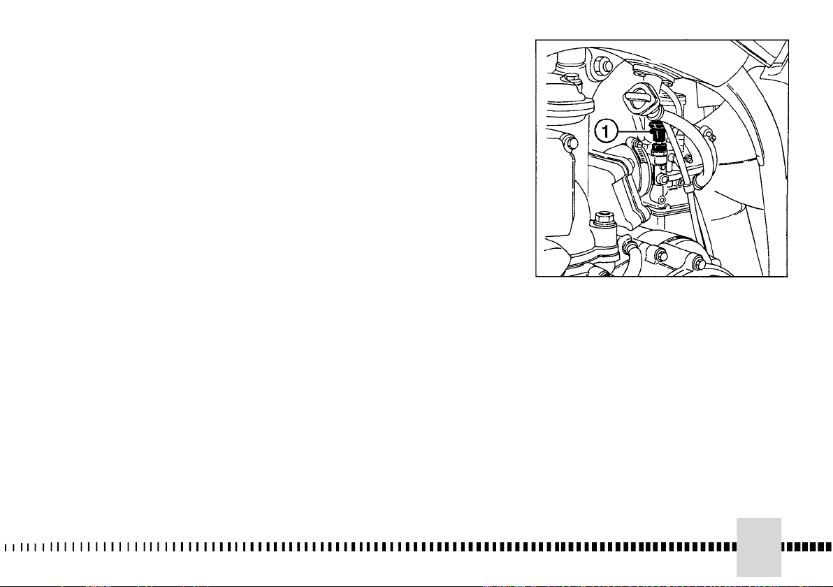
STARTER CARBURADOR
El pomo (1) del starter, colocada
en el carburador, se acciona para
enriquecer la mezcla durante el
arranque.
Tire el pomo hacia arriba para
activar starter, proceda
inversamente para cerrar.
45
Page 46

STRUMENTO DIGITALE, SPIE
(WR)
Il motociclo è equipaggiato con uno
strumento digitale sul quale
sono montate anche 2 spie
indicatrici: abbagliante ed indicatori
di direzione.
1- Spia BLU “Abbagliante”
2- Spia VERDE “Indicatori di
direzione”
Avviando il motore si illumina il
display dello strumento (colore
ambra).
NOTE
- Ad ogni avviamento del motore,
per i primi 2 secondi appare
la versione del SW di controllo;
terminata la fase di controllo,
lo strumento visualizza l’ultima
funzione impostata.
- Ad ogni spegnimento del motore,
cessa la visualizzazione delle
funzioni dello strumento.
- Il passaggio da una funzione
all’altra ed il relativo azzeramento,
deve essere effettuato mediante il
tasto SCROLL (A).
DIGITAL INSTRUMENT,
WARNING LIGHTS (WR)
The motorcycle is equipped with
a digital instrument; on the
instrument are located 2 warning
lights too: high beam and
blinkers.
1- BLUE warning light “HIGH
BEAM”
2- GREEN warning light
“BLINKERS”
Starting the engine the
instrument dislplay illuminates
(amber colour).
NOTES
- When start the engine, for the
first 2 seconds, the instrument
shows the version of the
checking SW; after the check,
the instrument shows the last
planned function.
- When the motorcycle engine is
OFF, the instrument doesn’t also
show its functions.
- To select the instrument
functions and to set to zero the
functions,
use the SCROLL knob (A).
INSTRUMENT DIGITAL,
VOYANTS (WR)
Le motocycle est équipé avec un
instrument digital sur lequel sont
montées 2 voyants indicateurs
aussi: de route et indicateurs de
direction.
1- Voyant BLEU “De route”
2- Voyant VERT “Indicateurs de
direction”)
En acheminant le moteur l'écran de
l'instrument (couleur ambre)
s'allume.
NOTES
À chaque démarrage du moteur,
pour les premier 2 secondes
apparaît la version du SW de
contrôle; terminée la phase de
contrôle, l’instrument visualise la
dernière fonction fondée.
-À chaque extinction du moteur, il
cesse la visualisation des fonctions
de l’instrument .
-Le passage d’une fonction à l’autre
et le zérotage relatif, il doit
être effectué par la touche SCROLL
(A).
DIGITALTACHOMETER,
KONTROLLEUCHTEN (WR)
Das Motorrad ist mit einem
Digitalinstrument ausgestattet, an
dem sich auch 2 Kontrolllampen
befinden: Fernlicht und Blinker.
1- Fernlichtkontrolle BLAU
2- Blinkerkontrolle GRÜN
Wenn der Motor gestartet wird,
schaltet sich die
Displaybeleuchtung
(bersteinfarben) am Instrument ein.
ANMERKUNGEN
- Wenn der Motor gestartet wird,
schaltet sich die
Displaybeleuchtung
(bersteinfarben) am Instrument ein.,
wird während der ersten 2
Sekunden die Version der SteuerSoftware angezeigt. Nach der
Überprüfungs-Phase wird am
Instrument die letzte eingestellte
Funktion angezeigt.
- Nach dem Abschalten des Motors
werden keine InstrumentenFunktionen mehr angezeigt.
- Das Umschalten von einer
Funktion zur nächsten, sowie das
entsprechende Nullstellen, muss
über die Taste SCROLL (A)
erfolgen
46
Page 47

INSTRUMENTO DIGITAL,
TESTIGOS (WR)
El motociclo es equipado con un
instrumento digital sobre el quale
2 testigos también son montados:
deslumbrante y indicadores de
dirección.
1- Testigo AZUL “ Deslumbrante ”
2- Testigo VERDE “ Indicadores de
dirección ”
Poniendo en marcha el motor se
ilumina la pantalla del instrumento
(color ámbar).
NOTAS
- Después del arranque del motor,
por los primeros 2 segundos
aparece la versión del SW de
control; acabada la fase
de control, el instrumento visualiza la
última función programada.
- A cada apagamiento del motor,
deja la visualización de las
funciones del instrumento.
- El paso de una función a la otra y a
la relativa puesta a cero,
tiene que ser efectuado a través de
la tecla SCROLL (A).
47
Page 48

- Le funzioni, che si possono
selezionare nell’ordine, sono le
seguenti:
1- SPEED / ODO (figura 1, pag 50)
2- SPEED / OROLOGIO (figura 2,
pag. 52)
3- SPEED / TRIP (figura 3, pag 52)
4- SPEED / CRONOMETRO
(figura 4, pag. 54)
1- SPEED / ODO (figura 1, pag 50)
.................
- The instrument functions are
the following, as shown below.
1- SPEED / ODO (figure 1, page
50)
2- SPEED / CLOCK (figure 2,
page 52)
3- SPEED / TRIP (figure 3, page
52)
4- SPEED / CHRONO (figure 4,
page 54)
1- SPEED / ODO (figure 1, page
50)
.................
-Les fonctions, qu’ils peuvent
sélectionner dans l’ordre, sont les
suivante:
1- SPEED / ODO (figure 1, page
50)
2- SPEED / (figure 2, page 52)
3- SPEED / TRIP (figure 3, page
52)
4- SPEED / CHRONOMETRE
(figure 4, page 54)
1- SPEED / ODO (figure 1, page
50)
.................
- Folgende Funktionen können
nacheinander in der angegebenen
Reihenfolge ausgewählt werden:
1- GESCHWINDIGKEIT /
GESAMT-KILOMETERZANZEIGE
(Abbildung 1, Seite 50)
2- GESCHWINDIGKEIT / UHR
(Abbildung 2, Seite 52)
3- GESCHWINDIGKEIT /
TEILSTRECKENKILOMETERZANZEIGE
(Abbildung 3, Seite 52)
4- GESCHWINDIGKEIT /
CHRONOMETER (Abbildung 4,
Seite 54)
5- GESCHWINDIGKEIT /
DREHZAHL (Ziffern-Anzeige)
(Abbildung 5, Seite 16)
1- GESCHWINDIGKEIT /
GESAMT-KILOMETERZANZEIGE
(Abbildung 1, Seite 50)
.................
48
Page 49

- Las funciones, que se pueden
seleccionar en el orden, son las
singuientes:
1- SPEED / ODO (figura 1, pag .
51)
2- SPEED / OROLOGIO (figura 2,
pag. 53)
3- SPEED / TRIP (figura 3, pag 53)
4- SPEED / CRONÓMETR O
(figura 4, pag. 55)
1- SPEED / ODO (figura 1, pag 51)
.................
49
Page 50

1- SPEED (Km/h o mph) / ODO
(figura 1)
- SPEED: velocità del veicoloIndicazione max: 299 Km/h o 299
mph;
- ODO: odometro- Indicazione max:
99999 Km;
Per passare da km a miles o da
miles a Km procedere nel modo
seguente:
1) visualizzare la figura 1, spegnere
il motore e premere il pulsante
SCROLL (A).
2) avviare il motore tenendo
premuto il pulsante SCROLL (A)
fino al momento in cui appare il
simbolo “Km/h”.
3) di seguito saranno visualizzati
alternativamente “Km/h” e “Mph
Miles”, premere nuovamente il
pulsante SCROLL (A) nel momento
che viene visualizzata l’unità di
misura che si intende
utilizzare.
1- SPEED (Km/h or mph) / ODO
(figure 1)
- SPEED: motorcycle speedmaximum value: 299 Km/h or
299 mph;
- ODO: odometer- maximum
value: 99999 km;
To replace kilometers with miles
or miles with kilometers proceed
as follows:
1) set to figure 1, stop the engine
and push the knob SCROLL (A);
2) start the engine pushing and
holding the button SCROLL (A)
until the symbol “Km/h” will be
displayed;
3) then the symbols “Km/h” and
“Mph Miles” will be displayed
alternatively.
Push again the SCROLL (A)
button when the unit you
wish to use is displayed.
1- SPEED (Km/h o mph) / ODO
(figure 1)
- SPEED: vitesse du véhicule Indication max: 299 km/h ou 299
mph
- ODO: odomètre - Indication max:
99999 km
Pour passer de km au miles ou de
miles à km procéder de la manière
suivante:
1) visualiser l’illustration 1, éteindre
le moteur et presser le bouton
SCROLL (A).
2) démarrer le moteur en tenant
pressé le bouton SCROLL (A)
jusqu'au moment où apparaîtra le
symbole “Km/h”.
3) ensuite, s'afficheront
alternativement "Km/h" et "Mph
Miles",
appuyer à nouveau sur le bouton
SCROLL (A) au moment où
s'affiche l'unité de mesure que l'on
souhaite utiliser.
1- SPEED (Km/h o mph) / ODO
(bild 1)
- SPEED: Motorradgeschwindigkeit
- maximaler Wert : 299
Km/h oder 299 mph;
- ODO: Kilometerzähler- maximaler
Wert: 99999 km;
Um Kilometer mit Meilen oder
Meilen mit Kilometern zu ersetzen
gehen Sie weiter wie folgt:
1) Bild 1 darzustellen, den Motor
anzuhalten und die Knauf
SCROLL (A) zu schieben.
2) Den Motor starten und dabei die
Taste SCROLL (A) solange
gedrückt halten, bis das Symbol
"Km/h" angezeigt wird.
3) Anschließend werden
abwechselnd “Km/h” und “Mph
Miles”
angezeigt. In dem Moment, in dem
die Einheit angezeigt wird,
die benutzt werden soll, erneut die
Taste SCROLL (A) drücken.
50
Page 51

1- SPEED (kmh o bien mph) / ODO
(figura 1)
- SPEED: velocidad del vehículo Indicación max : 299 kmh o bien
299 mph;
- ODO: odómetro- Indicación max:
99999 km;
Para pasar de km a miles o de miles
a km proceder en el modo siguiente:
1) visualizar la figura 1, apagar el
motor y comprimir el pulsante
SCROLL (A).
2) Arrancar el motor manteniendo
apretado el botón SCROLL (A)
hasta el momento en el que aparece
el símbolo “ kmh o bien”.
3) a continuación, se visualizarán
alternativamente “Km/h” y
“Mph Miles”; volver a apretar el botón
SCROLL (A) en el momento
en que se visualiza la unidad de
medida que se quiere
utilizar.
51
Page 52

2- SPEED / CLOCK (figura 2)
- SPEED: velocità- Indicazione
max: 299 km/h o 299 mph;
- CLOCK: orologio- Indicazione da
0:00 a 23:59:59.
Per regolare l’orologio, premere il
pulsante SCROLL (A) per più
di 3 secondi per incrementare le
ore; rilasciato il pulsante, dopo
3 secondi è possibile incrementare
i minuti.
3- SPEED / TRIP 1 (figura 3)
- SPEED: velocità- Indicazione
max: 299 km/h o 299 mph
- TRIP 1: distanza- Indicazione
max: 999, 9 km (il dato verrà perso
per tensione inferiore a 6V).
Per regolare il TRIP, premere il
pulsante SCROLL (A) per più di 3
secondi.
2- SPEED / CLOCK (figure 2)
- SPEED: motorcycle
speedmaximum value: 299 Km/h
o 299 mph;
- CLOCK: clock- Reading from
0:00 to 23:59:59.
To reset the clock, push the knob
SCROLL (A) for more than 3
seconds in order to increase the
hours; release the knob and
then, after 3 seconds, it is
possible to increase the minutes.
3- SPEED / TRIP 1 (figure 3)
- SPEED: motorcycle
speedmaximum value: 299 Km/h
o 299 mph
- TRIP 1: distance- maximum
value: 999.9 km (the data will be
lost with voltage lower than 6V).
To setup the TRIP, push the
SCROLL (A) button holding down
more than 3
seconds.
2- SPEED / CLOCK (figure 2)
- SPEED: vitesse du véhicule Indication max: 299 km/h ou 299
mph;
-CLOCK: montre- Indication da
0:00 a 23:59:59.
Pour régler la montre, presser le
bouton SCROLL (A) pour plus de
3 secondes pour développer les
heures; relâché le bouton, après
3 secondes il est possible de
développer les minutes;
3- SPEED / TRIP 1 (figure 3)
- SPEED: vitesse du véhicule Indication max: 299 kmh ou 299
mph;
-TRIP 1: distance- Indication max:
999, 9 km (la donnée viendra
perdue pour tension inférieure à
6V).
Pour réglero le TRIP, presser le
bouton SCROLL (A) pour plus de 3
secondes.
2- SPEED / CLOCK (bild 2)
- SPEED:Motorradgeschwindigkeit maximaler Wert : 299 Km/h oder 299
mph;
- CLOCK: Uhr- Die Uhrlektüre ist von
0:00 bis 23:59:59.
Um die Uhr umzustellen, schieben
Sie der Knauf (A) denn mehr
als 3 Sekunden, um die Stunden
zuzunehmen; Freilassung der
Knauf und dann ist es nach 3
Sekunden möglich, die Minuten
zuzunehmen.
3- SPEED / TRIP 1 (Bild 3)
- SPEED: Motorradgeschwindigkeit maximaler Wert : 299
Km/h oder 299 mph;
- TRIP 1: Entfernungmaximaler Wert:
999.9 km (die Daten werden
verloren mit Spannung niedriger als
6V).
Zum Einstellen auf TRIP
(TEILSTRECKENKILOMETERZANZEIGE)
die Taste SCROLL (A) länger als 3
Sekunden drücken.
52
Page 53

2- SPEED /CLOCK (figura 2)
- SPEED: velocidad del vehículo Indicación max : 299 kmh o
bien 299 mph;
- CLOCK: reloj- Indicación de 0:00 a
23:59:59
Para regular el reloj, comprimir el
pulsante SCROLL (A) por más
que 3 segundos para incrementar
las horas; concedido el pulsante,
después de 3 segundos es posible
incrementar los minutos.
3- SPEED / TRIP 1 (figura 3)
- SPEED: velocidad del vehículo Indicación max: 299 kmh o bien
299 mph;
- TRIP 1: distancia- Indicación max:
999, 9 km (el dato será perdido
por tensión inferior a 6V).
Para regular el TRIP, comprimir el
pulsante SCROLL (A) por más
que 3 segundos.
53
Page 54

4- SPEED / CRONOMETRO
(STP) (figura 4)
- SPEED: velocità- Indicazione
max: 299 km/h o 299 mph;
- STP 1: tempo di percorrenza km
- mi.
- Indicazione da 0:00 a 99:59:99 (
il dato verrà perso per tensione
inferiore a 6V).
Il contatore STP si attiva
premendo, a funzione visualizzata,
il tasto pulsante SCROLL (A) per
più di 3 secondi.
- 1° intervento: attivazione
funzione;
- 2° intervento: stop ai contatori;
- 3° intervento: azzeramento STP;
- 4° intervento: attivazione
funzione;
- 5° intervento: stop ai contatori;
.............................
e così di seguito
4- SPEED / CHRONO (STP)
(figure 4)
- SPEED: motorcycle
speedmaximum value: 299 Km/h
o 299 mph;
- STP 1: miles/kilometers
covered time;
- Reading from 0:00 to 99:59:59
(the data will be lost with voltage
lower than 6V).
To activate the function STP 1,
push the knob SCROLL (A) for
more than 3 seconds.
- 1st step: function ON;
- 2nd step: stop to the counters;
- 3rd step: STP 1 zero-setting; - -
- 4th step: function ON;
- 5th step: stop to the counters;
.............................
and so following
4- SPEED / CHRONOMETRE
(STP) (figure 4)
- SPEED: vitesse du véhicule Indication max: 299 kmh ou 299
mph;
-STP 1: temps de parcours en kmmi
- Indication de 0:00 à 99:59:59 (la
donnée viendra perdue pour
tension inférieure à 6V).
Le compteur STP on active en
pressant le bouton SCROLL (A),
pour plus de 3 secondes.
- Phase 1: activation fonction;
- Phase 2: stop aux compteurs;
- Phase 3: zérotage STP
- Phase 4: activation fonction;
- Phase 5: stop aux compteurs;
.............................
et si de suite
4- SPEED / CRHOMETER (STP)
(Bild 4)
- SPEED:
Motorradgeschwindigkeit maximaler Wert : 299
Km/h oder 299 mph;
- STP 1: miles/kilometers deckte
Zeit
- Das Lesen von 0:00 bis
99:59:59 (die Daten werden
verloren mit Spannung niedriger
als 6V).
Um der Funktion STP zu
aktivieren, drängen Sie der Knauf
SCROLL (A) auf mehr als 3
Sekunden.
1. Schritt: Funktion AUF;
2. Schritt: halten Sie zu-Höhle
Schaltern;
3. Schritt: STP 1 Neueinstellung;
REISE 1 und AVS 1 DatenNeueinstellung;
4. Schritt: Funktion AUF;
5. Schritt: halten Sie zu-Höhle
Schaltern;
.............................
und das Folgen so
54
Page 55

4- SPEED / CRONÓMETR O (STP)
(figura 4)
- SPEED: velocidad del vehículo Indicación max: 299 kmh o bien
299 mph;
- STP 1: tiempo de recorrido km-mi
- Indicación de 0:00 a 99:59:59 ( el
dato será perdido por tensión inferior
a 6V).
El contador STP se activa
comprimiendo el pulsante SCROLL
(A)
por más que 3 segundos.
- Fase 1: activación función;
- Fase 2: stop a los contadores;
- Fase 3: puesta a cero STP;
- Fase 4: activación función;
- Fase 5: stop a los contadores;
.............................
y tan en seguida
55
Page 56

COMANDO GAS
La manopola (1) del gas é situata
sulla parte destra del manubrio.
La posizione del comando sul
manubrio può essere regolata
allentando le due viti di fissaggio.
THROTTLE CONTROL
The throttle (1) knob, located on
the right-hand side of the
handlebar.
The position on the
handlebar can be adjusted by
loosening the two fixing screws.
POIGNEE DES GAZ
La poignée (1) des gaz est
placée à droite du guidon.
La position de la commande sur
le guidon peut être réglée en
desserrant les deux vis de
fixation.
GASANLASSER
Der Griff (1) für das Gas, der sich
auf der rechten Seite des Lenkers
befindet.
Die Schaltungs-Position
auf dem Lenker kann durch
Lockern der beiden
Befestigungsschrauben
eingestellt werden.
AVVERTENZA
Non dimenticare di stringere le
viti (A) dopo la regolazione.
COMANDO FRENO
ANTERIORE
La leva (2) del freno è situata sul
lato destro del manubrio e
comanda il freno anteriore.
La posizione del comando sul
manubrio può essere regolata
allentando le due viti di fissaggio.
AVVERTENZA
Non dimenticare di stringere le
viti (B) dopo la regolazione.
56
CAUTION
Do not forget to tighten the
screws (A) after the adjustment.
FRONT BRAKE
CONTROL
The brake control lever (2) is
situated on the right-hand side of
the handlebar and controls the
front wheel brake.
The position on the handlebar
can be adjusted by loosening
the two fixing screws.
CAUTION
Do not forget to tighten the
screws (B) after the adjustment.
ATTENTION
N’oubliez pas de serrer les vis
(A) après le réglage.
COMMANDE
FREIN AVANT
La manette (2) de commande du
frein avant est placée du côté
droit du guidon.
La position de la commande sur
le guidon peut être réglée en
desserrant les deux vis de
fixation.
ATTENTION
N’oubliez pas de serrer les vis
(B) après le réglage.
MAN BEACHTE
Nach der Einstellung nicht
vergessen, die Schrauben (A)
anzuziehen.
STEUERUNG
VORDERBREMSE
Der Bremshebel (2) befindet sich
auf der rechten Seite des Lenkers
und steuert die Vorderbremse.
Die Schaltungs-Position auf dem
Lenker kann durch Lockern der
beiden Befestigungsschrauben
eingestellt werden.
MAN BEACHTE
Nach der Einstellung nicht vergessen, die Schrauben (B)
anzuziehen.
Page 57
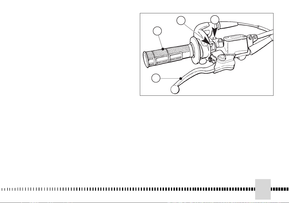
MANDO DEL GAS
Ud. puede regular la maneta (1)
de la mariposa.
La posición de mando sobre el
manillar se puede regular
aflojando los dos tornillos de
fijación.
ADVERTENCIA
No se olvide de apretar los
tornillos (A) después de la
regulación.
MANDO FRENO
DELANTERO
La palanca (2) del freno se
encuentra en la parte derecha del
manillar y manda el freno
delantero.
La posición de mando sobre el
manillar se puede regular
aflojando los dos tornillos de
fijación.
ADVERTENCIA
No se olvide de apretar los
tornillos (B) después de la
regulación.
B
A
A
1
1
2
2
B
57
Page 58

BLOCCASTERZO
(escluso USA/CDN)
Il motociclo è fornito di un
bloccasterzo (1) posto sul lato
destro dello sterzo.
Per bloccare lo sterzo:
inserire la chiave nella serratura
e girare in senso antiorario.
Spingerla verso l'interno e, se
necessario, girare il manubrio nei
due sensi.
Girare la chiave in senso orario
ed estrarla dalla serratura.
Per sbloccare lo sterzo, operare
inversamente.
STEERING LOCK
(USA/CDN excluded)
The motorcycle is equipped with
a steering lock (1) on the righthand side of the steering head
tube. To lock it, proceed as
follows:
- place key in lock and turn anticlockwise;
- push key inwards (if necessary,
turn to and from);
- turn key clockwise and remove
it from lock.
To unlock the steering lock,
reverse the above procedure.
BLOC DE DIRECTION
(USA/CDN exclu)
A droite de la moto a été
assemblé un bloc-direction (1).
Pour bloquer la direction agir
comme suit:
- introduire la clé dans la serrure
et la tourner en sens
antihoraire;
- pousser la clé vers l’intérieur et,
si nécessaire, tourner le guidon
dans les deux sens;
- tourner la clé en sens horaire et
l’extraire de la serrure.
Pour debloquer la direction,
effectuer les même operations,
mais en sens inverse.
LENKERBLOCKUNG
(nach USA/CDN)
Das Motorrad ist mit einer
Lenkerblockung ausgerüstet (1),
die sich auf der rechten Seite des
Lenkers befindet.
Um den Lenker zu blockieren,
folgendermassen vorgehen:
Den Schlüssel in das Schloss
stecken und dem Uhrzeigersinn
entgegen drehen.
Ihn nach innen drücken, und,
wenn nötig, den Lenker in beide
Richtungen drehen. Den
Schlüssel in Uhrzeigersinn
drehen und ihn aus dem Schloss
herausziehen.
Um die Lenkung freizugeben,
umgekehrt operieren.
58
Page 59

BLOQUEO DE LA DIRECCION
(excluido USA/CDN)
La motocicleta está provista de
un bloqueador (1) de dirección
que se encuentra en la parte
derecha de la manillar de
dirección.
Para bloquear la dirección actúe
como se indica a continuación:
Coloque la llave en la cerradura y
gire en sentido antihorario.
Empuje hacia dentro, y si fuera
necesario, gire el manillar en los
dos sentidos.
Gire la llave en el sentido de las
manecillas del reloj y extráigala
de la cerradura.
Para debloquear la dirección,
cumpla las operaciones en
sentido inverso.
59
Page 60
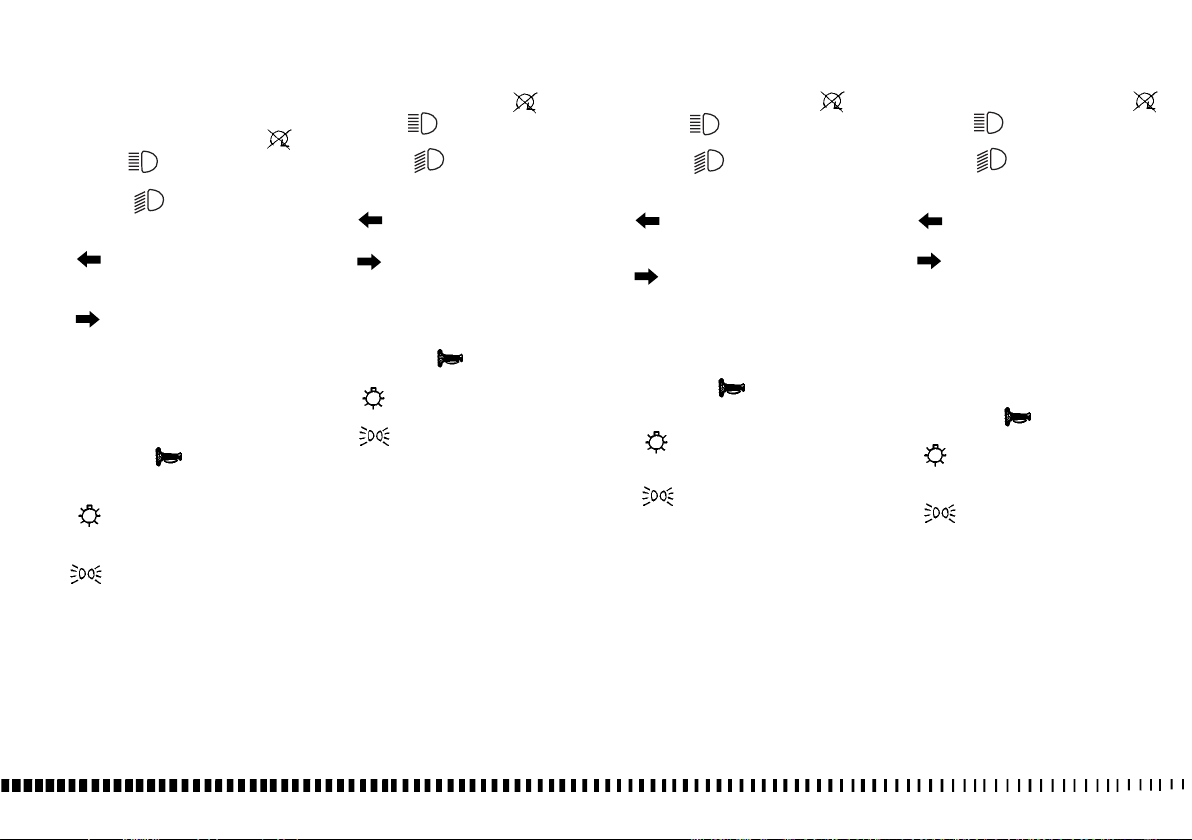
COMMUTATORE SUL
MANUBRIO (escluso USA/CDN)
Il commutatore sinistro ha i
seguenti comandi:
1) Pulsante arresto motore ( )
2) "HI" ( ) Comando
selezione luce abbagliante
"LO" ( ) Comando
selezione luce anabbagliante
3) TURN
= Attivazione indicatori di
direzione sinistri (ritorno
automatico)
= Attivazione indicatori di
direzione destri (ritorno
automatico)
Per disattivare l’indicatore,
premere sulla levetta di comando
una volta che è ritornata al
centro.
4) HORN = ( ) avvisatore
acustico.
5) LIGHTS
= Comando accensione
luci anabbaglianti ed
abbaglianti
= Comando accensione
luci di posizione
G = Spento
HANDLEBAR COMMUTATOR
(USA/CDN excluded)
1) Engine stop button ( )
2) HI = ( ) Selection control
High beam
LO = ( ) Selection control
of Low beam
3) TURN
= Activation of left turn
indicators (self cancelling)
= Activation of right turn
indicators (self cancelling)
To deactivate the indicator,
press the control lever after its
returning to center.
4) HORN = ( ) Warning horn
5) LIGHTS
= Lighting control of low-
beams and high beam.
= Lighting control of
position lights.
G
= Off
COMMUTATEUR SUR LE
GUIDON (exclu USA/CDN)
1) Bouton d’arret moteur ( )
2) HI = ( ) Commande
sélection feu de route
LO = ( ) Commande
sélection feu de croisement
3) TURN
= Activation indicateurs de
direction gauches (retour
automatique
= Activation indicateurs de
direction droits (retour
automatique).
Pour désactiver l’indicateur,
presser le levier de commande
une fois retourné au centre.
4) HORN = ( ) Avertisseur
acoustique.
5) LIGHTS
= Commande allumage
feu de croisement et feu de
route
= Commande allumage
feu de stationnement
G = Eteint
UMSCHALTER AUF DEM
LENKER (nuhr USA/CDN)
1) Druckknopf Motoranhalten ( )
2) HI = ( ) Wahlknopf
Fernlicht
LO = ( ) Wahlknopf
Abblendlicht
3) TURN
= Linke Richtungsanzeiger
(automatische Rückstellung)
= Rechte
Richtungsanzeiger
(automatische Rückstellung).
Um die Anzeiger ausser Tätigkeit
zu setzen, drücken Sie den
Schalthebel, wenn er in die
mittlere Stellung zurückgekehrt
ist.
4)
HORN = ( ) Hupe
5) LIGHTS
= Anzündung
Abblendlichter und
Fernlichter
= Anzündung Parklichter
G
= Aus
PULSANTE ARRESTO
MOTORE (USA/CDN)
Sul lato sinistro del manubrio, in
prossimità del comando frizione,
si trova il pulsante (1) di arresto
motore.
60
ENGINE STOP BUTTON
(USA/CDN)
On the left side of handlebar,
near clutch control, the engine
sto button (1) is set.
BOUTON D'ARRET MOTEUR
(USA/CDN)
Ce bouton est placé sur le côté
guache du guidon, auprès la
commande (1) embrayage.
DRUCKKNOPF MOTORANHALTEN (USA/CDN)
Auf der linken Seite der Lenkstange, neben der Kupplungssteuerung, befindet sich der
Druckknopf (1) zum
Motoranhalten.
Page 61
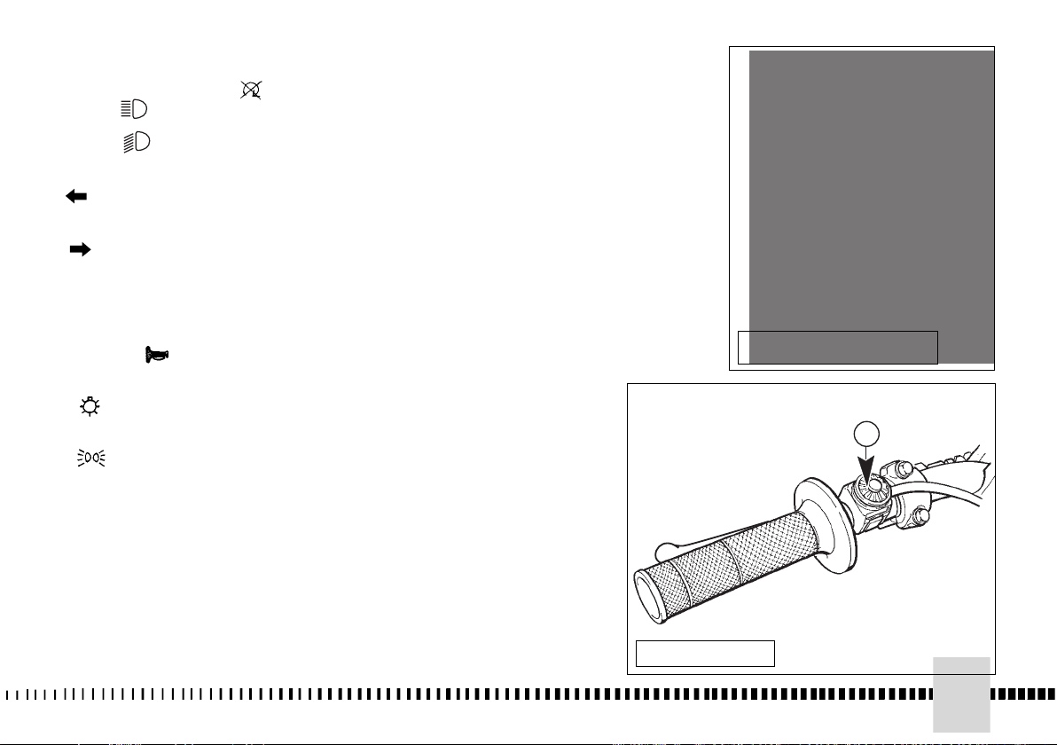
CONMUTADOR EN EL
1
MANILLAR (excluido USA/CDN)
1) Pulsador parada motor ( )
2) HI = ( ) mando selección
luz deslumbrante
LO = ( ) mando selección
luz de cruce
3) TURN
= activación indicadores de
dirección izquierdos
(retorno automático).
= Activación indicadores de
dirección derechos (retorno
automático)
Para desactivar el indicador
pulse la palanca de mando
cuando ha vuelto al centro.
4) HORN = ( ) Avisador
acústico.
5) LIGHTS
= mando encendido
luces de cruce y
deslumbrantes
= mando encendido
luces de estacionamiento
G= Apagado
UUSSAA//CCDDNN
EEXXCCLLUUDDEEDD
11
PULSADOR PARADA MOTOR
(USA/CDN)
En la parte izquierda del manillar,
cerca del mando del embrague
se encuentra el pulsador (1) de
parada del motor.
UUSSAA//CCDDNN
61
Page 62

COMANDO FRIZIONE
La leva della frizione è situata sul
lato sinistro del manubrio ed è
munita di protezione.
Il supporto della leva è provvisto
di una vite di registro (1) per
regolare il gioco del cavo della
frizione (vedere pag 94).
La leva può essere regolata per
adattarsi alla vostra posizione di
guida.
CLUTCH CONTROL
The clutch lever is located on the
left-hand side of the handlebar
and is protected against dirt
filtering in. The lever support is
provided with adjusting screw (1)
to regulate clutch wire free play
(see on page 94). The clutch
lever can be adjusted to suit your
driving position.
COMMANDE DE L’EMBRAYAGE
Le levier de l'embrayage est situé
à gauche sur le guidon et il est
muni d'une protection.
Support du levier avec vis (1)
pour régler le jeu du câble
d’embrayage (voir page 94).
Régler le levier pour l’adapter à
votre position de conduite.
KUPPLUNGSSTEUERUNG
Der Kupplungshebel befindet
sich auf der linken Seite des
Lenkers und ist mit einer
Schutzvorrichtung ausgestattet.
Der Hebelhalter ist mit einer
Einstellschraube (1) ausgestattet,
um das Spiel der
Kupplungsleitung einzustellen
(Sihe Seite 94). Der Hebel kann
eingestellt werden, um sich Ihrer
Fahrstellung anzupassen.
AVVERTENZA
Non dimenticare di stringere le
viti (C) dopo la regolazione.
62
CAUTION
Do not forget to tighten the
screws (C) after the adjustment.
ATTENTION
Ne pas oublier de resserrer les
vis (C) après le réglage.
MAN BEACHTE
Nicht vergessen, die Schrauben
(C) nach der Einstellung
anzuziehen.
Page 63
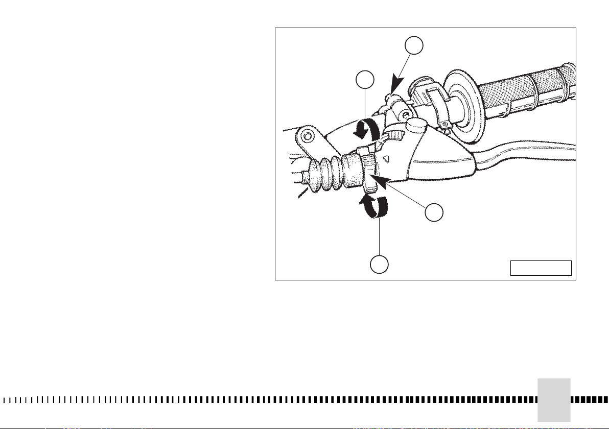
MANDO EMBRAGUE
La palanca del embrague está
situada a la izquierda de la
manillar y está dotada de
protección.
El soporte de la palanca está
dotado de un tornillo de
regulación (1) para regular el
juego del cable del embrague
(véaser pag. 95). La palanca
puede regularse para adaptarla a
su posición de manejo.
ADVERTENCIA
No se olvide de apretar los
tornillos (C) después de la
regulacion.
A: Per diminuire il gioco
B: Per aumentare il gioco
A: To decrease clearance
B: To increase clearance
A:Pour diminuer le jeu
B:Pour augmenter le jeu
A:
das Spiel zu verringern
B:
das Spiel zu erhoehen
A: para disminuir el juego
B: para aumentar el juego
B
B
A
A
C
C
1
1
USA-CDN
63
Page 64

COMANDO FRENO
POSTERIORE
Il pedale (1) di comando del freno
posteriore si trova sul lato destro
del motociclo. Un interruttore di
stop (escluso USA-CDN) all'atto
della frenata, provoca
l'accensione della lampada del
fanale posteriore.
REAR BRAKE
CONTROL
The rear brake control (1) is
placed on the right-hand side of
the motorcycle. A stop switch
(USA-CDN excluded) during
braking action, causes the rear
light to come on.
COMMANDE FREIN ARRIERE
La pédale (1) de commande du
frein arrière se trouve du côté
droit de la moto. Dans l'action de
freinage, un interrupteur d’arrêt
(exclu USA-CDN) allume le feu
arrière.
PEDAL ZUR STEUERUNG DER
BREMSE
Das Pedal (1) zur Steuerung der
hinteren Bremse befindet sich
auf der rechten Seite des
Motorrads. Bei der Bremsung
laesst ein Stoppschalter (nuhr
USA-CDN) die Ruecklichtlampe
aufleuchten.
64
Page 65
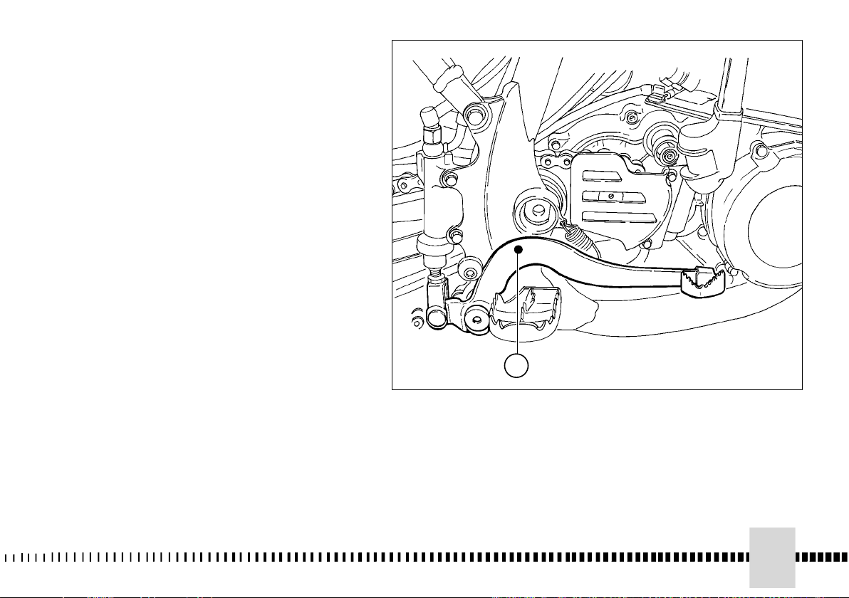
MANDO DEL FRENO TRASERO
El pedal (1) del mando del freno
trasero se encuentra a la
derecha de la motocicleta.En el
momento del
frenado, un interruptor de stop
(excluido USA-CDN) provoca el
encendido de la lámpara del faro
trasero.
1
65
Page 66

COMANDO CAMBIO
La leva (1) è posta sul lato
sinistro del motore. Dopo ogni
cambio di marcia ritorna
automaticamente nella posizione
centrale..
Si innesta la prima marcia
spingendo in basso la leva; per
tutte le altre marce spingerla in
alto.
La posizione della leva sull'albero
può essere variata. Per effettuare
questa operazione occorre
allentare la vite, togliere la leva e
porla in una nuova posizione
sull'albero.
Bloccare la vite ad operazione
effettuata.
AVVERTENZA*: Non cambiare le
marce senza disinnestare la
frizione e chiudere il gas. Il motore
potrebbe andare “fuorigiri” e
subire danni.
ATTENZIONE*: Non rallentare
scalando le marce quando ci si
trova ad una velocità che potrebbe
portare il motore “fuorigiri” oppure
far perdere aderenza alla ruota
posteriore, se si selezionasse la
velocità immediatamente inferiore.
PEDALE AVVIAMENTO
Il pedale (1) è posto sul lato
destro del motociclo.
GEAR SHIFT CONTROL
The lever (1) is placed on the lefthand side of the engine. After every
shift, the lever automatically returns
to its central position. First gear is
engaged by pushing the lever
downwards; all the other gears are
engaged, by pushing the lever
upwards.
The position of the gear shift lever
on the shaft can be varied by:
- loosening screw;
- pulling lever out;
- placing lever in new position on
the shaft whem the operation is
over tighten the screw and then
tightening the screw.
CAUTION*: Do not shift gears
without disengaging the clutch and
closing the throttle. The engine
could be damaged by overspeed
and shock.
WARNING*: Do not downshift when traveling at a speed that would force the
engine to overrev in the next lower gear,
or cause the rear wheel to lose traction
.
KICKSTART PEDAL
The kickstart pedal (1) is situated
on the right-hand side of the
COMMANDE DU
CHANGEMENT DE VITESSES
Le levier (1) est placé sur le côté
gauche du moteur. Après chaque
changement de vitesse il revient
automatiquement dans sa
position centrale.
On introduit la première vitesse
en poussant le levier en bas;
pour toutes les autres vitesses le
pousser en haut.
La position du levier sur l’arbre
peut être modifiée.
Pour effectuer cette opération il
faut desserrer la vis, enlever le
levier et le placer dans une
nouvelle position sur l’arbre.
Une fois l’opération terminée,
serrer la vis.
AVIS * : Ne jamais changer de
vitesse sans débrayer et sans
fermer la poignée des gaz.
Autrement, le moteur pourrait
“s’emballer” et donc, subir des
dommages.
ATTENTION * : Ne jamais ralentir
en insérant une vitesse inférieure
quand la vitesse atteinte est telle
à “emballer” le moteur. Dans ce
cas, le pneu arrière pourrait
perdre d’adhérence.
PEDALE DE DEMARRAGE
MOTEUR
La pédale (1) est située du côté
droite de la moto.
WECHSELGETRIEBESTEUERUNG
Der Hebel (1) befindet sich auf der
linken Seite des Motors. Nach
jeder Gangumschaltung kehrt er
automatisch in die Zentrallstellung
zurück. Man schaltet den ersten
Gang ein, indem man den Hebel
nach unten drückt; für alle
anderen Gänge ihn nach oben
drücken. Die Stellung des Hebels
auf der Welle kann verändert
werden. Um diesen Arbeitsgang
durchzuführen, muss man die
Schraube lockern, den Hebel
abnehmen und ihn in einer neuen
Stellung auf der Weille anbringen.
Nach der Operation die Schraube
anziehen.
WARNHINWEIS* : Nicht die Gänge
herausnehmen, ohne vorher die
Kupplung ausgekuppelt und das
Gas geschlossen zu haben. Der
Motor könnte “auf Touren”
gebracht werden und Schäden
erleiden.
ACHTUNG* : Nicht durch
Herunterschalten der Gänge
verlangsamen bei einer
Geschwindigkeit, die den Motor
“auf Touren” bringen könnte oder
die Hinterradhaftung verlieren
läßt, falls sofort die untere
Geschwindigkeit gewählt wird.
ANLASSPEDAL
Das Pedal (1) befindet sich auf
der recht Seite des Motorrads.
66
Page 67
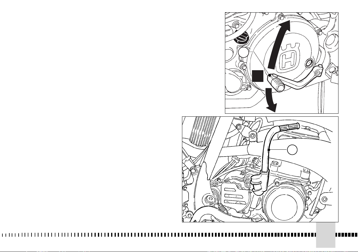
MANDO DE CAMBIO
La palanca (1) se encuentra a la
izquierda del motor. Después de
cada cambio de marcha regresa
automáticamente a la posición
central.
Se embraga la marcha primera
empujando hacia abajo la
palanca; para las restantes
marchas empujar hacia arriba.
La posición de la palanca en el
árbol puede variarse. Para
efectuar esta operación se
necesita aflojar el tornillo, quitar
la leva y colocarla en otra
posición en el árbol.
Bloquee el tornillo una vez
efectuada la operación.
ADVERTENCIA *: No cambiar las
marchas sin desembragar y
cerrar el gas. El motor podría ir
“fuera revoluciones” y sufrir
daños.
ATENCIÓN * : No reducir las
marcha cuando se tiene una
velocidad que podría llevar el
motor “fuera revoluciones” o
causar pérdida de adherencia a
la rueda trasera, si se
seleccionara la velocidad justo
inferior.
PEDAL DE ARRANQUE
El pedal (1) se encuentra en el
lado derecha de la motocicleta.
5
4
1
3
2
N
1
1
67
Page 68

ISTRUZIONI PER L'USO DEL MOTOCICLO
RIDING
MODE D’EMPLOI DE LA MOTO
CONTROLLI PRELIMINARI
ATTENZIONE!
Esaminate attentamente questa lista prima di
guidare per evitare incidenti o guasti durante
la marcia.
AVVERTENZA*: Non avviare il motore
quando il regolatore di tensione è
scollegato dall’impianto elettrico (WR;
Enduro USA/CDN)
1. Controllate tutti i liquidi
A. Livello olio trasmissione.
B. Livello carburante.
C. Livello liquido di raffreddamento.
Accertarsi che tutti i tappi siano stati
correttamente installati.
ATTENZIONE*: Non rimuovere il tappo del
radiatore a motore caldo!
2. Controllare tutti i comandi
A. Manopola del gas.
B. Leva della frizione.
Assicuratevi che le trasmissioni flessibili
non siano danneggiate e scorrano
liberamente.
3. Controllare i freni
Accertarsi che non vi siano perdite di olio
e che le tubazioni non siano usurate.
Controllare il funzionamento.
4. Controllare le sospensioni
Comprimere la forcella e la sospensione
posteriore.
Controllare che non vi siano perdite di
olio ed accertarsi del corretto
funzionamento.
BEFORE EVERY RIDE MAKE FOLLOWING
CHECKS
WARNING!
Before each ride, to prevent accidents or
failures during ride, make sure to go through
following list.
CAUTION*: Don’t start the engine while
voltage regulator is disconneted from main
wiring harness (WR; Enduro USA/CDN)
1. Check all fluids
A. transmission oil level
B. fuel level
C. coolant level
Make sure all caps are properly adjusted.
WARNING*: Don’t remove radiator cap when
hot!
2. Check all controls
A. Throttle handgrip
B. Clutch lever device
Make sure cables are not damaged and
turn smoothly.
3. Check brakes
Look for brake fluid leaks and worn cables.
Check for proper functioning.
4. Check suspensions
Compress fork and rear suspensions. Look
for oil leaks and ensure proper functioning.
CONTROLES PRELIMINAIRES
ATTENTION!
Examinez attentivement cette liste avant de
partir , pour éviter tout incident ou toute
pendant la marche.
ATTENTION * : Ne jamais démarrer le
moteur lorsque le régulateur de tension
est débranché de l’installation électrique,
(WR; Enduro USA/CDN).
1. Contrôle des liquides
A. Niveau d’huile/transmission
B. Niveau du carburant
C. Niveau du liquide de refroidissement
S’assurer que tous les bouchons soient
mis en place correctement.
ATTENTION * : Ne jamais ôter le
bouchon du radiateur quand le moteur
est encore chaud!
2. Contrôle des commandes
A. Poignée des gaz
B. Levier d’embrayage
S’assurer que les transmissions flexibles
ne soient pas endommagées et glissent
librement.
3. Contrôle des freins
S’assurer qu’il n’y ait pas de pertes d’huile
et que les tubes ne soient pas détériorés
Contrôler le fonctionnement.
4. Contrôle des suspensions
Comprimer la fourche et la suspension
arrière.
Contrôler qu’il n’y a pas de pertes d’huile et
s’assurer que le fonctionnement soit
correct.
68
Page 69

DASS MOTORRAD
VORKONTROLLEN
ACHTUNG!
Prüfen Sie aufmerksam diese Liste vor dem
Fahren, um Unfälle oder Defekte zu vermeiden.
ACHTUNG* : Den Motor nicht anlassen,
wenn der Spannungsregler von der
elektrischen Anlage abgetrennt ist (WR ;
Enduro USA/CDN).
1. Kontrollieren Sie alle Flüssigkeiten
A. Pegel Antrieb.
B. Treibstoffpegel.
C. Kühlflüssigkeitspegel.
Sich vergewissern, dass alle Stöpsel korrekt
angebracht worden sind.
ACHTUNG* : Nicht den Kühlerstopfen bei
warmem Motor abnehmen !
2. Alle Steuerungen kontrollieren
A. Griff für das Gas.
B. Kupplungshebel.
Vergewissern Sie sich, dass die flexiblen
Übersetzungen nicht beschädigt worden
sind und dass sie frei beweglich sind.
3. Die Bremsen kontrollieren
Sich vergewissern, dass keine Ölverluste
bestehen und dass die Leitungen nicht
abgenutzt sind.
Die Funktion kontrollieren.
4. Die Aufhängungen kontrollieren
Die Gabel und die hintere Aufhängung
zusammendrücken.
Kontrollieren, ob keine Ölverluste bestehen
und sich der korrekten Funktion
vergewissern.
INSTRUCCIONES PARA EL USO
DE LA MOTOCICLETA
CONTROLES PRELIMINARES
ATENCION!
Examine atentamente esta lista antes de
conducir la moto a fin de evitar accidentes o
averías durante la marcha.
ATENCIÓN *: No poner en marcha el motor
cuando el regulador de tensión está
desconectado de la instalación eléctrica
(WR; Enduro USA/CDN).
1. Controle todos los líquidos
A. Nivel aceite transmisión
B. Nivel carburante
C. Nivel líquido de enfriamiento
Asegúrese de que todos los tapones se
encuentren instalados correctamente.
ATENCIÓN *: ¡No remover el tapón del
radiador cuando el motor está caliente!
2. Controle todos los mandos
A. Maneta de la mariposa
B. Palanca del embrague
Asegúrese de que las transmisiones flexibles
no estén dañadas y que se deslicen
libremente.
3. Controle los frenos
Asegúrese de que no haya pérdidas de
aceite y de que las tuberías no estén
gastadas.
Controle el funcionamiento.
4. Controle las suspensiones
Comprima la horquilla y la suspensión trasera
Controle que no haya pérdidas de aceite y
asegúrese de que el funcionamiento sea
correcto.
69
Page 70

5. Controllare le ruote
Controllare i raggi e che i cuscinetti non
presentino usura.
Controllare i cerchi ed i pneumatici.
Controllare la pressione dei pneumatici.
6. Controllare i rulli tendicatena, il
pignone e la corona
Controllare l'usura dei rulli, del pignone e
della corona.
Accertarsi che la catena sia
correttamente regolata e lubrificata.
7. Controllare il filtro aria e il sistema di
aspirazione
Controllare che il filtro sia pulito.
Controllare i raccordi in gomma e le
fascette.
8. Controllare il sistema di scarico
Controllare i montaggi e verificare
eventuali rotture.
Controllare il silenziatore.
9. Controllare le coppie di serraggio
A. Candela.
B. Verifica generale dei serraggi.
10. Controllare lo sterzo
Controllare il gioco dei cuscinetti dello
sterzo.
11. Controllare l’impianto elettrico (WR,
USA/CDN Enduro). Avviare il motore e
controllare che i fanali, la luce stop, gli
indicatori di direzione (escluso
USA/CDN), le spie sul cruscotto e
l’avvisatore acustico (escluso USA/CDN)
funzionino regolarmente.
5. Check wheels
Check spokes and look for worn
bearings.
Check rims and tyres.
Check tyre pressure.
6. Check chain rollers and sprockets
Check wear on chain rollers and
sprockets
Ensure chain is correctly adjusted and
lubricated.
7. Check air filter and intake system
Check that air filter is clean
Check all rubber connections and
clamps.
8. Check exhaust system
Check hook up, look for cracks
Check muffler.
9. Check torque
A. Spark plug
B. General check of torque
10. Check steering action
Check bearing play.
11. Check the electric system
(WR, USA/CDN Enduro)
Start the engine and check that the
phares, the stop light, the turn indicators
(USA excluded), the instrument panel
pilot lights (USA/CDN excluded), and the
horn, are working correctly.
5. Contrôle des roues
Contrôler les rayons et vérifier que les
roulements ne soient pas usés.
Contrôler les jantes et les pneumatiques
Contrôler la pression des pneus
6. Contrôle des rouleaux tendeurs de
chaîne, du pignon et de la couronne
Contrôler l’usure des rouleaux, du pignon
et de la couronne
S’assurer que la chaîne soit correctement
réglée et lubrifiée.
7. Contrôle du filtre à air et du système
d’aspiration
Contrôler que le filtre soit propre
Contrôler les raccords en caoutchouc et
les colliers.
8. Contrôle du système d’échappement
Contrôler les montages et vérifier les
ruptures éventuelles
Contrôler les silencieux.
9. Contrôle des couples de serrage
A. Bougie
B. Vérification générale
10. Contrôle de direction
Contrôler le jeu des roulements de la
direction.
11. Contrôler le système électrique
(WR, USA/CDN Enduro). Démarrer le
moteur et contrôler que les phares, le feu
de stop, les indicateurs de direction
(USA/CDN exclus), les voyants sur le
tableau de bord (USA/CDN exclus), et
l’avertisseur acoustique , fonctionnent
regulièrement.
ATTENZIONE*: L’inosservanza di questi
controlli quotidiani prima della guida può
causare seri danni al veicolo o gravi
incidenti.
70
WARNING*: Failure to perform these
checks every day before you ride may
result in serous damage or a severe.
ATTENTION * : Pour ne pas provoquer
des dommages sérieux au motocycle et
des accidents aussi, effectuer des
contrôles quotidiens avant de conduire.
Page 71

5. Die Räder kontrollieren
Die Speichen kontrollieren und
kontrollieren, ob die Lager keine
Abnutzungen aufweisen. Die Felgen- und
die Gummireifen kontrollieren.
Den Druck der Gummireifen kontrollieren.
6. Die Kettenspannrollen, das Ritzel und
den Kranz kontrollieren
Die Abnutzung der Rollen, des Ritzels
und des Kranzes kontrollieren. Sich
vergewissern, dass die Kette korrekt
eingestellt und geschmiert ist.
7. Den Luftfilter und das Ansaugesystem
kontrollieren. Sich vergewissern, dass
der Filter sauber ist.
Die Anschlusstücke aus Gummi und die
Schlauchbinder kontrollieren.
8. Das Auspuffsystem kontrollieren
Die Montagen kontrollieren und
eventuelle schadhafte Stellen feststellen.
Die Schalldämpfer kontrollieren.
9. Die Verschraubungsmomente
kontrollieren
A. Kerze.
B. Allgemeine Überprüfung der
Verschraubungen.
10. Den Lenker kontrollieren
Das Spiel der Lenkerlager kontrollieren.
11. Die elektrische Anlage überprüfen
(WR, USA/CDN Enduro). Den Motor
anlassen und überprüfen, daß die
Scheinwerfer, das Stoplicht und die
Richtungsanzeiger (ausgenommen
USA/CDN), die InstrumentenbrettKontrolleuchten und die Hupe
(ausgenommen USA/CDN) einwandfrei
funktionieren.
ACHTUNG* : Die Nichtbeachtung dieser
täglichen Überprüfungen vor der Fahrt
kann ernsthafte Schäden am Fahrzeug
und schwere Unfälle verursachen.
5. Controle las ruedas
Controle los radios y que no estén gastados
los cojinetes.
Controle las llantas y los neumáticos.
Controle la presión de los neumáticos.
6. Controle los rodillos tensores de cadena,
el piñón y la corona
Controle el desgaste de los rodillos, del
piñón y de la corona
Asegúrese de que la cadena esté regulada
y lubricada correctamente.
7. Controle el filtro de aire y el sistema de
aspiración
Controle que el filtro esté limpio
Controle los empalmes de goma y los
collares
8 Controle el sistema de escape
Controle el montaje y compruebe
eventuales roturas
Controle los silenciadores
9. Controle los pares de torsión
A. Bujía
B. Comprobación general de los ajustes
10. Controle la dirección
Controle el juego de los cojinetes de la
dirección.
11. Controlar la instalación eléctrica
(WR, USA/CDN Enduro).
Poner en marcha el motor y controlar que
los faros, las luces de parada, los
indicadores de dirección (excluido
USA/CDN), los indicadores en el panel y la
bocina (excluido USA/CDN) funcionen
regularmente.
ATENCIÓN * :La inobservancia de estos
controles cotidianos a efectuar antes del
utilizo, puede causar serios daños al
vehículo o graves accidentes.
71
Page 72

AVVIAMENTO DEL MOTORE
Per procedere correttamente
all’avviamento a freddo del
motore operare nel modo
seguente:
- porre il cambio in folle;
- porre il rubinetto carburante (1)
in posizione ON;
- alzare il pomello dello starter
(3) sul carburatore.
Lasciando il comando del gas in
posizione completamente chiusa,
agire sul pedale (4) di
avviamento.
Riportare il pomello dello starter
nella posizione iniziale non
appena il motore sarà in grado di
tenere il minimo. In caso di
avviamento a caldo NON
utilizzare lo starter. L’avviamento
può essere effettuato anche con
la marcia inserita previo
disinnesto della frizione.
ENGINE STARTING
For the correct start of a cold
engine proceed as follows:
- shift the transmission into
neutral;
- set fuel valve (1) in ON position;
- lift the knob lever (3) on the
carburetor.
Leaving the throttle in closed
position operate kick-start (4).
Take the knob lever in its initial
position as soon as the engine is
idling.
When starting with an already
warmed up engine DO NOT
USE the starter. You can start
the engine with the gear
inserted, after disconnecting of
the clutch.
DEMARRAGE DU MOTEUR
Pour démarrer correctement le
moteur à froid, opérer comme
suit:
- passer la boîte au point mort;
- placer sur ON le robinet
d’essence (1);
- lever le pomme de démarrage
(3) sur le carburateur.
La poignée des gaz en position
fermée, agir sur la pédale (4) de
démarrage.
Retourner le pomme du
démarreur dans la position
initiale dès que le moteur sera en
mesure de marcher au ralenti. En
cas de démarrage avec moteur
chaud, N'UTILISER PAS le
démarreur. Le démarrage
s’obtient même avec vitesse
engagée, mais en débrayant.
ANLASSEN DES MOTORS
Um korrekt den Kaltstart des
Motors vorzunehmen, gehen Sie
folgenderweise vor:
- das Getriebe auf Neutral
schalten;
- Krafstoffhahn (1) auf ON
drehen;
- der Kugelgriff (3) auf dem
Vergaser anheben.
Mit dem Drehgasgriff völlig zu,
auf den Tretanlasser (4)
einwirken. Sobald der Motor im
Leerlauf drehen kann, ist der der
Kugelgriff wieder in
Ausgangstellung zu drehen. Ist
der Motor beim Anlassen noch
betriebswarm, dann ist der
Starterhebel nicht zu betätigen.
Der Motor kann auch bei
eingeschaltetem Gang
angelassen werden, aber dabei
soll die Kupplung ausgerückt
sein.
72
Page 73
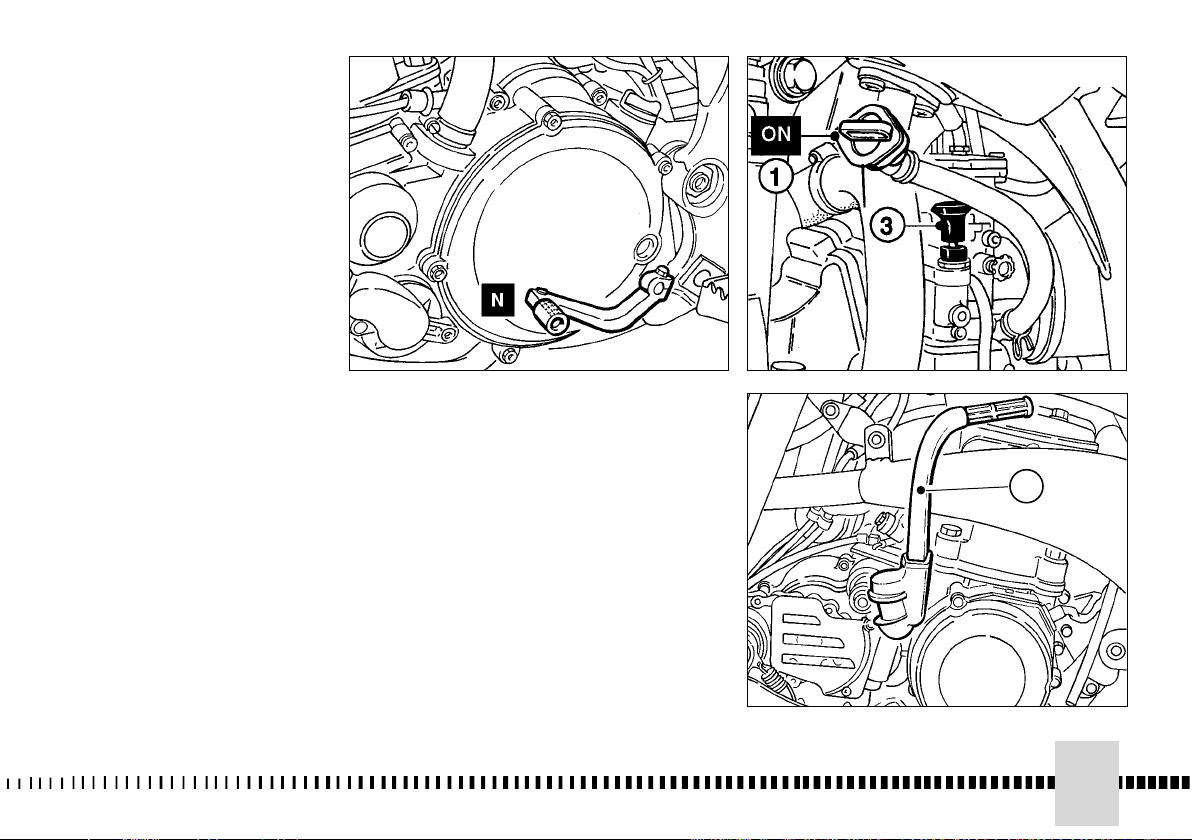
PUESTA EN MARCHA DEL
MOTOR
Para proceder correctamente
al arranque del motor en frío,
haga lo siguiente:
- poner el cambio de marchas en
punto muerto;
- Ponga el grifo del carburante
(1) en posición ON;
alce la palanca del STARTER
(3) en el carburador.
Dejando el pomo de la mariposa
en posición completamente
cerrada, actúe en el pedal (4) de
arranque
Lleve el pomo del starter a la
posición inicial en cuanto el
motor esté en condiciones de
mantener el ralentí. En caso de
arranque en caliente NO utilice el
starter.
El arranque se puede realizar
también con la marcha
engranada previo desembrague.
4
73
Page 74

In caso di ingolfamento del carburatore, chiudere
il rubinetto carburante, lo starter ed agire sul
pedale di avviamento sino a quando il motore
partirà. Se necessario rimuovere la candela ed
asciugarla.
NOTA IMPORTANTE IN CASO DI AVVIAMENTO
A FREDDO A BASSE TEMPERATURE
Si raccomanda di effettuare un breve
riscaldamento al minimo fino a quando, dopo
aver disinserito lo starter, ci sarà una normale
risposta del motore alle aperture del comando
gas.
Questo permetterà al lubrificante di raggiungere
la corretta temperatura di esercizio garantendo
così il corretto funzionamento di tutti gli organi
del motore. Evitare di effettuare un riscaldamento
troppo prolungato del motore.
If the carburetor is flooded, shut off the
fuel supply and the starter and operate
the crank lever or the kick-start until the
engine starts. If necessary,
remove the spark plug and dry it.
IMPORTANT NOTE IN CASE OF COLD
STARTS AT LOW TEMPERATURES
It is recommended to briefly warm-up the
engine at idle until, after having disengaged
the starter, there is a normal response from
the engine when opening the throttle.
This will enable the lubricant to reach the
correct working temperature thereby
guaranteeing a correct functioning of all
engine parts.
En cas de noyage du carburateur, fermer le
robinet d’essence, le démarreur et presser la
pédale de démarrage jusqu’à le moteur
démarre. Si nécessaire, enlever la bougie et
l’essuyer.
N
OTE IMPORTANT DANS LE CAS DE LA MISE
EN ROUTE A’ FROID ET TEMPERATURES BAS
C’est conseiller de effectuer un bref chauffage au
minimum, après avoir débrancher le starter,
lorsque on obtien la normale réponse du moteur
aux ouvertures du gaz.
Ce-ci peut admettre au huile lubrifiante de arriver
à la température d’exercice jusqu’à garantir le
correct fonctionnement de tous les éléments du
moteur. On doit éviter de effectuer un chauffage
trop prolongé du moteur.
ATTENZIONE*: Il sistema di scarico contiene
gas di monossido di carbonio. Non far mai
girare il motore in luoghi chiusi.
ATTENZIONE*: In fase di avviamento di
questo tipo di motociclo ad alte prestazioni si
può verificare, talvolta, un forte
“contraccolpo” . Non avviare il motore senza
aver prima indossato stivali di guida
appropriati, particolarmente protettivi. Si
corre il rischio di ferirsi seriamente alla
gamba nel caso il pedale dia il “contraccolpo”
ed il piede scivoli.
74
WARNING*: Exhaust contains poisonous carbon monoxide gas. Never run
the engine in a closed garage or in a
confined area.
WARNING*: This high performance motorcycle can some times «kick back»
strongly when you are starting it.
Do not attempt to start this motorcycle
unless you are wearing high top heavy
sided riding boots. You could seriously
hurt you leg if the kickstarter kicked
back and your foot slipped.
ATTENTION*: Le système d’échappement
des gaz contient monoxyde de carbone. Il
est donc avis de ne jamais tourner à vide le
moteur dans des milieux fermés.
ATTENTION*: Durant la phase de
démarrage moteur de ce type de motocycle
à haute performance, un fort “choc en
retour” pourrait se produire. Ne jamais
démarrer le moteur sans avoir mis les
bottes de protection, car on court le risque
de blesser la jambe si la pédale donne un
fort “choc en retour”, et le pied glisse.
Page 75

Sollte der Vergaser überschwemmt sein, sind
Kraftstoffhahn und Starter zu schliessen und auf
den Kickstarter einzuwirken, bis der Motor in
Betrieb gesetzt wird. Wenn notwendig, Kerze
herausnehmen und sie reinigen.
En caso de ahogo del carburador, cierre el grifo
del carburante, el starter y apriete el pedal de
arranque hasta que el motor se ponga en
marcha. Si fuera necesario, remueva la bujía y
séquela.
Starter zu kaltem des Motors in Anwesenheit
ES BEMERKT WICHTIG:
von niedrigen Umwelt Temperaturen
Sie empfiehlt, zu das geringst eine kurze
Erwärmung vorzunehmen bis, es wird eine
normale Antwort des Motors zum Gashebel
geben, nachdem wird es die Vorrichtung des
Starters abgeschaltet haben.
Dieses wird dem flüssigen Kühlmittel erlauben
die richtige Temperatur zu erreichen und
garantieren so das korrekte Funktionieren von
allen Organen des Motors. Sie empfiehlt, nicht
zu viel lange den Motor zu wärmen.
ACHTUNG *: Die Auspuffanlage enthält
Kohlenoxydgas. Niemals den Motor in
geschlossenen Räumen laufen lassen.
ACHTUNG*: In der Anlaufphase dieses
Motorradtyps hoher Leistungen kann
manchmal ein starker “Rückschlag”
auftreten. Den Motor nicht anlassen, ohne
vorher geeignete, besonders geschützte
Fahrstiefel angezogen zu haben. Es besteht
die Gefahr, sich ernsthaft am Bein zu
verletzen, falls das Pedal “zurückschlägt”
und der Fuß abrutscht.
NOTA IMPORTANTE EN CASO DE
ARRANQUE A. FRÍO A. BAJAS
TEMPERATURAS
Se encomienda de efectuar una breve
calefacción a lo mínimo hasta a cuando,
después de haber desconectado el dispositivo
del starter, habrá una normal respuesta del
motor a las aberturas del mando mariposa.
Éste permitirá al lubricante de alcanzar la
correcta temperatura de ejercicio garantizando
así el correcto funcionamiento de todos los
órganos del motor. Evitar efectuar una
calefacción demasiado prolongada del motor.
ATENCIÓN*: La instalación de descarga
contiene gas de monóxido de carbono. No
dejar que el motor gire en lugares cerrados.
ATENCIÓN*: Durante la fase de arranque de
este tipo de motociclo de altas prestaciones,
tal vez puede ocurrir un fuerte “rebote”. No
poner en marcha el motor sin haberse
puesto antes botas adecuadas para
conducir, de grande protección. Hay el
riesgo de herirse seriamente en la pierna en
caso el pedal rebote y el pie se deslice.
75
Page 76

ARRESTO DEL MOTOCICLO
- Chiudere completamente il gas lasciando
innestata la frizione (eccetto quando si
cambia marcia) in modo da far decelerare il
motociclo.
- Frenare sia anteriormente che
posteriormente mentre si scalano le marce.
- Per una forte decelerazione, agire in modo
decisivo su leva e pedale dei freni.
- Una volta arrestato il motociclo,
disinnestare completamente la frizione e
mettere in folle.
STOPPING THE
MOTORCYCLE
- Close the throttle completely leaving the
clutch engaged (except when shifting
gears) so that the engine will help slow
down the motorcycle.
- For normal braking, gradually apply both
front and rear brakes while down shifting.
- For maximum deceleration apply the front
and rear brakes firmly.
- When stopped, fully disengage the clutch
and shift to neutral as necessary to keep
the engine from stalling.
ARRET DU MOTOCYCLE
Fermer la poignée des gaz tout en laissant
l’embrayage inséré (à l’exception d’un
changement de vitesse), de façon à
réduire la vitesse du motocycle.
- Tandis que les vitesses sont réduites,
freiner soit la roue avant, soit l’arrière.
- Pour une forte décélération, appuyer
avec décision sur le levier et sur la pédale
des freins.
- Une fois que le motocycle est arrêté,
débrayer et mettre la moto au point mort.
ATTENZIONE*: In alcune condizioni può
essere utile l’uso indipendente del freno
anteriore o di quello posteriore. Usare il
freno anteriore con prudenza,
specialmente su terreni sdrucciolevoli.
L’uso scorretto dei freni può causare
gravi incidenti.
76
WARNING*: ndependent use of the front
or rear brake maybe advantageous under certan conditions. Use caution
when using the front brake, especially
on slippery surfaces. Improper use of
the brakes can lead to a serious crash.
ATTENTION * : Dans des conditions
particulières, il est avis d’utiliser
independemment le frein avant ou
l’arrière. En roulant sur des terreins
glissants, utiliser prudemment le frein
avant. L’usage incorrect des freins peut
causer des accidents sérieux.
Page 77

MOTORANHALT
- Das Gas vollständig schließen und die
Kupplung eingekuppelt lassen
(ausgenommen beim Gangwechsel)
derart, daß das Motorrad verlangsamt.
- Sowohl vorn als auch hinten beim
Herunterschalten der Gänge bremsen.
- Zur starken Verlangsamung, entschieden
Hebel und Bremspedale betätigen.
- Nach dem Anhalten des Motorrads, die
Kupplung vollständig auskuppeln und in
Leergang stellen.
PARADA DEL MOTOCICLO
Cerrar completamente el gas dejando
embragada la fricción (excepto cuando se
cambia marcha) de manera que el
motociclo decelere.
- Frenar con los frenos delantero y trasero
mientras se reducen las marchas.
- Para obtener una fuerte deceleración,
actuar de manera decidida sobre la
palanca y el pedal de los frenos.
- Una vez parado el motociclo,
desembragar por completo y poner a punto
muerto.
ACHTUNG* : Unter einigen Umständen
kann es nützlich sein, die vordere
Bremse oder die hintere Bremse
unabhängig zu benutzen. Die vordere
Bremse mit Vorsicht benutzen,
besonders auf rutschigen Geländen.
Die unrichtige Anwendung der Bremsen
kann schwere Unfälle verursachen.
ATENCIÓN *: En algunos casos puede
ser útil el uso independiente del freno
delantero o del trasero. Utilizar el freno
delantero con prudencia, sobre todo
sobre terrenos resbaladizo. El uso
incorrecto de los frenos puede causar
graves accidentes.
77
Page 78

ARRESTO MOTORE
G
Porre la leva del cambio in
posizione di folle.
G
Girare la manopola del gas
contro il fermo.
G
Premere il pulsante arresto
motore (1).
G
Chiudere il rubinetto del
carburante.
STOPPING ENGINE
G
Put gear lever in neutral
position.
G
Turn twist grip against stop.
G
Press the engine stop button
(1).
G
Close hand fuel tap.
ARRET MOTEUR
G
Placer le levier de la boîte des
vitesses au point mort.
G
Tourner la poignée des gaz
contre la butée.
G
Presser le bouton d’arrêt
moteur (1).
G
Fermer le robinet d’essence.
MOTORSTILLSTAND
G
Den Schalthebel in
Leerlaufstellung bringen.
G
Den gasgriff gegen den
Anschlag drehen.
G
Den Motoranhalt-Druckknopf
(1) drücken.
G
Den Treibstoffhahn schliessen.
NOTA
Se il rubinetto non chiude il
flusso, il carburatore potrebbe
ingolfarsi lasciando entrare il
carburante nel basamento. Sarà
impossibile, pertanto, avviare il
motore senza aver fatto
fuoriuscire la benzina.
ATTENZIONE*: In caso di
bloccaggio del gas in
posizione aperta o di altro
malfunzionamento che
facesse girare il motore in
modo incontrollabile,
premere IMMEDIATAMENTE il
pulsante arresto motore.
Mantenere il controllo del
motociclo con il normale uso
dei freni e dello sterzo mentre
si preme il pulsante di
arresto.
78
NOTE
If the fuel tap is not tight, the
carburetor could flood, and fuel
will get into the crankcrase. The
engine will be impossible to start
until the fuel is drained out.
WARNING*: In the event of
stuck throttle or other malfunction which causes the
engine to run uncontrollably,
IMMEDIATELY depress the
engine stop button and hold
it down. Control the motorcycle by normal use of the
brakes and steering while
holding the engine stop button down.
AVI S
Si le robinet n’est pas étanche, le
carburateur pourrait se noyer et
l’essence atteindre dans l'mbase.
Il faudra alors éliminer l’essence
pour démarrer le moteur.
ATTENTION * : Au cas d’un
blocage de la poignée des
gaz dans la position ouverte,
ou de tout autre mauvais
fonctionnement où le moteur
tourne d’une façon
incontrôlable, appuyer
IMMEDIATEMENT sur le
bouton d’arrêt moteur.
Tandis que ce bouton est
pressé, garder le contrôle du
motocycle, et utiliser
doucement les freins et le
guidon.
BEMERKUNG
Wenn der Hahn den Fluss nicht
schliesst, kann der Vergaser
ueberschwemmen und Kraftstoff
in den Treibstoff einfliessen
lassen. Es wird daher notwendig
sein, das Benzin abfliessen zu
lassen, bevor den Motor
anzufahren.
ACHTUNG * : Im Falle der
Gassperrung in offener
Position oder anderer
Störung, die den Motor
unkontrollierbar drehen läßt,
SOFORT den MotoranhaltDruckknopf drücken. Die
Kontrolle des Motorrades
unter normaler Benutzung
der Bremsen und der
Lenkung beim Drücken des
Anhalt-Druckknopfes
behalten.
Page 79
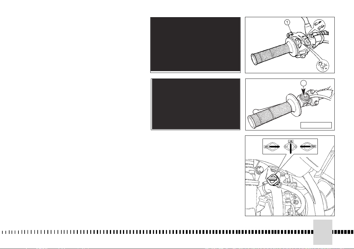
PARADA MOTOR
G
Poner la palanca de cambio en
punto muerto.
G
Girar la palanca del gas contra
el tope.
G
Apretar el pulsador de parada
del motor (1).
G
Cerrar la válvula del
combustible.
NOTA
Si el grifo no cierra el paso, el
carburador podría ahogarse
dejando entrar el carburante en
el motor.
Será imposible, pues, poner en
marcha el motor si antes no se
hace salir la gasolina.
1
ATENCIÓN *: En caso de
bloqueo del gas en la
posición abierta o de otro
funcionamiento incorrecto
que hiciera girar el motor de
manera incontrolable, apretar
INMEDIATAMENTE el
pulsador de parada motor.
Mantener el control del
motociclo con un uso normal
de los frenos y de la
dirección, mientras se aprieta
el pulsador de parada.
USA/CDN
79
Page 80

RODAGGIO
Al fine di ottenere, tra le parti in movimento
del motore, un corretto assestamento che
consenta una ottimale utilizzazione del
motociclo, è necessario eseguire un periodo
di rodaggio di alcune ore secondo le modalità
sottoriportate.
1. Avviare il motore e, DA FERMO, lasciarlo
girare al minimo aprendo e chiudendo il
gas periodicamente sino a quando si sarà
completamente riscaldato. Entro 3-4
minuti, la temperatura del refrigerante avrà
raggiunto ~ 60° C/140° F.
2. Spegnere il motore e lasciarlo raffreddare
naturalmente sino a temperatura ambiente;
questo consentirà il corretto assestamento
del pistone nel cilindro.
3. Ripetere i cicli 1 e 2 sempre DA FERMO.
4. Portare il motore alla normale temperatura
d'esercizio. Guidare il motociclo a velocità
moderata per circa 10 minuti. Ripetere la
procedura di raffreddamento
precedentemente descritta. EVITARE
BRUSCHE ACCELERAZIONI.
5. Portare il motore a temperatura
d'esercizio. Guidare il motociclo per circa
15 minuti passando gradualmente a
velocità più elevate. Evitare sempre
brusche accelerazioni.
6. Ripetere il ciclo di raffreddamento.
7. Anche dopo aver completato il rodaggio,
evitare l'apertura completa del gas sino a
quando il motore non avrà raggiunto la
temperatura d'esercizio.
La corretta osservanza di questa procedura
di rodaggio, incrementerà sensibilmente la
durata e le prestazioni del motore.
RUNNING IN
To obtain the best settling of the engine
moving elements, for driving your
motorcycle to the best of your capability,
run in the engine for several hours,
following these procedures:
1. FROM STOP POSITION. Start the engine
and run at idle, but open the throttle
periodically and briefly until the engine is
thoroughly warmed up. Within 3-4 minutes
the coolant temperature will have reached
approximately 60° C/140° F. (Do not ride
the motorcycle).
2. Stop the engine, and let it cool down
naturally until its temperature is equal to
the ambient air temperature. This will allow
the piston to align itself to any
imperfections which might exist at the
cylinder wall.
3. Repeat steps 1 and 2. (Do not ride the
motorcycle).
4. Bring the engine up to normal running
temperature. Ride the motorcycle
approximately 10 minutes at moderate
speeds. Then repeat cool down procedure.
AVOID HARD ACCELERATIONS.
5. Bring engine up to normal temperature.
Ride motorcycle approximately 15 minutes
at moderate to high speeds. Again avoid
hard accelerations.
6.Repeat cool down procedure.
7. Full throttle operation must be avoided
until the engine has reached operating
temperature, even after the break in
process is completed.
When the above procedure is followed
correctly, engine durability and performance
will be greatly enhanced.
RODAGE
Au but d’obtenir un tassement correct des
éléments rotatifs moteur pour une correcte
utilisation du motocicle, il faudra roder le
moteur pour quelques heures, selon les
instructions données ci-dessous.
1. Démarrer le moteur, EN POSITION
D'ARRET, laissez-le tourner au minimum en
ouvrant et fermant les gaz périodiquement
jusq'à ce qu'il soit chaud. En 3 ou 4 minutes,
la température du liquide réfrigérant aura
atteint environ ~ 60° C/140° F.
2. Arrêter le moteur et le laisser refroidir
naturellement jusqu'à température ambiante.
Ceci pour un ajustement du piston dans le
cylindre.
3. Répéter les cycles 1 et 2 toujours A
L'ARRET.
4. Porter le moteur à température normale de
fonctionnement. Conduire la motocyclette à
une vitesse modérée pendant environ 10
mm. Répéter la procédure de refroidissement
d'ecrite précédemment. EVITER LES
ACCELERATIONS BRUSQUES.
5. Porter le moteur à température de
fonctionnement. Conduire la motocyclette
pendant environ 15 mm en passant
progressivement à des vitesses plus élevées.
Eviter les accélérations brusques.
6. Répéter le cycle de refroidissement.
7. Même une fois le rodage effectué, éviter
l'ouverture complète des gaz tant que le
moteur n'a pas atteint sa température de
fonctionnement.
L'observation correcte de cette procédure de
rodage augmentera sensiblement la durée et la
prestation du moteur.
80
Page 81

EINFAHREN
Zur Erhaltung eines richtigen Einlaufs
zwischen den beweglichen Motorteilen,
welcher eine optimale Benutzung des
Motorrads gestattet, ist es erforderlich, eine
Einfahrzeit von einigen Stunden
entsprechend der unten angegebenen Weise
durchzuführen.
1. Den Motor anlassen und ih, BEI STILLSTAND
so niedrig wie möglich laufen lassen, indem
man das Gas periodisch zuführt oder sperrt,
bis er sich komplett erwärmt hat. Innerhalb von
3-4 Minuten wird die Temperatur des
Kühlmittels ~ 60° C/140° F. erreicht haben.
2. Den Motor ausschalten und ihn sich auf
natürliche Art bis zu Raumtemperatur
abkühlen lassen: das wird die korrekte
Lagerung des Kolbens im Zylinder
ermöglichen.
3. Die Zyklen 1 und 2 immer BEI STILLSTAND
wiederholen.
4.Den Motor auf die normale Betriebstemperatur
bringen. Das Motorrad bei mässiger
Geschwindigkeit etwa 10 Minuten fahren. Die
vorher beschriebene Kühlungsprozedur
wiederholen. ABRUPTE
BESCHLEUNIGUNGEN VERMEIDEN.
5. Den Motor auf Betriebstemperatur bringen.
Das Motorrad etwa 15 Minuten fahren, indem
man stufenweise zu höheren
Geschwindigkeiten übergeht. Immer abrupte
Beschleunigungen vermeiden.
6.Den Kühlungszyklus wiederholen.
7. Auch nach dem Abschluss des Einfahrens die
komplette öffnung des Gases vermeiden bis
der Motor die Betriebstemperatur erreicht hat.
Die korrekte Einhaltung dieser Einfahrprozedur
wird die Dauer und die Leistungen des Motors
merklich erhöhen.
RODAJE
Al fin de alcanzar un correcto ajuste entre las
parte del motor en movimiento y permitir un
uso optimal del motociclo, es necesario
efectuar un período de rodaje de algunas
horas según las indicaciones de abajo.
1. Accionar el motor y SIN MOVERSE dejarlo
girar al mínimo abriendo y cerrando el
acelerador periódicamente hasta cuando se
haya calentado completamente. Luego de 3-4
minutos la temperatura del refrigerante habrá
alcanzado 60° C/140° F. aprox.
2. Apagar el motor dejarlo enfriar naturalmente
hasta la temperatura ambiente; esto
consentirá el correcto asentamiento del pistón
en el cilindro.
3. Repetir los ciclos 1 y 2 siempre con la
MOTOCICLETA DETENIDA
4. Llevar el motor a la temperatura normal de
ejercicio. Manejar la motocicleta durante10
minutos a velocidad moderada.
Repetir la operación de enfriamiento
anteriormente describida. EVITAR BRUSCAS
ACELERACIONES.
5. Calentar el motor hasta alcanzar la
temperatura de ejercicio. Manejar la
motocicleta por aproximadamente 15 minutos
acelerando gradualmente. Evitar siempre
bruscas aceleraciones.
6. Repetir el ciclo de enfriamiento.
7. También luego de haber completado el rodaje,
evitar la apertura completa del gas hasta que
el motor no habrá alcanzado la temperatura de
ejercicio.
La correcta realización de este procedimiento de
rodaje, incrementará sensiblemente la duración y
las prestaciones del motor.
81
Page 82

CONTROLLI DURANTE IL RODAGGIO
Le verifiche da effettuare durante il rodaggio
sono le seguenti:
- CONTROLLO TENSIONE RAGGI RUOTE
(172);
- CONTROLLO SERRAGGIO RUOTE -
- CONTROLLO SERRAGGIO PERNO
FORCELLONE
- CONTROLLO REGOLAZIONE CATENA
(vedi pag. 128);
- CONTROLLO GIOCO CUSCINETTI DI
STERZO (vedi pag. 102);
- CONTROLLO SERRAGGIO MANUBRIO
- CONTROLLO SERRAGGIO MOTORE AL
TELAIO
- CONTROLLO SERRAGGIO RACCORDO
ASPIRAZIONE
- CONTROLLO SERRAGGIO DADI TESTA
E CILINDRO
CHECKS WHILE RUNNING IN
When running in, the following should be
checked out:
- WHEELS SPOKES TENSION (172);
- TIGHTENING OF WHEELS
- FORK PIN TIGHTENING
- CHAIN ADJUSTMENT (see page 128);
- STEERING BEARING PLAY (see page
102);
- HANDLEBAR TIGHTENING
- ENGINE GRIP TO FRAME
- SUCTION FITTING GRIP
- HEAD AND CYLINDER NUTS GRIP
CONTROLES PENDANT LE RODAGE
Les contrôles à effectuer pendant le rodage
sont les suivants:
- CONTROLE DE LA TENSION DES
RAYONS DES ROUES (172);
- CONTROLE DU SERRAGE ROUES
- CONTROLE DU SERRAGE GOUPILLE
FOURCHE
- CONTROLE DU REGLAGE CHAINE (se
reporter à la page 128);
- CONTROLE DU JEU DES ROULEMENTS
DE LA DIRECTION (se reporter à la page 102);
- CONTROLE DU SERRAGE DU GUIDON
- CONTROLE DU SERRAGE DU MOTEUR
SUR LE CADRE
- CONTROLE DU SERRAGE DU RACCORD
D'ASPIRATION
- CONTROLE DU SERRAGE ECROUS,
TETE ET CYLINDRE
Nota*: Terminato il rodaggio, montare una
nuova candela e sostituire l’olio del
cambio.
82
Note*: After break in, install a new spark
plug and change the transmission oil.
Nota*: Une fois le rodage terminé,
monter une nouvelle bougie et effectuer
une vidange de l’huile de la boîte des
vitesses.
Page 83

KONTROLLEN WÄHREND
DES EINFAHRENS
Folgende Nachprüfungen müssen während
des Einfahrens durchgeführt werden.
- KONTROLLE SPANNUNG RADSPEICHEN
(172);
CONTROLES DURANTE EL RODAJE
Los controles que se deben efectuar durante
el rodaje son los siguientes:
- CONTROL TENSION RADIOS RUEDAS
(173) ;
- CONTROL AJUSTE RUEDAS
- KONTROLLE RADVERSCHRAUBUNG
- KONTROLLE VERSCHRAUBUNG DER
GROSSEN GABEL
- KONTROLLE KETTENEINSTELLUNG
(siehe Seite 128);
- KONTROLLE SPIEL LENKERLAGER
(siehe Seite 102);
- KONTROLLE LENKERVERSCHRAUBUNG
- KONTROLLE VERSCHRAUBUNG MOTOR
AM RAHMEN
- KONTROLLE VERSCHRAUBUNG
ANSAUGEVERBINDUNGSSTÜCK
- KONTROLLE VERSCHRAUBUNG
MUTTERN KOPF UND ZYLINDER
Bemerkung*: Nach Ablauf der
Einfahrzeit eine neue Zündkerze
einsetzen und das Getriebeöl wechseln.
- CONTROL AJUSTE PERNO HORQUILLA
- CONTROL REGULACION CADENA
(ver pag. 129);
- CONTROL JUEGO COJINETES DE
DIRECCION (ver pag. 103);
- CONTROL AJUSTE MANILLAR
- CONTROL AJUSTE MOTOR AL CHASIS
- CONTROL AJUSTE CONEXION
ASPIRACION
- CONTROL AJUSTE TUERCAS CABEZA Y
CILINDRO
Nota*: Al terminar el rodaje, montar una
bujía nueva y sustituir el aceite del
cambio.
83
Page 84

CONTROLLO LIVELLO OLIO
CAMBIO
Tenendo il motociclo in piano ed in
posizione verticale, rimuovere la
vite (C) di controllo e verificare il
livello attraverso il foro di
quest’ultima.
TRANSMISSION OIL LEVEL
CHECKING
By keeping the motorcycle on a
flat surface and in vertical
position, remove the control
screw (C), and check the level
through the hole in the screw.
CONTROLE DU NIVEAU D'HUILE
DU BOITE DE VITESSE
Garder la moto à plat et dans la
position verticale; ôter la vis de
contrôle (C) et contrôler le
niveau par le trou se trouvant
sur la vis.
KONTROLLE OLPEGEL
WECHSELGETRIEBE
Das Motorrad flach und in
.
vertikaler Position aufstellen,
die Kontrollschraube ( C )
entfernen und den Stand durch
das Schraubenloch überprüfen.
Nota*: Eseguire questa
operazione a motore caldo.
A Tappo di scarico
B Tappo immissione
C Vite controllo livello
84
Note*: Have this operation
made with warmed-up engine.
A Draining plug
B Filling cap
C Levelling screw
Avis*: effectuer cette opération à
moteur chaud.
A Bouchon de décharge
B Bouchon introduction
C Vis de contrôle niveau
Bemerkung*: Diese Arbeit nur
Motor vernehmn.
A Ablasstopfen
B Einfullstopfen
C Standkontrollschraube
Page 85
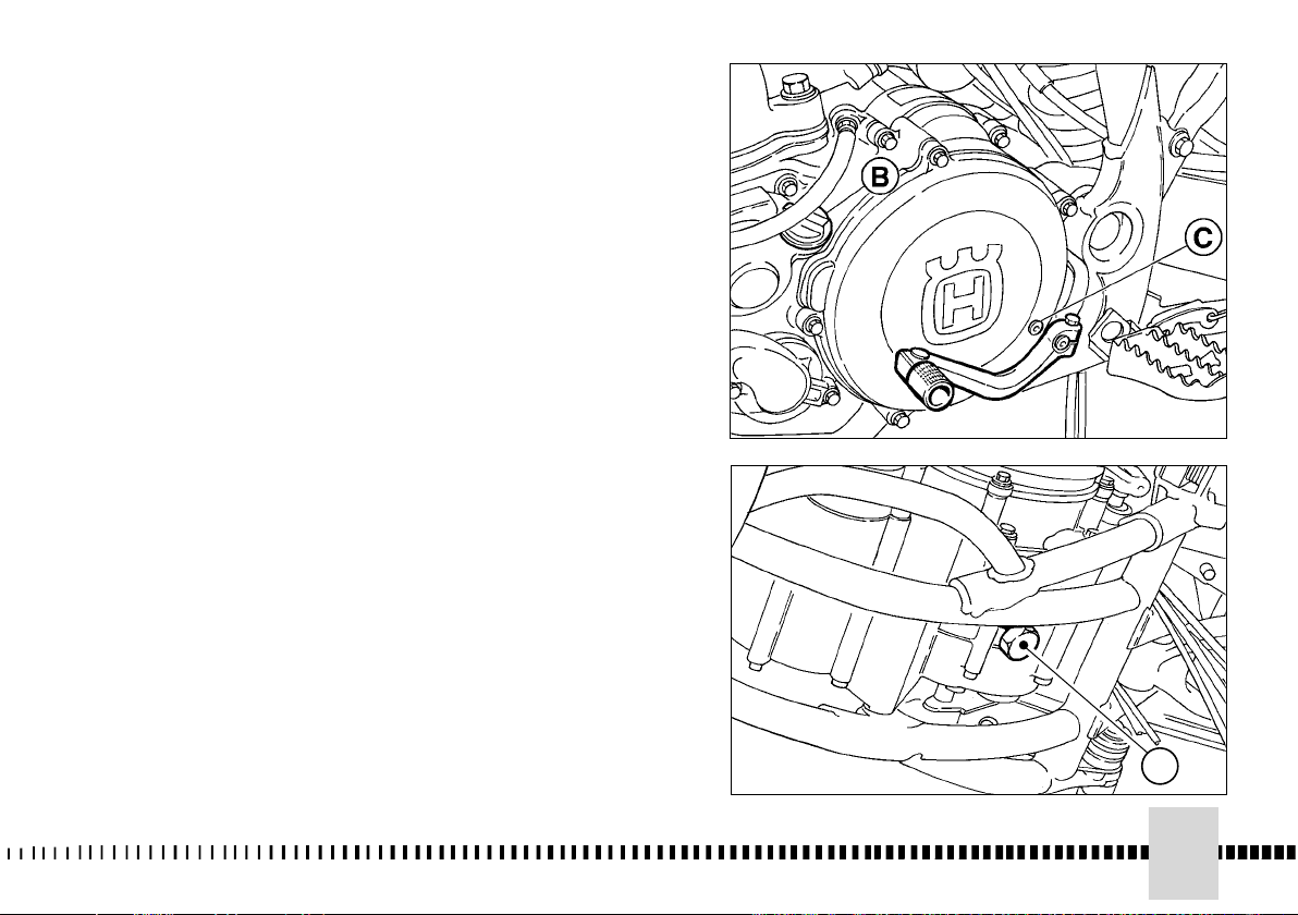
CONTROL NIVEL ACEITE DEL
CAMBIO
Manteniendo el motociclo en
plano y en posición vertical,
remover el tornillo (C) de
control y averiguar el nivel a
través del agujero que tiene el
tornillo mismo.
Notas*: Realice esta operación
con el motor caliente.
A Tapon de salida
B Tapon entrada
C Tornillo control nivel
85
A
Page 86

SOSTITUZIONE OLIO CAMBIO
Per sostituire completamente
l'olio, svitare il tappo (A)
sottocoppa e lasciare defluire
completamente l'olio; quindi
riavvitare il tappo con relativa
guarnizione e versare l'olio fresco
dal foro del tappo di carica.
Impiegare sempre olio nella
quantità e del tipo prescritto
(vedere a pagina 34, 36).
TRANSMISSION OIL CHANGE
To completely replace the oil,
unscrew the plug (A) under the
oil sump and let oil come out,
then screw the plug again with its
gasket and pour fresh oil from
the hole of the loading plug.
Use only the prescribed quantity
and type of oil (see on page
34,36).
VIDANGE D'HUILE BOITE DE
VITESSE
Pour remplacer complètement
l'huile, dévisser le bouchon (A) se
trouvant au dessous de la cuve
de l'huile et laisser couler complètement l'huile, enfin visser le
bouchon à nouveau avec sa
garniture et remplir avec de
l'huile nouvelle au moyen du trou
du bouchon de chargement.
Utiliser seulement la quantité et
le type d'huile indiqués (voir à la
page
34,36
).
ERSETZUNG ÖL
WECHSELGETRIEBE
Um das Öl zu ersetzen wird man
de Stöpsel (A) under der Wanne
abschrauben und das Öl ganz
ausfliessen; dann den Stöpsel
mit Dichtung wieder
anschrauben und neues Öl durch
den Nachfüllpropfen giessen.
Oel in der vorgesehenen Menge
und der empfohlenen Marke
verwenden (siehe Seite 35,37).
Nota*:
Eseguire questa operazione a
motore caldo.
A Tappo di scarico
86
Note*:
Have this operation made with
warmed-up engine.
A Draining plug
Avis*:
Attention: effectuer cette
opération à moteur chaud.
A Bouchon de decharge
Bemerkung*:
Diese Arbeit nur bei warmem
Motor vernehmen.
A Ablasstopfen
Page 87
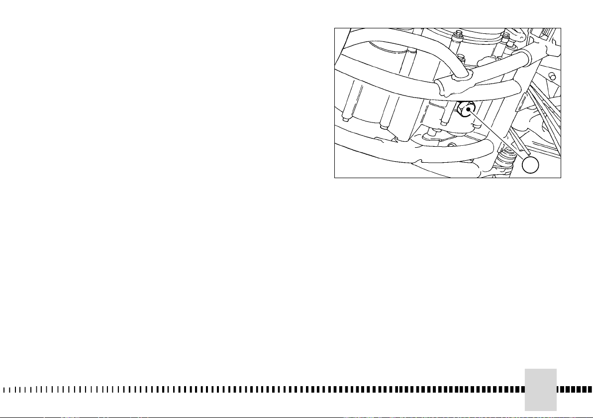
SUBSTITUCION ACEITE DEL
CAMBIO
Para substituir completamente el
aceite, destornille el tapón (A)
debajo del cárter y haga salir
completamente el aceite; luego
vuelva a atornillar el tapón con su
correspondiente guarnición y
vierta el aceite fresco por el
orificio del tapón de carga.
Emplee siempre aceite en
cantidad y tipo prescripto (véase
pág. 35,37).
Notas*:
Realice esta operación con el
motor caliente.
A Tapon de salida
A
87
Page 88

CONTROLLO LIVELLO LIQUIDO DI
RAFFREDDAMENTO
Controllare il livello (A) nel radiatore destro
a motore freddo e con il motociclo in
posizione verticale. Il refrigerante deve
trovarsi 10 mm. sopra gli elementi
AVVERTENZA
Non togliere il tappo del radiatore a
motore caldo. Si corre il rischio che il
liquido fuoriesca e provochi ustioni.
NOTA
Potrebbero sorgere difficoltà
nell'eliminare il liquido da superfici
verniciate. Se così fosse, lavare con
acqua.
SOSTITUZIONE LIQUIDO DI
RAFFREDDAMENTO
Il rifornimento del liquido di raffreddamento
si effettua dal tappo di carico del radiatore;
per la quantità da introdurre vedere a pag.
30. Per lo scarico occorre rimuovere:
a) il coperchio pompa svitando le due viti
(1) di fissaggio, oppure
b) la vite di scarico (2) sul coperchio
pompa.
Lasciar drenare completamente il liquido.
Rimontare il coperchio pompa o la vite
precedentemente rimossi.
ATTENZIONE*: Il refrigerante sui
pneumatici li renderà sdrucciolevoli con
potenziali rischi di incidenti o lesioni.
Controllare periodicamente i manicotti di
collegamento (vedi “Scheda di
manutenzione periodica”); ciò eviterà che si
verifichino perdite di refrigerante con
conseguente rischio di grippaggio del
motore. Se sulle tubazioni si presentano
screpolature, rigonfiamenti o indurimenti
dovuti ad essiccamento dei manicotti, sarà
opportuna la loro sostituzione.
Controllare il corretto fissaggio delle
fascette.
COOLANT LEVEL CHECK
Check level (A) in right-hand radiator
when engine is cold (place the
motorcycle so that it is perpendicular to
the ground). The coolant should be
approximately 10 mm above cells.
WARNING
Avoid removing radiator cap when
engine is hot, as coolant may spout
out and cause scalding.
NOTE
Difficulties may arise in eliminating
coolant from varnished surfaces. If
this occurs, wash off with water.
REPLACEMENT OF
COOLING FLUID
The filling of cooling fluid is carried out
through the radiator cap; about the fluid
quantity to be filled, see page 30.
For draining, a) remove the pump cover
by loosening the two screws (1), or:
b) the draining screw (2) set on the
pump cover.
Let the fluid drain fully, then reassemble
the pump cover or the screw previously
removed.
WARNING*: Coolant on tires will
make them slippery and can cause
an accident or injury.
Periodically check the connecting hoses
(see “Periodical maintenance card”):
this will avoid coolant leakages and
consequent engine seizure: If hoses
show cracks, swelling or hardenings
due to sheats desiccation, their
replacement shall be advisable.
Check the correct tightening of the
clamps.
CONTROLE DU NIVEAU REFRIGERANT
Contrôler le niveau (A) dans le radiateur
droit avec moteur arrêté et motocycle en
position verticale. Le réfrigérant doit se
trouver à 10 mm. au dessus des éléments.
ATTENTION
Ne jamais enlever le bouchon du
radiateur avec moteur chaud, car le
liquide pourrait se déverser et provoquer
des brûlures.
AVIS
Si des difficultés surgissent pour enlever
le liquide des éléments laqués, laver à
l’eau.
SUBSTITUTION DU LIQUIDE DE
REFROIDISSEMENT
Le remplissage du liquide de
refroidissement se réalise par le bouchon de
chargement du radiateur; pour la quantité
de remplissage, voir à la page 30.
Éléments à ôter pour la vidange:
a) le couvercle pompe: desserrer les deux
vis de fixation (1), ou:
b) la vis de vidange (2) située sur le
couvercle pompe.
Laisser couler complètement le liquide.
Remonter le couvercle pompe ou la vis
précedemment ôtée.
ATTENTION * : Le fluide réfrigérant sur
les pneus pourrait provoquer des
glissements de la roue et donc, des
accidents sérieux.
Vérifier souvent les manchons
d’assemblage (voir " Fiche d’entretien
périodique "): cela evitera des pertes du
refrigerantet donc des grippages du moteur.
Si sur les tuyanteries il y a des crevasses,
des foisennements ou des durcissements
causés par séchage des manchons, il sera
nécessaire les remplacer.
Contrôler la fixation correcte des colliers.
KONTROLLE PEGEL KÜHLFLÜSSIGKEIT
Den Stand (A) im rechten Kühler bei
stillstehendem Motor und mit Motorrad in
vertikaler Position überprüfen. Das Kühlmittel
muss sich 10 mm über den Elementen befinden.
MAN BEACHTE
Den Stöpsel des Kühlers nicht bei warmem
Motor entfernen. Man läuft Gefahr, dass die
Flüssigkeit ausfliesst und Verbrennungen
verursacht.
ANMERKUNG
Bei der Entfernung der Flüssigkeit von
lackierten Oberflächen könnten
Schwierigkeiten entstehen. Wenn das so ist,
mit Wasser abwaschen.
AUSTAUSCH KÜHLFTÜSSIGKEIT
Das Auffüllen der Kühlflüssigkeit erfolgt durch
Einfüllstopfen des Kühlers. Wegen der
einzufüllenden Menge siehe auf Seite 31.
Zum Ablaß muß abgenommen werden :
a) der Pumpendeckel durch Lösen der beiden
Befestigungsschrauben (1), oder :
b) die Ablaßschraube (2) auf dem
Pumpendeckel.
Die Flüßigkeit vollständig entleeren. Den
Pumpendeckel oder die vorher entfernten
Schrauben wieder anbringen.
ACHTUNG * : Kühlmittel auf den Reifen läßt
diese rutschen mit erheblichen Unfall- oder
Verletzungsgefahren.
Die Verbindungsmuffen von Zeit zu Zeit
nachprüfen (siehe „Karte der periodischen
Wartung“): um Wasserleck und Motorfressen zu
vermeiden. Falls Rissigkeiten, Verhärtung,
Schwellung wegen Muffenaustrocknung an den
Schläuchen vorhanden sind, dann sind, die
Letzten auszuwechseln.
Die Korrekte Befestigung der Schellen
kontrollieren.
88
Page 89
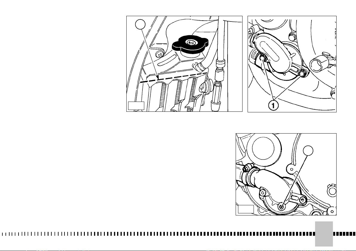
CONTROL NIVEL LIQUIDO
DE ENFRIAMIENTO
Controlar el nivel (A) en el radiador derecho
con el motor parado con el motociclo en
posición vertical.
El refrigerante se debe encontrar a 10 mm por
encima de las piezas.
ADVERTENCIA
No quite el tapón del radiador con el motor
caliente. Se corre el riesgo de que el
líquido salga y produzca quemaduras.
NOTA
Pueden surgir dificultades al eliminar el
líquido de superficies pintadas. Si
ocurriera así, lave con agua.
SUBSTITUCION LIQUIDO DE
ENFRIAMIENTO
El relleno del líquido de enfriamiento se
efectúa por el tapón de carga del radiador;
para la cantidad a verter, véase pág. 31.
Para efectuar el vaciado hay que remover:
a) la tapa bomba desenroscando los dos
tornillos (1) de fijación, o
b) el tornillo de vaciado (2) en la tapa bomba.
Dejar salir completamente el líquido.
Remontar la tapa bomba o el tornillo
precedentemente removidos.
ATENCIÓN *: El refrigerante sobre los
neumáticos los volverá resbaladizos con
riesgos potenciales de accidentes o
lesiones.
Controre periódicamente los manguitos de
conexión (ver “Ficha de mantenimento
periódico): esto evitare pérdidas de agua y por
tanto agarrotamientos del motor. Si en los
tubos se presentaran grietas, hinchazones o
endurecimientos debidos a que los manguitos
están resecos, es conveniente subtituirlos.
Controlar el correcto fijado de los
abrazaderas.
A
a
2
b
89
Page 90

REGOLAZIONE CAVO
COMANDO GAS
La regolazione del cavo
comando gas si può effettuare
tramite il registro posto sul
comando stesso oppure su
quello che si trova sul coperchio
del carburatore. Per verificare la
corretta registrazione del cavo
comando gas operare nel modo
seguente:
- rimuovere il cappuccio in
gomma;
- spostando avanti e indietro la
guaina della trasmissione si
deve riscontrare un gioco di
circa 1 mm;
- nel caso questo gioco risultasse
superiore, sbloccare il
controdado (1) e svitare il
registro (2); agire inversamente
nel caso il gioco fosse inferiore
a 1 mm;
- se la lunghezza del registro (2)
non fosse sufficiente a ottenere
la corretta regolazione, agire sul
registro posizionato sul
carburatore.
Anche su quest'ultimo si deve
riscontrare un gioco di circa 1
mm; in caso contrario, svitare o
avvitare il registro (2) per
diminuire o aumentare detto
gioco dopo aver allentato il
controdado (1).
ATTENZIONE*: Utilizzare il
veicolo con il cavo comando
gas danneggiato pregiudica
notevolmente la sicurezza di
guida.
THROTTLE CABLE
ADJUSTMENT
The throttle cable can be
adjusted using the screw set on
the throttle, or using the
adjusting screw set on the
carburettor cover.
To check for
proper adjustment of throttle
cable, proceed as follows:
- remove rubber cap;
- move transmission sheath to
and fro to ensure a play of
approx. 1 mm;
- should play be greater than 1
mm, loosen lock nut (1) and
register (2); should play less
than 1 mm, then tighten lock
nut and register;
- if register (2) should not provide
sufficient movement to allow for
correct adjustment, then adjust
register placed on carburetor.
There should be approx. 1 mm
play on latter register; should this
not be the case, then
loosen
lock nut (1), and loosen or
tighten screw (2), to
respectively increase or
decrease the play.
WARNING*: Operation with
damaged throttle cable could
result in an unsafe riding
condition.
REGLAGE DU CABLE DE
COMMANDE DES GAZ
Le réglage du câble de
commande gaz s’obtient par la
vis de réglage placée sur la
commande, ou sur la vis se
trouvant sur le couvercle
carburateur.
réglage du câble, opérer comme
suit:
- enlever le capuchon en gomme;
- en faisant aller et venir la gaine
du câble de transmission,
contrôler que le jeu soit 1 mm
environ;
- en présence d’un jeu supérieur,
débloquer la contre-bague (1)
et desserrer la vis de réglage
(2). Agir inversement si le jeu
est inférieur.
- lorsque la longueur de la vis de
réglage (2) ne permet pas
d’obtenir un réglage correct,
agir sur la vis de réglage placée
sur le carburateur.
Pour cette vis aussi le jeu doit
être de 1 mm;
desserré le contre-écrou (1),
desserrer o serrer la vis de
réglage (2), respectivement
pour augmenter ou pour
diminuer le jeu.
ATTENTION: Pour ne pas
porter préjudice à la sécurité,
ne jamais conduire avec le
câble de commande des gaz
endommagé.
Pour le contrôle du
après avoir
EINSTELLUNG DES
GASSEILZUGS
Die Einstellung des Gaskabels
kann mit dem Register auf der
Schaltung selbst oder mit dem
Register auf dem Vergaserdeckel
durchgeführt werden.
Zu Kontrolle
der korrekten Einstellung des
Gasseilzugs gehe man wie folgt vor:
- die Gummikappe entfernen;
- beim Verschieben des
Drehgriffmantels nach vorne und
nach hinten, sollte ein Spiel von
etwa 1 mm feststellbar sein;
- falls das Spiel hoeher sein sollte,
die Gegennutmutter (1) loesen
und den Regler (2) aufschrauben;
im umgekehrten Sinne verfahren,
falls das Spiel weniger als 1 mm
betraegt;
- falls die Laenge des Reglers (2)
fuer eine fachgerechte Einstellung
nicht ausreicht, auf den Regler
wirken, der sich auf dem Vergaser
befindet.
Bei diesem Regler sollte ebenfalls
ein Spiel von etwa 1 mm feststellbar
sein; falls nicht, den Regler auf-oder
festschrauben um das Spiel zu
verringern
das Register (2) zur
Verringerung oder Erhöhung des
Spiels nach vorheriger Lockerung
der Gegenmutter (1) auf- oder
zuschrauben.
ACHTUNG * : Die Auspuffgase
enthalten Kohlenoxyd. Den
Motor nicht in geschlossenen
Räumen laufen lassen.
90
Page 91
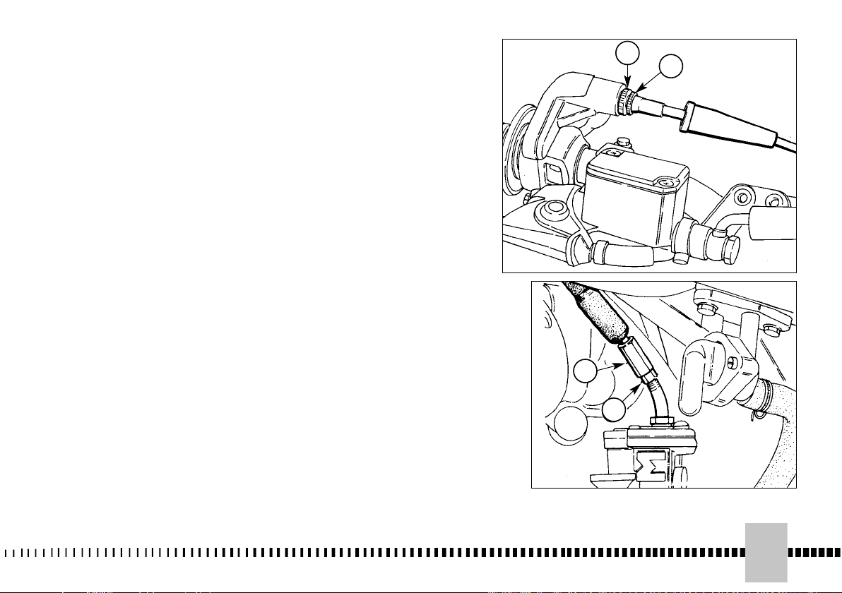
REGULACION CABLE
MANDO MARIPOSA
La regulación del cable del
mando del gas se puede efectuar
a través del ajuste situado en el
mando mismo o del que se halla
sobre la tapa del carburador.
Para comprobar que el cable de
mando de la mariposa esté bien
regulado, haga lo siguiente:
- remueva el capuchón de goma;
- moviendo adelante y atrás la
funda de la transmisión se debe
encontrar un juego de 1 mm
aproximadamente;
- en el caso de que este juego
fuera superior, desbloquee la
contratuerca (1) y destornille el
regulador (2); actúe inversamente
en el caso de que el juego sea
inferior a 1 mm;
- si la longitud del regulador (2) no
fuera suficiente para obtener una
regulación correcta, actúe en el
regulador posicionado en el
carburador.
También en éste se debe encontrar
un juego de 1 mm
aproximadamente; en caso
contrario, destornille o atornille el
regulador
el regulador (2) para disminuir o
aumentar dicho juego tras haber
aflojado la contratuerca (1).
ATENCIÓN * : Los gases de
descarga contienen monóxido
de carbono. No dejar que el
motor gire en lugares cerrados.
enroscar o desenroscar
1
2
2
1
91
Page 92

REGISTRAZIONE MINIMO
La registrazione del minimo deve
essere effettuata solo a motore
caldo e con il comando gas in
posizione chiusa agendo nel
modo seguente:
- girare le vite di registro minimo
(1) sino ad ottenere un regime
del motore piuttosto elevato
(girare in senso orario per
aumentare il regime, in senso
antiorario per diminuirlo);
- girare la vite di registro del titolo
della miscela (2) in senso orario
o antiorario sino a quando il
motore girerà il più
regolarmente possibile;
- svitare progressivamente la vite
(1) sino ad ottenere il minimo
più appropriato.
IDLING ADJUSTMENT
Idling should be adjusted only
when the engine is hot and
throttle is closed, as follows:
- turn idle adjusting screw (1) so
as to increase rpm (turn
clockwise to increase rpms,
counterclockwise to decrease
rpm);
- turn fuel mixture adjusting
screw (2) clockwise or
anticlockwise until engine runs
smoothly;
- gradually loosen screw (1) to
ensure that engine runs
properly.
REGLAGE DU RALENTI
Effectuer ce réglage avec moteur
chaud et commande des gaz en
position fermée, en opérant
comme suit:
- tourner en sens horaire la vis de
réglage du ralenti (1) pour
élever le régime du moteur; la
tourner en sens antihoraire pour
le baisser;
- tourner en sens horaire (ou
antihoraire) la vis de réglage du
mélange (2) jusqu’à ce que la
marche du moteur est la plus
régulière possible;
- desserrer progressivement la
vis (1) pour obtenir un ralenti
correct.
EINSTELLUNG
DREHZAHLMINIMUM
Die Einstellung des
Drehzahlminimums darf nur bei
warmem Motor und mit dem
Gasanlasser in geschlossener
Stellung erfolgen, indem man
folgendermassen vorgeht:
- die Schraube zur Einstellung (1)
des Drehzahlminimums drehen
bis man einen ziemlich hohen
Lauf des Motors erreicht (in
Uhrzeigersinn drehen, um den
Lauf zu erhöhen, entgegen
Uhrzeigersinn, um ihn
herabzusetzen);
- die Einstellschraube für den
Feingehalt der Mischung (2) in
Uhrzeigersinn oder entgegen
Uhrzeigersinn drehen, bis der
Motor so regelmässig wie
möglich läuft;
- die Schraube (1) progressiv
losschrauben bis man das
geeignetste Drehzahlminimum
erreicht.
ATTENZIONE*: I gas di scarico
contengono monossido di
carbonio. Non far girare il
motore in luoghi chiusi.
92
WARNING*: Exhaust gas
contains poisonous carbon
monoxide gas. Never run the
engine in a closed area or in a
confined area.
ATTENTION * : Puisque les
gaz d’échappement contiennent monoxyde de carbone, il
est avis de ne jamais tourner
à vide le moteur dans des
milieux fermés.
ACHTUNG * : Das Fahrzeug
mit beschädigtem
Gasschaltungskabel zu
benutzen beeinträchtigt die
Fahrsicherheit bemerkenswert.
Page 93
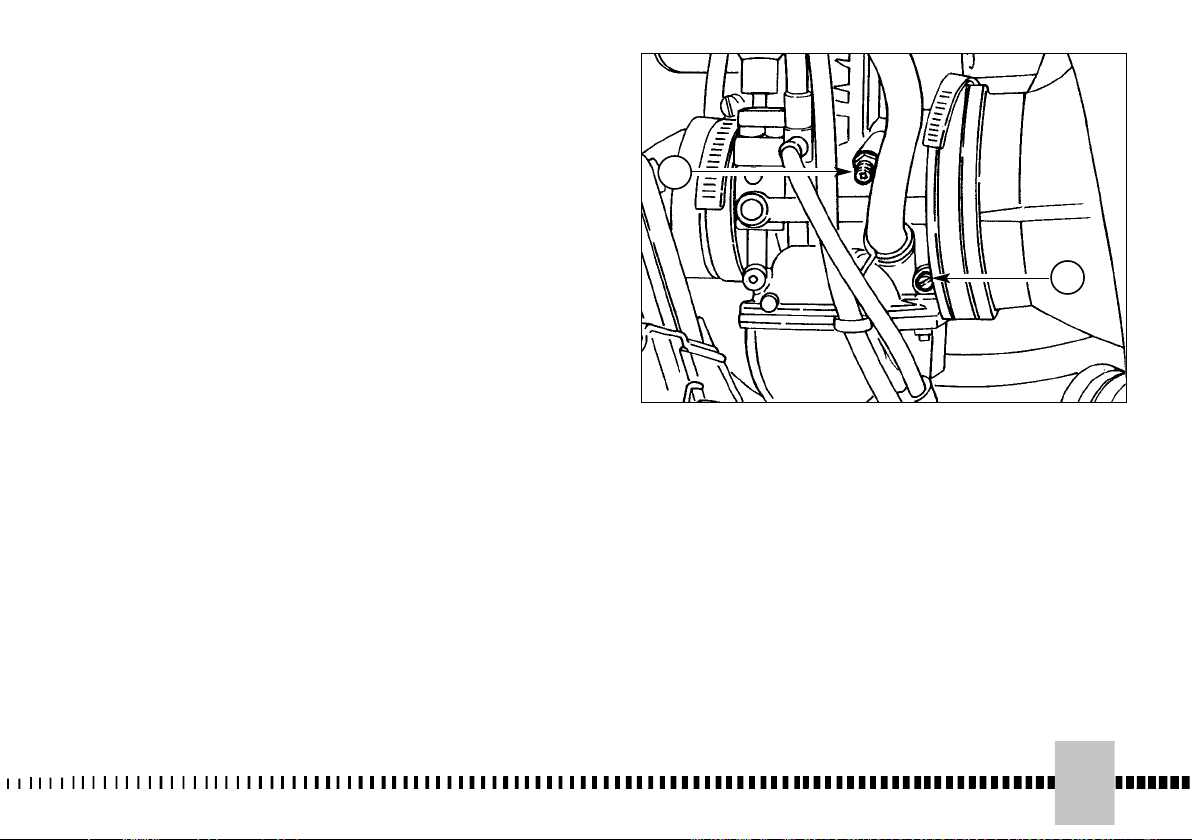
REGULACION RALENTI
La regulación del ralentí debe ser
efectuada sólo con el motor
caliente y con el mando de la
mariposa en posición cerrada
actuando de la siguiente manera:
- gire el tornillo de regulación del
ralentí (1) hasta obtener un
régimen del motor más bien
elevado (gire en el sentido de
las manecillas del reloj para
aumentar el régimen, en
sentido contrario a las
manecillas del reloj para
disminuirlo);
- gire el tornillo de regulación de
la mezcla (2) en el sentido de
las manecillas del reloj o en el
contrario hasta que el motor
gire lo más regular posible;
- destornille paulatinamente el
tornillo (1) hasta obtener el
ralentí más adecuado.
1
2
ATENCIÓN *: Utilizar el
vehículo con el cable mando
gas dañado perjudica
notablemente la seguridad en
la conducción.
93
Page 94

REGISTRAZIONE FRIZIONE
La frizione non richiede,
normalmente, altra regolazione
che quella della tensione del
cavo utilizzando il gruppo di
registro posto sul manubrio.
Generalmente, é sufficiente agire
sul registro posto sul manubrio
per recuperare il gioco dovuto
all’allungamento della
trasmissione flessibile.
La leva di comando deve sempre
avere una corsa a vuoto C (circa
3 mm) prima di iniziare il
disinnesto della frizione. Per
regolare questo gioco, agire sul
registo 2 dopo aver sfilato il
cappuccio in gomma 1; ruotando
il registro nel senso indicato dalla
freccia A si riduce il gioco C
mentre ruotandolo nel senso
indicato dalla freccia B si
aumenta il gioco. Una ulteriore
possibilità di registrazione è
offerta dal tenditore (1) posto
sulla destra del telaio.
Se, dopo la registrazione, la
frizione slitta sotto carico o
trascina anche quando é
disinnestata, dev’essere
smontata per le opportune
verifiche.
Per questa operazione
rivolgeteVi al Concessionario.
CLUTCH ADJUSTMENT
The clutch is adjusted by
stretching the cable using the
adjusting unit positioned on the
handlebar.
As a rule it is sufficient to operate
on the handlebar register to
restore the clearance due to the
flexible transmission stretch.
The control lever must always
have an empty stroke C (3 mm)
before starting clutch
disengagement. To adjust this
clearance, act on register 2 after
taking out rubber cap 1; turn the
register in the direction indicated
by arrow A to reduce the
clearance C; turn it in the
direction indicated by arrow B to
increase the clearance.
The adjustment can be also
effected with tightener (1) set on
the right of the frame.
Take care to tighten properly the
lock nut. If the clutch slips under
load or drags in disengaged
position after play has been
adjusted, it must be taken apart
for inspection. For this operation
apply to a Dealer.
REGLAGE DE L’EMBRAYAGE
L’embrayage ne demande qu’un
réglage de la tension de son
câble. Pour cette opération
utiliser le groupe de réglage sur
le guidon.
Généralement, il suffit d’opérer
sur le réglage placé sur le guidon
pour rattraper le jeu dû à
l’extension du câble flexible.
Le levier de commande doit
toujours avoir une course à vide
C (environ 3 mm) avant de
commencer le désembrayage.
Pour régler ce jeu, agir sur le
registre 2 après avoir enlevé le
capuchon en caoutchouc 1:
tournant le registre dans le sens
indiqué par la flêche A, on réduit
le jeu C; alors qu'en tournant
dans le sens indiqué par la flêche
B on augmente le jeu.
Le réglage peut être effectué
même par le tendeur (1), situé à
droite du cadre.
Si après le règlage l’embrayage
glisse ou entraîne, même en
débrayant, le désassembler pour
le contrôler.
Cette opération doit être
effectuée par le Concessionnaire.
KUPPLUNGSEINSTELLUNG
Für die Kupplung ist nur die
Einstellung der Kabelspannung
mittels Einstelleinheit auf dem
Lenker notwendig. Im allgemeinen
braucht man nur das von der
Dehnung der biegsamen Welle
verursachte Spiel mit der
Einstelleinheit auf dem Lenker
regulieren. Der Steuerhebel soll
immer einen Leerhub C (ca. 3 mm)
vor Beginn der Auskupplung haben.
Zur Einstellung des Spiels, auf
Einstellschraube 2 einwirken,
nachdem die Gummikappe 1
herausgenommen worden ist; dreht
man die Einstellschraube in den
durch Pfeile A gezeigten Sinn, wird
das Spiel C geringer; dreht man die
Einstellschraube in den durch Pfeile
B gezeigten Sinn, wird das Spiel
grösser.
Die Spannvorrichtung (1) auf der
rechten Seite des Rahmens bietet
eine weitere.
Einstellungsmöglichkeit an.
Falls die Kupplung auch nach der
Einstellung rutscht oder mitnimmt,
selbst wenn sie ausgerückt worden
ist, ist es notwendig, sie zu
demontieren, um die
zweckmässigen Überprüfungen
durchzuführen.
Für diese Kontrolle wenden Sie sich
an Ihren Vertragshändler.
94
Page 95
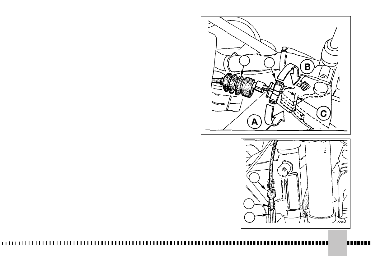
AJUSTE EMBRAGUE
El embrague no necesita, por lo
general, más ajustes que el de la
tensión del cable utilizando el
grupo de ajuste colocado en el
manillar. Por lo general, basta
con actuar en el tornillo de ajuste
colocado en el manillar para
recuperar el juego debido al
alargamiento de la transmisión
flexible. La palanca de mandos
tiene que tener siempre una
carrera en vacío C (aproxim. 3
mm) antes de desembragar. Para
regular este juego, actúe en el
ajuste 2 después de extraer el
capuchón de goma 1; girando el
ajuste en el sentido indicado por
la flecha A se reduce el juego C
mientras girändolo en el sentido
indicado por la flecha B se
aumenta el juego.
Hay otra posibilidad de ajuste y
es la que da el tensor (1)
colocado a la derecha del
bastidor.
Si, luego del ajuste, el embrague
patina bajo carga o arrastra
incluso cuando está
desembragado, se debe
desmontar para las
comprobaciones del caso.
Para realizar estas operaciones
diríjase al Concesionario.
1. Cappuccio in gomma
2. Vite di registro
1. Rubber cap
2. Adjusting screw
1. Capuchon en gomme
2. Vis de réglage
1. Gummikappe
2. Einstellschraube
1. Capuchón de goma
2. Tornillo de ajuste
1. Vite di registro
2. Controdado
3. Cappuccio in gomma
1. Adjusting screw
2. Locknut
3. Rubber cap
1. Vis de réglage
2. Contre-écrou
3. Capuchon en gomme
1. Einstellschraube
2. Gegenmutter
3. Gummikappe
1. Tornillo de ajuste
2. Contratuerca
3. Capuchón de goma
1
2
3
2
1
95
Page 96

CONTROLLO CANDELA
Se la candela di serie deve
essere sostituita, è importante
che la nuova abbia lo stesso
grado termico e la medesima
lunghezza di filettatura.
SPARK PLUG CHECK
If standard spark plug is to be
replaced, it is important that
new spark plug have the same
heat range and thread length.
CONTROLE DE LA BOUGIE
Si la bougie de série doit être
remplacée, il est important que la
nouvelle ait le même degré
thermique et la même longueur
de filetage.
KERZENKONTROLLE
Wenn die Serienkerze
ausgewechselt werden muss, ist
es wichtig, dass die neue
denselben Wärmegrad und
dieselbe Gewindelänge hat.
Esatto grado termico:
La punta dell'isolante è secca ed
il colore è marrone chiaro o
grigio.
Grado termico elevato:
La punta dell'isolante è secca e
coperta da incrostazioni scure.
Grado termico basso:
La candela si è surriscaldata e la
punta dell'isolante è vetrosa e di
colore bianco o grigio.
Controllare la distanza tra gli
elettrodi con uno spessimetro.
Regolare la distanza “A” a
seconda del tipo di candela,
come indicato a pag. 26.
Una distanza maggiore può
causare difficoltà di avviamento e
sovraccarico della bobina.
Correct heat grade:
The tip of the insulator should be
dry and the colour should be light
brown or grey.
High heat grade:
In this case, the insulator tip is
dry and covered with dark
deposits.
Low heat grade:
In this case, the spark plug is
overheated and insulator tip is
vitreous, white or grey in colour.
Check distance between
electrodes using a thickness
gauge, and adjust distance “A”
according to the type of spark
plug, as shown on page 26.
A wider gap may cause
difficulties in starting engine and
in overloading coil.
Degré thérmique exact:
La pointe de l’isolant est sèche et
sa couleur est marron clair ou
gris.
Degré thérmique élevé:
La pointe de l’isolant est sèche et
couverte d’incrustations foncées.
Degré thérmique bas:
La bougie est surchauffée, la
pointe de l’isolant est vitreuse et
de couleur blanche ou grise.
Régler la distance “A” à
selon le type de bougie et
d’après les instructions données
à la page 26.
Une distance supérieure peut
entraîner des difficultés de
démarrage et de surcharge de la
bobine.
Exakter Wärmegrad:
Die Spitze des Isolierstoffes ist
trocken, und die Farbe ist
hellbraun oder grau.
Hoher Wärmegrad:
Die Spitze des Isolierstoffes ist
trocken und von dunklen
Verkrustungen bedeckt.
Niedriger Wärmegrad:
Die Kerze hat sich überhitzt, un
die Spitze des Isolierstoffes ist
glasig und hat eine weisse oder
graue Farbe.
Das Abstand “A” je nach
Kerzentyp einstellen, wie auf Seite
27 angegeben.
Eine grössere Entfernung kann
Anlasschwierigkeiten und
Überbelastung der Spule
verursachen.
96
Page 97
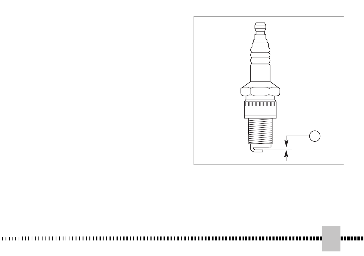
CONTROL BUJIA
Si la bujía de serie se debe
sustituir, es importante que la
nueva tenga el mismo grado
térmico y la misma longitud de
fileteado.
Grado termico exacto:
El extremo del aislante está seco
y el color es marrón claro o gris.
Grado termico elevado:
El extremo del aislante está seco
y cubierto de incrustaciones
oscuras.
Grado termico bajo:
La bujía se ha recalentado y la
punta del aislante es cristalina y
de color blanco o gris.
Regule la distancia “A” a
de acuerdo con el tipo de buja
como se indica en la pág. 27.
Una distancia mayor puede
causar dificultades de puesta en
marcha y sobrecarga de la
bobina.
A
97
Page 98

Una distanza minore, può
causare problemi di
accelerazione, di funzionamento
al minimo e di prestazioni alle
basse velocità.
AVVERTENZA*: Effettuare
l’eventuale sostituzione della
candela con una “più calda” o
“più fredda” con estrema
cautela. Una candela di grado
termico troppo elevato può
causare preaccensioni con
possibili danni per il motore.
Una candela di grado termico
troppo basso può causare un
notevole aumento dei depositi
carboniosi.
Prima di montare la candela,
pulire accuratamente gli
elettrodi e l'isolante con uno
spazzolino metallico.
AVVERTENZA*: Non utilizzare
mai una candela di grado
termico non corretto.
AVVERTENZA*: La candela
deve essere serrata alla coppia
prescritta. Diversamente
potrebbe surriscaldarsi e
provocare danni al motore.
A gap that is too narrow may
cause difficulties when
accelerating, when idling the
engine or when performing at low
speeds.
CAUTION*:
Select a spark
plug with a colder or hotter
heat range carefully and
cautiously.
A spark plug with too hot a
heat range may lead to
preignition and possible
engine damage.
A spark plug with too cold a
heat range may foul as the
result of too much carbon
buildup.
Before mounting spark plug,
carefully clean electrodes and
insulator with a metallic brush.
CAUTION*:
Never use a spark
plug of an improper heat
range.
CAUTION*:
The spark plug
must be securely tightened.
An improperly tightened plug
can become very hot and
possibly damage the engine.
Une distance inférieure peut
causer des problèmes
d’accélération, de
fonctionnement au ralenti et de
performance, lorsque les vitesses
sont peux élevées.
AVIS * : Il ne faut pas négliger
certaines précautions quand
on remplace la bougie avec
une “plus chaude” ou “plus
froide”. Rappelez-vous que
une bougie ayant un dégré
thermique trop élevé peut
provoquer des préallumages
et endommager le moteur et
que une bougie avec un
dégré thermique trop bas
peut provoquer un
acroissement remarquable
des dépôts de carbone.
Avant de monter la bougie,
nettoyez soigneusement les
électrodes et l’isolant avec une
brosse métallique.
AVIS * : Ne jamais utiliser
une bougie avec un dégré
thermique incorrect.
AVIS * : Serrer la bougie à la
couple de serrage préétablie.
Autrement, la bougie pourrait
surchauffer et causer des
dommages au moteur.
Eine geringere kann
Beschleunigungsprobleme,
Probleme
des Funktionierens bei Niedrigstand
und Probleme der Leistungen bei
niedrigen Geschwindigkeiten
werursachen.
WARNHINWEIS * : Der
eventuelle Austausch der
Zündkerze mit einer “heißeren”
oder “kälteren” ist mit
äußerster Sorgfalt
durchzuführen. Eine Zündkerze
mit zu hohem Wärmegrad kann
Frühzündungen verursachen
mit möglichen Motorschäden.
Eine Zündkerze mit zu
niedrigem Wärmegrad kann die
Kohlenablagerungen erheblich
erhöhen.
Bevor man die Kerze
montiert, die Elektroden und den
Isolierstoff mit einer kleinen
Metallbürste sorgfältig säubern.
WARNHINWEIS* : Niemals eine
Zündkerze mit unrichtigem
Wärmegrad benutzen.
WARNHINWEIS* : Die
Zündkerze muß mit dem
vorgeschriebenem
Drehmoment angezogen sein.
Andernfalls könnte sie sich
überhitzen und Schäden am
Motor verursachen.
REGOLATORE DI TENSIONE
Il regolatore di tensione (1) è
fissato sul telaio, tra i due
radiatori.
98
VOLTAGE REGULATOR
The voltage regulator (1) is
located on the frame, between
the radiators.
REGULATEUR DE TENSION
Le régulateur de tension (1) est
fixé sur le cadre, entre les deux
radiateurs.
SPANNUNGSREGLER
Die Spannungsregler (1) befestigt
ist in den Rahmen, zwischen dem
Kühler.
Page 99

Una distancia menor, puede
causar problemas de aceleración,
de funcionamiento ralentí y de
prestaciones a bajas velocidades.
ADVERTENCIA*: Efectuar la
eventual sustitución de la
bujía, con otra “más caliente”
o “más fría”, con mucho
cuidado. Una bujía de grado
térmico demasiado elevado
puede causar preencendido
con posibles daños al motor.
Una bujía de grado térmico
demasiado bajo puede causar
un notable aumento en los
depósitos carbonosos.
de montar la bujía, limpie muy
bien los electrodos y el aislante
con un cepillo metálico.
ADVERTENCIA *: No utilizar
nunca una bujía de grado
térmico incorrecto.
ADVERTENCIA *: La bujía
tiene que ser apretada al par
indicado. En caso contrario
podría sobrecalentarse y
provocar daños al motor.
Antes
REGULADOR DE TENSION
El regulator de tension (1) está
fijàdo sobre el bastidor, entre los
dos radiadores.
99
Page 100

CONTROLLO FILTRO ARIA
Ruotare in senso antiorario il perno
posteriore (1), rimuoverlo ed estrarre la
sella svincolandola dalla vite di fissaggio
anteriore. Togliere la vite (3). Rimuovere
il filtro aria completo (4). Separare il filtro
(5) dal telaietto (6).
PULIZIA FILTRO ARIA
Lavare il filtro con un detergente
specifico (AGIP "Filter clean foam air
detergent fluid" o prodotto similare) ed
asciugarlo perfettamente (lavare il filtro
con benzina solo in caso di necessità).
Immergerlo in olio speciale per filtri
(AGIP "Foam air filter protection oil" o
prodotto similare) e strizzarlo per far
uscire l’olio superfluo.
ATTENZIONE*: Per la pulizia
dell’elemento filtrante non utilizzare
benzina o solvente a basso punto di
infiammabilità; potrebbero verificarsi
incendi o esplosioni.
ATTENZIONE*: Pulire l’elemento
filtrante in un’area ben ventilata e non
avvicinare scintille o fiamme all’area
di lavoro.
MONTAGGIO
Mettere del grasso sul bordo (C) del
filtro dal lato dell'alloggiamento per
ottenere una buona tenuta. Nel
rimontare il filtro nel proprio
alloggiamento, assicurarsi che
l'appendice A sia rivolta verso l'alto e
che lo spigolo B si trovi sul lato inferiore
sinistro della scatola filtro. Rimontare gli
altri particolari precedentemente rimossi.
AVVERTENZA*: In caso di errato
montaggio del filtro, potrebbero
entrare sporcizia o polvere,
provocando l’usura rapida dei
segmenti pistone e del cilindro.
AIR FILTER CHECK
Turn rear pin (1) anticlockwise,
remove the saddle from the front
fixing screw.
Remove screw (3). Remove air filter
(4). Separate filter (5) from frame (6).
AIR FILTER AND CLEANING
Wash the filter with a specific
detergent (AGIP” Filter clean foam air
detergent fluid” or similar) then dry it
fully (wash filter with gasoline only in
case of necessity).
Plunge the filter in special oil for filters
(AGIP "Foam air filter protection oil" or
similar), then wring it to drain
superfluous oil.
CAUTION*: Do not use gasoline
or a low flash-point solvent to
clean the element. A fire or explosion could result.
CAUTION*: Clean the element in
a well ventilated area, and do not
allow sparks or flames anywhere
near the working area.
ASSEMBLY
To ensure tight fit, slightly (C) grease
filter edge on side facing filter
housing.
While re-inserting the filter into its
housing, make surs that piece A is
turned upwards and edge B is on the
left lower side of the filter case.
Reassemble the parts previously
removed (battery: connect the positive
cable first).
CAUTION*: If the element assembly is not installed correctly, dirt
and dust may enter and the engine resulting in rapid wear of the
piston rings and cylinder.
CONTROLE FILTRE A AIR
Tourner le pivot arrière (1) en sans antihoraire, enlever la selle de la vis de fixation
avant. Enlever la vis (3). Enlever le filtre à
air complet (4). Séparer le filtre (5) du cadre
(6).
NETTOYAGE FILTRE A AIR
Laver le filtre avec un détergent spécifique
(AGIP” Filter clean foam air detergent fluid”
ou produit similaire) et lui essuyer
parfaitement (laver le filtre avec essence
seul en cas de nécessité). Le plonger en
huile spéciale pour filtres (AGIP” Foam air
filter protection oil” ou
produit similaire) et l’essorer pour faire
sortir l’huile superflue.
ATTENTION * : Pour le nettoyage de
l’élément filtrant ne jamais utiliser de
l’essence ou du solvant à bas point
d’inflammation, car des incendies ou des
explosions pourraient se vérifier.
ATTENTION * : Le nettoyage de l’élément
filtrant doit se passer dans des milieux
très bien ventilés. Veillez à ce que des
flammes ou des étincelles ne soient
jamais approchées à la zone de travail.
MONTAGE
Pour avoir une bonne étachéité, graisser le
borde (C) du filtre dans la direction du
logement.
Lorsque le filtre est remis en place,
s'assurer que l'extrémité A soit tournée vers
le haut et que l'angle B se trouve sur le côté
inférieur gauche de la boîte filtre. Remonter
les autres pièces enlevées précédemment
(batterie: brancher le câble positif pour le
premier).
ATTENTION * : Au cas d’un montage
erroné du filtre, de la crasse ou de la
poussière pourraient s’introduire dans le
filtre et provoquer une usure rapide des
segments du piston et du cyclindre.
KONTROLLE LUFTFILTER
Den hinteren Zapfen (1) gegen den
Uhrzeigersinn drehen, den Sattel von der
vorderen Befestigungsschraube befreien und
ihn herausnehmen. Schraube (3) entfernen.
Vollstaendiges Luftfilter (4) abnehmen. Filter
(5) vom Rahmen (6) trennen.
REINIGUNG LUFTFILTER
Den Filter mit einem spezifischen
Reinigungsmittel waschen (AGIP "Filter clean
foam air detergent fluid" oder ein ähnliches
Produkt) und es sorgfaeltig reinigen (den Filter
mit Benzin waschen nur bei Notwendigkeit).
Den Filter in Spezial-Filteroel (AGIP "Foam air
filter protection oil" oder ein ähnliches Produkt
) eintauchen lassen, danach sorgfaeltig
ausringen, um das uebersohuessige Oel
ausfliessen zu lassen.
ACHTUNG * : Zur Reinigung des
Filterelementes kein Bezin oder Lösemittel
mit geringem Entzündbarkeitspunkt
benutzen ; es könnten Brände oder
Explosionen auftreten.
ACHTUNG * : Das Filterelement in einem
gut belüftetem Bereich reinigen und sich
nicht mit Funken oder Flammen dem
Arbeitsgebiet nähern.
MONTAGE
Zur Erreichung eines guten Halts auf der Seite
des Gehäuses Fett (C) auf den Rand des
Filters auftragen. Beim
Wiederzusammensetzen des Filters in sein
Lager sich vergewissern, dass der Endteil A
nach oben gerichtet ist und die Kante B auf
der unteren linken Seite des Filtergehäuses ist.
Die vorher abgenommenen Teile wieder
anbringen (für die Batterie zuerst den Plus-Pol
anschliessen).
ACHTUNG * : Im Falle der falschen
Filtermontage könnte Schmutz und Staub
eindringen und den schnellen Verschleiß
der Kolbenringe und des Zylinders
verursachen.
100
 Loading...