

Page 1

Service Supplement
HP LaserJet 5P / 5MP /
6P / 6MP Printer
(C3150A / C3155A /
C3980A / C3982A)
Page 2

Service Supplement
HP LaserJet 5P / 5MP
Printer
(C3150A / C3155A)
Page 3

© Copyright HewlettPackard Company 1995
All Rights Reserved. Reproduction, adaptation, or
translation without prior
written permission is prohibited, except as allowed
under the copyright laws.
Publication number
C3150-90002
First edition, May 1995
Printed in USA
Warranty
The information contained
in this document is subject
to change without notice.
Hewlett-Packard makes
no warranty of any kind
with regard to this material, including, but not
limited to, the implied
warranties or merchantability and fitness for a
particular purpose.
Hewlett-Packard shall not
be liable for errors contained herein or for incidental or consequential
damaged in connection
with the furnishing, performance, or use of this material.
WARNING
Electrical Shock Hazard
To avoid electrical shock,
use only supplied power
cords and connect only to
properly grounded (3-hole)
wall outlets.
Hewlett-Packard Company
11311 Chinden Boulevard
Boise, Idaho 83714
Page 4

Conventions
This manual uses the following conventions:
Color is used to em ph asize items which are impor t ant to the mate r i al
under discussion.
The names of major pr inte r p ar ts and ass emblies are Capitalized.
Bold is used for emphasis, p ar ticularly in situations whe re italic type
would be confusing.
Italic type is used to indicate relate d doc uments or emphas is.
COMPUTER type indicates text as seen on a computer monitor.
Note
CAUTION
WARNING!
Notes contain important information set off from
the text.
Caution messages alert you to the possibility of
damage to equipme nt or los s of dat a.
Warning messages alert you to the possibility of
personal injury.
i
Page 5

ii
Page 6

Contents
Overview . . . . . . . . . . . . . . . . . . . . . . . . . . . . . 2
Product Information . . . . . . . . . . . . . . . . . . . . . . 3
Key Printer Locations and Parts. . . . . . . . . . . . . . . . 4
Model and Serial Numbers . . . . . . . . . . . . . . . . . . 5
Product Specifications . . . . . . . . . . . . . . . . . . . . 6
Documentation an d Softwar e . . . . . . . . . . . . . . . . 8
Documentation . . . . . . . . . . . . . . . . . . . . . . . . . 8
Software . . . . . . . . . . . . . . . . . . . . . . . . . . . . 9
New Product Features . . . . . . . . . . . . . . . . . . . . . 10
The HP LaserJet 5P/5MP Status Panel . . . . . . . . . . . 10
The GO and RESET Buttons . . . . . . . . . . . . . . . . . 10
The Status Lights . . . . . . . . . . . . . . . . . . . . . . . 11
Common LED patterns . . . . . . . . . . . . . . . . . . . . 12
Paper Movement Overview . . . . . . . . . . . . . . . . . . 16
Infrared Comm un ication . . . . . . . . . . . . . . . . . . . 18
To Print Using the Infrared Port . . . . . . . . . . . . . . . 20
Troubleshooting IR Printing Pr oble ms . . . . . . . . . . . . 22
Interface Connections . . . . . . . . . . . . . . . . . . . . . 25
The Parallel Printer Interfaces . . . . . . . . . . . . . . . . 26
Resource Saving . . . . . . . . . . . . . . . . . . . . . . . . 27
I/O Buffering . . . . . . . . . . . . . . . . . . . . . . . . . . 28
Service Mode, PJ L De faults . . . . . . . . . . . . . . . . . 30
Test Pages and Resets . . . . . . . . . . . . . . . . . . . . . 32
Printing a Self-Test Page . . . . . . . . . . . . . . . . . . . 33
Life Expectancy of Con sum a ble s . . . . . . . . . . . . . . 36
Removal and Replacement . . . . . . . . . . . . . . . . . . 37
Overview . . . . . . . . . . . . . . . . . . . . . . . . . . . . 37
Required Tools . . . . . . . . . . . . . . . . . . . . . . . . . 38
Removing the Power Door . . . . . . . . . . . . . . . . . . . 39
Removing the I/O Cover . . . . . . . . . . . . . . . . . . . . 39
Removing the Left Side Cover . . . . . . . . . . . . . . . . . 40
Removing the Top Cover . . . . . . . . . . . . . . . . . . . . 41
Removing the Tray 1 Pickup Assembly . . . . . . . . . . . . 44
Removing the Formatter Board and Shield . . . . . . . . . 47
Removing the Fusing Assembly . . . . . . . . . . . . . . . . 50
Removing the DC Controller Assemblies . . . . . . . . . . . 51
Troubleshootin g . . . . . . . . . . . . . . . . . . . . . . . . 55
Continuable Data Error Light Patterns . . . . . . . . . . . 56
Error 53 -- Memory/SIMM Errors . . . . . . . . . . . . . . . 58
Fatal/Service Errors . . . . . . . . . . . . . . . . . . . . . . 60
Infrared Por t Not Respon ding . . . . . . . . . . . . . . . . . 65
Using the Infrared Te st Tool . . . . . . . . . . . . . . . . . 66
Parts and Diagrams . . . . . . . . . . . . . . . . . . . . . . 68
Ordering Parts . . . . . . . . . . . . . . . . . . . . . . . . 68
Ordering Consumables . . . . . . . . . . . . . . . . . . . . 69
iii
Page 7

Accessories . . . . . . . . . . . . . . . . . . . . . . . . . . . 86
Index . . . . . . . . . . . . . . . . . . . . . . . . . . . . . . . 87
iv
Page 8

HP LaserJet 5P Printer
Service Supplement
Page 9

HP LaserJet 5P Printer Service Supplement
Overview
Overview
The HP LaserJet 5P and 5MP pri n ters (HP Pr o d uc t Numbe rs
C3150A and C3155A) have many service and repair processes in
common with their prede cessor s , the HP LaserJe t 4L/4ML and
4P/4MP printers. These processes are documented in the
Combined Service Manual for the HP LaserJet 4L/4ML
(C2003A/C2015A) HP LaserJet 4P/4MP (C2005A/C2040A). The
purpose of this app e nd ix is to pro v ide supplemental ser vic e
information that is unique to the HP LaserJet 5P and 5MP
printers.
2
Page 10

HP LaserJet 5P Printer Service Supplement
Product Information
Product Information
Printer Features
Features
Print Speed 6 PPM
Text & Graphics Resolution 600 dpi; plus Resolution Enhancement Technology (REt)
Printer Languages
HP LaserJet 5P
HP LaserJet 5MP
Monthly Usage (pages) Up to 12,000
Memory: 2MByte on-board standard memory
Tray 1 Capacity 100
Tray 2 Capacity 250
Output Tray capacity 100
Internal Typefaces
HP LaserJet 5P
LaserJet 5MP
Standard Interfaces 2 Parallel (B connector, C connector)
Power Control Power switch
NVRAM Yes
Status Panel 2 Buttons
Economode (toner saving) yes
Min. Paper Size
(using flat paper path)
1
SIMM includes 1 MByte additional memory.
Enhanced PCL 5
PostScript Level 2
Enhanced PCL 5
45 PCL
45 PCL, 35 PS
1 LocalTalk
1 SIR
5 LEDs
3 x 5 inch
(76 x 127mm)
1
3
Page 11
HP LaserJet 5P Printer Service Supplement
Product Information
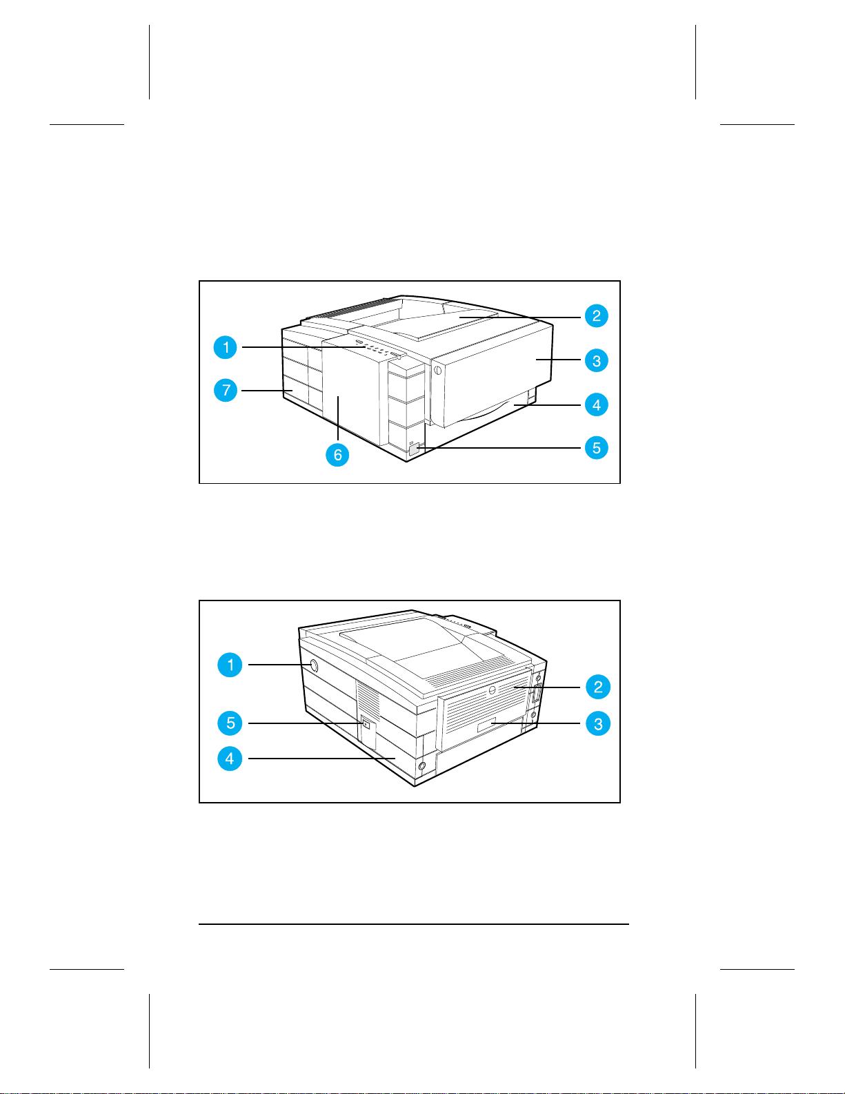
Key Printer Locations and Parts.
Figure 1 Front View
1. Status Panel 5. Infrared Port and Status Light
2. Top Output Tray 6. Removable Side Panel
3. Tray 1 - MultiPurpose Tray 7. Interface Cable Door
4. Tray 2 - 250-sheet Paper Cassette
Figure 2 Rear View
1. Top Cover Release Button 3. Serial Number Label
2. Rear Output Tray 4. Power Cable Door
5. On/Off Button
4
Page 12
HP LaserJet 5P Printer Service Supplement
Product Information
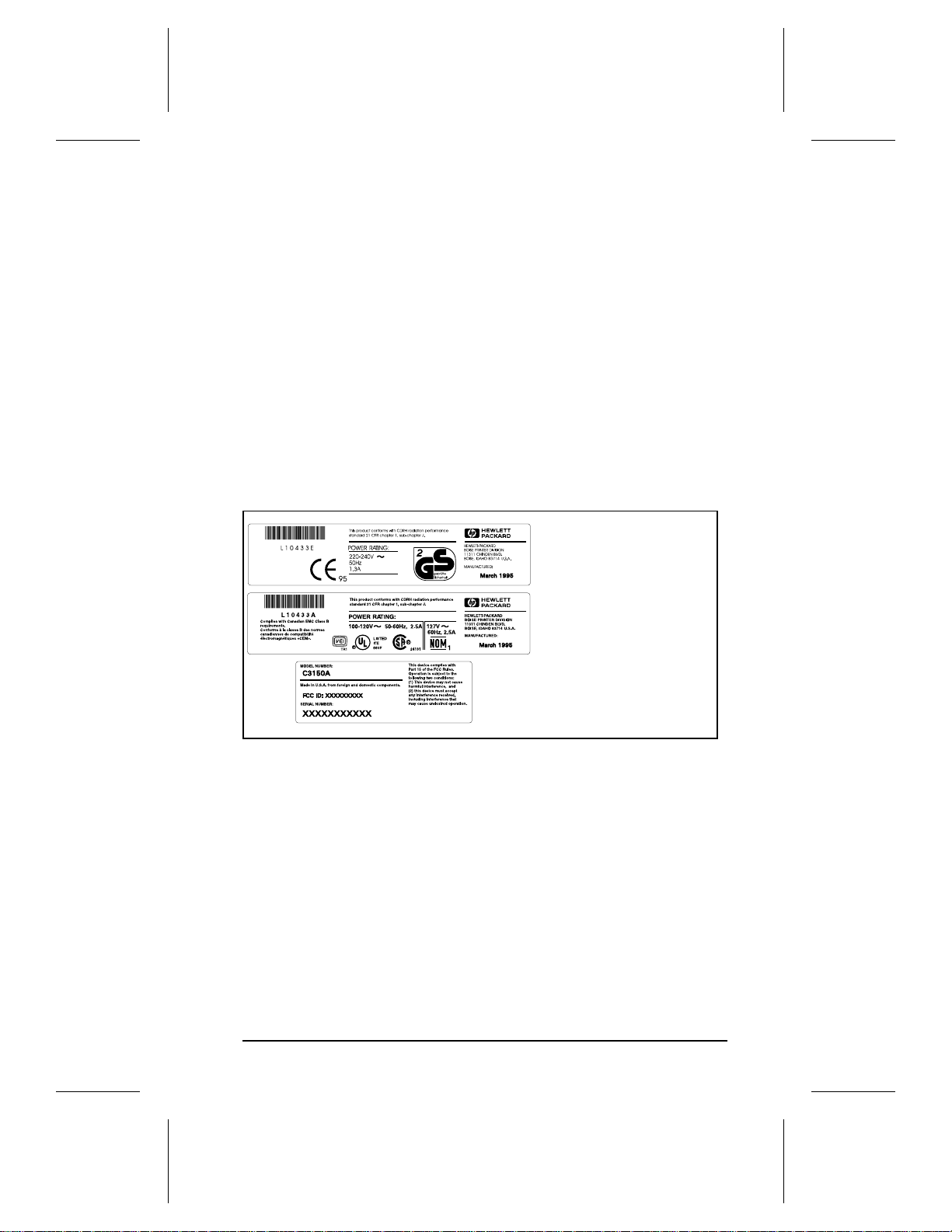
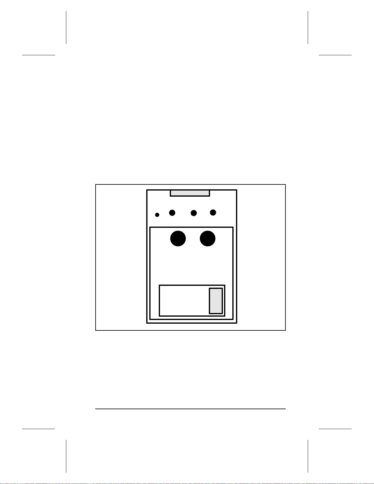
Model and Serial Numbers
The model number and serial numbe rs ar e liste d on ident ific at io n
labels located on the rear of the printer. The model number is
alphanumeric, such as C3150A for the HP LaserJet 5P printer and
C3155A for the HP LaserJet 5MP printer.
The serial number contains information about the Country of
Origin, the Revision Le ve l, t he Prod uc t io n Code , and pr oduction
number of the printer.
The rear labels also contain power rating and regulatory
information as show n in Figur e 3.
Figure 3 Sample Model and Serial Number Labels
5
Page 13
HP LaserJet 5P Printer Service Supplement
Product Specifications
Product Specifications
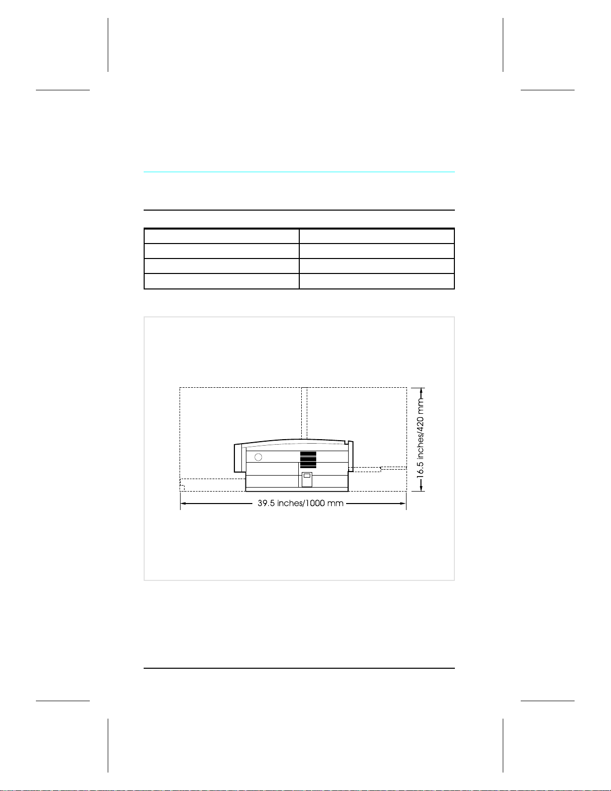
Dimensions
Width 15.79 in. (401 mm)
Depth 17.38 in. (441.7mm)
Height 7.92 in. (201.1mm)
Weight 15.4 lbs. (7 kg)
Figure 4. Location Space Requirements
6
Page 14
HP LaserJet 5P Printer Service Supplement
Product Specifications
Electrical Specifications
Power Requirements 100/120V (+/- 10%) 50/60Hz (+/- 2Hz)
Power Consumption (typical for HP
LaserJet 5P and HP LaserJet 5MP)
Minimum recommended circuit
capacity
127 Volts NOM
During printing - 165 W (average) During printing - 165 W (average)
During standby – 5W (instant power
save)
During power save mode - 5 W
4 Amps 1.8 Amps
220/240V (+/- 10%) 50 Hz (+/- 2Hz)
During standby – 5W (instant power
save)
During power save mode - 5 W
Environmental Specifications
Item Operating Printing Storage/Standby
Temperature
(printer and toner cartridge)
Relative humidity 10% to 80% 10% to 90%
59° to 89° F (15° to 32.5° C) -4° to 104° F (-20° to 40° C)
Acoustic Emissions (Per ISO 9296)
Operator Position Bystander (1m) Sound Power
Printing L
Power Save* L
*In this mode, the printer is essentially quiet.
52dB(A) L
pAm
<22dB(A) L
pAm
46dB(A) L
pAm
<22dB(A) L
pAm
6.0 bels(A)
WAd
<3.6 bels(A)
WAd
7
Page 15

HP LaserJet 5P Printer Service Supplement
Documentation and Software
Documentation and Software
Documentation
You can order the documents listed below. There is a charge for
some document s.
Table 1. Related Documentation
Title Part Number
The PCL/PJL Technical Reference Package contains the following
5961-0601
documents*
PCL5 Printer Language Technical Reference Manual.
Explains the PCL 5 printer language for experienced users and
programmers.
Printer Job Language Technical Reference Manual.
Explains HP’s Printer Job Language (PJL) for experienced users
and programmers.
PCL/PJL Technical Quick Reference Guide.
PCL Comparison Guide.
Describes the different implementation of commands and
extensions across the printer family supporting PJL and PCL 5.
HP LaserJet 5P/5MP Printer User’s Manual C3150-90901
HP LaserJet 5MP Macintosh Notes* (included with HPLaserJet
C3155-90901
5MP Printer and optional Adobe PostScript Level 2 SIMM)
HP LaserJet Printer Family Paper Specification Guide* 5002-1801
* This item must be ordered through HP Parts Direct Ordering, (800) 227-
8164. Outside the U.S., see the ordering information in "Parts and Diagrams"
later in this chapter.
8
Page 16

HP LaserJet 5P Printer Service Supplement
Documentation and Sof tw a re
Software
The following softwar e drive r d isk ettes are ship p e d with the
C3150A HP LaserJet 5P printer:
• The HP LaserJet 5P DOS Utilities and DOS Printer Drivers
diskette. The DOS utilities include a Status Monitor and
Remote Control Panel. The DOS printer drive rs inc lud e
WordPerfect (versions 5.1, 5.1+, and 6.0) and Lotus 1-2-3
(versions 2.3, 2.4, 3.1 and 3.4).
•
The HP LaserJet Printing System for Microsoft Windows 3.1
and 3.11 contains the PCL drivers and the HP Font Sm ar t
utility for font management.
The following softwar e drive r d isk ettes are ship p e d with the
C3155A HP LaserJet 5MP printer:
• The HP LaserJet 5MP Printer Software for Macintosh. Supports
System 6.07 to 7.5.
• The PostScript Printer Software for Windows 3.1 and 3.11
includes the PostScript drivers and the HP FontSmart utility
for font management.
9
Page 17
HP LaserJet 5P Printer Service Supplement
New Product Features
New Product Features
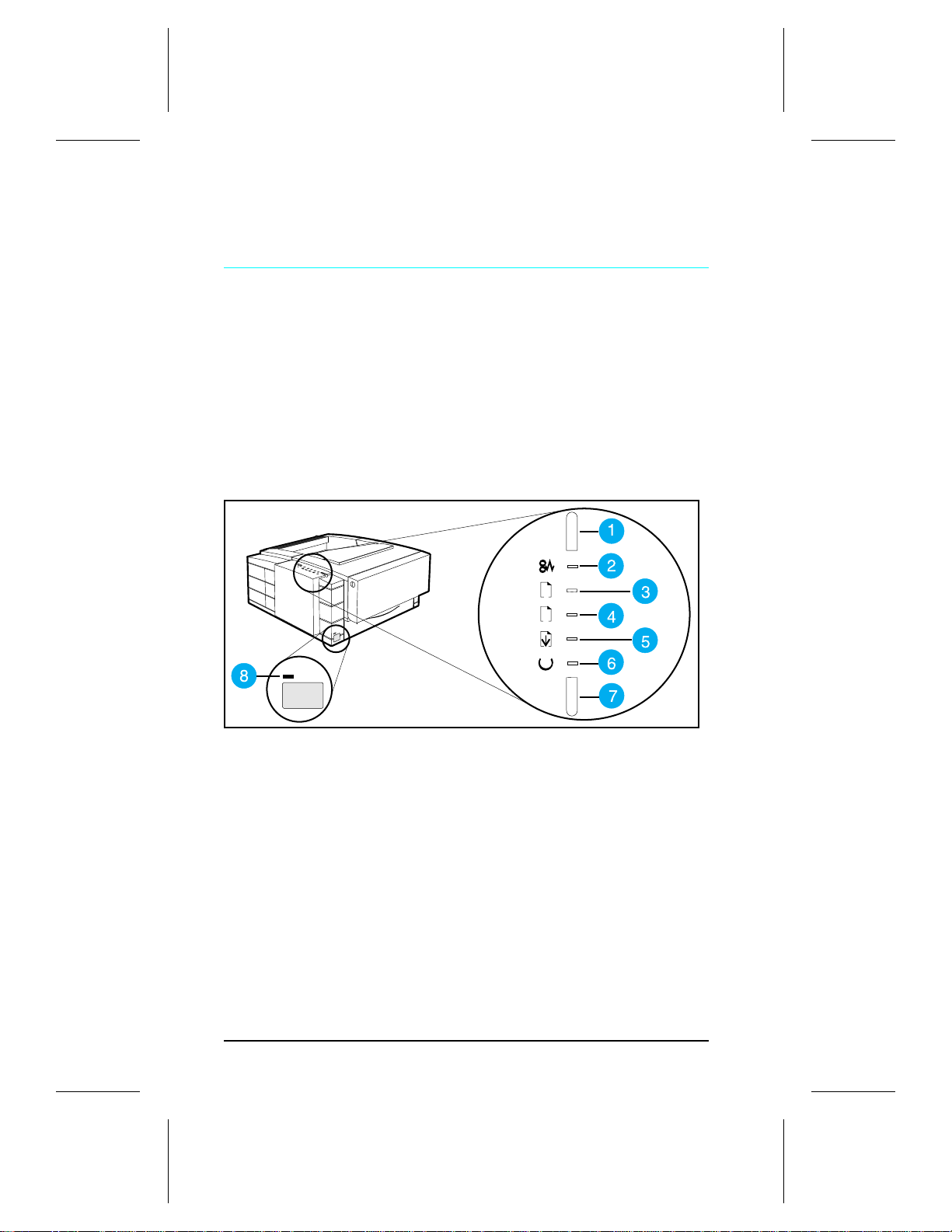
The HP LaserJe t 5P/ 5MP Status Panel
This HP LaserJet printer has been des igne d to be contr olle d
mainly by software. However, some simple functions are also
available from the status panel. You also receive status
information about the operation of the IrD A- comp atible inf rar ed
(IR) port from the status light just above the port (for more
information, see “To Pr int Us ing the In fr ar ed Po rt, ” later in this
appendix).
1
2
Figure 5 Status Panel Button s and Ligh t s
1. RESET button 5. DATA status light
2. ERROR status light 6. READY status light
3. TRAY 1 status light 7. GO button
4. TRAY 2 status light 8. IR port status light
The Status Panel consists of two buttons you use to complete
certain tasks and five status lights that indicate the status of the
printer (see Figure 5).
The GO and RESET Buttons
The printer has two button s: GO an d RESET.
10
Page 18

HP LaserJet 5P Printer Service Supplement
New Product Features
Pressing the GO bu tton :
• Tells the printer to resume printin g.
• Prints a demo page. The printer must be in Ready Mode (the
green Ready light on steady).
• Prints a self-test page when pressed simultaneou sly wit h the
RESET button. The printe r m u st be in Read y Mo d e (t he gre en
Ready light on steady).
Pressin g the RE S E T b ut to n:
• Clears incomple te p rint jo b s fro m the p r inte r’ s mem o r y.
• Clears errors.
• Removes all temporary fonts and macros.
• Returns all printer settings to the default values that you
selected.
The Status Lights
There are five Status Panel lights on the printer :
• ERROR
• TRAY 1
• TRAY 2
• DATA
• READY
These lights indicate the curr ent st atu s of the p rinter by
displaying an amber or a green hue and flashing individually or
sequentially as a group (cascading).
The status light above the IR port indicates the cur rent status of
the IR port by displaying a green hue. This status light comes on
only when the IR port is being used—the Statu s Pane l lights
operate the same for the IR port as they do for any other port on
the printer.
ERROR (amber)
Indicates an error condition, such as a pap er jam, missing toner
cartrid ge , or the p r inte r ’ s top c ove r is op e n.
11
Page 19

HP LaserJet 5P Printer Service Supplement
New Product Features
TRAY 1 (amber)
Tray 1 (the MP tray) is empty. Add paper to Tray 1. When the
Tray 1 light is flashing, the printer is waiting for paper to be
manually fed into Tray 1. On ce you hav e inser ted the paper , you
must press the G O butt on to fee d the paper.
TRAY 2 (amber)
Tray 2 (the Paper Cassette) is empty. Add pape r to Tray 2.
DATA (gree n)
When the Data light is on, the printer is printing. When the Ready
light and the Data light are both on, the printer still has unprinted
data in its memory. Either press GO to print the remaining data,
or press RESET to clear the d ata fr om the pr i n ter’s me mo r y .
READY (green)
The printer is in Ready Mo de whe n th e Read y light is on. If the
light is flashing, the printer is currently receiving data or in the
process of printing.
IR Port Status Light (green)
If this light is on, it indic at es that an infr ar e d (I R) con ne c tio n has
been established.
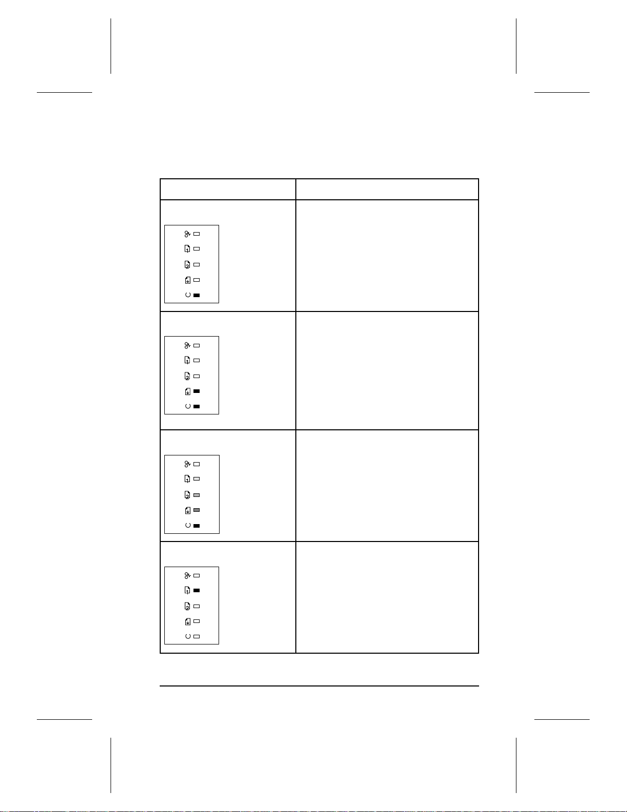
Common LED patterns
The chart following shows the light patterns for normal HP
LaserJet 5P/5MP printer states.
12
Page 20
HP LaserJet 5P Printer Service Supplement
New Product Features
Light Pattern Description
The printer is in Ready Mode and is ready to
print. Press the GO button to print a demo
page. Press the GO and RESET buttons to
print a self-test page.
The printer has received data. If the Ready
light is flashing, the printer is processing the
data—wait for the next page to be printed. If
the Data light and the Ready light are both on
for an extended period of time (the Ready light
does not begin to flash), press the GO button
to print the next page. A document or page
may take a long time to print if, for example,
the document or page contains complex text or
graphics.
The printer is warming up or resetting after you
have pressed the RESET button. The lights on
the Status Panel “cascade” (each light turns on
and off sequentially) until the printer is ready to
print.
Tray 1 (the MP Tray) is empty. Add paper to
the tray. If the Tray 1 light is flas hing, the
printer is waiting for paper to be manually fed
into Tray 1. Once you have inserted the paper,
you must press the GO button to feed the
paper.
13
Page 21
HP LaserJet 5P Printer Service Supplement
New Product Features
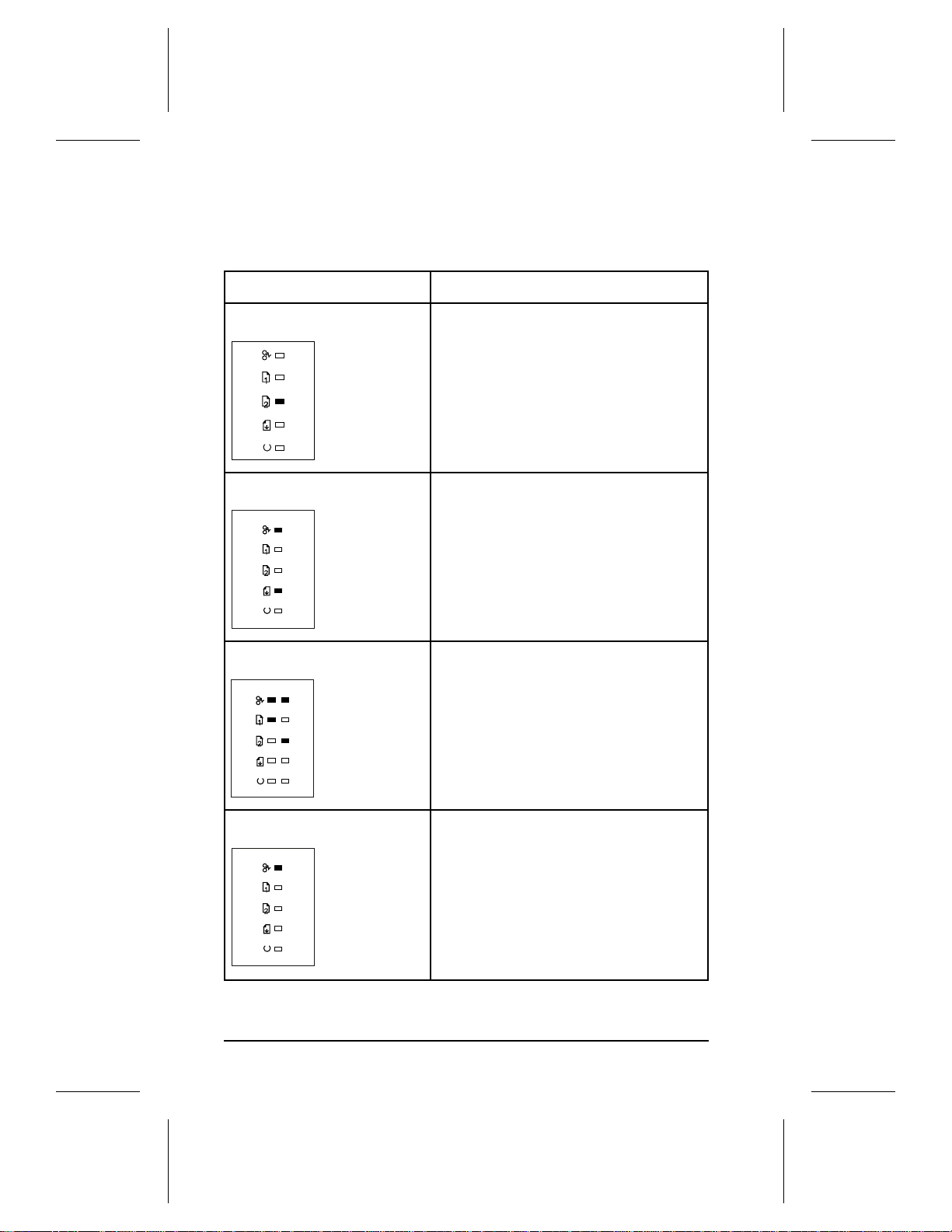
Light Pattern Description
Tray 2 (the Paper Cassette) is empty. Add
paper to the tray.
A data error has occurred. Press the GO
button to continue printing (some data may be
lost). For more information, see “Data Error
Light Patterns,” later in this appendix.
14
A SIMM error has occurred. Make sure your
SIMM is installed correctly. Replace the SIMM
that caused the error. Or press the GO button
on the printer to continue without configuring
the SIMM that caused the error. If the SIMM
has more than one bank of memory, the good
banks will be automatically configured.
A recoverable error has occurred, such as a
paper jam, the top cover is open, or the toner
cartridge is missing.
Page 22
HP LaserJet 5P Printer Service Supplement
New Product Features
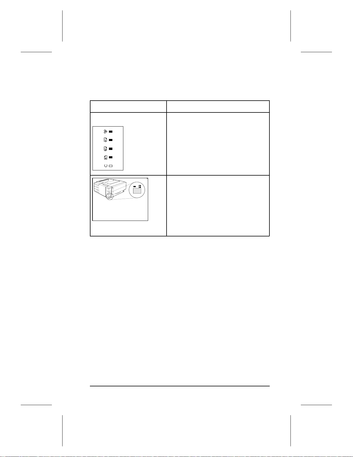
Light Pattern Description
A fatal error has occurred. Turn the printer off
and then back on. If the same light pattern
reappears, turn the printer off again and leave
it off for about 10 minutes, then turn it back on.
If the same light pattern reappears. refer to the
discussion of Fatal Errors in "Troubleshooting."
When the IR port status light is on, a
connection has been established. If you are
printing to the IR port and the status light does
not come on, make sure the printer is in Ready
Mode and that the IR port you are printing from
is within range of operation and is IrDAcompliant. If you continue to have trouble
printing, refer to the “Infrared Port Not
Responding” table, later in this section.
15
Page 23

HP LaserJet 5P Printer Service Supplement
New Product Features
Paper Movement Ove rview
The paper feed sys tem pic ks print media aut om atically from the
paper cassette or accepts it from the manual feed slot and delivers
it to the image formation system at precisely the right time. The
system then feeds the media to the fusing station, and deliver s the
finished product to the output posit io n, either the face-down
output tray on top of the printer, or through the face-up delivery
slot at the rear of the printer. The output path is user-selectable by
opening the rear output tray.
Figure 6 shows the possible paper paths and lo catio ns of the
various soleno ids , p hoto s en sor s and r oller s .
16
Page 24
HP LaserJet 5P Printer Service Supplement
New Product Features
DC Controller PCA
PS 3
Figure 6 HP LaserJet 5P Pri nter Paper Path
PS1 Input Paper Sensor Input Paper Sensor (PS1) Positions:
PS2 Tray 2 Paper Out Sensor A = Manual Feed Sense Position
PS3 Exit Paper Sensor B = Registration Sense Position
PS4 Winding Paper Sensor C = TOP Sense Position
PS5 Tray 1 Paper Out Sensor SL1 Tray 2 Solenoid
SL2 Tray 1 Solenoid
17
Page 25

HP LaserJet 5P Printer Service Supplement
New Product Features
Infrared Communication
The HP LaserJet 5P and 5MP pri n ters ar e equ ipp e d with a n
Infrared Datalink Association (IrDA) compliant port. The IrDA
specification allows "wire less " tran smis sio n of pr int data be tw een
a wide variety of hosts (primary) and peripheral (secondary)
devices. A primary device -- suc h as a PC or laptop computer -- is
capable of reading and writing data to anoth er primar y devic e or
writing to a secondary device, such as a printe r. Secondar y dev ice s
are read-only; they can n ot initiat e its own c ommun ic atio n, and ca n
only respond to a host command when properly add ressed.
The IrDA protocol uses a transceiver chip in both devices to send
and receive data packets. The packets are checked for validity, and
a response is sent by the secondary device indicating whe th er the
packets were complete or in error.
The IrDA protocol is contained in three layers:
• The physical electronics are the hardware elements in each
device for sending and receiving the data.
• The Link Access Protocol (LAP) layer controls the physical
layer, packetizes/unpacketizes data, and sets transmission
rates.
• The Link Management Protocol (LMP) layer routes data to and
from the host operating system (DOS/Windows).
The data flow is shown in Figure 7.
The LAP and LMP layers can reside in either firmware, softwar e,
or a combination of both. There are different LAP and LMP
protocols for primary and secondary devices.
The HP LaserJet 5P printe r has th e comple t e second ar y pro toco l,
and any host trying to communicate via the infrared (IR) port must
have the complete primary protocol installed. The primary protocol
software is the responsibility of the host supplier. It is not provided
by Hewlett-Packard Company with the printer.
IrDA communications can be obtained either via an inte rn al IR
port or an external IR accessory. Several manufacturers offer
complete accessory upgrades for both host and peripheral devices.
18
Page 26
HP LaserJet 5P Printer Service Supplement
New Product Features
primary
device
Application
GDI DDI
Ptr DVR
IRLMP
IRLAP
IR Physical
Transmitter
Receiver
ASCII Data
Windows
System
Standard Windows
LJ Printer Driver (SW)
IR Redirector
(Software)
IR Driver Packetizes
Data (SW or FW)
Protocol Serializer
IR Chip
Data Packets & Queries
Responses
Formatter
I/O Buffer
IRLMP
IRLAP
IR Physical
Receiver
Transmitter
secondary
device
ASCII to
Raster Data
ASCII
Data Buffer
Unpacks Data
Checks Packets
Protocol
Deserializer
IR Chip
Figure 7. IR Data Flow.
System Re quiremen ts
• Hardware
• Both the primary and secondary devices must be equipp ed with
an IrDA-compliant IR component. Older, non-IrDAcompliant devices may not be compatible with the HP Lase rJe t
5P/MP printers.
• Software
• The primary device must be loaded duri n g boo t-u p wit h sof tware
provided by the manufacturer for infrared operation.
• The primary device must be properly c onf igur e d with an inf r ar ed
COM port, IRQ level, and base address value .
• The infrared port must be inst alle d and selected in the Printe r s
section of the Windows Cont rol Panel.
19
Page 27
HP LaserJet 5P Printer Service Supplement
New Product Features
To Print Us ing the Infrare d Port
The infrared (IR) port on your HP LaserJe t 5P or 5MP print er is
located on the lower front left corner of the printer (Figure 8 ). This
port is compliant with the specifications determine d by the
Infrared Data Association (IrDA). Just above the port is a status
light that indicates when the port is activated. To use the IR port,
you need to use a portable device that also in clud es an
IrDA-compliant IR port and be within the range of operatio n (see
Figure 9).
Figure 8 IrDA Port Location
The IR port is compatible with a wide variety of IrDA-compliant
portable devices; however, the method for printing will vary
depending on the type of device and the operating system in use.
Refer to the instruction manual for your portable equipment for
specific instructions on printing from that device.
The IR port works by receiving data similarly to a serial port,
however, without a cable and operates at speeds of up to 115 k bits
per second. When the IR connection is establis he d, the status light
comes on. If the conn e ctio n is br o ken or whe n the pr int jo b is
complete, the status light goes off.
1. Make sure the printer is in Ready Mod e (the Ready light is on).
2. Align your lap top com pu ter (or o ther p or table equipment) that
is equipped with an IrDA-compliant IR port within 3 feet
20
Page 28
HP LaserJet 5P Printer Service Supplement
New Product Features
(1 m) of the IR port on the printer and at an a n gle of ±15
degrees to ensure printing (Figure 9).
3. Send the print jo b. The st atus light above the IR port turns o n
(printing a complex document or using a software print spooler
on your PC may delay the time it takes for the IR status light to
turn on). If the status light does not turn on, realign the port on
your portable equipment wit h the port on the printer, resend
the print job and stay within the range of operation during
printing.
4. If you have to move the device, for example, to add paper, make
sure you stay within the range of operatio n to maintain t he
connection. If the connection is interrupted before your print
job is complete, the IR port status light will turn off. You have
from 3 to 40 seconds (depending on the host implementation) to
correct the interruption and continue the job. In this case, the
IR port status light tu rns back on.
5. The connection can be permanently broken (interrupted for
more than 3 to 40 seconds) if the “sending” IR port is moved out
of the range of operation or if anything passes between the two
ports to block the transmission, such as a hand or piec e of
paper, or even direct sunlight. In this case, the job needs to be
reprinted.
30°
≤1 Meter
≤ 3 feet
Figure 9 IRDA Port ranges
21
Page 29

HP LaserJet 5P Printer Service Supplement
New Product Features
If you still have problems printing, make sure you are using a n
IrDA-compliant device and proper software and have selected the
proper port for printing. See "Infrared Port Not Responding" on
page 65.
Note
The IrDA standard for infrared communications
represents an emerging technology. Older
non-IrDA-c om pliant p or table devices may not be
compatible with your HP LaserJet 5P/5MP
printer. If you continue to have problems
printing using the IR port, contact the
manufacturer or dealer where you purchased
your portable device to verify compatibility with
the IrDA standard, and follow the
troubleshooting procedure immediately
following.
Troubleshooting IR Printing Probl em s
IR printing problems may be caused by any of the several system
components o r by lack of proper config ur at ion . The f ollo w in g
checklist will help deter mine the sour ce of th e problem.
6. Verify the user is operating the printer and PC as described in
the User’s Manual: less than one meter between devices, and
not more than ±15 degrees from direct center.
7. Verify the host PC or laptop and the printer are IrDA-compliant
and have the necessary hardware components for IR
communic ation.
8. Verify the IR software has been loaded on the primary device.
(This is system software and sho uld be available f rom the PC
manufacturer.)
9. Verify the host PC or laptop is properly conf igur ed. Chec k th e
port assignment, the IRQ level, and the base address valu e.
Check both the DOS AU TOEX EC. BAT and CONFI G. SYS files ,
and the Windows system configur atio n.
22
Page 30
HP LaserJet 5P Printer Service Supplement
New Product Features
If all these elements are properly installed and configur ed , use th e
IR test tool to test the IrDA protocol transmission and de vice
operation. This tool for troubles ho oting IR commu nic atio n
problems, show n in Figure 10, has been developed by Genoa
Technolo gy, Inc. , in coop e rat ion with He wlett-Packar d. The par t
number is 5062-4661 and can be ordered through HP Parts Direct
Ordering.
The IR test tool can be used with any IrDA-compliant primary or
secondary device, regardless of manufacturer.
IR Diodes
Connect Pass
Test
LB
Peripheral
Test
PCL Printer
PostScript Printer
Energy Detect
Test Frame
Computer
Test
Test Modes
switches
Figure 10 Infrared Test Tool
To test the peripheral device:
1. Put the HP LaserJet 5P in Ready Mode.
2. Press the "Peripheral Test" button on the test tool. The LEDs
on the test tool will sequence.
23
Page 31

HP LaserJet 5P Printer Service Supplement
New Product Features
If the "PASS" LED lights, the test was successful, indicat ing th at
communication with the print er’s IR port is func tion ing no rmally .
On HP LaserJet printers, a self-test page will be initiated by the
test.
If the "TEST" LED goes out and the "PASS" LED fails to light, the
printer’s IR port is not functioning correctly; check the operator’s
instructions included with the IR test tool.
To test the host computer:
1. Place the test tool on a table in front of the PC’s IR port
2. Press the "Compu ter Test" button. The test tool will sequen ce
the LEDs.
If the "PASS" LED light, the test was successful, indicating that
communication with the print er’s IR port is func tion ing no rmally .
If the "TEST" LED goes out and the "PASS" LED fails to light, the
host’s IR port is not functioning correctly.
24
Page 32

HP LaserJet 5P Printer Service Supplement
New Product Features
Interface Connections
Your HP LaserJet 5P or 5MP print er support s the follow ing
interfaces (see Figure 11):
• Two IEEE-1284–compliant parallel ports at the back of the
printer—one large B-type and on e small C-type.
• One LocalTalk port at the back of the printer.
• One IrDA-compliant infrared p or t at the fr on t of the printer.
Figure 11 HP LaserJet 5P/5MP Printer Interface Connections
1. LocalTalk cable and connectors.
2. IEEE-1284 parallel cable and large (B-type) printer connector.
3. IEEE-1284 parallel cable and small (C-type) printer c onnector. (The cable will
be stamped as IEEE-1284 compatible.
4. Host PC c onnector (A-type) (i n the future C-type connectors may also be
available on host PCs).
Caution Make sure that all power and interface cables on
your printer and h o st co mp u t e r ar e p r o per l y
grounded and in compliance with local electrical
codes.
25
Page 33

HP LaserJet 5P Printer Service Supplement
New Product Features
The Parallel Printer Interfaces
These interfaces are compliant with IE EE- 1284 sp ecific atio ns f or
"Compatibility Mode” and “Nibble Mod e” or “HP Bi-tronics ”. To use
advanced interf ac e fu nc tio ns, such as bi-direc t ion a l
communication, the paralle l port on your ho st PC mu st also be
IEEE-1284 "Nibble Mode" compatible.
The small “C” connector offers IEEE-1284 II (level 2) electrical
interfacing, i.e. support for cables up to 10 meter length. The large
"B" connector supports standard cable lengths up to 3 meters.
The parallel interfac es can operate at speed s of up to 2 MBytes per
second. Use a high-quality, shielded IEEE-1284 compliant parallel
interface cable to insure best performance and support of advanced
interface functions such as bi-directional communication.
Compliant cables are mark ed with “IEEE-1284" on the cable.
Applications such as th e Remo t e Cont ro l Pan el, St atus Monito r, or
the Status Window use the p r inte r ’s par alle l inte r f ac e to se nd
status information back to the com pu ter (bi- dir e ctio n al
communication). This requires a direct connection from the
computer to the printer via a local parallel port (for example,
LPT1:, LPT2:). These applications may not work through a
network or a switching devic e.
Connecting to Networks and Switchb oxe s
Most devices connected between the printer and the host computer
prevent the printer from sending data back to the computer.
Therefore, the Remote Control Panel, Status Monitor, and Status
Window may not work with networks, most hardware print
spoolers, so me software pr int sp o o le r s, and so me switchboxes.
Newer sharing devices are available that fully support status
feedback. Check with your supplier on support for bi-directiona l
communication.
Automatic I/O Switching
The printer automatic ally switc he s be tween all interfac es (par alle l,
infrared, and LocalTalk) when mult iple use rs share the pr inter.
26
Page 34

HP LaserJet 5P Printer Service Supplement
New Product Features
Resource Saving
Resource Saving gives the printer the ability to save certain
entities such as per m ane nt soft fonts , macros, symbol sets and
user-defined grap hic s patt erns wh en the printer ch anges
personalities, res olutio ns or p age prot ec t modes. Fo r examp le , if a
user switches the printer from PCL mode to PostScript mode, all
PCL soft fonts and macros are lost.
With resource saving, the HP LaserJet 5P/5MP printer can retain
these in memory. When the user switches back to PCL from
PostScript all of the PCL ent itie s wo uld st ill be r esident in the HP
LaserJet 5P/5MP printer. Resource Saving can be changed via
software, but can only be accessed when the printer has the
PostScript language installed and a minimum memory
configuration of 7 MB.
Resource Saving can be set via software for one of three modes,
AUTO (default), ON, and OFF. Auto conf igur at io n sets the
Resource Saving for PCL and Postscript to a minimum value (400
KBytes) for each personality. Setting Resource Saving to ON
allows the user to determine how much print er memory will be
used for Resource Saving for the PCL personality and the
Postscript personality . The memory can be allo cat ed in 100 KByt es
increments. For example, if the user sets the Resource Saving
memory size to 200 KBytes, a total of 400 KBytes of memory will
be assigned to Resource Saving. 200 KBytes of memory will be
used for Postscript Resource Saving and 200 KBytes of memory
will be used for PCL Resource Saving. Turning Resource Saving
OFF disables the Resource Saving function and no memory is
allocated to Resource Saving.
27
Page 35

HP LaserJet 5P Printer Service Supplement
New Product Features
I/O Buffering
I/O buffering allows the user to allocate printer memory to hold
the job while it prints, freeing up the host system soone r, like a
print spooler. The standard printer has approximately 10 KBytes
of memory allocated to I/O buffering and an additional 100 KBytes
of memory is assigned to I/O buffering for each MBytes of memory
added to the pr inte r .
If the printer has a minimum of 6 MBytes of memory installed, the
I/O buffer size can also be adjusted via software. Three settings
exist for the I/O buffer; AUTO (default), ON, and OFF. AUTO sets
the printer’s I/O buffer to a minimum value that is determined by
the total amount of memory that is resident in the printer. Setting
I/O buffering to ON allows the user to set the I/O buff er size
Setting the I/O buffering to OFF disables I/O buffering .
Note
When you change the I/ O buf fer setting all
downloaded resources are deleted.
28
Page 36

HP LaserJet 5P Printer Service Supplement
New Product Features
THIS PAGE INTENTIONALLY LEFT BLANK
29
Page 37

HP LaserJet 5P Printer Service Supplement
Service Mode, PJL Defaults
Service Mode, PJL Defaults
The Service Mode should be used only by authorized service
personnel. Wh ile in Serv ic e Mode, you can :
• Print a Service Mode Self Test.
• Verify and set the Page Count (the page c ount als o is disp laye d
on the standard self test).
• Set the Cold Reset Default. (This sets the factory default paper
size to either Letter or A4).
• Set the Demo Page=True/False. Used to remo ve the De mo Page
option from the self test menu.
• Set the Diagnostic Functions ON or OFF (for software
developers use only).
Since the HP LaserJet 5P/5MP printer does not have a front
control panel, Service Mode and many configuratio n tas ks are
accessible only through software (PJL commands).
The following example shows how to use PJL commands to enter
Service Mode and perform various Service Mode configuration
tasks.
Note
Detailed explanations of PJL commands and their f unct ions can be
found in the Printer Job Language Technical Reference Manual
(HP part number 5961-0704).
30
Text is CASE-sensitive in PJL; enter exactly as
shown. The
escape character (ESC or /027). When the PJL
code is entered, print the data file (or use the
DOS COPY command to copy it to the printer).
E
symbol stands for the ASCII
C
Page 38

HP LaserJet 5P Printer Service Supplement
Service Mode, PJL Defaults
Common PJL Commands
PJL Command Exp l anatio n
E
%-12345X@PJL Start PJL job.
C
@PJL SET SERVICEMODE=HPBOISEID Enter Service Mode
@PJL SET PAGES=0 Set page count [= xxxxx]
@PJL SET CRPAPER=LETT ER Sets cold reset page size [= Letter/A4]
@PJL SET SKIPDEMO=FALSE Skips demo/PCL type page [= true/false]
@PJL SET DIAGNOSTICS=OFF Sets diagnostics [= OFF/ON] (for ISV use)
@PJL SET SERVICEMODE=EXIT Exits Service Mode
@PJL DEFAULT PAPER=LETTER Selects user paper size default
@PJL RESET Performs PJL reset
E
%-12345X Exits PJL mode
C
E
z Prints Self-Test page
C
E
E Resets the printer.
C
Other PJL Command examples:
@PJL INITIALIZE Sets user environment to factory defaults.
@PJL SET ECONOMODE=ON Sets Economode
@PJL SET PAGEPROTECT=LEGAL Sets the memory size for page protection
to LEGAL paper size.
@PJL SET MANUALFEED=ON Sets manual feed mode.
@PJL SET LANG = FRENCH,
GERMAN...
1
Do not confuse this command with @PJL ENTER LANGUAGE, which sets
the printer language to PCL or PostScript.
Sets the default display language
1
31
Page 39

HP LaserJet 5P Printer Service Supplement
Service Mode, PJL Defaults
Te st Pag e s and Res e ts
Test pages, resets, and NVRAM initialization can all be performed
by using the GO and RESET buttons on the HP LaserJet 5P/5MP
printer status panel. Table 2 shows how to perform these tests and
diagnostic function s.
Table 2.
FUNCTION ACTION RESULT
Self Test Press GO and RESET buttons
Continuous
Self Test
Reset (all I/O) Press RESET button. Clears all data from memory,
Continue (Waiting for paper, or
Form Feed Press the GO button. Print remaining data in printer
Cold Reset Hold RESET button less than 20
NVRAM
Initialization
Service Error
Codes
Button Functions
simultaneously.
Hold GO button more than 20
seconds after powering on
printer
continuable error.) Press the GO
button.
seconds after turning power on.
Hold RESET button more than
20 seconds after turning power
on.
Press GO and RESET buttons
to display additional code.
Prints a Self Test page.
Prints continuous self test
pages. Press the button to stop
printing.
including unprinted data,
downloaded fonts and macros.
Allows the printer to recover and
continue printing the job.
memory.
Clears all data from memory,
including unprinted data,
downloaded fonts and macros.
Resets printer to factory default
settings.
Clears all I/O and print
configuration information from
NVRAM.
See "Troubleshooting" to
determine the problem and
solution.
32
Page 40

HP LaserJet 5P Printer Service Supplement
Service Mode, PJL Defaults
Printing a Self-Test Page
You can print a self-test page to get information about your
printer’s current settings, options, and print quality. You can use
this page to troubleshoot print quality problems and to vie w
current print densit y and Resolutio n En hanc e ment settings so you
can adjust them.
You can also print the demo, or demonstration, page to quickly
check that the printer is operational.
To print a self-test page:
Simultaneously press the GO and RESET buttons on the printer’s
Status Panel while the p r inte r is in Re ad y Mo d e.
Or using the HP LaserJet PCL Win do w s Printe r Dr iv e r, und er
“Device Option”, select the “Configure Printer” button and choose
“PCL Self-Test Page”.
Or using the Remote Control Panel (in DOS), under “Options”
select “Print Test Page” and choose “PCL Self-Test Page”.
Figure 12 shows a sample self- t est page . Numbe r s in the sample
self-test page match numbe rs in the Key to Figur e 12 , whic h
follows the illustration. The appearance of the self-test page varies
depending on the options cur rent ly inst alle d in your pr inte r.
Note
The factory default for the self-test page is
English. A PJL command is required to change
the self-test language to appear in a language
other than English. Refer to the discussion of
PJL commands on page 31
33
Page 41

HP LaserJet 5P Printer Service Supplement
Service Mode, PJL Defaults
Figure 12. HP LaserJet 5P Self-Test Page
34
Page 42

HP LaserJet 5P Printer Service Supplement
Service Mode, PJL Defaults
Key to Figure 12. Self-Test Page
Item Explanation
1
Printer Options: Lists printer options you can adjust using your printer software (see Appendix F,
“Software Procedures”).
2
3
4
5
6
7
8
9
10
11
12
Test Pages: Shows test pages you can print from your printer.
PCL Memory Information: Shows the total amount of installed memory. Also indicates the amount of
available memory for PCL applications.
LocalTalk Name/Node ID/Network Number: If your printer is connected to a LocalTalk network, shows
the network name, node ID for your printer, and the network number.
Formatter Number: Shows serial number of internal electronics board.
RAM size: Shows total installed printer memory.
Page Count: Shows number of pages the printer has printed.
Firmware Datecode: Eight-digit date (YYYYMMDD) of formatter firmware.
Resolution Enhancement: When resolution is set to 600 dpi, the Resolution Enhancement technology
(REt) block appears here. The REt block illustrates current resolution enhancement (see “Fine-Tuning Print
Quality,” in Chapter 2, “Printing”).
I/O Buffering and Resource Saving: Information about the current configuration appears here. If the
printer does not have enough memory installed to enable I/O Buffering or Resource Saving, the amount of
additional memory needed appears here.
Print Pattern: Illustrates print density and quality.
Installed Personalities: Shows which printer languages (personalities) are installed.
35
Page 43

HP LaserJet 5P Printer Service Supplement
Life Expectancy of Consumables
Life Expectancy of Consumables
Always inspect the componen ts listed in the follow ing table for
wear when servicing the printer. Replace these components as
needed, based on pr inte r f ailur es or wea r, no t stric tly on usage.
Table 3. Life Expectancy of Consumables
DESCRIPTION PART NO.
Toner Cartridge C3903A 1 4000
1.
Tray 1 Pickup Roller RG5-2205-000CN 1 100,000 Replace roller and
2.
Tray 2 Pickup Roller RB1-6332-000CN 1 100,000 Look for glazing and
3.
Separation Pad RF5-0343-000CN 1 100,000 Look for glazing and
4.
Transfer Charging Roller RF5-1287-000CN 1 100,000 May affect print quality
5.
Fuser Assembly
6.
(115 V, 50/60 Hz)
Fuser Assembly
(220 V, 50 Hz)
Exhaust Fan RG5-1801-000CN 1 25,000 hrs.
7.
1
The estimated Toner Cartridge life is based on A4 or letter size prints with
an average of 5% toner coverage, and with the density setting at 3.
RG5-1700-000CN
RG5-1701-000CN
QTY EST. LIFE
(pages)
1
11100,000
100,000
REMARKS
When print becomes faint,
shake cartridge to distribute
remaining toner.
separation pad together.
cracks.
grooves. Replace together
with Pickup Roller.
and/or paper jams.
May affect print quality
and/or paper jams. Look for
marks on rollers.
36
Page 44

HP LaserJet 5P Printer Service Supplement
Removal and Replacement
Removal and Replacement
Overview
The removal and replacement procedures for many HP LaserJet
5P printer Field Replaceable Unit s (FRUs) ar e identical to the HP
LaserJet 4L and 4P printers. This section describes only those
differences unique to the HP LaserJet 5P for removing:
• Power Door
•
I/O Cover
• Left Side Cover
• Top Cover
• Tray 1 Pickup A ssembly
• Formatter Board Assembly
• Fuser Assembly
• DC Controller Assembly
WARNING!
Unplug the power cord from the power outlet
before attempting to service the printer. If this
warning is not followed, severe injury may result.
CAUTION
Never operate or se rvice the printer with the
protective cover removed from the
Laser/Scanne r Assem bly. The r efle c t ed be am,
although invisible, can dam age your ey es.
The printer contains parts that are electrostatic
discharge (ESD) sensitive. Always service
printers at an ESD protected workstation.
To install a self-tapping screw, first turn it
counter-clockwise to align it with the existing
thread pattern, then carefully turn clockwise to
tighten. Do not over-tighte n. If a self-tapping
screw-hole becomes stripped, repair of the
screw-hole or replacement of the affected
assembly is required.
37
Page 45

HP LaserJet 5P Printer Service Supplement
Removal and Replacement
Note
Always remove the toner cartridge and the
paper cassette from the printer before removing
or replacing printe r p ar ts.
Required Tools
Refer to page 6-3 of the Combined Service Manual.
A TORX T-10 head screwdriver is needed to remove the formatter
shield.
38
Page 46
HP LaserJet 5P Printer Service Supplement
Removal and Replacement
Removing the Power Door
The Power Door is located on the right rear of the printer.
1. Ensure the power to the printer is turned OFF.
2. Grasp the power door by the fin ger slot directly abo ve the
power cord, and swing the rear of the door out and forward.
The door easily tilts and lifts out.
3. Unplug the power cord from the printer power socket.
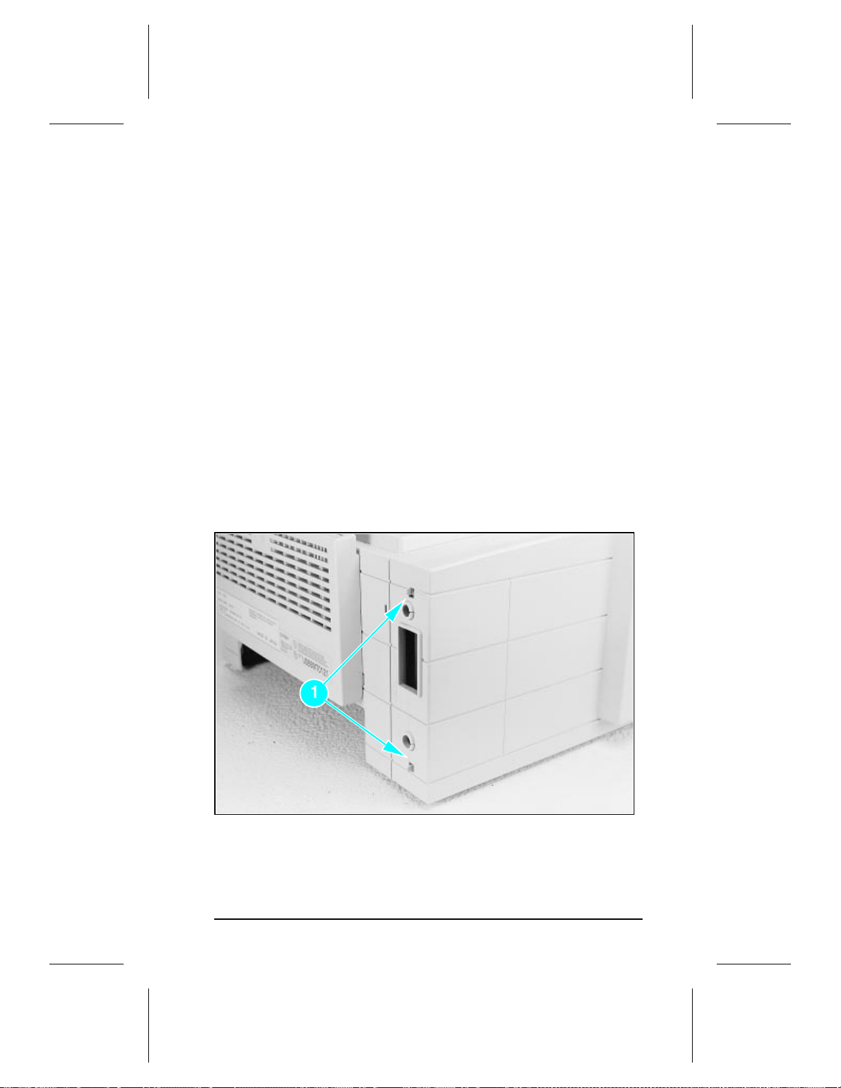
Removing the I/O Cover
The I/O Cover is located to the left rear of the printer.
1. Locate the two release tabs shown in Figure 13. Press the tabs
in, and swing the rear of the door out and forward. The door
easily lifts away from the printer.
Figure 13 I/O Cover Release Tabs
39
Page 47
HP LaserJet 5P Printer Service Supplement
Removal and Replacement
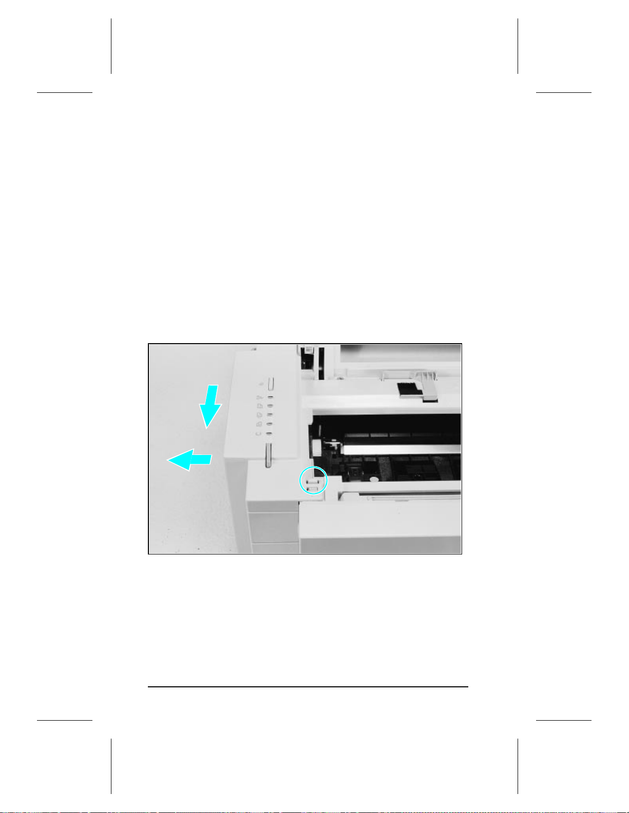
Removing the Left Side Cover
1. Disconnect all I/O cables.
2. Press the To p Co ver Release button on the right side of the
printer, and open the top cover.
3. Press the removable side panel rele ase latch show n in
Figure 14.
4. Slide the cover forward and pull straight away from the side of
the printer.
Figure 14 Left Side Cover Release Latch
40
Page 48

HP LaserJet 5P Printer Service Supplement
Removal and Replacement
Removing the Top Cover
1. Remove the toner cartridge and paper cassette if they have not
already been removed.
2. Remove the (4) self-tapping printer cover screws (Figure 15).
Figure 15 Removing the Top Cover Screws
3. Grasp the lower left front corner of the top cover, and lift it
forward and up.
4. Grasp the lower portion of the right front cover, and pull
forward and up.
5. At the rear of the printer, lower the face-up output tray.
41
Page 49
HP LaserJet 5P Printer Service Supplement
Removal and Replacement
6. Lift the rear of the printer slightly. Gr asp the lower right back
corner. With your thumbs, flex the plastic towar d you, up, and
out. Figure 16 shows this process for the rear right corner.
Repeat the process for the left rear corner.
Note
Note the position of the ta bs and the catc he s
carefully. This step may require considerable
twisting and flexing of the plastic in order to free
the release tabs.
Figure 16 Releasing the Back Corner of the Top Co v er.
7. Lift the printer cover straight up.
42
Page 50

HP LaserJet 5P Printer Service Supplement
Removal and Replacement
Replacement
Note
When reseating the top cover onto the printer
frame, ensure the black paper-out flag in front
of Tray 1 is seated in the gr oov e of the Tra y 1 lift
plate. If not in the groove, it can easily break
when the cover is forced into place. Re fer to
Figure 17
Figure 17 Paper-Out Flag
43
Page 51
HP LaserJet 5P Printer Service Supplement
Removal and Replacement
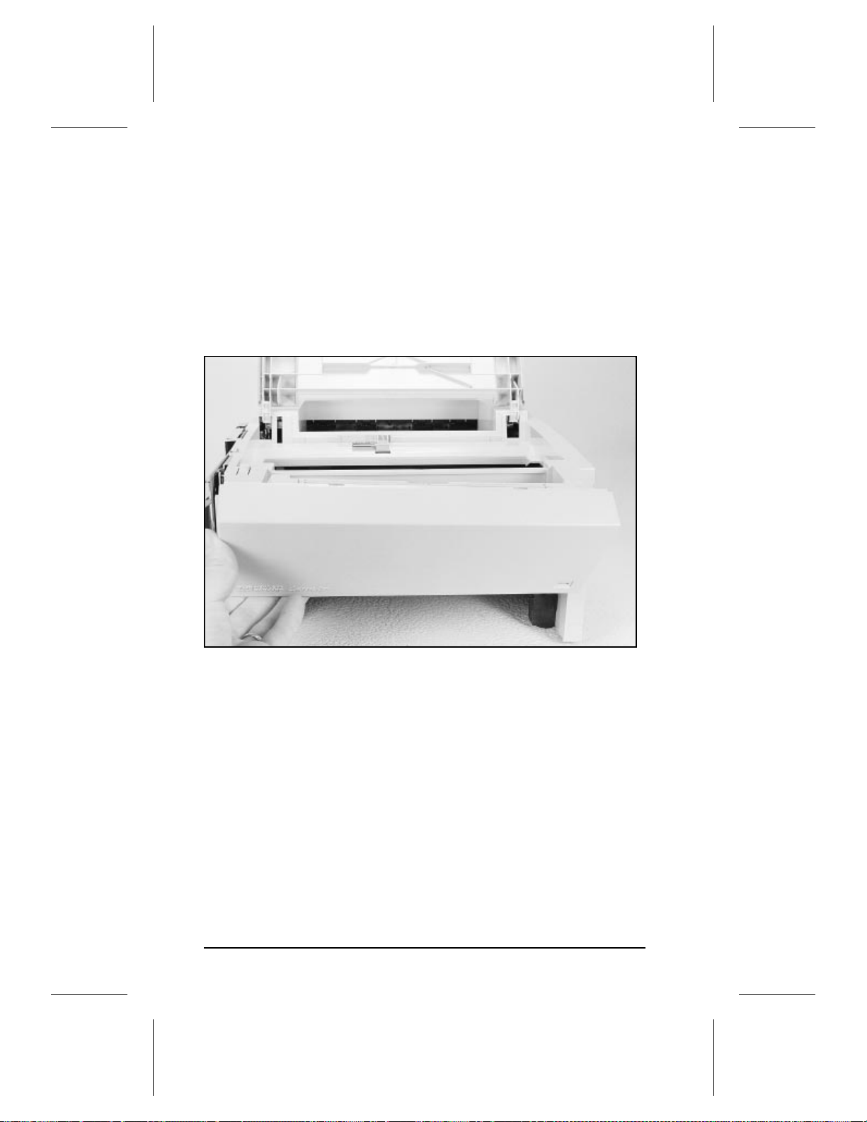
Removing the Tray 1 Pickup Assembly
1. Remove Tray 1 by opening the tray at a 45° angle and pulling
up on the tray (Figure 18).
Figure 18 Removing Tray 1.
2. Unplug the two cables (Callout 2 in Figur e 19) by grasping the
cables where they attach to the plug and pulling straight back.
3. Route the cables through the right side of the printer chass is
and bring them to the front.
4. Remove the 5 screws (callout 1 in Figure 19) from the front of
the pickup assembly. (Two screws are adjac ent in the lower left
corner.)
44
Page 52

HP LaserJet 5P Printer Service Supplement
Removal and Replacement
Figure 19 Tray 1 Pickup Assembly Locations.
5. Press the two release tabs on either side of the pickup assembly
(callout 3 in Figure 19) and pull the assemb ly away fr om the
printer. (The left side re le ase tab is partially hid d en from vie w.
Pressing in on both sides will release the tabs.)
6. Pull the pickup assembly straight out from the back of the
printer.
7. To remove the roller from the pickup assembly, grasp the tabs
on the right end of the roller and slide it to the right (sho wn in
Figure 20).
45
Page 53

HP LaserJet 5P Printer Service Supplement
Removal and Replacement
Figure 20 Replacing the Pickup Rol ler
Replacement
Note
When replacing the pickup assembly roller, hold
the shaft from the left side so that the pickup
roller shaft and gears will remain in place.
46
Page 54
HP LaserJet 5P Printer Service Supplement
Removal and Replacement
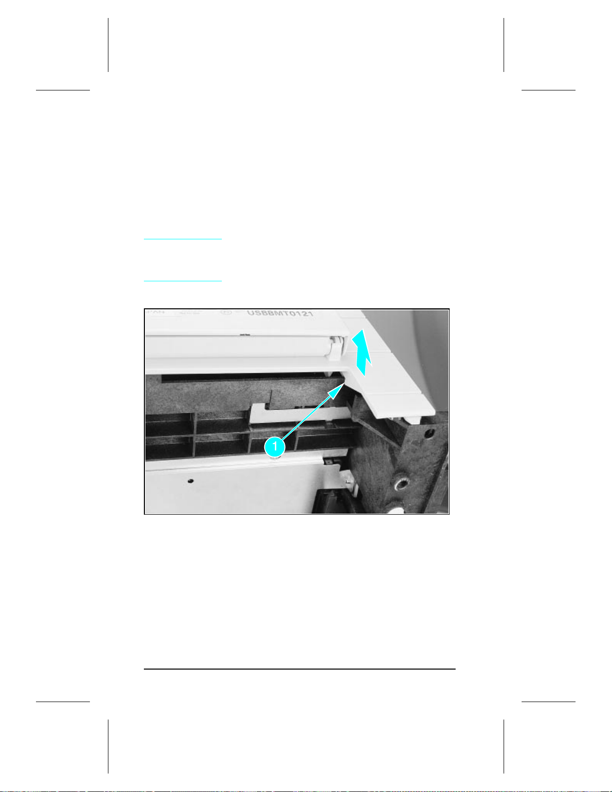
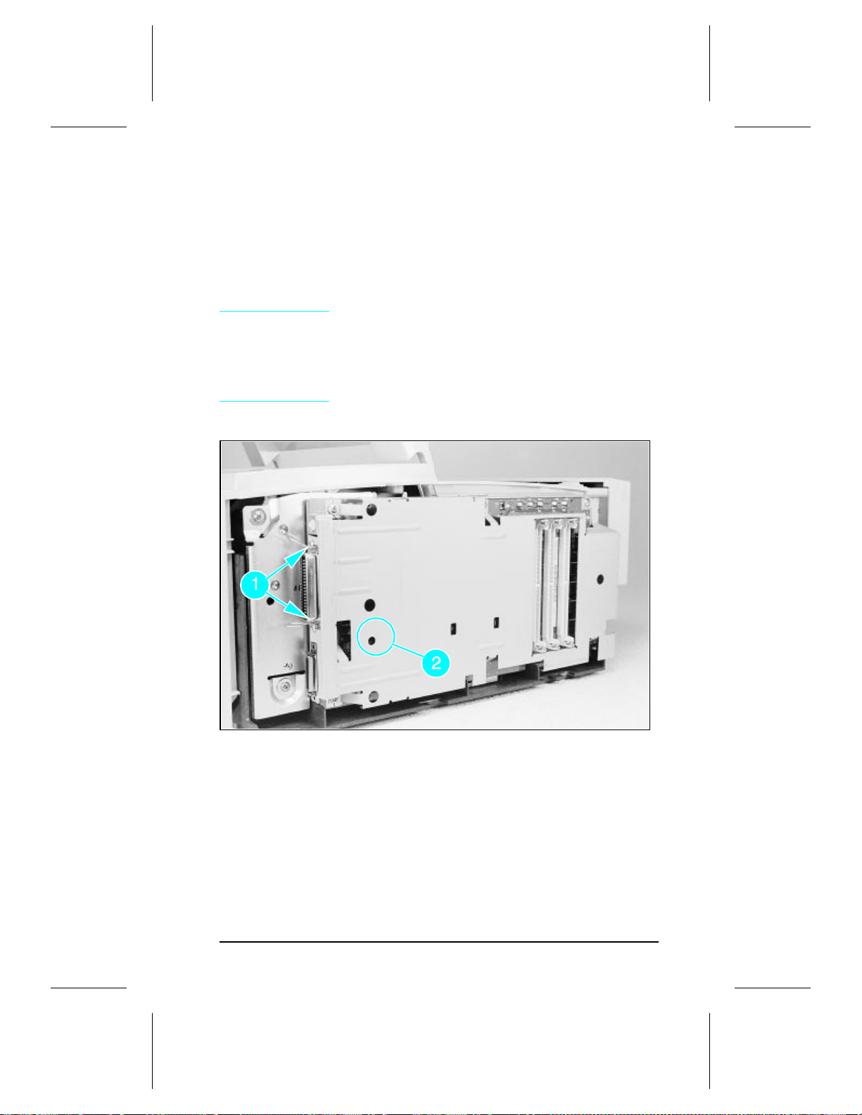
Removing the Formatter Boa rd and Sh ield
1. Remove any installed SIMMs.
Note
There are two TORX screws holding the I/O
connector in position ( Callo ut 1 in Figure 21).
These are the only two TORX screws in the HP
LaserJet 5P printer. Note also the lo c atio n of
the test print button ho le (Callout 2 ) on the sid e
of the formatte r board cover.
Figure 21 TORX Screw Locations.
47
Page 55

HP LaserJet 5P Printer Service Supplement
Removal and Replacement
Figure 22 Removing the formatter screws.
2. Remove the (7) screws shown in Figur e 22.
3. Pull the formatter board straight from the side of the chassis.
(There will be a slight resistance from the DC Con trolle r
interconnect.)
4. Pull the DC controller interconnect out (Figure 23).
5.5. To separate the formatter PCA from its shield, remove the tw o
screws (refer to callout 1 in Figure 21).
48
Page 56

HP LaserJet 5P Printer Service Supplement
Removal and Replacement
Figure 23 Removing the DC Controller Interconnect.
Note
RETAIN THE DC CONTROLLER
INTERCONNECT when replacing the DC
Controller Bo ard. The replacement board part
number does not include this interconnect.
49
Page 57
HP LaserJet 5P Printer Service Supplement
Removal and Replacement
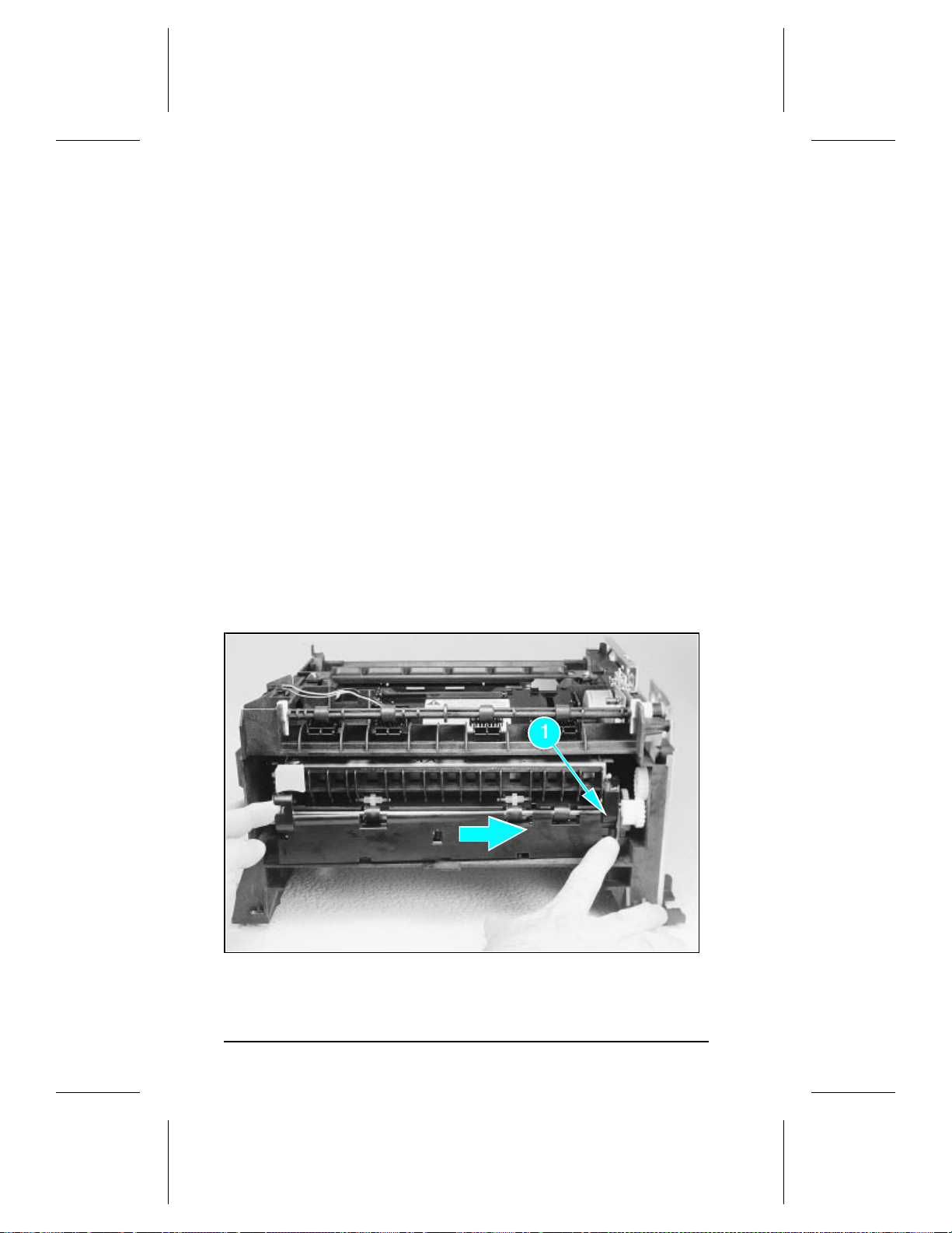
Removing the Fusing Assembly
1. Remove the top cover assemblies.
2. Locate the black plas tic f use r cover at the bac k of the print er.
Press the release tab (callout 1 in Figure 24).
3. Slide the cover all the way to the right.
4. Pull the left end of the strip toward you at a 45° angle.
5. Slide the cover to the left and out of the printer.
6. Remove the four screws (2 self-tapping screws, two machine
screws with washers) directly below the fuser assembly.
7. Grasp the fuser by the green plastic handle and pull out from
the printer.
Figure 24 Removing the fuser cover.
50
Page 58

HP LaserJet 5P Printer Service Supplement
Removal and Replacement
Removing the DC Contro ller Asse mb lies
The DC Controller Assembly is located on the bottom of the
printer. The PCA is protected by a metal shield assembly, and is
mounted to a plastic base. The Formatter PCA and Fusing
Assemblies are connected directly into the DC Contr olle r and must
be removed prior to removal of the DC Controller Assembly.
Caution
1. Remove the printer cove r s (p age 39), For matter PCA and Shield
(page 48), and Fusing Assemblies (page 50).
2. On the right side, remove the machine screw and washer
(Figure 25) holding the grounding spring in place. (Callout 1 in
Figure 25).
3. Disconnect the two cables to the tray 1 assembly (callout 2 in
Figure 25).
Failure to remove these components before
removing the DC Controller will result in
printer damage.
51
Page 59

HP LaserJet 5P Printer Service Supplement
Removal and Replacement
Figure 25 Grounding Spring screw location.
4. On the left side, remove the (2) screws that attach the
grounding strap to the Gear Train Assembly (see callout 1 in
Figure 6-36 of the Combined Service Manual). Turn the
assembly upside-down before proceeding with further steps.
5. Remove the (5) self-tapping screws and the (1) machine screw
with star washer from the bottom of the DC Controller
Assembly. (See callouts 2 and 3 in Figure 6-36 in the Combined
Service Manual.)
6. Lift the DC Controller Ass em bly away fr om the pr inte r fr ame .
52
Page 60

HP LaserJet 5P Printer Service Supplement
Removal and Replacement
Note
7. Remove the metal backing plate from the DC Controller
Assembly (see pages 6-43 and 6-44 in the Combined Service
Manual for this procedure.)
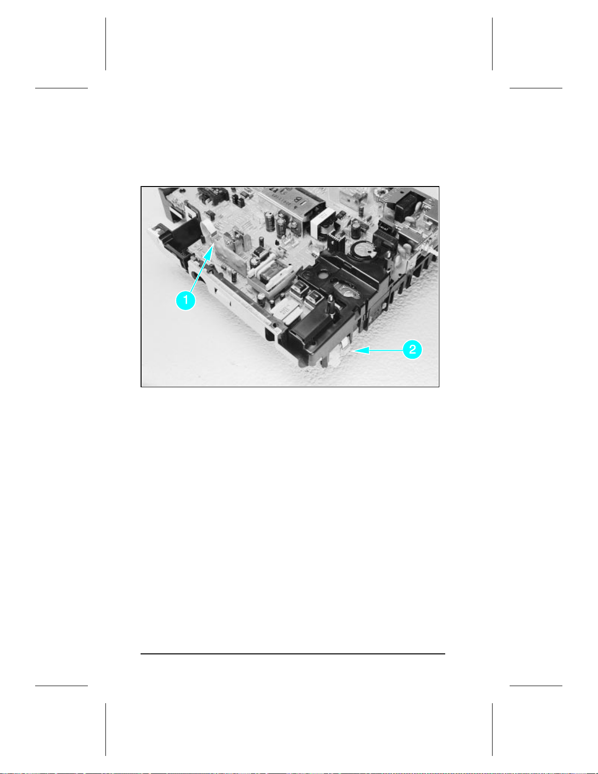
8. Disconnect Tray 1 Interconnect PCA (callout 2 in Figure 26)
and cable 302 (callout 1 in Figure 26) from the DC Contr oller
PCA.
Caution
Note
The PS1 Input Sensor Arm may come loose and
fall out when you remove the DC Controller
Assembly. See Figure 6-51 in the Combined
Service Manual for re-installation.
Remove the Tray 1 Interconnect PCA carefully;
it can easily be broken when separating it from
the black plastic cover .
The Tray 1 Interconnect PCA and cable must
also be retained when replacing the DC
Controller Bo ard. The part number f or the DC
Controller Bo ar d doe s no t inc l u de a re p lac e me nt
PCA and cable. This cable can be directly pulled
from the connector no releases are necessary.
53
Page 61
HP LaserJet 5P Printer Service Supplement
Removal and Replacement
Figure 26 Tray 1 Interconnect PCA and Cable 302
54
Page 62

HP LaserJet 5P Printer Service Supplement
Troubleshooting
Troubleshooting
The troubleshooting process for the HP LaserJet 5P/5M P print er
has two key differences from the 4L/4ML printer:
• Different error light patterns (5 LEDs instead of 4).
• Infrared port troubleshooting.
This section provides a list and explanation of the error LED
patterns and instructions on troublesho oting the infrare d port
55
Page 63

HP LaserJet 5P Printer Service Supplement
Troubleshooting
Continuable Data Error Light Patterns
Possible data error light patterns are listed in the first column of
the following table. If the Error and Data lights on the Status
Panel are lit, simultaneously press the GO and RESET butt ons on
the printer to display a secondary light pattern. This secondary
light pattern, or data error light pattern, will more precisely
describe the problem. Where more than one data error light
pattern is possible, corresponding computer messages are listed in
the second column.
Data Error
Light Pattern
Computer
Message
20 MEM
OVERFLOW
21 PRINT
OVERRUN
22 IO ERROR
Description Recommended
Action
Too much data, or data
too complex.
The computer and printer
are not communicating
because of improper
signal protocols. Indicates
a loose cable connection
or a bad or poor quality
cable.
Turn Page Protection ON
or to AUTO (can be set
within the Remote Control
Panel).
2. Add optional memory.
3. Reduce the complexity
of the print job.
Press GO to resume
printing.
Reseat the cable and
make sure you are using
a high-quality cable
56
Page 64

HP LaserJet 5P Printer Service Supplement
Troubleshooting
Data Error
Light Pattern
Computer
Message
40 ERROR
41 ERROR
51/52 ERROR
55 ERROR
Description Recommended
Action
Indicates an abnormal
connection break
occurred while
transferring data from the
computer.
A temporary error
occurred while printing.
This error most commonly
occurs when the printer
picks two sheets of paper
at once. The page
containing the error is
reprinted automatically.
(first two light sequences)
(first and second light
sequence)The printer
detected a temporary
error condition.
(third light sequence)
The printer detected a
temporary error condition
Press GO on the printer
to clear the error
message.
Remove the page from
the output tray and press
GO on the printer
Turn the printer off then
on. If the problem persists
replace the laser scanner
assembly.
Turn the printer off then
back on. If problem
persists, replace the DC
Controller. If the problem
still continues, replace the
formatter PCA.
68 SERVICE
or 68
READY/SERVICE
The printer’s nonvolatile
memory (NVRAM) is full.
Press GO on the printer
to clear the error
message. If problem
persists,
1. Perform NVRAM
Reset to clear NVRAM
(hold down the RESET
button for more than 20
seconds during power on.
2. Replace the formatter
PCA.
57
Page 65

HP LaserJet 5P Printer Service Supplement
Troubleshooting
Error 53 -- Memory/SIMM Erro rs
Error 53 is indicated by a combination of the Error LED and either
Tray LED, on and steady. More detail about the error is found by
pressing the GO and RESET buttons simultaneous ly, which cause s
a secondary sequence of light patterns. These secondary patterns
form a binary representation of the exact hard ware type, device
and error number in the form 53-XY-ZZ as shown in Table 4.
Table 4.
X-Hardware
Type
Memory Error Codes
Y-Hardware Device ZZ - Error Number
0: ROM 0: On board RAM/ROM 00: Unsupported memory
1: RAM 1: SIMM slot 1 01: Unrecognized memory
2: SIMM slot 2 03: Unsupported memory size
3: SIMM slot 3 04: Invalid SI MM speed
05: SIMM reporting information
incorrectly
06: SIMM address conflict
07: SIMM address conflict
Figure 27 explains how to read the light sequences. The initial
sequence (Part 1) shows that ERROR 53 can be indicated by two
different light sequences, depending on the X value: ROM (x =0) or
in RAM (x =1) . Pressing GO and RESET together produces a
secondary light patter n, which reveals the Y- and ZZ- values ,
which complete the error code (Part II) . The binary Y value is read
from the top two LEDS; the binary Z value is read from the lower
three LEDS. Part III of Figure 27 shows the binary values of the
different light combinations.
58
Page 66

HP LaserJet 5P Printer Service Supplement
Troubleshooting
Figure -27 Secondary Light Patterns
59
Page 67

HP LaserJet 5P Printer Service Supplement
Troubleshooting
Fatal/Service Erro rs
The following tables show fatal/service errors, which are not
continuable; no further operation of the printer will occur until
corrective action is taken.
Table 5. Fuser Malfunction
LED Display ERROR CODE Description and Recommendation
50 Fuser Malfunction
1. Remove power to the printer for 10 minutes.
If this doesn’t clear the error:
2. Perform the Fuser Checks shown in Table
C-6.
3. Check the Fuses (FU101 and FU201) on the
DC Controller PCA. Replace if faulty.
3. Replace the DC Controller PCA.
Table 6. Fuser Checks
SUSPECTED CAUSE CHECK
1. Connector Contact Ensure that J103 and J204 connectors on the Fusing Assembly are seated
2. Thermistor wire open. Remove the Fuser and measure the resistance between connectors J204-1
3. Thermal Fuse. Measure the continuity between connectors J103-1 and J103-2 on the Fuser
securely into the DC Controller PCA connectors (see Figure 6-29 in the
Combined Service Manual for locations). Reseat the Fusing Assembly.
and J204-2 (see Figure 6-29 in the Combined Service Manual for location).
Resistance should read approximately 440 K Ohms at 20 Deg C (room
temperature). If the thermistor wire is open, replace the Fusing Assembly.
(see Figure 6-29, the Combined Service Manual for location). It should be
approximately 30±5 Ohms for 100-120 VAC or 127±5 Ohms for 220-245
VAC. If the thermal fuse is open, replace the Fusing Assembly.
60
Page 68

HP LaserJet 5P Printer Service Supplement
Troubleshooting
Table 7. 57/58 Main Motor Failure
LED Display ERROR CODE Description and Recommendation
57/58 Main Motor Failure
The DC Controller has reported a
general motor failure. The Main Motor
is controlled by the DC Controller
PCA, and seated into connector J601.
Power-cycle the printer. If this doesn’t
clear the message:
1. Does the main motor rotate on
power-up? If no:
a. Reseat the Main Motor into the DC
Controller connector.
b. Inspect the Gear Train for debris
that would block the free operation of
the gears.
c. The toner cartridge may not be
rotating. Refer to "Drum Rotation
Functional Check in the Combined
Service Manual.
d. Main Motor faulty. Power up the
printer and observe if stacker rollers
rotate. If not, replace the Main Motor.
e. Replace the DC Controller PCA.
If the main motor does rotate:
2. Does the fan turn during printing?
If no:
a. Power-cycle the printer.
b. Check the fan to determine if it is
blocked from operation.
c. Reseat the fan connector on the
Laser/Scanner Assembly.
d. Replace the Fan.
e. Replace the Laser/Scanner
Assembly.
f. Replace the DC Controller.
g. Replace the connector between the
scanner and DC Controller.
61
Page 69

HP LaserJet 5P Printer Service Supplement
Troubleshooting
Table 8. 61.x/62.x SIMM Parity and Memory Errors
LED Display ERROR CODE
61.1 SIMM Slot One
Parity Error
62.1 SIMM Slot One
Memory Problem
61.2 SIMM Slot Two
Parity Error
62.2 SIMM Slot Two
Memory Problem
61.3 SIMM Slot Three
Parity Error
62.3 SIMM Slot Three
Memory Problem
Description and
Recommendation
1. Power-cycle the printer.
2. Reseat the SIMM.
3. Replace the SIMM.
62
Page 70

HP LaserJet 5P Printer Service Supplement
Troubleshooting
Table 9. 62/63/64 Internal Memory Error
LED Display ERROR CODE Description and Recommendation
62.0 Internal Memory
Problem
63 Internal RAM Memory Test Failed
64 Scan Buffer Error
1. Power-cycle the printer.
2. Replace the Formatter PCA.
63
Page 71

HP LaserJet 5P Printer Service Supplement
Troubleshooting
Table 10. Video DMA Timeout Error
LED Display ERROR CODE Description and Recommendation
64 ERROR:
Video DMA Timeout
1. Power-cycle the printer.
2. Replace the Formatter PCA.
Table 11. Dynamic RAM Controller Error
LED Display ERROR CODE Description and Recommendation
65 ERROR:
Dynamic RAM Controller
1. Power-cycle the printer.
2. Replace the Formatter PCA.
‘
64
Page 72

HP LaserJet 5P Printer Service Supplement
Troubleshooting
Infrared Port Not Responding
Situation Solution
The connection cannot be established or the transmission seems
to be taking longer than usual.
The printer prints only part of a
page or document.
Make sure the device you are using is IrDAcompliant; look for an IrDA symbol on the
device or refer to the manual for the device for
IrDA specifications.
Make sure that the operating system on your
computer includes an IR driver and your
application uses a HP LaserJet 5P/5MP
compatible printer driver.
Make sure you have positioned the device
within the range of operation and that no
objects, such as a finger, paper, books, or
bright light, are interfering with the connection.
Also make sure the two IR ports are clean (free
from dirt and grease).
Bright light of any kind (sunlight, incandescent
light, fluorescent light, or light from an infrared
remote control, such as those used for TVs and
VCRs) shining directly into one of the IR ports
may cause interference.
Position the device closer to the IR port on the
printer.
The connection has been broken during
transmission. If you move the portable device
during transmission, the connection can be
broken. IrDA-compliant devices are designed to
recover from temporary connection
interruptions. Re-establish the connection
(depending on the device you are using, you
can have anywhere from 3 to 40 seconds to reestablish the connection).
65
Page 73

HP LaserJet 5P Printer Service Supplement
Troubleshooting
Situation Solution
The print job has been properly
sent to the printer, but the printer
will not print.
If the connection is broken before the entire
print job has been transmitted to the printer
(printing has not yet started), the printer may
not print any of the job. If the Data lig ht is on,
press the RESET button to clear the printer’s
memory. Then, position the device within t he
range of operation, and print the job again.
The IR status light turns off during
transmission.
The connection may have been broken. If the
Data light is on, press the RESET button to
clear the printer’s memory. Then, position the
device within the range of operation, and print
the job again.
Using the Infrared Test Tool
A special infrared troubleshooting test tool manufactured by
Genoa Technolo gy , Inc . in cooper at ion with H ewle tt-Pac k ar d is
available through HP Direct Ordering (part number 5062-4461).
Refer to the discuss ion begin ning on pag e 22 for mor e inf o rmatio n.
66
Page 74

HP LaserJet 5P Printer Service Supplement
Troubleshooting
Sensor
Infrared
SL2
Solenoid
Input Paper
Sensor PS5
Tray 1 Paper Out
Tray 1 Pickup Assembly
TO FRONT OF PRINTER
Tray 1
Inter-connect
PCA
AA
SL1
Tray 2 Solenoid
J301
J302
AA
Adjust
VR301
Registration
Sensor PS1
Circuitry
High Voltage
Power Supply
J402
J201
J207
SW201
Sensor PS2
Tray 2 Paper Out
J403
J404
Sensor PS4
Winding Paper
J401
J202
DC Power
Supply Circuitry
FU201
AC Power
Supply Circuitry
J101
J601
FU101
J204
Exit Paper
Sensor PS3
J103
SW301
Engine Test
Figure 28 Main Wiring Diagram
67
Page 75

HP LaserJet 5P Printer Service Supplement
Parts and Diagrams
Parts and Diagrams
The figures in this section illustrate th e major subass em blies i n
the printer and their c omp o ne nt part s. A table ( mate rial list )
follows each exploded assembly d iagram. Eac h table lists the
reference designator (item number) for each part, the associated
part number for the item, the quantity, and a description of the
part.
While looking for a part number, pay care ful att entio n to the
voltage listed in the descrip tio n c olum n to ensur e that the part
number selected is for the correct model of printer.
Ordering Parts
All standard part numbers listed are stocked and may be ordered
from HP’s Parts Direct Ordering, or Parts Center Europe (PCE).
Hewlett-Packard Co.
Support Materials Orga nization
8050 Foothills Blvd.
Roseville, CA 95678
Parts Direct Ordering: 1-80 0-227-8164 (U.S. Only)
Hewlett-Packard Co.
Parts Center, Europe
Wolf-Hirth Strasse 33
D-7030 Boeblingen , Germany
(49 7031) 14-2253
Contact your local HP Parts Coordinator for other local phone
numbers.
68
Page 76

HP LaserJet 5P Printer Service Supplement
Parts and Diagrams
Ordering Consumable s
Consumables and accessorie s such as those listed on page 8-5, and
in Table 4-1, Chapter 4, may be ordered direct from
Hewlett-Packard. The phone numbers are:
U.S.: 1-800-538-8787
Canada: 1-800-387-315 4
(Tor onto) 416-671 -8383
United Kingdom : 0734-4 41212
Germany: 0130-3322
Contact your local HP Part s Co ordinator fo r o the r lo c al p ho ne
numbers.
Note
Parts that have no reference designator or part
number are not field replaceable parts and
cannot be ordered through SMO.
69
Page 77

HP LaserJet 5P Printer Service Supplement
Parts and Diagrams
Figure 29. HP LaserJet 5P Covers and Doors
70
Page 78

HP LaserJet 5P Printer Service Supplement
Parts and Diagrams
Table 12.
Covers and Doors
REF PART NO. QTY DESCRIPTION
1 RG5-1709-000CN 1 Top Door Assembly
2 RG5-1699-000CN 1 Power Connector Cover Assy
3 RB1-5931-000CN 1 Cover, Main
4 RB1-5935-000CN 1 Button, Lock
5 RS5-2228-000CN 1 Spring, Compression
6 RB1-5936-000CN 1 Guide, Lock Button
7 RG5-1697-000CN 1 Paper Feed Tray Assembly
8 RB1-5939-000CN 1 Arm, Tray 1 Sensor
9 C3150-00004
C3155-00001
1 Nameplate (HP LaserJet 5P)
Nameplate (HP LaserJet 5MP)
10 RS5-2418-000CN 1 Spring, Torsion
11 RB1-5937-000CN 1 Stopper, Hinge, Right
12 RB1-5938-000CN 1 Stopper, Hinge, Left
13 RS5-2419-000CN 1 Spring, Torsion
14 RF5-0593-000CN 1 Brush, Mirror
15 RB1-5934-000CN 1 Cover, Interface Connector
16 R G5-1710-000CN 1 Side Cover Assembly
17 RB1-5927-000CN 1 Bushing
18 RB1-5924-000CN 1 Tray, Sub-assy, Face-Up
19 RG5-1707-000CN 1 Face-Up Tray Assembly
71
Page 79

HP LaserJet 5P Printer Service Supplement
Parts and Diagrams
Figure 30. HP LaserJet 5P Internal Components (1)
72
Page 80

HP LaserJet 5P Printer Service Supplement
Parts and Diagrams
Table 13.
Internal Components (1)
REF PART NO. QTY DESCRIPTION
1 RG5-1801-000CN 1 Fan Assembly
2 RB1-6006-000CN 1 Arm, Sensor
3 RB1-6332-000CN 1 Pick-Up Roller (tray 2)
4 RG5-1692-000CN Pick-Up Assy (tray 2)
5 RG5-1799-000CN 1 Motor Assembly
6 C3150-00005 1 Formatter Shield
7 C3152-69001 1 PostScript SIMM (exch.)
8 C3151-67901
C3151-69001
1 Formatter PCA (new)
Formatter PCA (exch.)
9 0515-2701 2 TORX screws
10 RB1-5971-000CN 1 Leaf Spring
11 RG5-1713-000CN 1 Gear train Assembly
12 RB1-5999-000CN 1 Plate, Grounding, Left
13 RB1-5998-000CN 1 Plate, Grounding, Right
73
Page 81

HP LaserJet 5P Printer Service Supplement
Parts and Diagrams
Figure 31. HP LaserJet 5P Internal Components (2)
74
Page 82

HP LaserJet 5P Printer Service Supplement
Parts and Diagrams
Table 14.
Internal Components (2)
REF PART NO. QTY DESCRIPTION
1 RG5-0683-020CN 1 Roller, Upper Output Assembly
2 XA9-0666-000CN 2 Screw, TP
3 RG5-1786-000CN 1 Mirror Assembly
4 RB1-5873-000CN 1 Roller, Transfer
5 RS5-0313-000CN 1 Gear, 17T
5a RF5-1287-000CN 1 Transfer Roller Assembly
6 RG5-1706-000CN 1 Transfer Guide Assembly
7 RG5-0675-000CN 1 Transfer Mount Assy, Right
8 RG5-0674-000CN 1 Transfer Mount Assy, Left
9 RG5-0694-020CN 1 Switch, Plunger Assembly
10 RG5-0766-030CN 1 Scanner Connector Assy
11 RG5-0682-030CN 4 Lower Delivery Roller
75
Page 83

HP LaserJet 5P Printer Service Supplement
Parts and Diagrams
Figure - 32. HP LaserJet 5P Internal Components (3)
76
Page 84

HP LaserJet 5P Printer Service Supplement
Parts and Diagrams
Table 15.
Internal Components (3)
REF PART NO. QTY DESCRIPTION
1 RG5-1780-000CN
C3150-69005
1 Laser Scanner Assembly (new)
Laser Scanner Assembly (exch.)
2 RG5-1698-000CN 1 Top Oblique Roller Assy
3 RB1-3002-040CN 1 Plunger Lock, Door
4 RS5-2232-000CN 1 Spring, Compression
5 RB1-6003-000CN 1 Plate, Cartridge
6 RB1-6002-000CN 1 Plate, Cartridge Grounding
7 RF5-1286-000CN 1 Plate, MP Grounding, Right
8 RB1-6001-000CN 1 Arm, Input Paper Sensor
9 RB1-2987-020CN 1 Shield, HVT
10 RG5-0584-000CN 1 Feeder Guide Assembly
11 RF5-1283-000CN 1 Eliminator, Static Charge
12 RG5-1814-000CN 1 Roller Assembly, Small Media
13 RB1-6007-000CN 4 Foot, Chassis
14 RB1-6008-000CN 6 Damper, Rubber
15 RB1-3681-000CN 1 Cap, Laser Shutter
77
Page 85
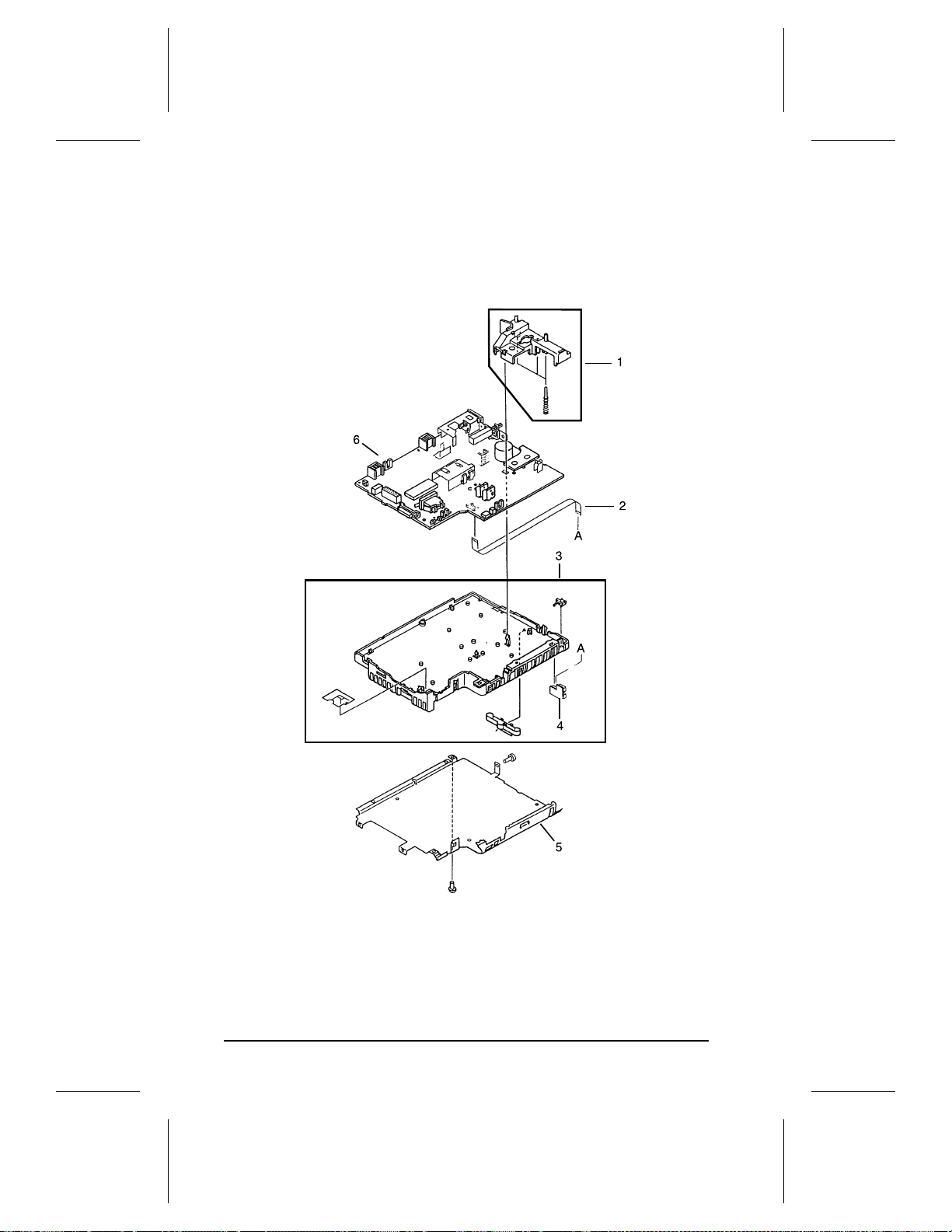
HP LaserJet 5P Printer Service Supplement
Parts and Diagrams
Figure 33. DC Control ler Assemb l y
78
Page 86

HP LaserJet 5P Printer Service Supplement
Parts and Diagrams
Table 16.
DC Controller Assemb ly
REF PART NO. QTY DESCRIPTION
1 RG5-1719-000CN 1 HVT Controller Assembly
2 RH2-5259-000CN 1 Cable, Flat
3 RG5-1712-000CN 1 DC Controller Case Assy
4 RG5-1808-000CN 1 Tray 1 Connector PCA Assy
5 RB1-5987-000CN 1 Shield, Case
6
RG5-1798-000CN
C3150-69001
1 DC Controller PCA (100-120V)
(new)
(exchange)
DC Controller PCA (220-240V)
RG5-1809-000CN
C3150-69002
(new)
(exchange)
79
Page 87

HP LaserJet 5P Printer Service Supplement
Parts and Diagrams
Figure 34. Tray 2 Assembly
80
Page 88

HP LaserJet 5P Printer Service Supplement
Parts and Diagrams
Table 17.
Tray 2 Assembly
REF PART NO. QTY DESCRIPTION
R75-4000-000CN 1 Complete Tray 2 Assembly
1 RF5-0673-000CN 1 Plate, Side
2 RS5-2458-000CN 1 Spring, Compression
3 RB1-3426-000CN 1 Claw, Separation
4 RB1-6378-000CN 1 Tray, Legal
5 RB1-3338-000CN 1 Plate, End
81
Page 89

HP LaserJet 5P Printer Service Supplement
Parts and Diagrams
Figure 35. Tray 1 Assembly
82
Page 90

HP LaserJet 5P Printer Service Supplement
Parts and Diagrams
Table 18.
Tray 1 Assembly
REF PART NO. QTY DESC
RG5-1695-000CN 1 Complete Tray 1 Pickup Assy
1 RG5-1804-000CN 1 Tray 1 Sensor Cable
2 RG5-1694-000CN 1 Paper guide Plate Assy
3 RS5-2415-000CN 1 Spring, Compression
4 RH7-1258-000CN 1 Solenoid SL2
5 RG5-1693-000CN 1 Tray 1 Pickup Roller Assy
6 RB1-2205-000CN 1 Roller, Tray 1 Pickup
7 RF5-0343-000CN 1 Pad, Separation
8 WG8-5210-000CN 1 Photosensor PS5
83
Page 91

HP LaserJet 5P Printer Service Supplement
Parts and Diagrams
Figure 36. HP LaserJet 5P Fusing Assembly
84
Page 92
HP LaserJet 5P Printer Service Supplement
Parts and Diagrams
Table 19.
Fusing Assembly
REF PART NO. QTY DESCRIPTION
1
Complete Fuser Assy (100-120V)
RG5-1700-000CN
C3150-69003
RG5-1701-000CN
C3150-69004
(new)
(exchange)
1
Complete Fuser Assy (220-240V)
(new)
(exchange)
1 RB1-5918-000CN 1 Cover, Delivery
2 RB1-3097-000CN 1 Flag, Exit Sensor
3 RG5-0681-000CN 1 Fuser Delivery Assembly
4 RG5-1813-000CN 1 Guide , Fuser Entrance
5 XB2-8300-809CN 2 Screw, W/Star, M3X8
6 RS5-2421-000CN 1 Spring, Tension
7 RS5-0637-000CN 1 Gear, 24T
8 RB1-3109-000CN 1 Rubber, Continuity
9 RS5-2421-000CN 1 Spring, Fuser Hook
10 RB1-5910-000CN 1 Roller, Fuser Pressure
11 RG5-1702-000CN
RG5-1703-000CN
1 Fuser Film Assembly (100-120v)
Fuser Film Assembly (220-240V)
12 RB1-5917-000CN 1 Roller, Fuser Delivery
13 RB1-5906-000CN 1 Tab, Fuser Release
85
Page 93

HP LaserJet 5P Printer Service Supplement
Accessories
Accessories
Listed below are the accessories and supplies, including
supplemental documentation you can orde r for your H P Laser Jet
5P or 5MP printer.
Option Part Number Description or Use
Toner Cartridge C3903A Replacement toner cartridge.
Memory upgrades 1 MByte—C3130A
Adobe’s PostScript Level 2
SIMM for the HP LaserJet
5P
IEEE-1284 Parallel Cable 2 Meter A to B—C2950A
LocalTalk Network cable
for Macintosh
Serial printer cable for
Macintosh
HP JetDirect EX print
servers (external)
HP Printer Pal (external) C2971A Printer fax accessory. Allows faxes to be printed by the
Extra Paper Cassette (Tray
2)*
IrDA Test Tool 5062-4661 Infrared communications test tool manufactured by Genoa
2 MByte—C3131A
4 MByte—C3132A
8 MByte—C3133A
16 MByte—C3146A
C3152A Adds PostScript Level 2 language and 1 MByte of memory
3 Meter A to B—C2951A
3 Meter A to C—C2946A
10 Meter A to C—C2947A
92215N Connect to a LocalTalk Network.
92215S Directly connect to a Macintosh computer.
J2382B
J2383B
J2593A
J2594A
R75-4000-000CN Universal tray.
Adds up to 48 MBytes of memory to the HP LaserJet 5P
printer, for a total of 50 MBytes. Adds up to 32 MBytes of
memory to the HP LaserJet 5MP printer, for a total of 35
MBytes.
to the HP LaserJet 5P printer; includes software for
Macintosh, Windows 3.1 and 3.11, and “HP LaserJet 5MP
Macintosh Notes” (factory-installed in the 5MP printer).
IEEE-1284-compliant cables, where:
A=host computer connector (A-type)
B=large printer connector (B-type)
C=small printer connector (C-type)
Ethernet (1 parallel ports)
TokenRing (1 parallel ports)
Ethernet (3 parallel ports)
TokenRing (3 parallel ports)
printer; faxes can also be sent electronically from the PC.
Availability outside the US may vary.
Technologies, Inc.
* This item must be ordered through HP Parts Direct Ordering, (800) 227-
8164. Outside the U.S., see "Parts and Diagrams earlier in this appendix.
86
Page 94

Index
!
20 MEM OVERFLOW 56
21 PRINT OVERRUN 56
22 IO ERROR 56
40 ERROR 57
41 ERROR 57
50 FUSER ERROR 60
51 ERROR 57
52 ERROR 57
55 ERROR 57
57/58 MOTOR ERROR 61
61.x SIMM ERROR 62
62 MEMORY ERROR 63
62.x SIMM ERROR 62
63 MEMORY ERROR 63
64 ERROR 64
64 SCANNER ERROR 63
65 ERROR 64
68 SERVICE ERROR 57
A
accessories 86
automatic I/O switching 26
B
bi-directional communication 26
books available 8 -9
buttons
GO 10
power 4
RESET 10
status panel 10
C
cables
IEEE-1284 compliant 26
clearing memory with RESET 10
cold reset 30
connections
network 26
consumables
life 36
ordering 69
D
data light 12
DC controller 78
interconnect 49
removal and replacement 51
default settings, returning to 11
demo page 10, 30, 33
diagnostic 30
diagrams
covers and doors 70
DC controller 78
fusing assembly 84
internal components 72, 74, 76
printer parts 4
tray 1 assembly 82
tray 2 assembly 80
wiring 67
DMO 69
documentation 8 -9
drivers 9
E
Economode 3
erasing memory with RESET 11
error
clearing with RESET 11
continuable 56
data 14
fatal 15, 60
hardware-related 11
infrared 65
IR port 15
light patterns 56
memory 58
recoverable 14
secondary 56
service 60
SIMM 14, 58
error light 11, 14
F
fax accessory 86
features 10 -29
product information 3
flashing lights 11
fonts 3
temporary, removing with RESET 11
formatter
removal and replacement 47
fusing assembly 84
removal and replacement 50
G
GO button 10, 32, 56
grounding 25
I
I/O buffering 28
I/O cover
removal and replacement 39
I/O switching 26
IEEE-1284
B-Type, C-Type 25, 26
1
Page 95

cables, compliant 26
parallel ports 25 -26
specifications 26
infrared
communication 18
interface 3
operation 21
port 4, 10
printing 20
software 18
status light 4, 10, 12, 15, 20
test tool 22, 23, 66, 86
troubleshooting 22, 65, 66
using to print 20
interface cables 25 -26
interfaces 25
I/O switching 26
internal components 72, 74, 76
IrDA, print using 20
J
JetDirect 86
L
LED
patterns 58
LED
patterns 56
LED patterns 13
LEDs, status 11
left side cover
removal and replacement 40
light
patterns 13, 56, 58
lights on status panel
described 11
lights, status 11
LocalTalk interface 3
LocalTalk port 25
M
Macintosh
reference manual available 8 -9
macros, temporary 11
main wiring diagram 67
media path 16 -17
memory 3
and I/O buffering 28
and resource saving 27
clearing with RESET 11
error 58, 62
ordering 86
SIMM removal 39
model number 5
monthly usage 3
N
network, connecting to 26
networks 26
NVRAM 32
O
ordering
books 8 -9
consumables 69
LocalTalk 86
parts 68
Postscript 86
P
pages, self-test 10, 33
panel
See status panel
paper
jams 11
movement, overview (theory) 16
path 16 -17
size 3
specifications 8 -9
trays 3, 4, 86
paper-out flag 43
parallel cable 26
parallel interface 3
parallel ports 25
parts
ordering 68, 86
Parts Center Europe (PCE) 68
parts and diagrams 68 -85
parts, location 4, 17
PCE 68
PCL
self-test page 33
phone numbers
DMO 69
ordering consumables 69
PCE 68
SMO 68
PJL commands 30 -35
port
infrared 19
ports 25
PostScript, SIMM removal 39
power door
removal and replacement 39
power switch 4
print speed 3
print spoolers 26
printer
diagram 4
lights 11
parts diagram 4
serial number 5
printer configuration 30
printer languages 3
printer settings
returning to defaults 11
2
Page 96

protocol
infrared 18
R
ready light 12
reference guides 8 -9
regulatory information 5
removal and replacement 37
DC Controller 51
formatter 47
fusing assembly 50
I/O cover 39
left side cover 40
power door 39
tools 38
top cover 41
Tray 1 assembly 44
removing fonts, macros 11
required tools 38
requirements
for in f rared 19
RESET button 10, 32, 56
resetting your printer 11
resolution 3
resource Saving 27
modes 27
resuming printing 10
S
self test 30, 33
self-test
explained 35
pages 10, 33
serial number 4, 5
service mode 30 -35
settings
returning to defaults 11
SIMM
error 14, 58, 62
removal 39
SMO 68
software 19
shipped with printer 9, 18
space requirements 6
specifications
acoustic 7
dimensions 6 -7
electrical 7
environmental 7
IrDA 18
spoolers 26
status panel 3, 4, 10
GO button 10 -11
lights 11
RESET button 10
supplementary documents 8 -9
Support Materials Organization
(SMO) 68
switchboxes 26
switching, I/O 26
T
temporary fonts, macros 11
test pages 10, 32 -33
test tool 66, 86
infrared 23
toner, ordering 86
tools, required 38
top cover
removal and replacement 41
tray
empty 13 -14
tray 1
assembly 82
removal and replacement 44
light 12
tray 2
empty indicator 12
assembly 80
light 12
troubleshooting 55 -67
infrared 22
troubleshooting, IR port 22
turning on your printer 4
typefaces see fonts 3
W
wireless printing
See see infrared
wiring diagram 67
3
Page 97

4
Page 98

HP C3150A Printer Service Manual Reader’s Com m ent Sheet
Please give us your comments concerning this manual. Your constructive criticism will help us create
better manuals in the future. Be as specific as possible, giving section and page reference where
appropriate. Comments on the writing, graphics, binding, size, and printing method are helpful in
making our manuals more useful and friendly.
I you would like a reply, be sure to include your name and address with your response. Thank you for
your feedback.
March 1995
5010-6305
Page 99

© Copyright HewlettPackard Company 1996
All Rights Reserved. Reproduction, adaptation, or
translation without prior
written permission is prohibited, except as allowed
under the copyright laws.
Publication number
C3980-99001
First edition, August 1996
Printed in USA
Warranty
The information contained
in this document is subject
to change without notice.
Hewlett-Packard makes
no warranty of any kind
with regard to this material, including, but not
limited to, the implied
warranties or merchantability and fitness fo r a
particular purpose.
Hewlett-Packard s hall not
be liable for errors contained herein or for incidental or consequential
damaged in connection
with the furnishing, performance, or use of this material.
WARNING
Electrical Shock Hazard
To avoid electrical shock,
use only supplied power
cords and connect only to
properly grounded (3-hole)
wall outlets.
Hewlett-Packard Company
11311 Chinden Boulevard
Boise, Idaho 83714
Page 100

Conventions
This manual uses the following conventions:
Color is used to emphasize items which are important to the material
under discussion.
The names of major printer parts and assemblies are Capitalized.
Bold
is used for emphasis, particularly in situations where
would be confusing.
Italic
type is used to indicate related documents or emphasis.
COMPUTER
Note
CAUTION
WARNING!
type indicates text as seen on a computer monitor.
Notes contain important information set off from
the text.
Caution messages alert you to the possibility of
damage to equipment or loss of data.
Warning messages alert you to the possibility of
personal injury.
italic
type
i
 Loading...