

Page 1
®®
HP
LaserJet 5L/6L/6L Gold/6L Pro
Printer
Service Manual
English
Page 2

Page 3

HP LaserJet 5L/6L/6L Gold/6L Pro Printer
Service Manual _____________
Page 4

© Copyright Hewlett-Packard Company, 2002
All Rights Reserved. Reproduction,
adaptation, or translation without prior written
permission is prohibited, except as allowed
under the copyright laws.
Part number: C8060-90903
Second Edition, February 2002
Warranty
The information contained in this document
is subject to change without notice.
Hewlett-Packard makes no warranty of any
kind with respect to this information.
HEWLETT-PACKARD SPECIFICALLY
DISCLAIMS THE IMPLI ED WARRANTY OF
MERCHANTABILITY AND FITNESS FOR A
PARTICULAR PURPOSE.
Hewlett-Packard shall not be liable for any
direct, indirect, incidental, consequential, or
other damage alleged in connection with the
furnishing or use of this information.
Trademark Credits
ENERGY STAR is a U.S. registered service
mark of the United States Environmental
Protection Agency.
Hewlett-Packard Company
11311 Chinden Boulevard
Boise, Idaho 83714 U.S.A.
Page 5

Conventions
This is a combined Service Manual for the HP LaserJet 5L, 6L, 6L Gold, and 6L Pro printers. The HP
LaserJet 6L Gold shares the same characteristics as the HP LaserJet 6L. For the purposes of this
manual, the “HP LaserJet 6L” refers to both the 6L and the 6L Gold.
This manual uses the following conventions:
C
OLOR is used to emphasize items that are important to the material under discussion.
Bold is used for emphasis, particularly in situations where italic type would be confusing.
Italic type is used to indicate related documents or emphasis.
Hint Hints are used to suggest an action that might simplify the process.
Note Notes contain important information set off from the text.
CAUTION Caution messages alert you to the possibility of damage to equipment or loss of data.
WARNING! Warning messages alert you to the possibility of personal injury.
EN 3
Page 6

4 EN
Page 7

Contents
1 Product information
Chapter contents. . . . . . . . . . . . . . . . . . . . . . . . . . . . . . . . . . . . . . . 13
Printer features . . . . . . . . . . . . . . . . . . . . . . . . . . . . . . . . . . . . . . . . 14
Identification . . . . . . . . . . . . . . . . . . . . . . . . . . . . . . . . . . . . . . . . . . 15
HP LaserJet 6L Gold. . . . . . . . . . . . . . . . . . . . . . . . . . . . . . . . . 15
Model and serial . . . . . . . . . . . . . . . . . . . . . . . . . . . . . . . . . . . . 15
Specifications . . . . . . . . . . . . . . . . . . . . . . . . . . . . . . . . . . . . . . . . . 18
Product overview. . . . . . . . . . . . . . . . . . . . . . . . . . . . . . . . . . . . . . . 19
Service approach . . . . . . . . . . . . . . . . . . . . . . . . . . . . . . . . . . . . . . 22
Parts Exchange Program . . . . . . . . . . . . . . . . . . . . . . . . . . . . . 22
Ordering parts. . . . . . . . . . . . . . . . . . . . . . . . . . . . . . . . . . . . . . 22
Ordering related documentation . . . . . . . . . . . . . . . . . . . . . . . . 22
Contacting HP to place an order . . . . . . . . . . . . . . . . . . . . . . . 22
Technical assistance. . . . . . . . . . . . . . . . . . . . . . . . . . . . . . . . . . . . 23
HP Customer Care . . . . . . . . . . . . . . . . . . . . . . . . . . . . . . . . . . 23
HP worldwide sales and service offices . . . . . . . . . . . . . . . . . . 25
Warranty . . . . . . . . . . . . . . . . . . . . . . . . . . . . . . . . . . . . . . . . . . . . . 28
Hardware service during the warranty period. . . . . . . . . . . . . . 28
Hardware service after the warranty period . . . . . . . . . . . . . . . 28
HP LaserJet Toner Cartridge warranty. . . . . . . . . . . . . . . . . . . 29
Voltage conversions . . . . . . . . . . . . . . . . . . . . . . . . . . . . . . . . . 29
2 Site requirements
Chapter contents. . . . . . . . . . . . . . . . . . . . . . . . . . . . . . . . . . . . . . . 31
Site requirements . . . . . . . . . . . . . . . . . . . . . . . . . . . . . . . . . . . . . . 32
Operating environment . . . . . . . . . . . . . . . . . . . . . . . . . . . . . . . 32
Printer space requirements. . . . . . . . . . . . . . . . . . . . . . . . . . . . . . . 33
The HP C3906A/F Toner Cartridge. . . . . . . . . . . . . . . . . . . . . . . . . 34
Storage conditions . . . . . . . . . . . . . . . . . . . . . . . . . . . . . . . . . . 34
Storing opened toner cartridges . . . . . . . . . . . . . . . . . . . . . . . . 34
Toner cartridge handling suggestions . . . . . . . . . . . . . . . . . . . 35
3 Operating overview
Chapter contents. . . . . . . . . . . . . . . . . . . . . . . . . . . . . . . . . . . . . . . 37
Using the Control Panel . . . . . . . . . . . . . . . . . . . . . . . . . . . . . . . . . 38
Control Panel layout . . . . . . . . . . . . . . . . . . . . . . . . . . . . . . . . . 38
Indicator lights . . . . . . . . . . . . . . . . . . . . . . . . . . . . . . . . . . . . . 38
The Control Panel Button . . . . . . . . . . . . . . . . . . . . . . . . . . . . . 40
Printing a self-test page. . . . . . . . . . . . . . . . . . . . . . . . . . . . . . . . . . 41
Continuous self test . . . . . . . . . . . . . . . . . . . . . . . . . . . . . . . . . 44
Printing an engine test. . . . . . . . . . . . . . . . . . . . . . . . . . . . . . . . . . . 44
Resetting the printer . . . . . . . . . . . . . . . . . . . . . . . . . . . . . . . . . . . . 45
To reset the printer . . . . . . . . . . . . . . . . . . . . . . . . . . . . . . . . . . 45
Contents 5
Page 8

4 Printer maintenance
Chapter contents . . . . . . . . . . . . . . . . . . . . . . . . . . . . . . . . . . . . . . .47
Life expectancy of consumables . . . . . . . . . . . . . . . . . . . . . . . . . . .48
Toner cartridge life . . . . . . . . . . . . . . . . . . . . . . . . . . . . . . . . . . . . . .49
Saving toner with EconoMode . . . . . . . . . . . . . . . . . . . . . . . . .49
Refilled toner cartridges. . . . . . . . . . . . . . . . . . . . . . . . . . . . . . .50
Recycling toner cartridges . . . . . . . . . . . . . . . . . . . . . . . . . . . . .50
Cleaning the printer . . . . . . . . . . . . . . . . . . . . . . . . . . . . . . . . . . . . .51
Cleaning printer components. . . . . . . . . . . . . . . . . . . . . . . . . . .51
Cleaning spilled toner . . . . . . . . . . . . . . . . . . . . . . . . . . . . . . . .52
5 Functional overview
Chapter contents . . . . . . . . . . . . . . . . . . . . . . . . . . . . . . . . . . . . . . .53
Basic printer functions . . . . . . . . . . . . . . . . . . . . . . . . . . . . . . . . . . .54
DC Controller/power system . . . . . . . . . . . . . . . . . . . . . . . . . . . . . .55
Print engine control system . . . . . . . . . . . . . . . . . . . . . . . . . . . .56
Power system (on DC Controller PCA) . . . . . . . . . . . . . . . . . . .56
Formatter system . . . . . . . . . . . . . . . . . . . . . . . . . . . . . . . . . . . . . . .58
CPU . . . . . . . . . . . . . . . . . . . . . . . . . . . . . . . . . . . . . . . . . . . . . .58
Read only memory (ROM) . . . . . . . . . . . . . . . . . . . . . . . . . . . .58
Random access memory (RAM) . . . . . . . . . . . . . . . . . . . . . . . .58
Parallel interface . . . . . . . . . . . . . . . . . . . . . . . . . . . . . . . . . . . .58
Control Panel . . . . . . . . . . . . . . . . . . . . . . . . . . . . . . . . . . . . . . .58
Resolution Enhancement technology (REt) . . . . . . . . . . . . . . . .59
EconoMode . . . . . . . . . . . . . . . . . . . . . . . . . . . . . . . . . . . . . . . .59
Memory Enhancement technology (MEt). . . . . . . . . . . . . . . . . .59
Enhanced I/O . . . . . . . . . . . . . . . . . . . . . . . . . . . . . . . . . . . . . . .59
Page Protect . . . . . . . . . . . . . . . . . . . . . . . . . . . . . . . . . . . . . . .60
PJL overview . . . . . . . . . . . . . . . . . . . . . . . . . . . . . . . . . . . . . . .60
Image formation system . . . . . . . . . . . . . . . . . . . . . . . . . . . . . . . . . .61
Toner cartridge. . . . . . . . . . . . . . . . . . . . . . . . . . . . . . . . . . . . . .61
Step 1: Drum cleaning . . . . . . . . . . . . . . . . . . . . . . . . . . . . . . . .62
Step 2: Drum conditioning . . . . . . . . . . . . . . . . . . . . . . . . . . . . .62
Step 3: Image writing . . . . . . . . . . . . . . . . . . . . . . . . . . . . . . . . .62
Step 4: Image developing . . . . . . . . . . . . . . . . . . . . . . . . . . . . .62
Step 5: Image transferring . . . . . . . . . . . . . . . . . . . . . . . . . . . . .62
Step 6: Image fusing . . . . . . . . . . . . . . . . . . . . . . . . . . . . . . . . .62
Paper feed system . . . . . . . . . . . . . . . . . . . . . . . . . . . . . . . . . . . . . .63
Paper jam detection . . . . . . . . . . . . . . . . . . . . . . . . . . . . . . . . . .65
Basic sequence of operation . . . . . . . . . . . . . . . . . . . . . . . . . . . . . .66
6 Removal and replacement
Chapter contents . . . . . . . . . . . . . . . . . . . . . . . . . . . . . . . . . . . . . . .69
Removal and replacement strategy . . . . . . . . . . . . . . . . . . . . . . . . .70
Required tools . . . . . . . . . . . . . . . . . . . . . . . . . . . . . . . . . . . . . . . . .71
Installing memory cards (DRAM) . . . . . . . . . . . . . . . . . . . . . . . . . . .72
Covers and doors . . . . . . . . . . . . . . . . . . . . . . . . . . . . . . . . . . . . . . .73
Back Cover. . . . . . . . . . . . . . . . . . . . . . . . . . . . . . . . . . . . . . . . .73
EP Door Assembly. . . . . . . . . . . . . . . . . . . . . . . . . . . . . . . . . . .75
Memory Door . . . . . . . . . . . . . . . . . . . . . . . . . . . . . . . . . . . . . . .76
Main Cover and Paper Input Assembly . . . . . . . . . . . . . . . . . . .77
Internal assemblies. . . . . . . . . . . . . . . . . . . . . . . . . . . . . . . . . . . . . .78
Control Panel . . . . . . . . . . . . . . . . . . . . . . . . . . . . . . . . . . . . . . .78
Exit Roller Assembly . . . . . . . . . . . . . . . . . . . . . . . . . . . . . . . . .79
Delivery Assembly . . . . . . . . . . . . . . . . . . . . . . . . . . . . . . . . . . .80
Fuser Pressure Plate . . . . . . . . . . . . . . . . . . . . . . . . . . . . . . . . .82
Heating Element. . . . . . . . . . . . . . . . . . . . . . . . . . . . . . . . . . . . .84
6 EN
Page 9

Pressure Roller . . . . . . . . . . . . . . . . . . . . . . . . . . . . . . . . . . . . . 87
Face-Up/Face-Down Lever. . . . . . . . . . . . . . . . . . . . . . . . . . . . 88
Fuser Exit Roller Assembly. . . . . . . . . . . . . . . . . . . . . . . . . . . . 89
Paper Exit Sensor Flag . . . . . . . . . . . . . . . . . . . . . . . . . . . . . . 90
Top assemblies . . . . . . . . . . . . . . . . . . . . . . . . . . . . . . . . . . . . . . . . 91
Laser/Scanner Assembly . . . . . . . . . . . . . . . . . . . . . . . . . . . . . 91
Solenoid . . . . . . . . . . . . . . . . . . . . . . . . . . . . . . . . . . . . . . . . . . 92
Pickup Roller Assembly . . . . . . . . . . . . . . . . . . . . . . . . . . . . . . 94
Paper Feed Frame . . . . . . . . . . . . . . . . . . . . . . . . . . . . . . . . . . 97
Transfer Roller Guide and Transfer Roller . . . . . . . . . . . . . . . 101
Kick Plate . . . . . . . . . . . . . . . . . . . . . . . . . . . . . . . . . . . . . . . . 102
Separation Pad . . . . . . . . . . . . . . . . . . . . . . . . . . . . . . . . . . . . 104
Subpads . . . . . . . . . . . . . . . . . . . . . . . . . . . . . . . . . . . . . . . . . 105
Feed Assembly . . . . . . . . . . . . . . . . . . . . . . . . . . . . . . . . . . . . 106
Bottom assemblies . . . . . . . . . . . . . . . . . . . . . . . . . . . . . . . . . . . . 109
Memory Door Guide . . . . . . . . . . . . . . . . . . . . . . . . . . . . . . . . 109
Motor. . . . . . . . . . . . . . . . . . . . . . . . . . . . . . . . . . . . . . . . . . . . 110
DC Controller . . . . . . . . . . . . . . . . . . . . . . . . . . . . . . . . . . . . . 111
Formatter PCA . . . . . . . . . . . . . . . . . . . . . . . . . . . . . . . . . . . . 114
7 Troubleshooting
Chapter contents. . . . . . . . . . . . . . . . . . . . . . . . . . . . . . . . . . . . . . 115
General troubleshooting flowchart. . . . . . . . . . . . . . . . . . . . . . . . . 116
Paper path and components. . . . . . . . . . . . . . . . . . . . . . . . . . . . . 118
DC Controller diagram. . . . . . . . . . . . . . . . . . . . . . . . . . . . . . . . . . 119
Printer error troubleshooting . . . . . . . . . . . . . . . . . . . . . . . . . . . . . 120
Priority of errors . . . . . . . . . . . . . . . . . . . . . . . . . . . . . . . . . . . 120
Printer status messages . . . . . . . . . . . . . . . . . . . . . . . . . . . 121
Service and error messages . . . . . . . . . . . . . . . . . . . . . . . . . 123
Image formation troubleshooting. . . . . . . . . . . . . . . . . . . . . . . . . . 126
Check the toner cartridge . . . . . . . . . . . . . . . . . . . . . . . . . . . . 126
Image defect examples . . . . . . . . . . . . . . . . . . . . . . . . . . . . . 127
Troubleshooting checks . . . . . . . . . . . . . . . . . . . . . . . . . . . . . . . . 133
Engine test . . . . . . . . . . . . . . . . . . . . . . . . . . . . . . . . . . . . . . . 133
Half self-test functional check. . . . . . . . . . . . . . . . . . . . . . . . . 134
Drum rotation functional check . . . . . . . . . . . . . . . . . . . . . . . . 134
High-voltage power supply check. . . . . . . . . . . . . . . . . . . . . . 135
Paper curl . . . . . . . . . . . . . . . . . . . . . . . . . . . . . . . . . . . . . . . . 137
Troubleshooting tools . . . . . . . . . . . . . . . . . . . . . . . . . . . . . . . . . . 138
Paper path check . . . . . . . . . . . . . . . . . . . . . . . . . . . . . . . . . . 138
Repetitive image defect ruler . . . . . . . . . . . . . . . . . . . . . . . . . 139
Main wiring diagram . . . . . . . . . . . . . . . . . . . . . . . . . . . . . . . . 140
8 Parts and diagrams
Chapter contents. . . . . . . . . . . . . . . . . . . . . . . . . . . . . . . . . . . . . . 143
How to use the part lists and diagrams . . . . . . . . . . . . . . . . . . . . . 144
Ordering parts . . . . . . . . . . . . . . . . . . . . . . . . . . . . . . . . . . 144
Ordering consumables . . . . . . . . . . . . . . . . . . . . . . . . . . . . . . 144
Accessories and supplies . . . . . . . . . . . . . . . . . . . . . . . . . . . . . . . 145
Common hardware . . . . . . . . . . . . . . . . . . . . . . . . . . . . . . . . . . . . 146
Parts diagrams . . . . . . . . . . . . . . . . . . . . . . . . . . . . . . . . . . . . . . . 147
Appendix A Parts index
Alphabetical parts list . . . . . . . . . . . . . . . . . . . . . . . . . . . . . . . . . . 167
Numerical parts list . . . . . . . . . . . . . . . . . . . . . . . . . . . . . . . . . . . . 172
EN 7
Page 10

Appendix B Regulatory information
Laser Safety (U.S.). . . . . . . . . . . . . . . . . . . . . . . . . . . . . . . . . . . . .177
Laser Statement (Finland) . . . . . . . . . . . . . . . . . . . . . . . . . . . .178
Toner safety. . . . . . . . . . . . . . . . . . . . . . . . . . . . . . . . . . . . . . .179
Ozone emission . . . . . . . . . . . . . . . . . . . . . . . . . . . . . . . . . . . .179
FCC Statement (Class B). . . . . . . . . . . . . . . . . . . . . . . . . . . . .180
VCCI Statement (Japan) . . . . . . . . . . . . . . . . . . . . . . . . . . . . .180
8 EN
Page 11

Figures
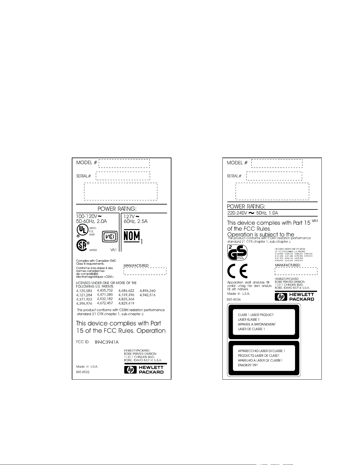
Figure 1-1 HP LaserJet 5L model and serial numbers . . . . . . . . . . . . . . . . . . . . . . 15
Figure 1-2 HP LaserJet 6L model and serial numbers . . . . . . . . . . . . . . . . . . . . . . 16
Figure 1-3 HP LaserJet 6L Pro model and serial numbers . . . . . . . . . . . . . . . . . . . 17
Figure 1-4 Front/side views of the printer . . . . . . . . . . . . . . . . . . . . . . . . . . . . . . . . 19
Figure 1-5 Front door assemblies . . . . . . . . . . . . . . . . . . . . . . . . . . . . . . . . . . . . . . 20
Figure 1-6 Back view of the printer . . . . . . . . . . . . . . . . . . . . . . . . . . . . . . . . . . . . . 21
Figure 2-1 Printer space requirements . . . . . . . . . . . . . . . . . . . . . . . . . . . . . . . . . . 33
Figure 2-2 Toner cartridge distribution . . . . . . . . . . . . . . . . . . . . . . . . . . . . . . . . . . 35
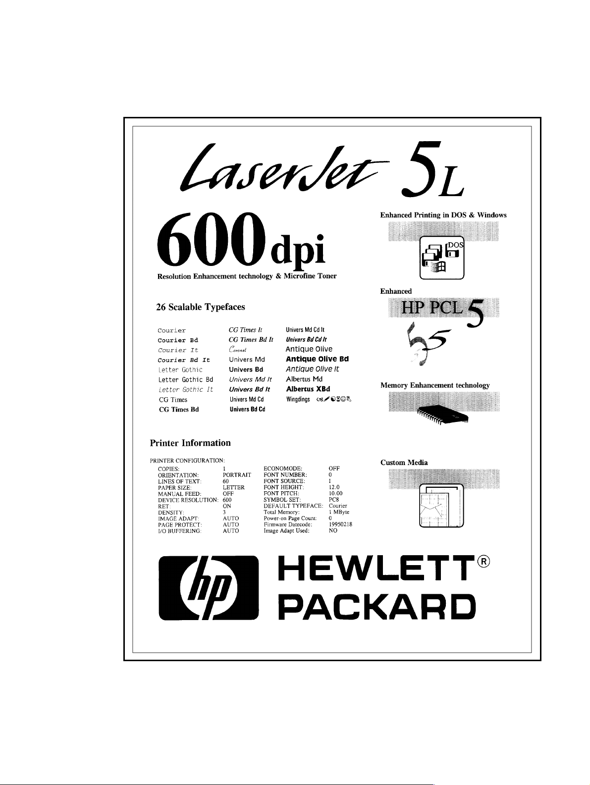
Figure 3-1 Self-test page for HP LaserJet 5L . . . . . . . . . . . . . . . . . . . . . . . . . . . . . 41
Figure 3-2 Self-test page for HP LaserJet 6L . . . . . . . . . . . . . . . . . . . . . . . . . . . . . 42
Figure 3-3 Self-test page for HP LaserJet 6L Pro . . . . . . . . . . . . . . . . . . . . . . . . . . 43
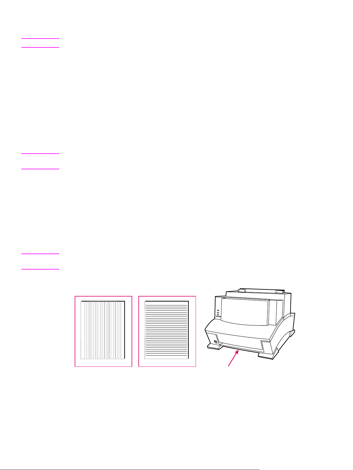
Figure 3-4 Engine test button . . . . . . . . . . . . . . . . . . . . . . . . . . . . . . . . . . . . . . . . . 44
Figure 4-1 Five percent text coverage . . . . . . . . . . . . . . . . . . . . . . . . . . . . . . . . . . 49
Figure 4-2 Static Eliminator Teeth (located in front of the transfer roller) . . . . . . . . 52
Figure 5-1 Printer functional block diagram . . . . . . . . . . . . . . . . . . . . . . . . . . . . . . 54
Figure 5-2 DC Controller loads . . . . . . . . . . . . . . . . . . . . . . . . . . . . . . . . . . . . . . . . 55
Figure 5-3 EconoMode vs. Normal Mode . . . . . . . . . . . . . . . . . . . . . . . . . . . . . . . . 59
Figure 5-4 Image formation block diagram . . . . . . . . . . . . . . . . . . . . . . . . . . . . . . . 61
Figure 5-5 Simplified paper path . . . . . . . . . . . . . . . . . . . . . . . . . . . . . . . . . . . . . . . 63
Figure 5-6 Solenoid and sensors . . . . . . . . . . . . . . . . . . . . . . . . . . . . . . . . . . . . . . 64
Figure 5-7 General timing diagram - HP LaserJet 5L . . . . . . . . . . . . . . . . . . . . . . . 67
Figure 5-8 General timing diagram - HP LaserJet 6L and HP LaserJet 6L ProSL . 68
Figure 6-1 Phillips and PosiDriv screwdrivers . . . . . . . . . . . . . . . . . . . . . . . . . . . . . 71
Figure 6-2 Back Cover removal (1 of 2) . . . . . . . . . . . . . . . . . . . . . . . . . . . . . . . . . 73
Figure 6-3 Back Cover removal (2 of 2) . . . . . . . . . . . . . . . . . . . . . . . . . . . . . . . . . 74
Figure 6-4 EP Door Assembly removal . . . . . . . . . . . . . . . . . . . . . . . . . . . . . . . . . . 75
Figure 6-5 Memory Door removal . . . . . . . . . . . . . . . . . . . . . . . . . . . . . . . . . . . . . . 76
Figure 6-6 Main Cover and Paper Input Assembly removal . . . . . . . . . . . . . . . . . . 77
Figure 6-7 Control Panel removal . . . . . . . . . . . . . . . . . . . . . . . . . . . . . . . . . . . . . . 78
Figure 6-8 Exit Roller removal. . . . . . . . . . . . . . . . . . . . . . . . . . . . . . . . . . . . . . . . . 79
Figure 6-9 Delivery Assembly removal (1 of 2) . . . . . . . . . . . . . . . . . . . . . . . . . . . . 80
Figure 6-10 Delivery Assembly removal (2 of 2) . . . . . . . . . . . . . . . . . . . . . . . . . . . . 81
Figure 6-11 Fuser Pressure Plate removal . . . . . . . . . . . . . . . . . . . . . . . . . . . . . . . . 82
Figure 6-12 Fuser Pressure Plate replacement . . . . . . . . . . . . . . . . . . . . . . . . . . . . 83
Figure 6-13 Heating Element removal (1 of 3) . . . . . . . . . . . . . . . . . . . . . . . . . . . . . 84
Figure 6-14 Heating Element removal (2 of 3) . . . . . . . . . . . . . . . . . . . . . . . . . . . . . 85
Figure 6-15 Heating Element removal (3 of 3) . . . . . . . . . . . . . . . . . . . . . . . . . . . . . 86
Figure 6-16 Pressure Roller Guide removal . . . . . . . . . . . . . . . . . . . . . . . . . . . . . . . 87
Figure 6-17 Face-Up/Face-Down Lever replacement . . . . . . . . . . . . . . . . . . . . . . . . 88
Figure 6-18 Fuser Exit Roller removal . . . . . . . . . . . . . . . . . . . . . . . . . . . . . . . . . . . 89
Figure 6-19 Paper Exit Sensor Flag replacement . . . . . . . . . . . . . . . . . . . . . . . . . . . 90
Figure 6-20 Laser/Scanner Assembly removal . . . . . . . . . . . . . . . . . . . . . . . . . . . . . 91
Figure 6-21 Solenoid removal (1 of 2). . . . . . . . . . . . . . . . . . . . . . . . . . . . . . . . . . . . 92
Figure 6-22 Solenoid removal (2 of 2). . . . . . . . . . . . . . . . . . . . . . . . . . . . . . . . . . . . 93
Figure 6-23 Pickup Roller Assembly removal (1 of 2) . . . . . . . . . . . . . . . . . . . . . . . . 94
Figure 6-24 Pickup Roller Assembly removal (2 of 2) . . . . . . . . . . . . . . . . . . . . . . . . 95
Figure 6-25 Paper Pickup Roller Assembly replacement (inside/front view) . . . . . . 96
Figure 6-26 Paper Feed Frame removal (1 of 4) . . . . . . . . . . . . . . . . . . . . . . . . . . . 97
Figure 6-27 Paper Feed Frame removal (2 of 4) . . . . . . . . . . . . . . . . . . . . . . . . . . . 98
Figure 6-28 Paper Feed Frame removal (3 of 4) . . . . . . . . . . . . . . . . . . . . . . . . . . . 99
Figure 6-29 Paper Feed Frame removal (4 of 4) . . . . . . . . . . . . . . . . . . . . . . . . . . 100
Figure 6-30 Transfer Roller Guide and Transfer Roller removal (inside/back view) 101
Contents 9
Page 12

Figure 6-31 Kick Plate removal . . . . . . . . . . . . . . . . . . . . . . . . . . . . . . . . . . . . . . . .102
Figure 6-32 Kick Plate Spring replacement . . . . . . . . . . . . . . . . . . . . . . . . . . . . . . .103
Figure 6-33 Separation Pad removal . . . . . . . . . . . . . . . . . . . . . . . . . . . . . . . . . . . .104
Figure 6-34 Subpad removal . . . . . . . . . . . . . . . . . . . . . . . . . . . . . . . . . . . . . . . . . .105
Figure 6-35 Feed Assembly removal (1 of 3) . . . . . . . . . . . . . . . . . . . . . . . . . . . . . .106
Figure 6-36 Feed Assembly removal (2 of 3) . . . . . . . . . . . . . . . . . . . . . . . . . . . . . .107
Figure 6-37 Feed Assembly removal (3 of 3) . . . . . . . . . . . . . . . . . . . . . . . . . . . . . .108
Figure 6-38 Memory Door Guide removal . . . . . . . . . . . . . . . . . . . . . . . . . . . . . . . .109
Figure 6-39 Motor removal . . . . . . . . . . . . . . . . . . . . . . . . . . . . . . . . . . . . . . . . . . . .110
Figure 6-40 DC Controller removal (1 of 3) . . . . . . . . . . . . . . . . . . . . . . . . . . . . . . .111
Figure 6-41 DC Controller removal (2 of 3) . . . . . . . . . . . . . . . . . . . . . . . . . . . . . . .112
Figure 6-42 DC Controller removal (3 of 3) . . . . . . . . . . . . . . . . . . . . . . . . . . . . . . .113
Figure 6-43 Formatter Board removal . . . . . . . . . . . . . . . . . . . . . . . . . . . . . . . . . . .114
Figure 7-1 Paper path and components . . . . . . . . . . . . . . . . . . . . . . . . . . . . . . . .118
Figure 7-2 DC Controller PCA components . . . . . . . . . . . . . . . . . . . . . . . . . . . . .119
Figure 7-3 Heating element resistance check . . . . . . . . . . . . . . . . . . . . . . . . . . . .124
Figure 7-4 Engine test . . . . . . . . . . . . . . . . . . . . . . . . . . . . . . . . . . . . . . . . . . . . . .133
Figure 7-5 Toner cartridge high-voltage connection points (1 of 2) . . . . . . . . . . . .135
Figure 7-6 Toner cartridge high-voltage connection points (2 of 2) . . . . . . . . . . . .136
Figure 7-7 Overriding PS204 and SW101 . . . . . . . . . . . . . . . . . . . . . . . . . . . . . . .138
Figure 7-8 Repetitive image defect ruler . . . . . . . . . . . . . . . . . . . . . . . . . . . . . . . .139
Figure 7-9 Main wiring diagram . . . . . . . . . . . . . . . . . . . . . . . . . . . . . . . . . . . . . . .140
Figure 8-1 Major assembly locations . . . . . . . . . . . . . . . . . . . . . . . . . . . . . . . . . . .147
Figure 8-2 Covers and doors . . . . . . . . . . . . . . . . . . . . . . . . . . . . . . . . . . . . . . . . .148
Figure 8-3 Internal components (1 of 3) . . . . . . . . . . . . . . . . . . . . . . . . . . . . . . . . .150
Figure 8-4 Internal components (2 of 3) . . . . . . . . . . . . . . . . . . . . . . . . . . . . . . . . .152
Figure 8-5 Internal components (3 of 3) . . . . . . . . . . . . . . . . . . . . . . . . . . . . . . . . .154
Figure 8-6 DC Controller/formatter and cables . . . . . . . . . . . . . . . . . . . . . . . . . . .156
Figure 8-7 Pickup Roller assembly. . . . . . . . . . . . . . . . . . . . . . . . . . . . . . . . . . . . .158
Figure 8-8 Feed assembly . . . . . . . . . . . . . . . . . . . . . . . . . . . . . . . . . . . . . . . . . . .160
Figure 8-9 Separation Guide assembly . . . . . . . . . . . . . . . . . . . . . . . . . . . . . . . . .162
Figure 8-10 Delivery assembly. . . . . . . . . . . . . . . . . . . . . . . . . . . . . . . . . . . . . . . . .164
Figure A-1 VCCI statement (Japan) . . . . . . . . . . . . . . . . . . . . . . . . . . . . . . . . . . . .180
10 EN
Page 13

Tables
Table 1-1 Printer Features . . . . . . . . . . . . . . . . . . . . . . . . . . . . . . . . . . . . . . . . . . . . . . . . . .14
Table 1-2 Printer Features . . . . . . . . . . . . . . . . . . . . . . . . . . . . . . . . . . . . . . . . . . . . . . . . . .14
Table 1-3 Performance specifications . . . . . . . . . . . . . . . . . . . . . . . . . . . . . . . . . . . . . . . . .18
Table 1-4 Electrical specifications . . . . . . . . . . . . . . . . . . . . . . . . . . . . . . . . . . . . . . . . . . .18
Table 1-5 Acoustic emissions . . . . . . . . . . . . . . . . . . . . . . . . . . . . . . . . . . . . . . . . . . . . . . . 18
Table 1-6 Related documentation . . . . . . . . . . . . . . . . . . . . . . . . . . . . . . . . . . . . . . . . . . . . 22
Table 2-1 Environmental requirements . . . . . . . . . . . . . . . . . . . . . . . . . . . . . . . . . . . . . . . . 32
Table 2-2 Printer dimensions . . . . . . . . . . . . . . . . . . . . . . . . . . . . . . . . . . . . . . . . . . . . . . . .33
Table 3-1 Indicator Lights . . . . . . . . . . . . . . . . . . . . . . . . . . . . . . . . . . . . . . . . . . . . . . . . . .38
Table 3-2 Control Panel Button usage. . . . . . . . . . . . . . . . . . . . . . . . . . . . . . . . . . . . . . . . . 40
Table 4-1 Life expectancy of consumables . . . . . . . . . . . . . . . . . . . . . . . . . . . . . . . . . . . . .48
Table 4-2 Cleaning printer components. . . . . . . . . . . . . . . . . . . . . . . . . . . . . . . . . . . . . . . . 51
Table 5-1 Solenoid and sensors . . . . . . . . . . . . . . . . . . . . . . . . . . . . . . . . . . . . . . . . . . . . .64
Table 5-2 Printer timing . . . . . . . . . . . . . . . . . . . . . . . . . . . . . . . . . . . . . . . . . . . . . . . . . . . .66
Table 7-1 Printer status messages . . . . . . . . . . . . . . . . . . . . . . . . . . . . . . . . . . . . . . . . . . 121
Table 7-2 Unclearable error . . . . . . . . . . . . . . . . . . . . . . . . . . . . . . . . . . . . . . . . . . . . . . . .122
Table 7-3 Service and error messages . . . . . . . . . . . . . . . . . . . . . . . . . . . . . . . . . . . . . . . 123
Table 7-3 Service and error messages (Continued 2 of 3) . . . . . . . . . . . . . . . . . . . . . . . .124
Table 7-3 Service and error messages (Continued 3of 3) . . . . . . . . . . . . . . . . . . . . . . . . .125
Table 7-4 High-voltage power supply check . . . . . . . . . . . . . . . . . . . . . . . . . . . . . . . . . . .135
Table 7-5 Paper curl troubleshooting . . . . . . . . . . . . . . . . . . . . . . . . . . . . . . . . . . . . . . . . . 137
Table 7-6 Cable pinouts . . . . . . . . . . . . . . . . . . . . . . . . . . . . . . . . . . . . . . . . . . . . . . . . .141
Table 8-1 Accessories and supplies . . . . . . . . . . . . . . . . . . . . . . . . . . . . . . . . . . . . . . . . . 145
Table 8-2 Common fasteners used in the printer. . . . . . . . . . . . . . . . . . . . . . . . . . . . . . . .146
Table 8-3 Covers and doors . . . . . . . . . . . . . . . . . . . . . . . . . . . . . . . . . . . . . . . . . . . . . . . 149
Table 8-4 Internal components . . . . . . . . . . . . . . . . . . . . . . . . . . . . . . . . . . . . . . . . . . . . .151
Table 8-5 Internal components (2 of 3) . . . . . . . . . . . . . . . . . . . . . . . . . . . . . . . . . . . . . . . 153
Table 8-6 Internal components (3 of 3) . . . . . . . . . . . . . . . . . . . . . . . . . . . . . . . . . . . . . . . 155
Table 8-7 DC Controller case . . . . . . . . . . . . . . . . . . . . . . . . . . . . . . . . . . . . . . . . . . . . . .157
Table 8-8 Pickup Roller assembly . . . . . . . . . . . . . . . . . . . . . . . . . . . . . . . . . . . . . . . . . . .159
Table 8-9 Feed assembly . . . . . . . . . . . . . . . . . . . . . . . . . . . . . . . . . . . . . . . . . . . . . . . . . 161
Table 8-10 Separation Guide assembly. . . . . . . . . . . . . . . . . . . . . . . . . . . . . . . . . . . . . . . .163
Table 8-11 Delivery assembly . . . . . . . . . . . . . . . . . . . . . . . . . . . . . . . . . . . . . . . . . . . . . . . 165
Table A-1 Alphabetical parts list . . . . . . . . . . . . . . . . . . . . . . . . . . . . . . . . . . . . . . . . . . . .167
Table A-2 Numerical parts list . . . . . . . . . . . . . . . . . . . . . . . . . . . . . . . . . . . . . . . . . . . . . 172
Contents 11
Page 14

12 EN
Page 15

1 Product infor mation
Chapter contents
Printer features . . . . . . . . . . . . . . . . . . . . . . . . . . . . . . . . . . . . . . . . . . . . . . . . . . . . . . . . . . . . . . .14
Paper capacities and sizes . . . . . . . . . . . . . . . . . . . . . . . . . . . . . . . . . . . . . . . . . . . . . . . . . . . . . .14
Identification . . . . . . . . . . . . . . . . . . . . . . . . . . . . . . . . . . . . . . . . . . . . . . . . . . . . . . . . . . . . . . . . .15
HP LaserJet 6L Gold. . . . . . . . . . . . . . . . . . . . . . . . . . . . . . . . . . . . . . . . . . . . . . . . . . . . . . . .15
Model and serial . . . . . . . . . . . . . . . . . . . . . . . . . . . . . . . . . . . . . . . . . . . . . . . . . . . . . . . . . . . 15
Specifications . . . . . . . . . . . . . . . . . . . . . . . . . . . . . . . . . . . . . . . . . . . . . . . . . . . . . . . . . . . . . . . . 18
Product overview. . . . . . . . . . . . . . . . . . . . . . . . . . . . . . . . . . . . . . . . . . . . . . . . . . . . . . . . . . . . . .19
Front/side views of the printer. . . . . . . . . . . . . . . . . . . . . . . . . . . . . . . . . . . . . . . . . . . . . . . . .19
Front door assemblies. . . . . . . . . . . . . . . . . . . . . . . . . . . . . . . . . . . . . . . . . . . . . . . . . . . . . . .20
Back view of the printer. . . . . . . . . . . . . . . . . . . . . . . . . . . . . . . . . . . . . . . . . . . . . . . . . . . . . .21
Service approach . . . . . . . . . . . . . . . . . . . . . . . . . . . . . . . . . . . . . . . . . . . . . . . . . . . . . . . . . . . . .22
Parts Exchange Program . . . . . . . . . . . . . . . . . . . . . . . . . . . . . . . . . . . . . . . . . . . . . . . . . . . . 22
Ordering parts. . . . . . . . . . . . . . . . . . . . . . . . . . . . . . . . . . . . . . . . . . . . . . . . . . . . . . . . . . . . .22
Ordering related documentation . . . . . . . . . . . . . . . . . . . . . . . . . . . . . . . . . . . . . . . . . . . . . . .22
Technical assistance . . . . . . . . . . . . . . . . . . . . . . . . . . . . . . . . . . . . . . . . . . . . . . . . . . . . . . . . . . . 23
HP Customer Care . . . . . . . . . . . . . . . . . . . . . . . . . . . . . . . . . . . . . . . . . . . . . . . . . . . . . . . . .23
HP worldwide sales and service offices . . . . . . . . . . . . . . . . . . . . . . . . . . . . . . . . . . . . . . . . . 25
Warranty . . . . . . . . . . . . . . . . . . . . . . . . . . . . . . . . . . . . . . . . . . . . . . . . . . . . . . . . . . . . . . . . . . . .28
Hardware service during the warranty period. . . . . . . . . . . . . . . . . . . . . . . . . . . . . . . . . . . . .28
Hardware service after the warranty period . . . . . . . . . . . . . . . . . . . . . . . . . . . . . . . . . . . . . .28
HP LaserJet Toner Cartridge warranty . . . . . . . . . . . . . . . . . . . . . . . . . . . . . . . . . . . . . . . . . .29
Voltage conversions . . . . . . . . . . . . . . . . . . . . . . . . . . . . . . . . . . . . . . . . . . . . . . . . . . . . . . . .29
EN Chapter contents 13
Page 16
Printer features
Note All references in this manual to the HP LaserJet 6L printer also apply to the HP LaserJet 6L Gold
printer.
Table 1-1 Printer Features
Feature Description
Print Speed 4 ppm (HP LaserJet 5L); 6 ppm (HP LaserJet 6L/6L Gold and HP LaserJet
6L Pro)
Text and Graphics Resolution 300 or 600 dpi
Printer Language Enhanced PCL 5 (or host-based on HP LaserJet 6L/6L Gold)
Monthly Usage (pages) 4,000 pages (HP LaserJet 5L); 6,000 pages (HP LaserJet 6L/6L Gold)
Memory:
Standard
1
5L and 6L/6L Gold = 1 MB RAM, 2 MB ROM
6L Pro = 4 MB RAM, 4 MB ROM
Maximum
Capacity
Internal Typefaces 26 Scalable Typefaces
Standard Interfaces IEEE-1284 parallel
Power Control SleepMode
Control Pane l 3 LEDs and 1 Control Panel Button
EconoMode (toner saving) Yes
1. Print er memor y is optimized with Memory Enhan cement technology (MEt).
2. Not available for the HP LaserJet 6L Pro, 4 MB standard.
3. JEDI A (Japanese Electronic Device Industry Association) is a group of DRAM suppliers who have standardized
DRAM and other CMOS products.
5L and 6L/6L Gold = 9 MB total (available in increments of 1, 2, 4, and 8
2
MB)
5 V JEDIA card
3
Paper capacities and sizes
Table 1-2 Printer Features
Feature Description
Paper Input Tray Capacity Holds up to 100 sheets of regular weight paper or up to 10 envelopes
Paper Output Bin Capacity Holds up to 100 sheets
Single Sheet Input Slot 1
Minimum Paper Size 76 mm by 127 mm (3 by 5 inches)
Maximum Paper Size 216 mm by 356 mm (8.5 by 14 inches)
14 Product information EN
Page 17
Identification
HP LaserJet 6L Gold
The HP LaserJet 6L Gold shares the same characteristics as the HP LaserJet 6L. For the purposes
this manual, “HP LaserJet 6L” refers to both the 6L and the 6L Gold.
Model and serial
The model number and serial numbers are listed on Identification Labels located on the bottom of the
printer. The model number is alphanumeric, such as C3941A for the HP LaserJet 5L printer, C3990A
for the HP LaserJet 6L printer, and C8060A for the HP LaserJet 6L Pro printer.
The serial number contains information about the Country of Origin, the Revision Level, the
Production Code, and production number of the printer.
The labels also contain power rating and regulatory information.
Figure 1-1 HP LaserJet 5L model and serial numbers
EN Identification 15
Page 18
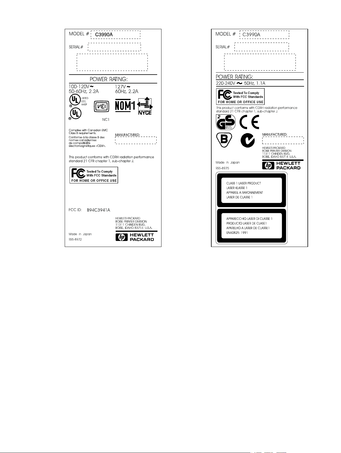
Figure 1-2 HP LaserJet 6L model and serial numbers
16 Product information EN
Page 19
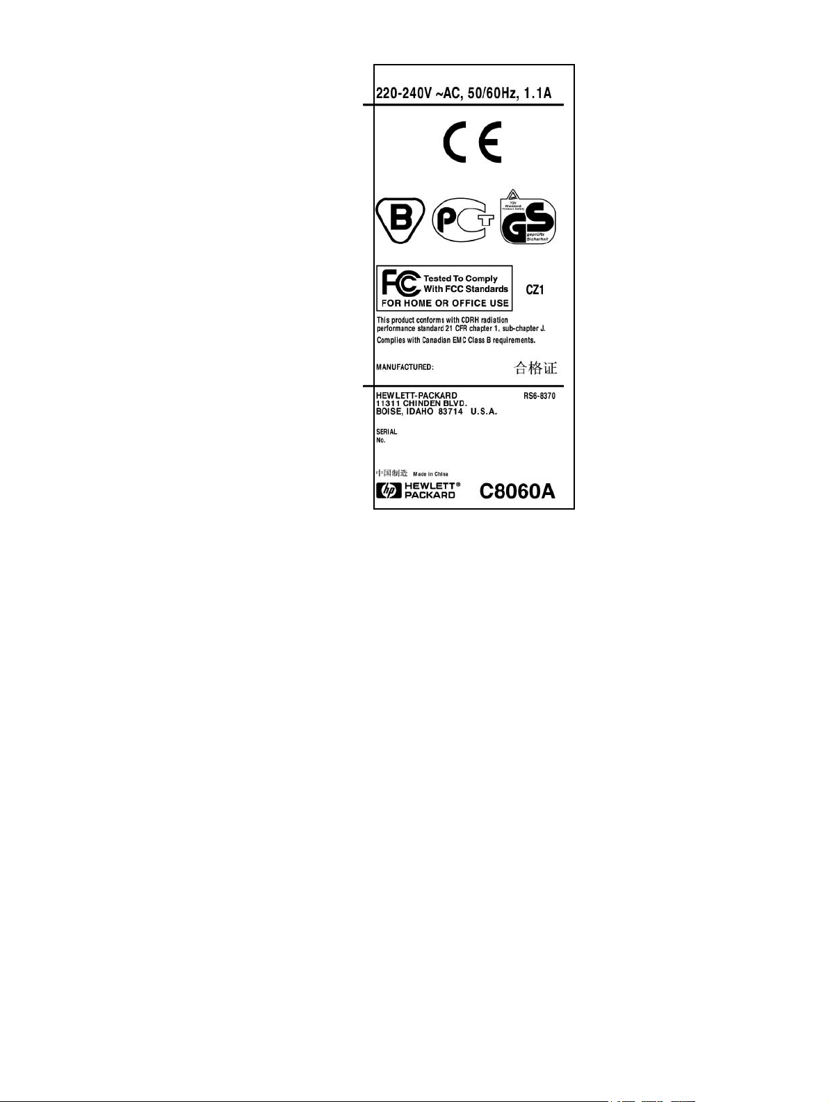
Figure 1-3 HP LaserJet 6L Pro model and serial numbers
EN Identification 17
Page 20
Specifications
Table 1-3 Performance specifications
Category Specification
Print Speed1: HP LaserJet 5L
Print Speed: HP LaserJet 6L
Print Speed: HP LaserJet 6L Pro
Monthly Usage (Duty Cycle): HP LaserJet 5L
Monthly Usage (Duty Cycle): HP LaserJet 6L
Monthly Usage (Duty Cycle): HP LaserJet 6L Pro
Life Expectancy of Toner Cartridge (pages)
First Print
HP LaserJet 5L
HP LaserJet 6L
HP LaserJet 6L Pro
1. Actual speed depends on data complexity and software handling efficiency.
2. T oner Cartridge life can be extended by using EconoMode.
2
4 ppm
6 ppm
6 ppm
4,000 pages
6,000 pages
6,000 pages
2,500 pages at 5% coverage
A4: <23 seconds
Letter: <23 seconds
A4: <23 seconds
Letter: <23 seconds
A4: 18 seconds
Letter: 18 seconds
Table 1-4 Electrical specifications
Volts Frequency Amps Watts (typical)
120 Vac ± 10%
100 Vac ± 10%
220 Vac ± 10%
240 Vac ± 10%
1. Minimum recommended circuit capacity for product.
2. HP LaserJet 6L Pro operates at 220/240 Volts only.
50/60 Hz ± 2 Hz
50/60 Hz ± 2 Hz
2
50 Hz ± 2 Hz
50 Hz ± 2 Hz
3.5 @ 120v
1.8 @ 230v Printing = 100 (5L) 150 (6L) 150 (6L Pro)
1
Printing = 100 (5L) 150 (6L) 150 (6L Pro)
SleepMode = 6 (5L) 4 (6L) 4 (6L Pro)
SleepMode = 6 (5L) 4 (6L) 4 (6L Pro)
Table 1-5 Acoustic emissions
During Printing 5.6 Bels Sound Power Level (per ISO 9296)
During Standby & SleepMode Silent
18 Product information EN
Page 21
Product overview
1
4
5
6
7
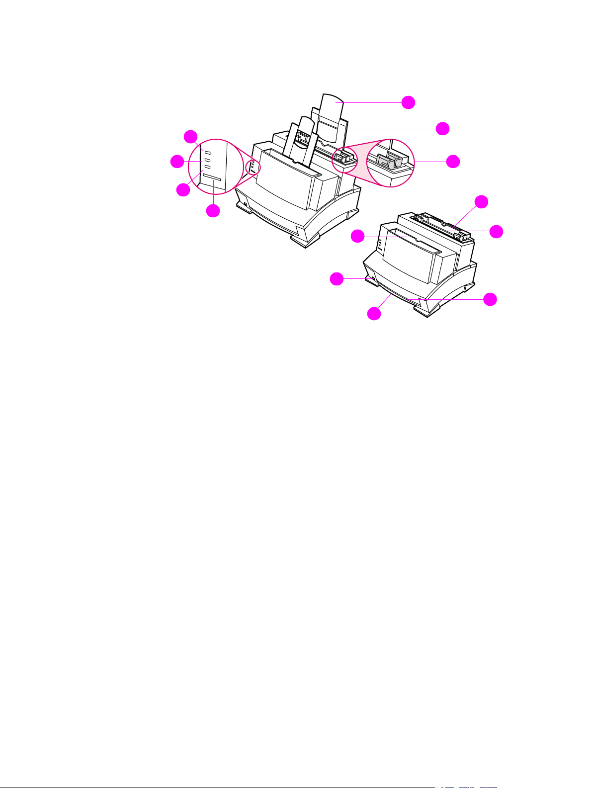
Figure 1-4 Front/side views of the printer
1 Paper Input Support (not present on the HP LaserJet 6L Pro)
2 Paper Output Support (not present on the HP LaserJet 6L Pro)
3 Paper Guides
2
3
11
8
9
10
12
13
4 Error (top) Indicator Light
5 Data (middle) Indicator Light
6 Ready (bottom) Indicator Light
7 Control Panel Button
8 Pa per Output Bin
9 Paper Path Lever
10 Serial and Model Number (under printer)
11 Paper Input Tray
12 Single Sheet Input Slot
13 Front Output Slot (face-up)
EN Product overview 19
Page 22
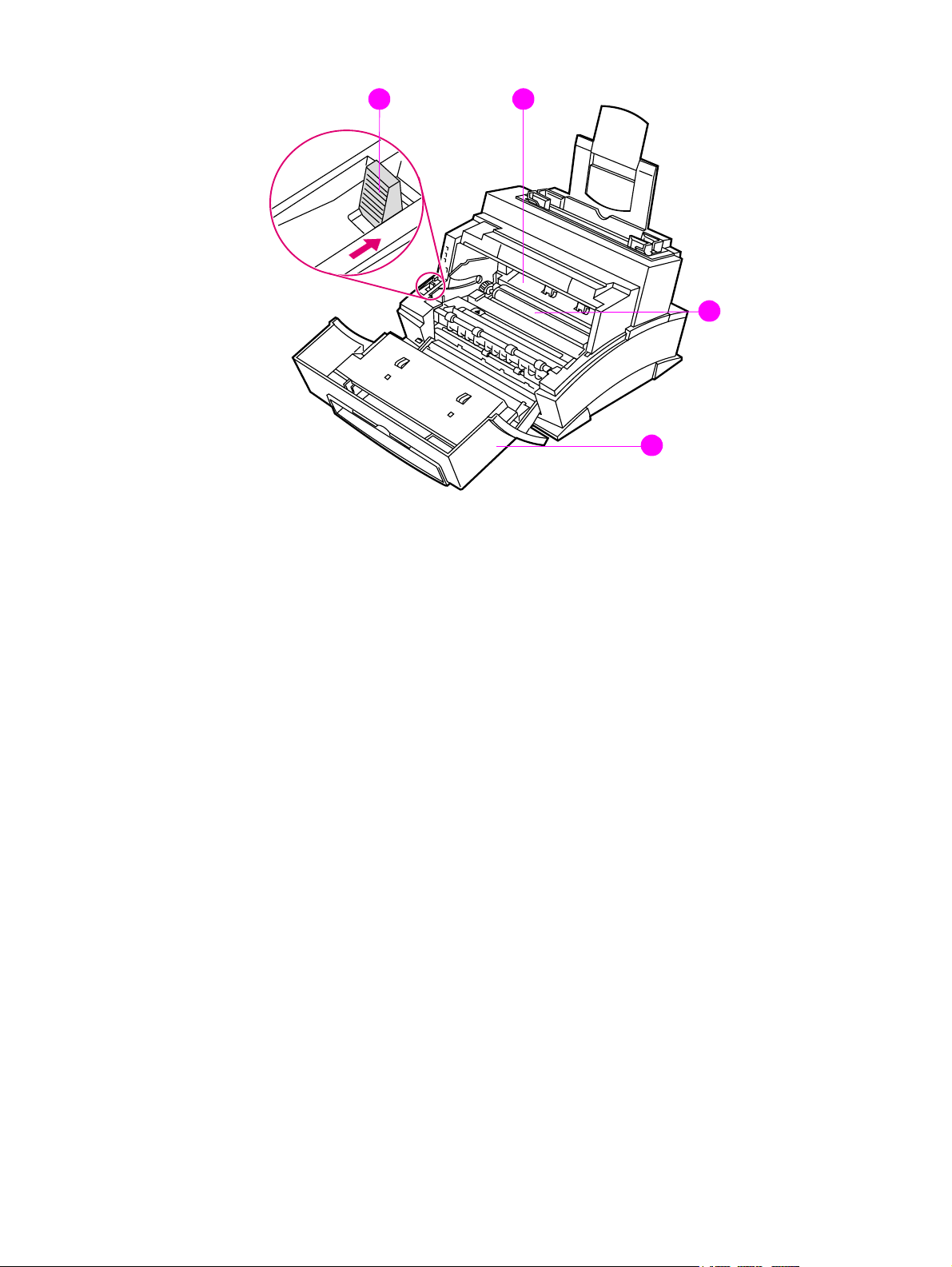
Figure 1-5 Front door assemblies
14
15
16
17
14 Paper Release Lever
15 Toner Cartridge Compar tm ent
16 Transfer Roller (do not touch)
17 EP Door
20 Product information EN
Page 23
18
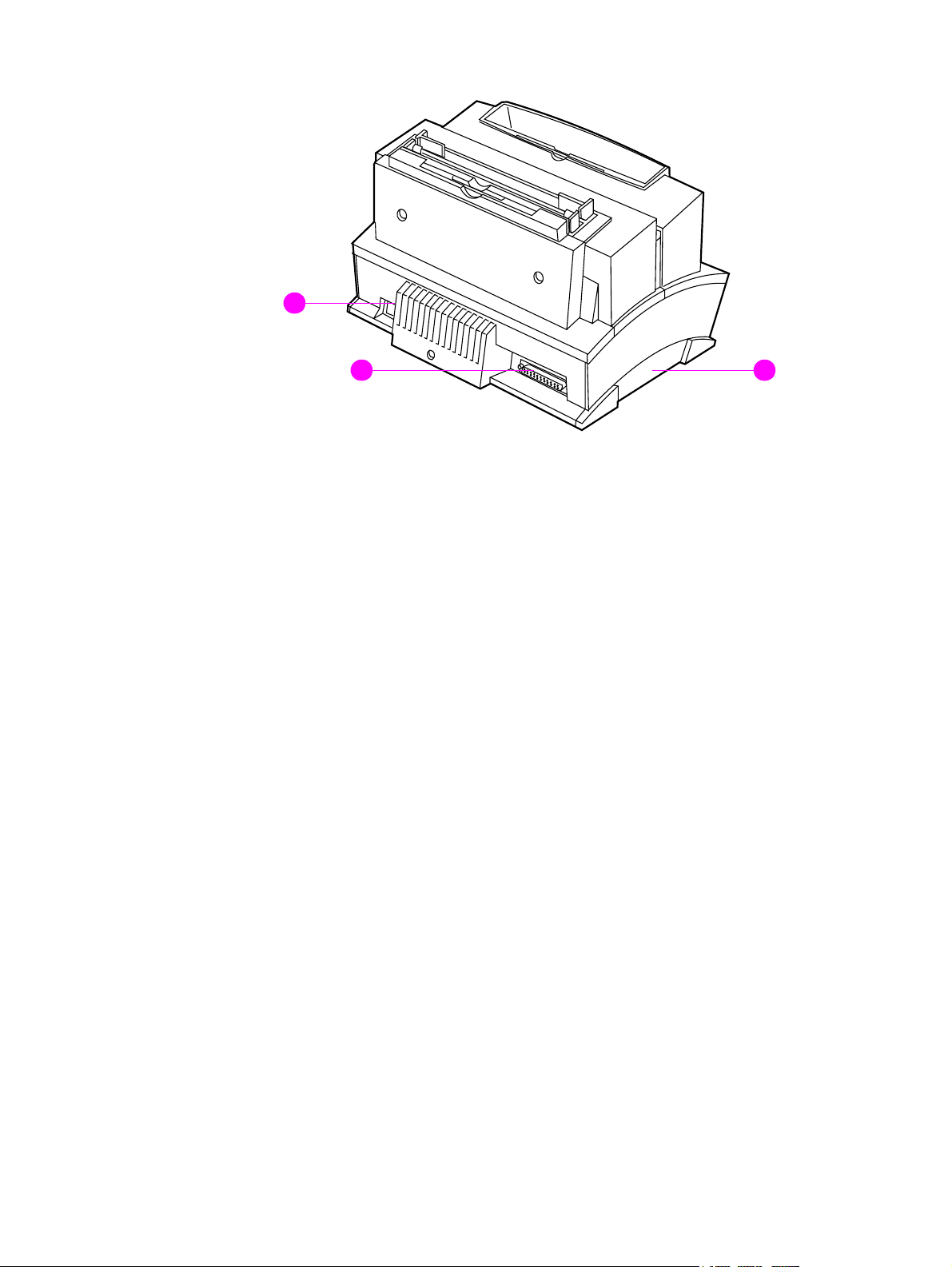
Figure 1-6 Back view of the printer
18 Power Cable Connector
19 Parallel Cable Connector
20 Memory Expansion Cover (not present on the HP LaserJet 6L Pro)
2019
EN Product overview 21
Page 24

Service approach
Repair of the printer normally begins with the use of the printer’s internal diagnostics in conjunction
with the troubleshooting procedures in Chapter 7. Once a faulty part is located, repair is generally
accomplished by assembly level replacement of Field Replaceable Units (FRUs). Some mechanical
assemblies may be repaired at the subassembly level. PCA component replacement is not
supported by Hewlett-Packard. Part numbers for all FRUs are located in Chapter 8 of this manual.
Parts Exchange Program
HP offers remanufactured assemblies for some selected parts. These are identified in Chapter 8 and
can be ordered through HP’s
Commercial Service and Support Organization-Europe (CSSO-E)
Ordering parts
Field replaceable part numbers are listed in Chapter 8 of this manual. Replacement parts may be
ordered from HP's Commercial Service and Support Organization-Americas (CSSO-A), or
Commercial Service and Support Organization-Europe (CSSO-E).
Ordering related documentation
Table 1-6 on the following page lists part numbers and where to order related documentation.
Commercial Service and Support Organization-Americas (CSSO-A), or
.
Contacting HP to place an order
To order parts or related documentation, contact one of the following HP support organizations:
l CSSO-A (Commercial Service and Support Organization-Americas)
(800) 227-8164 (U.S. Only)
l CSSO-E (Commercial Service and Support Organization-Europe)
(49 7031) 142253
Table 1-6 Related documentation
Description Part Number CSSO-A CSSO-E
HP LaserJet Family Quick Reference Service Guide 5021-0369 X X
HP LaserJet 5L Printer User’s Ma n ual C3941-90901 X
HP LaserJet 6L Printer User’s Ma n ual C3990-90901 X
HP LaserJet 6L Pro Printer User’s Guide C8060-90901
HP PCL5 Printer Language Technical Reference Information
Package
HP LaserJet Printer Family Paper Specifications Guide 5963-7863 X X
LaserJet Basic Hardware Training Course 5961-0880 X X
HP LaserJet 5L/6L/6L Gold/6L Pro Service and Support
Documentation and Training CD-ROM
5010-3994 X X
C8060-60102
(English)
X
X
C8060-60103
(Simplified Chinese)
X
22 Product information EN
Page 25

Technical assistance
HP Customer Care
Along with your product, you receive a variety of support services from Hewlett-Packard and our
support partners designed to give you the results you need, quickly and professionally.
Online Services: for 24hour access to information
over your Internet
connection, we suggest
these services.
Obtaining Software Visit: http://www.hp.com/go/support/ (site is in English)
Australia: +61 3 8877 8000
China: +86 10 6564 5959
Argentina: (541) 778 8380
Mexico: 800-427-6684
Spain: +44 (0) 1429 520 012
Portugal: +44 (0) 1429 890 466
German: +44 (0) 1429 863 353
French (Europe): +44 (0) 1429 863 343
Italian: +44 (0) 1429 890 466
English: +44 (0) 1429 865 511
Canada and US: (661) 257 5565
Taiwan: +888 (2) 2717 0055
Korea: +82 (2) 3270 0805
Greece, Ireland, and the UK: +44 (0) 1429 865 511
Hong Kong SAR, Malaysia,
and Singapore: +65 740 4477
India: (91) (11) 682 6035
New Zealand: +64 9 356 6640
HP Direct Ordering for
Accessories and Supplies
(U.S. and Canada):
HP Support Assistant
compact disc
(U.S., Canada, Singapore,
Hong Kong SAR, Malaysia):
HP Service Information
(U.S. and Canada):
World Wide Web URL: For information specific to the HPLaserJet 5L/
6L6L Gold/6L Pro products:
http://www.hp.com/go/support/ (site is in English)
Call:
Call (1) (800) 538-8787 (U.S.) or (1) (800) 387-3154 (Canada).
This support tool offers a comprehensive online information system
designed to provide technical and product information on HP products. T o
subscribe to this quarterly service in the U.S. or Canada, call (1) (800)
457-1762. In Hong Kong SAR, Malaysia, or Singapore, call Fulfill Plus at (65)
740-4477.
To locate HP-authorized dealers, call (1) (800) 243-9816 in the U.S. or
(1) (800) 387-3154 in Canada.
EN T echnical assistance 23
Page 26

Customer Care options worldwide
HP Customer Care and Product Repair Assistance for the U.S. and Canada:
Call (208) 323-2551 in the United States or (905) 206-4663 in Canada Monday through Friday 6 am to 10
pm and Saturday 9 am to 4 pm (Mountain Time) free of charge during the warranty period. However, your
standard long-distance phone charges still apply. Have y our system nearby and your serial number ready
when calling.
If you know your printer needs repair, call 1-800-243-9816 to locate your nearest HP-authorized service
provider, or call 208-323-2551 for HP centralized service dispatch.
Post-warranty telephone assistance is available to answer your product questions. Call (1) (900) 555-1500
($2.50* per minute, U.S. only) or call 1-800-999-1148 ($25* per call, Visa or MasterCard, U.S. and
Canada) Monday through Friday from 7 am to 6 pm and Saturday from 9 am to 3 pm (Mountain Time).
Charges begin only when you connect with a support technician. *Prices subject to change.
European HP Customer Care and In-Country/Region Support
Open Monday through Friday 8:30-18:00 CET
HP provides a free telephone support service during the warranty period. By calling a telephone number
listed below, you will be connected to a responsive team waiting to help you. If you require support after
your warranty has expired, you can receive support for a fee through the same telephone number. The fee
is charged on a per-incident basis. When calling HP, have the following information ready: product name
and serial number, date of purchase, and description of the problem.
Israel: +972 (0)9 9524848
Denmark: +45 39 29 4099
Sweden: +46 (0)8 619 2170
Spain: +34 902 321 123
Portugal: +351 21 3176333
Norway: +47 22 11 62 99
Italy: +39 02 264 10350
Austria: +43 (0) 7114 201080
Germany: +49 (180) 52 58 143
Belgium: +32 (0)2 626 8807
France: +33 (0)1 43 62 3434
Finland: +358 (0)203 47 288
Belgium: +32 (0)2 626 8806 (Dutch)
+32 (0)2 626 8807 (French)
Ireland: +353 (0)1 662 5525
U.K.: +44 (0)171 512 5202
Greece: +30 (0) 16196411
Switzerland: +41 (0)848 80 11 11
English in Europe +44 (0) 171 512 52 02
Switzerland: +41 (0)848 80 11 11
the Netherlands: +31 (0) 20 606 8751
English in other
European countries: +44 (0)171 512 52 02
Open Monday through Friday 8:00-19:00
If you require telephone support, call the number below. If you require additional product repair services,
see “HP worldwide sales and service offices.”
Australia: (61) (3) 8877-8000
Hong Kong SAR: 800 96 7729
Malaysia: +60 3 295 2566
Taiwan: +886 (2) 2717 0055
Korea: (82) (2) 3270-0700
Argentina: (541) 778 8380 Mexico (Mexico City): 800-427-6684
Poland: +48 22 519 06 00
Russia and the Ukraine: +7 095 797 3520 (Moscow)
+7 812 346 7997 (St. Petersburg)
+7 (380-44) 490-3520 (Ukraine)
China: +86 (0)10 6564 5959
Hong Kong SAR: 800 96 7729
Hungary: +365 (0)1 3821111
In-country/region support
New Zealand: +64 9 356 6640
Singapore: +65 272 5300
24 Product information EN
Page 27

HP worldwide sales and service offices
Argentina Australia Austria
Hewlett-Packard Argentina
Montañeses 2140
1428 Buenos Aires
Phone: (54) (1) 787-7115
Fax: (54) (1) 787-7287
Hewlett-Packard Head office
Hewlett-Packard Australia Ltd.
31-41 Joseph Street
Blackburn, VIC 3130
Phone: (61) (3) 9272-2895
Fax: (61) (3) 898-7831
Service and Support
Hewlett-Packard
351 Burwood Hwy
Forest Hill
VIC 3131
Phone: (61) (3) 8877-5786
Hewlett-Pack a rd GmbH
Lieblgasse 1
A-1222 Vienna
Phone: (43) (1) 25000-555
Fax: (43) (1) 25000-500
Belgium China Denmark
Hewlett-Packard Belgium S.A. NV
Boulevard de la Woluwe-Woluwedal
100-102
B-1200 Brussels
Phone: (32) (2) 778-31-11
Fax: (32) (2) 763-06-13
China Hewlett-Packard Co. Ltd.
9/F, HP Building
No. 2 Dong San Huan Nan Lu
Chao Yang District
Beijing 100022, P.R. China
Phone: (86 10) 6564 3888
Customer Information Center:
Phone: (86 10) 6564-3888 or
(86 10) 6564-5959
Hewlett-Pack ard A/S
Kongev ejen 25
DK-3460 Birkerød
Denmark
Phone: (45) 3929 4099
Fax: (45) 4281-5810
Finland France Germany
Hewlett-Packard Oy
Piispankalliontie 17
FIN-02200 Espoo
Phone: (358) (9) 887-21
Fax: (358) (9) 887-2477
Hewlett-Packard France
42 Quai du Point du Jour
F-92659 Boulogne Cedex
Phone: (33) (146) 10-1700
Fax: (33) (146) 10-1705
Hewlett-Pack a rd GmbH
Herrenberger Strasse 130
71034 Böblingen
Phone: (49) (0) 180 532-6222
(49) (0) 180 525-8143
Fax: (49) (0) 180 531-6122
Greece Hong Kong SAR Hungary
Hewlett-Packard Hellas
62 Kiffisias Av.
Polis Center
Maroussi
151 25 Athens
Greece
Phone: (30) (1) 619-6411
Fax: (30) (1) 619-6512
Hewlett-Packard Asia Pacific Ltd
25/F City Plaza One
1111 King’s Road, Taikoo Shing,
Hong Kong SAR
Phone; (8 52) 2599-7777
Fax: (8 52) 2506-9776
Hardware Repair Center:
Phone: (8 52) 2599-7000
Extended Warranty Support:
Phone: (8 52) 2599-7000
Customer Information Center:
Phone: 8 52) 2599-7066
Hewlett-Packard Magyarország Kft.
Neumann János u. 1
H-1111 Budapest
Phone: (36) (1) 382-6666
Fax: (36) (1) 382-6777
Hardware Repair Center:
Phone: (36) (1) 343-0312
Customer Information Center:
Phone: (36) (1) 343-0310
EN T echnical assistance 25
Page 28

India Indonesia Israel
Hewlett-Packard India Ltd.
Chandiwala Estate
Maa Anandmai Marg
Kalkaji, New Delhi - 110019
Phone: (91 11) 682-6000,
(91 11) 682-6035
Fax: (91 11) 682-6030
Hardware Repair Center and
Extended Warranty Support:
Phone: (91 11) 682-6042
Customer Information Center:
Phone: (91 11) 682-6000 or
(91 11) 682-6035
Hewlett-Packard Berca Servisindo
Sentral Senayan 1, 8th floor
Jl. Asia Afrika no. 8
Jakarta 10270
Indonesia
Phone: (62 21) 350-3408
Hardware Repair Center and
Extended Warranty Support:
Phone: (62 21) 3483-4567
Fax: (62 21) 352-2048
Customer Information Center:
Phone: (62 21) 550-5408
Hewlett-Packard Israel Ltd.
11, Hashlosha St.
Tel Aviv 67060
Phone: (972) (3) 5 38 03 00
Fax: (972) (3) 5 38 03 51
Customer Care Center
Phone: (972) (9) 9 52 48 48
Italy Korea México
Hewlett-Packard Italiana SpA
Via Giuseppe di Vittorio, 9
Cernusco Sul Naviglio
I-20063 (Milano)
Phone: (39) (2) 921-21
Fax: (39) (2) 921-04473
Hewlett-Packard Korea, Ltd.
HP Korea House,
23-6 Yoido-dong,
Youngdeungpo-gu, Seoul 150-724,
Korea
Yoido P.O. Box 595
Phone: (82) (2)2199-0114
Hewlett-Pack ard de México, S.A. de
C.V.
Prolongación Reforma No. 700
Lomas de Santa Fe
01210 México, D.F.
Phone: 01-800-22147
Outside Mexico City
Phone: 01 800-90529
Middle-East Region Netherlands New Zealand
Hewlett-Packard Middle-East
P.O.-Box 17295
Jebel Ali Free Zone
Dubia, UAE
Phone: (97) 14 88 15 456
Fax: (97) 14 88 14 529
Hewlett-Packard Nederland BV
Startbaan 16
1187 XR Amstelveen
Postbox 667
NL-1180 AR Amstelveen
Phone: (31) (0) 20 547-6666
Fax: (31) (0) 20 547-7755
Hewlett-Packard (NZ) Limited
Ports of Auckland Building
Princes Wharf, Quay Street
P.O. Box 3860
Auckland
Phone: (64) (9) 356-6640
Fax: (64) (9) 356-6620
Hardware Repair Center and Extended
Warranty Support:
Phone: (64) (9) 0800-733547
Customer Information Center:
Phone: (64) (9) 0800-651651
Norway Poland Portugal
Hewlett-Packard Norge A/S
Postboks 60 Skøyen
Drammensveien 169
N-0212 Oslo
Phone: (47) 2273-5600
Fax: (47) 2273-5610
Hewlett-Packard Polska
Al. Jerozolimskic 181
02-222 Warszawa
Phone: (48-22) 608-7700
Fax: (48-22) 608-76-00
Hewlett-Packard Portugal
Quinta da Fonte
Edifico Bartolomeu Dias
Porto Salvo
2780-667 Oeiras
Portugal
Phone: (351) (21) 4 82 85 00
Fax: (351) (21) 4 41 70 02
26 Product information EN
Page 29

Russian Federation Singapore Spain
Hewlett-Packard Company
Representative Office
Kosmodamianskaya naberezhnaya 52,
Building 1
113054 Moscow
Phone: (7) (0) 95 797-3500
Fax: (7) (0) 95 797-3501
Hewlett-Packard Singapore
(Service) Pte Ltd
438A Alexandra Road
Blk A Alexandra Technopark
#02-08 Singapore 119967
Phone: (65) 275-3888
Fax: (65) 273-1146
Extended Warranty Support:
Phone: (65) 374-6441
Customer Information Center:
Phone: (65) 272-5300
Hewlett-Pack ard Española, S.A.
Carretera de la Coruña km 16.500
E-28230 Las Rozas, Madrid
Phone: (34) 91-6311600
Fax: (34) 91-6311830
Sweden Switzerland Ukraine
Hewlett-Packard Sverige AB
Skalholtsgatan 9
S-164 97 Kista
Phone: (46) (8) 444-2000
Fax: (46) (8) 444-2666
Hewlett-Packard (Schweiz) AG
In der Luberzen 29
CH-8902 Urdorf/Zürich
Phone: (41) (0848) 88 44 66
Fax: (41) (1) 735 77 00
Extended Warranty Support:
Phone: (41) (0848) 80 11 11
Hewlett-Packard Trading S.A.
14, Bekhterevskiy Pereulok, Block E
04053 Kiev
Phone: (380) 44 490 61 20
Fax: (380) 44 490 61 21
United Kingdom
Hewlett-Packard Ltd.
Cain Road
Bracknell
Berkshire RG12 1HN
Phone: (44) (0) 8705 47 47 47
Fax: (44) (134) 436-3344
(44) (0) 207 512 5202
EN T echnical assistance 27
Page 30

Warranty
1 HP warrants to you the end-user customer, that HP hardware, accessories and supplies, will be
free from defects in materials and workmanship after the date of purchase, for the period
specified above. If HP receives notice of such defects during the warranty period, HP will, at its
option, either repair or replace products which prove to be defective.
2 HP warrants to you that HP software will not fail to execute its programming instructions after the
date of purchase, for the period specified above, due to defects in material and workmanship
when properly installed and used. If HP receives notice of such defects during the warranty
period, HP will replace software media which does not ex ecute its programming instructions due
to such defects.
3 HP does not warrant that the operation of HP products will be uninterrupted or error free. HP
products may contain remanufactured parts equivalent to new in performance or may have been
subject to incidental use. If HP is unable, within a reasonable time, to repair or replace any
product to a condition as warranted, you will be entitled to a refund of the purchase price upon
prompt return of the product. Warranty does not apply to defects resulting from (a) improper or
inadequate maintenance or calibration, (b) software, interfacing, parts or supplies not supplied
by HP, (c) unauthorized modification or misuse, (d) operation outside of the published
environmental specifications for the product, or (e) improper site preparation or maintenance.
4 ANY IMPLIED WARRANTY OF MERCHANTABILITY OR FITNESS FOR A PARTICULAR
PURPOSE IS LIMITED TO THE DURATION OF THE EXPRESS WARRANTY SET FORTH
ABOVE. Some states or provinces do not allow limitations on the duration of an implied warranty,
so the above limitation or exclusion might not apply to you. This warranty gives you specific legal
rights and you might also have other rights that vary from state to state, province to province, or
country to country.
5 THE REMEDIES IN THIS WARRANTY STATEMENT ARE YOUR SOLE AND EXCLUSIVE
REMEDIES. EXCEPT AS INDICATED ABOVE, IN NO EVENT WILL HP BE LIABLE FOR LOSS
OF DATA OR FOR DIRECT, SPECIAL, INCIDENTAL, CONSEQUENTIAL (INCLUDING LOST
PROFIT), OR OTHER DAMAGE, WHETHER BASED IN CONTRACT, TORT, OR OTHERWISE.
Some states or provinces do not allow the exclusion or limitation of incidental or consequential
damages, so the above limitation or exclusion may not apply to you.
Hardware service during the warranty period
If your hardware should fail during the warranty period, HP offers the following support options:
l HP Authorized Service Provider: You can return your printer to a local authorized service dealer.
l HP Repair Services: You can return your printer to an HP repair office.
When sending equipment, we recommend insuring the equipment for shipment. Also include a copy
of your proof of purchase.
CAUTION Shipping damage as a result of inadequate packaging is the customer’s responsibility . Use the original
packing materials whenever possible.
Hardware service afte r the warranty period
If your hardware fails after the warranty period, contact an authorized Hewlett-P ackard Dealer Repair
Center or a designated Hewlett-Packard Repair Center. If you have a Hewlett-Packard Maintenance
Agreement, request service under your agreement.
28 Product information EN
Page 31

HP LaserJet Toner Cartridge warranty
HP LaserJet Toner Cartridges are warranted to be free from defects in materials and workmanship
until the HP toner is depleted. You know your HP toner is depleted when you begin to see faded or
light type on your printed page.
The warranty, extended for the life of the cartridge, covers any defects or malfunctions in your new
Hewlett-Packard Toner Cartridge. HP will, at HP’s option, either replace products which prove to be
defective or refund your purchase price.
In the event the cartridge proves to be defective, attach a printout sample illustrating what the
defective cartridge is printing and return to the place of purchase. IN NO EVENT SHALL HEWLETTPACKARD COMPANY BE LIABLE FOR ANY INCIDENTAL CONSEQUENTIAL, SPECIAL,
INDIRECT, PUNITIVE, OR EXEM PLARY DAMAGES OR LOS T PR OFIT S FR OM ANY BRE A C H OF
THIS WARRANTY OR OTHERWISE.
Voltage conversions
HP LaserJet printers are manufactured to different specifications for different countries. Because of
these differences, HP does not recommend transporting products sold within one country to another
country.
In addition to the 115-220 voltage environment concerns, the country of final destination may have
different import and export restrictions, power frequencies, and regulatory requirements.
Note The HP LaserJet family printers must be serviced by an authorized repair depot or reseller within the
country where the printer was originally purchased.
Because of the different specifications and warranty coverage limitations, Hewlett-Packard does not
offer a conversion, or support the conversion, of HP LaserJet family printers. We advise those
customers planning to transport equipment to different countries to purchase the products in the
country of final destination.
EN Warranty 29
Page 32

30 Product information EN
Page 33

2 Site requirements
Chapter contents
Site requirements . . . . . . . . . . . . . . . . . . . . . . . . . . . . . . . . . . . . . . . . . . . . . . . . . . . . . . . . . . . . .32
Operating environment . . . . . . . . . . . . . . . . . . . . . . . . . . . . . . . . . . . . . . . . . . . . . . . . . . . . . .32
Printer space requirements. . . . . . . . . . . . . . . . . . . . . . . . . . . . . . . . . . . . . . . . . . . . . . . . . . . . . .33
The HP C3906A/F Toner Cartridge. . . . . . . . . . . . . . . . . . . . . . . . . . . . . . . . . . . . . . . . . . . . . . . . 34
Storage conditions . . . . . . . . . . . . . . . . . . . . . . . . . . . . . . . . . . . . . . . . . . . . . . . . . . . . . . . . .34
Storing opened toner cartridges. . . . . . . . . . . . . . . . . . . . . . . . . . . . . . . . . . . . . . . . . . . . . . .34
Toner cartridge handling suggestions. . . . . . . . . . . . . . . . . . . . . . . . . . . . . . . . . . . . . . . . . . . 35
EN Chapter contents 31
Page 34

Site requirements
Operating environment
The environmental requirements listed in the table below must be maintained to ensure the proper
operation of this printer.
Table 2-1 Environmental requirements
LaserJet 5L/6L/6L Pro & Cartridge Operating Storage
Temperature 50 to 90.5° F (10 to 32.5° C) 32 to 104° F (0 to 40° C)
Humidity 20 to 80% RH
(with no condensation)
10 to 80% RH
(with no condensation)
Consider the following points before installing the printer:
l Install in a well-ventilated, dust-free area.
l Install on a hard, flat and continuous surface, with all four printer feet level. Do not install on
carpet or other soft surfaces.
l Ensure adequate power is supplied. Printer power requirements are listed under
“Specifications” in Chapter 1. Uninterruptible power supplies (UPS) should not be used with this
printer.
l Install away from direct sunlight, open flames, or ammonia fumes. If the printer is placed near
a window, make sure the window has a curtain or blind to block any direct sunlight.
l Install with enough space around the printer for proper access and ventilation.
(See Figure 2-1.)
l Install pr inter away from the direct flow of exhaust from air ventilation systems.
32 Site requirements EN
Page 35
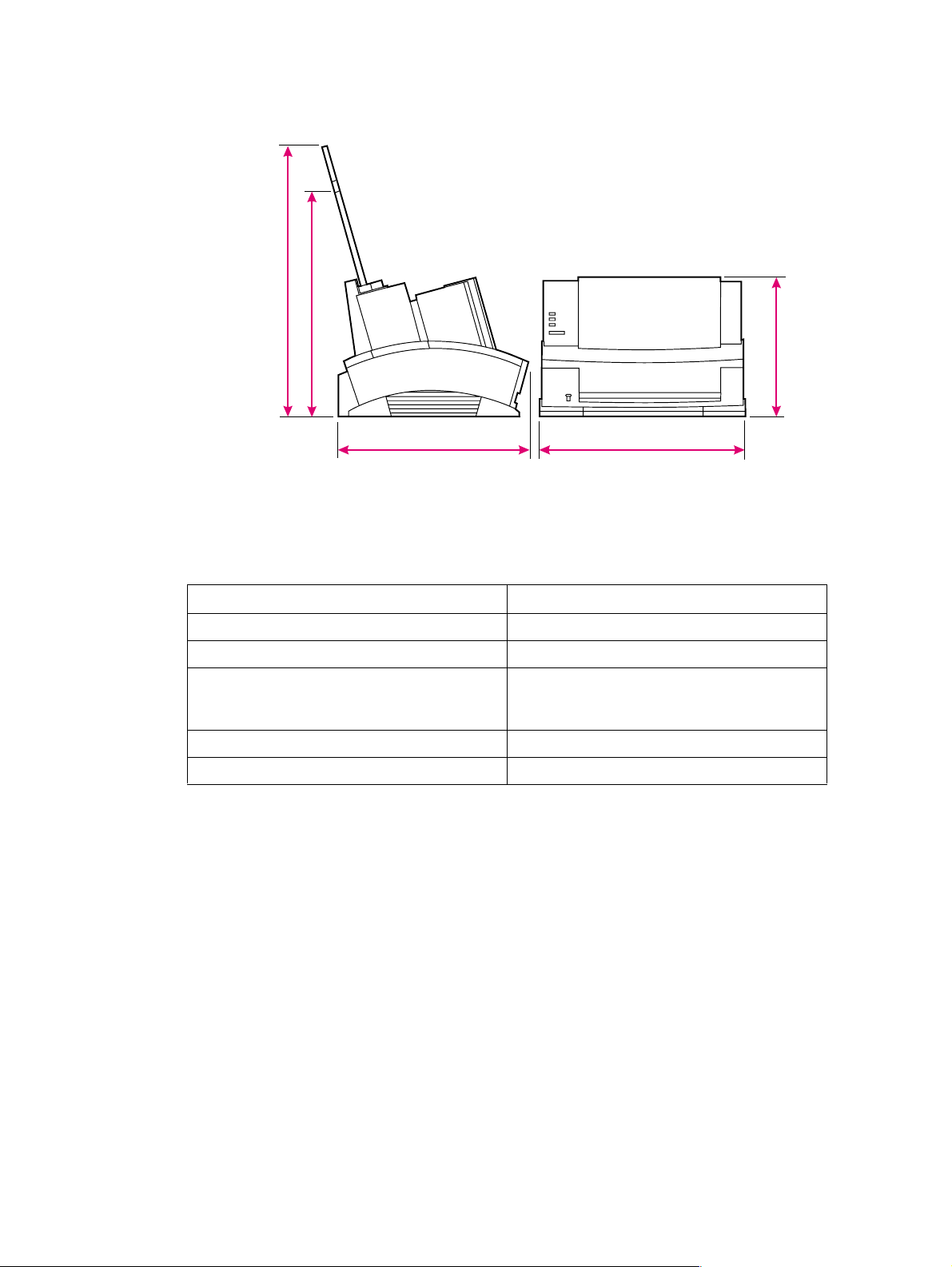
Printer space requirements
Legal (paper guide not present on HP LaserJet 6L Pro)
A4
Letter
445.3 mm
327.5 mm
Figure 2-1 Printer space requirements
227.5 mm
311.2 mm 335.5 mm
Table 2-2 Printer dimensions
Description Dimension
Width 335.5 mm (13.2 inches)
Depth 311.2 mm (12.3 inches)
Height
(storage)
(operational)
Weight (with toner cartridge) 7.2 kg (15. 9 pounds)
Toner Cartridge weight
1. With Letter Input Assembly extended.
2. Some quantity of toner will reside in the waste toner area of a Toner Cartridge when the toner supply is
exhausted. Therefore, using toner cartridge weight may be an unreliable indication of remaining toner
supply.
2
227.5 mm (8.9 inches)
372.7 mm (14.6 inches)
0.7 kg (1.5 pounds)
1
EN Printer space requirements 33
Page 36

The HP C3906A/F Toner Cartridge
Toner Cartridges contain components that are sensitive to light, temperature, and humidity. Follow
the recommendations in this section to ensure the highest quality and longest life of HP Toner
Cartridges.
Keep the printer within the following environmental conditions for optimum performance.
Storage conditions
The Toner Cartridge is affected by its environment. Packaging protects the Toner Cartridge from light
and increases its storage life. It is important to store the cartridge in its original packaging until the
cartridge is ready to be installed in the printer.
When storing the Toner Cartridge in a warehouse or work area, make sure the storage place meets
the conditions specified in Table 2-1.
Storing opened toner cartridges
Because the cartridge does not have a shutter to cover the laser beam access slot, it should be kept
inside the printer until empty. Toner Cartridges that have had the toner sealing tape removed are also
more vulnerable to environmental extremes (such as high humidity).
If the toner cartridge must be removed from the printer, always store the cartridge:
l Inside the protective bag in which it was originally packaged.
l In a dark cabinet, away from direct sunlight.
l Correct side up and in a horizontal position (not standing on end).
l At a temperature between 32° to 104° F (0° and 40° C).
l Away from ammonia or other organic solvent fumes.
CAUTION Never ship the printer with a T oner Cartridge installed. Excessive vibration during shipping can cause
toner to leak, contaminating the printer . Never expose the Toner Cartridge to direct sunlight or to room
light for more than a few minutes. Bright light and direct sunlight can permanently damage a Toner
Cartridge.
Note The C3906F Toner Cartridge is designed specifically for use in the environmental conditions of the
Asia Pacific region and is only available in that region.
34 Site requirements EN
Page 37

Toner car tri dg e handl ing suggestio ns
l Before installing a cartridge, distribute the toner evenly by rotating the cartridge back and forth
five to six times. (See Figure 2-2.) Repeat this action when toner begins to run low.
Figure 2-2 Toner cartridge distribution
l Do not touch the surface of the Photosensitive Drum in the cartridge. Protect the drum from light
and contamination.
l Do not expose the cartridge to unnecessary vibrations or shock.
l Do not expose the Photosensitive Drum to strong light. Blurred areas on the page may indicate
that the drum has been exposed to light for too long. This causes permanent damage to the
Photosensitive Drum. Replace the cartridge.
l Never manually rotate the drum, especially in the reverse directions; internal damage and toner
spills may result.
l Remove the Toner Cartridge before shipping the printer.
EN The HP C3906A/F T oner Cartridge 35
Page 38

36 Site requirements EN
Page 39

3 Operating overview
Chapter contents
Using the Control Panel. . . . . . . . . . . . . . . . . . . . . . . . . . . . . . . . . . . . . . . . . . . . . . . . . . . . . . . . . 38
Control Panel layout . . . . . . . . . . . . . . . . . . . . . . . . . . . . . . . . . . . . . . . . . . . . . . . . . . . . . . . .38
Indicator lights. . . . . . . . . . . . . . . . . . . . . . . . . . . . . . . . . . . . . . . . . . . . . . . . . . . . . . . . . . . . . 38
The Control Panel Button . . . . . . . . . . . . . . . . . . . . . . . . . . . . . . . . . . . . . . . . . . . . . . . . . . . .40
Printing a self-test page. . . . . . . . . . . . . . . . . . . . . . . . . . . . . . . . . . . . . . . . . . . . . . . . . . . . . . . . .41
Continuous self test . . . . . . . . . . . . . . . . . . . . . . . . . . . . . . . . . . . . . . . . . . . . . . . . . . . . . . . .44
Printing an engine test. . . . . . . . . . . . . . . . . . . . . . . . . . . . . . . . . . . . . . . . . . . . . . . . . . . . . . . . . .44
Resetting the printer . . . . . . . . . . . . . . . . . . . . . . . . . . . . . . . . . . . . . . . . . . . . . . . . . . . . . . . . . . . 45
To reset the printer . . . . . . . . . . . . . . . . . . . . . . . . . . . . . . . . . . . . . . . . . . . . . . . . . . . . . . . . .45
EN Chapter contents 37
Page 40
Using the Control Panel
Control Panel layout
The Control Panel is located on the front of the printer and consists of one button and three indicator
lights.
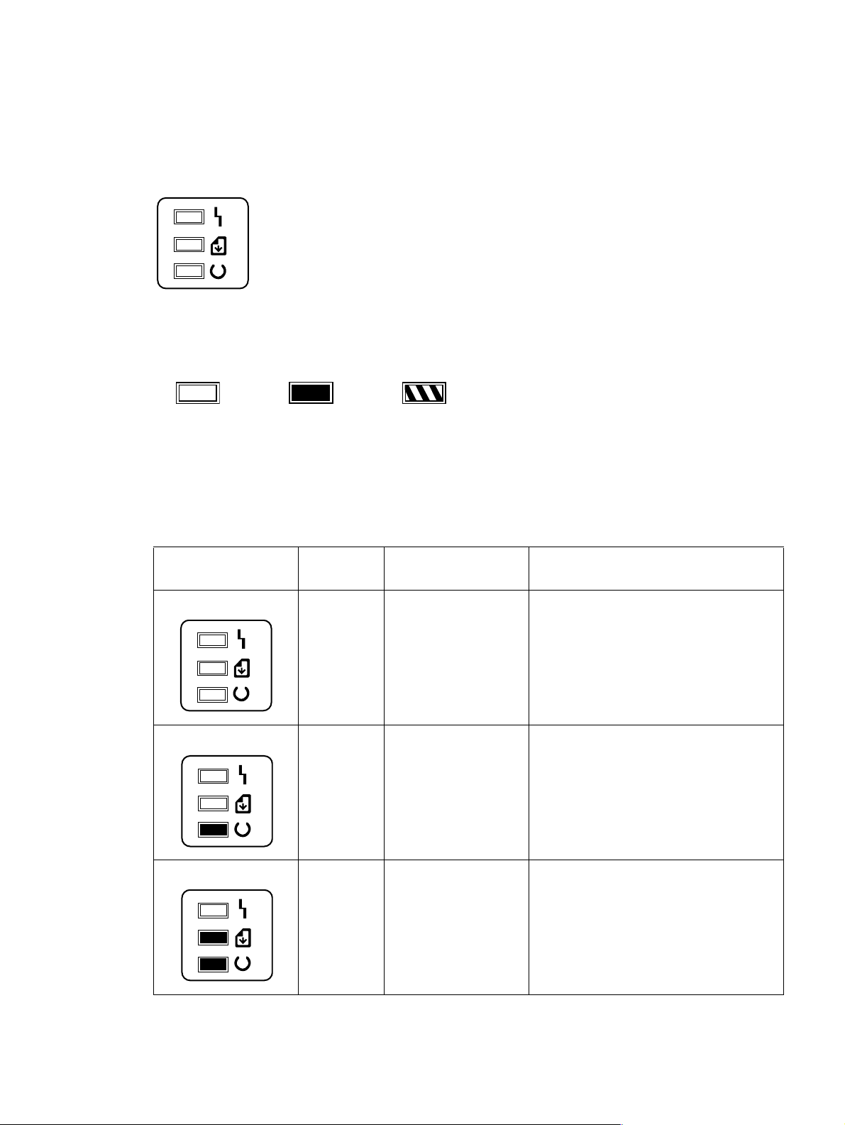
ERROR (Amber)
DATA (Green)
READY (Green)
These lights can be in only one of the following states:
OFF ON Blinking
Indicator lights
The Indicator Lights provide a quick way to check the printer’s status.
Table 3-1 Indicator Lights (1 of 2)
When this indicator: Looks
It means this: D o this:
like this:
No lights are on
or blinking
On
Blinking
Data Light and
Ready Light
both remain on
The printer is in
SleepMode or has been
disconnected.
The printer is ready to print.
Print job in progress.
Unprinted data are in the
printer.
If you want to print, press and release the Control
Panel Button or send the print job. If no response,
check the power cord.
No action is necessary. However, you can print a
test page by pressing and releasing the Control
Panel button.
Let job finish printing.
Press and release the Control Panel Button to
print the remaining data. See “Service and error
messages” in Chapter 7.
38 Operating overview EN
Page 41
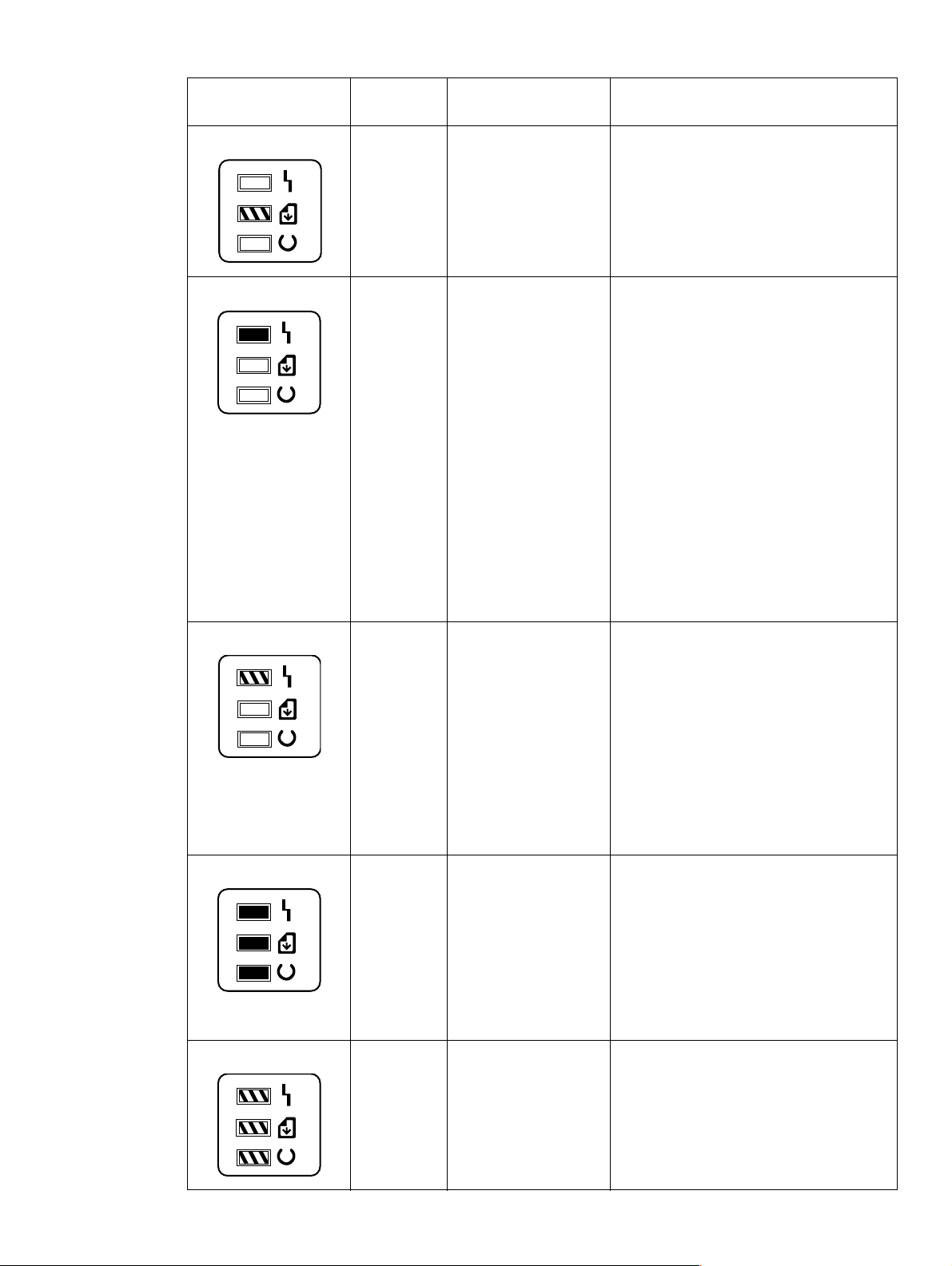
Table 3-1 Indicator Lights (Continued) (2 of 2)
When this indicator: Looks
like this:
Data Light is
blinking
Error Light
remains on
Error Light is
blinking
It means this: D o this:
Printer is in Manual Feed
mode.
Printer is out of paper.
Printer’s EP door is open.
Printer has a paper jam.
Toner Cartridge is either
missing or not installed
correctly.
The page may have too
much data or may be too
complex for the printer’s
memory capacity.
Make sure that the correct paper is loaded. Then,
press and release the Control Panel Button to
print.
Add paper.
Close the door.
Clear the jam and resume printing.
Install a cartridge, being careful to position it
correctly.
NOTE: The HP LaserJet 6L Pro has no
mechanism for detecting the presence of a Toner
Cartridge. If the Toner Cartridge is missing, the
Error Light will remain off. Printing without a Toner
Cartridge installed may cause a paper jam.
If the Error Light remains lit after checking for
these problems, and there’s no paper jam,
disconnect the power for 10 seconds, then
reconnect to the power source. If, after taking
these actions, the light remains on, refer to
Chapter 7, “Troubleshooting.”
Press and release the Control Panel Button to
continue printing. There may be some data loss
on the page.
Hint: To avoid this in the future:
All lights remain onPrinter is indicating either
All lights are
blinking
an internal problem or a
fatal error.
Printer is initializing or
resetting (6L Pro)
Memory card may be
slower than 70 nsec
(5L/6L)
1. See your printer driver help for more
suggestions regarding printer memory usage.
2. Reduce resolution to 300 dpi with your
software.
3. Install additional printer memory. (See Chapter
6 for information on installing additional memory.)
1. If you have added an additional memory card,
try removing it.
2. Disconnect the power for 10 seconds, then
reconnect it.
3. If all of the lights come on steadily again, try
disconnecting the power for 15 minutes.
If this error remains after completing the tasks
above, see Chapter 7, “Troubleshooting.”
No action is necessary.
See Chapter 7, “Troubleshooting.”
EN Using the Control Panel 39
Page 42

The Control Panel Button
Depending on what state the printer is in, pressing the Control Panel Button allows you to control
printing tasks by either starting or resuming a printer function. Use the Control Panel Button to
accomplish the following tasks:
Table 3-2 Control Panel Button usage
Function Lights Action Result
Wake Up All lights are off while
plugged into power source
Self Test Ready (bottom) Light is on
and the other lights are off.
Printer Reset The Ready (bottom) Light
will remain lit, if there are no
printer errors.
Resume (from Manual
Feed)
Continue (from
memory error)
Form Feed The Data (middle) Light and
The Data (middle) Light
blinks.
Error (top) Light blinks. Briefly push and release the
the Ready (bottom) Light
both remain on.
Briefly push and releas e the
button.
Briefly push and releas e the
button.
Press and hold the button
until the three Front Panel
Lights blink quickly in
succession.
Briefly push and releas e the
button.
button.
Briefly push and releas e the
button.
The printer will w ake up to a
ready state.
Prints a self-test page.
The reset will return the
printer to the factory default
settings. This clea rs all dat a
from memory, including any
downloaded fonts and
macros.
Override manual feed to
print from paper cassette.
Allows the printer to reco v e r
and continue printing the
job.
The remaining data in
printer memory will print.
40 Operating overview EN
Page 43
Printing a self-test page
A self-test page can be useful in troubleshooting printer problems and determining which fonts have
been downloaded to the printer.
Figure 3-1 Self-test page for HP LaserJet 5L
EN Printing a self-test page 41
Page 44
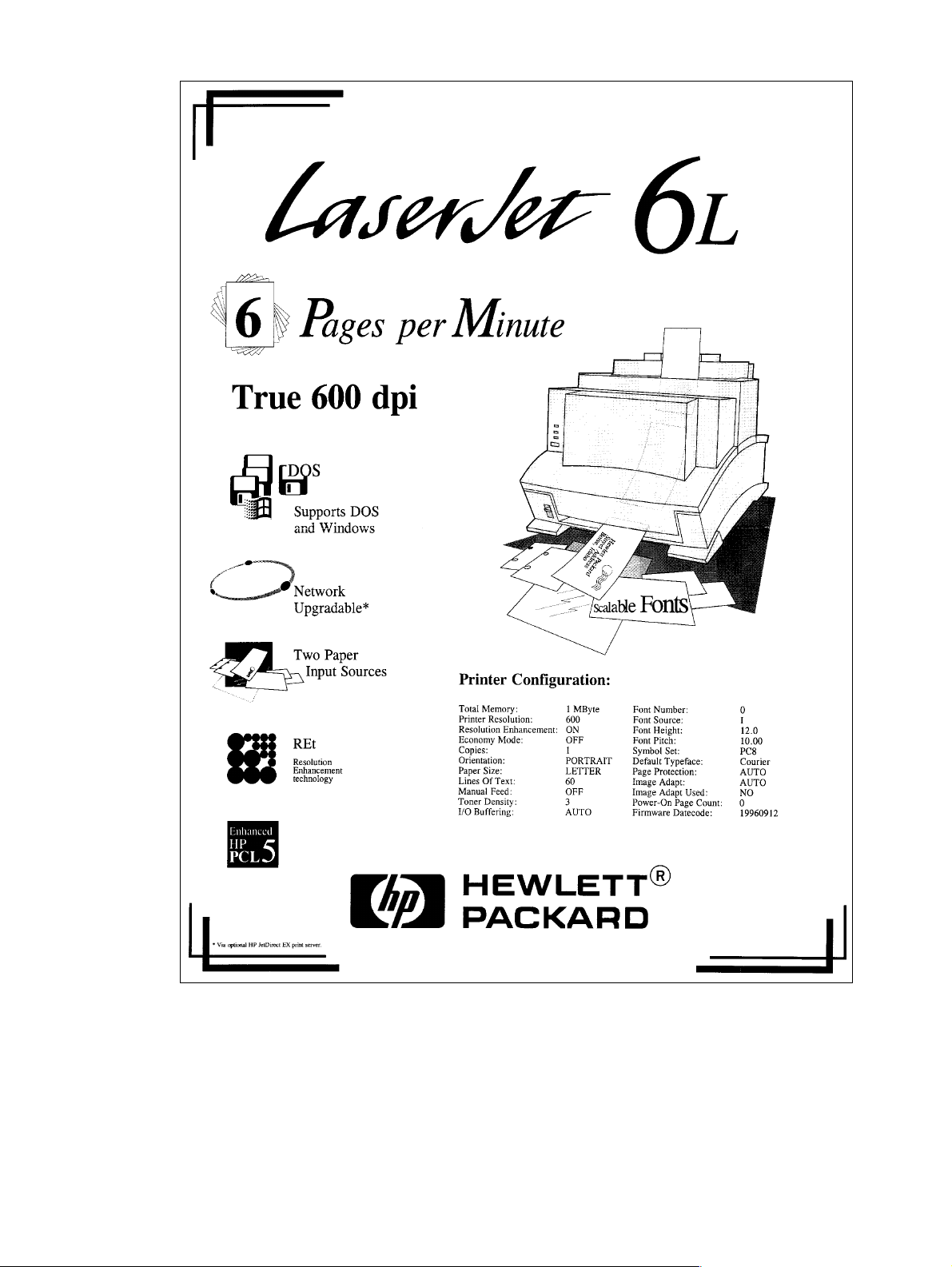
Figure 3-2 Self-test page for HP LaserJet 6L
42 Operating overview EN
Page 45
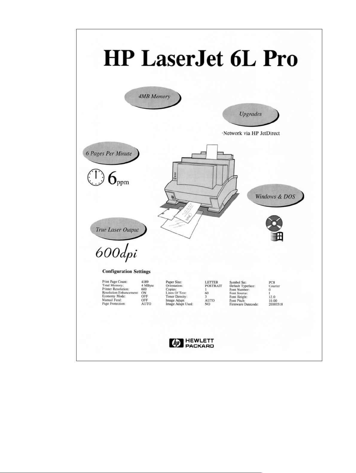
Figure 3-3 Self-test page for HP LaserJet 6L Pro
The self-test page lists the current printer configuration. (If any fonts have been downloaded to the
printer a second page will print.)
To print a self-test page:
1 Make sure the Ready (bottom) Light is on, and all other lights are off. Wake up the printer if
necessary by pressing the Control Panel Button.
2 Briefly press and release the Control Panel Button. The Data (middle) Light comes on, the
Ready (bottom) Light blinks. Wait for a self-test page to print.
EN Printing a self-test page 43
Page 46
Continuous self test
Note The HP LaserJet 6L Pro does not support the continuous self test.
A continuous self test can be useful for troubleshooting paper path and other problems. To print a
continuous self test:
1 Disconnect the printer from the power source.
2 Press and hold down the Control Panel Button while connecting power.
3 Continue holding the button for about five seconds.
All lights will illuminate at once, then each will light in sequence.
4 Release the button. The printer conducts its internal diagnostics routine, then prints the self-test
page continuously until stopped.
5 To stop the continuous self test (and reset the printer), press and hold the Control Panel Button
for a few seconds until all lights begin lighting in sequence once again.
Note The self test does not print at the printer’s rated speed of 4 ppm (HP LaserJet 5L) or 6 ppm
(HP LaserJet 6L). The engine test prints at the printer’s rated speed.
Printing an engine test
The engine test print can be used to verify that the print engine is functioning correctly. The Formatter
PCA is completely bypassed during an engine test. Consequently, this test is useful for isolating
engine printer problems. For the HP LaserJet 5L and 6L printers, the engine test prints a full page of
vertical lines down the entire printable area. For the HP LaserJet 6L Pro, the engine test prints a full
page of horizontal lines across the entire printable area. These engine test pages are useful for
checking and adjusting registration.
Note Perform the engine test with the printer covers in place, as shown in Figure 3-6. Refer to “Engine T est”
in Chapter 7 for the engine test procedure.
Engine test printout
(5L/6L)
(6L Pro)
Engine test buttonEngine test printout
Figure 3-4 Engine test button
44 Operating overview EN
Page 47

Resetting the printer
Resetting the printer accomplishes the following:
l Clears all data from the printer’s memory (including unprinted data, downloaded fonts, and
macros).
l Stops any printing that is taking place and ejects the page.
l Removes some error conditions.
l Resets the printer to its factory default settings.
To reset the printer
Press and hold the Control Panel Button until the three Control Panel Lights blink quickly in
succession (about five seconds), then let go of the button. After resetting, the Ready Light will
remain lit if there are no printer errors. (Make sure there is paper in the printer or the Error Light will
remain lit.)
EN Resetting the printer 45
Page 48

46 Operating overview EN
Page 49

4 Printer maintenance
Chapter contents
Life expectancy of consumables . . . . . . . . . . . . . . . . . . . . . . . . . . . . . . . . . . . . . . . . . . . . . . . . . .48
Toner cartridge life. . . . . . . . . . . . . . . . . . . . . . . . . . . . . . . . . . . . . . . . . . . . . . . . . . . . . . . . . . . . . 49
Saving toner with EconoMode . . . . . . . . . . . . . . . . . . . . . . . . . . . . . . . . . . . . . . . . . . . . . . . .49
Refilled toner cartridges . . . . . . . . . . . . . . . . . . . . . . . . . . . . . . . . . . . . . . . . . . . . . . . . . . . . .50
Recycling toner cartridges . . . . . . . . . . . . . . . . . . . . . . . . . . . . . . . . . . . . . . . . . . . . . . . . . . .50
Cleaning the printer. . . . . . . . . . . . . . . . . . . . . . . . . . . . . . . . . . . . . . . . . . . . . . . . . . . . . . . . . . . . 51
Cleaning printer components . . . . . . . . . . . . . . . . . . . . . . . . . . . . . . . . . . . . . . . . . . . . . . . . .51
Cleaning spilled toner . . . . . . . . . . . . . . . . . . . . . . . . . . . . . . . . . . . . . . . . . . . . . . . . . . . . . . . 52
EN Chapter contents 47
Page 50

Life expectancy of consumables
Always inspect the components listed in Table 4-1 for wear when servicing the printer. Replace these
components as needed, based on printer failures or wear, not strictly on usage.
Table 4-1 Life expectancy of consumables
Description Estimated Life
Remarks
(pages)
Toner cartridge (user replaceable) 2,500
Transfer roller 50,000 May affect print quality and/or paper
Paper pickup assembly 50,000 Look for glazing and/or cracks.
Separation pad and sub pads 50,000 May affect paper movement.
Heating Element 100-120 V, 50/60 Hz
220-240 V, 50 Hz
Pressure Roller
1. The estimated toner cartridge life is based on Letter or A4 size paper with an average of five percent toner coverage and a medium density setting. Toner cartridge life can be extended further by conserving toner using the printer’s EconoMode feature.
1
50,000 May affect print quality and/or paper
When print becomes faint, shake cartridge to
distribute remaining toner.
movement.
movement. Look for marks on pressure roller
or upper Teflon sleeve.
48 Printer maintenance EN
Page 51
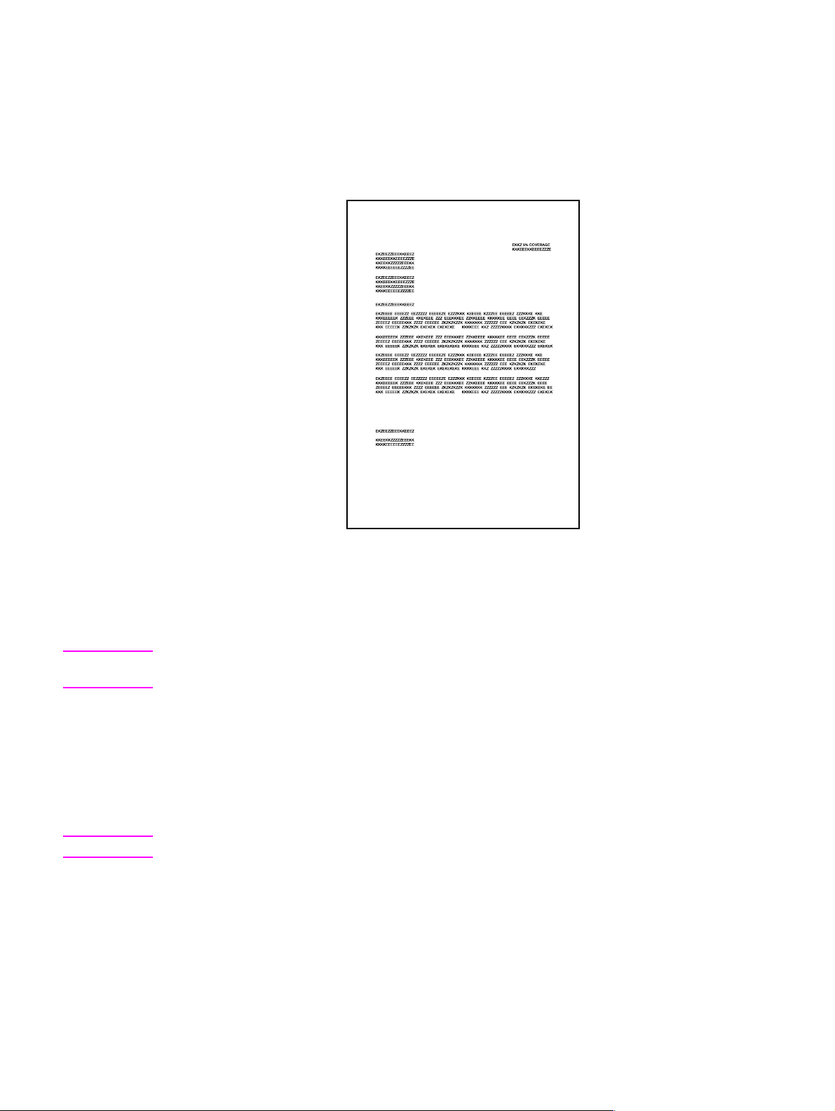
Toner cartridge life
The toner cartridge has been designed to simplify the replacement of the printer’s major parts. The
toner cartridge contains the printing mechanism and a supply of toner. When using a typical wordprocessing application, a toner cartridge will print approximately 2500 pages where the text covers
about five percent of the page.
Figure 4-1 Five percent text coverage
When regularly printing pages with less coverage, such as short memos, a toner cartridge should
print over 2,500 pages. However, if routinely printing very dense print, the cartridge will not print a full
2,500 pages.
Note For best results, always use a toner cartridge before the expiration date stamped on the toner cartridge
box.
Saving toner with EconoMode
Toner cartridge life can be extended dramatically by using the EconoMode printing feature of the
printer. EconoMode uses approximately 50 percent less toner than normal printing. The printed page
is much lighter and is adequate for printing drafts or proofs. EconoMode can be set through your
printer driver. See Chapter 5 for more information.
Note Some software applications may refer to this as “draft mode.”
EN T oner cartridge life 49
Page 52

Refilled toner cartridges
While Hewlett-Packard does not prohibit the use of refilled toner cartridges during the warranty
period or while under a maintenance contract, we do not recommend their use. The reasons for this
are:
l Hewlett-Packard has no control or process to ensure that a refilled toner cartridge functions at
the high level of reliability of a new HP LaserJet toner cartridge.
l Hewlett-Packard also cannot predict what the long-term reliability effect on the printer is from
using different toner formulations found in refilled cartridges.
l Hewlett-Packard has no control over the actual print quality of a refilled toner cartridge. The print
quality of HP LaserJet toner cartridges influences the customer’s perception of the printer.
Repairs resulting from the use of refilled toner cartridges are not covered under the HP warranty or
maintenance contract.
Recycling toner cartridges
In order to reduce waste, Hewlett-Packard has adopted a recycling program for used toner
cartridges. Plastics and other material are recycled. Cartridge components that do not wear out are
reused. HP pays the shipping costs from the user to the recycling plant. To join this recycling effort,
follow the instructions inside the toner cartridge box.
50 Printer maintenance EN
Page 53

Cleaning the printer
To maintain the print quality, thoroughly clean the printer:
l Every time you change the toner cartridge.
l After printing approximately 2,500 pages.
l Whenever print quality problems occur.
Clean the outside of the printer with a lightly water-dampened cloth. Clean the inside with only a dry ,
lint-free cloth. Observe the warnings and cautions below.
WARNING! Before you begin these steps, unplug the printer to avoid shock hazard.
When cleaning around the front door area, avoid touching the heating element. It may be HOT.
(For heating element location, see Figure 6-14.)
Cleaning printer components
CAUTION T o av oid permanent damage to the toner cartridge, do not use ammonia-based cleaners on or around
the printer. Do not touch the transfer roller with your fingers. Contaminants on the roller can cause print
quality problems.
Table 4-2 Cleaning printer components
Component Cleaning Method/Notes
Outside Cove rs Use a water-dampened cloth. Do not use solvents or ammonia-based
cleaners.
Inside General Use a dry, lint free cloth. Remove all dust, spilled toner, and paper particles.
Exit Roller Use a water-dampened lint-free cloth.(For location, see Figure 6-8.)
Fuser Exit Roller Use a water-dampened lint-free cloth. (For location, see Figure 6-18.)
Pickup Roller Use a lint-free cloth dampened with isopropyl alcohol. (For location, see
Figure 6-25.)
Pressure Roller Use a dry lint-free cloth. (For location, see Figure 6-16.)
Transfer Roller Use a dry, lint-free cloth. DO NOT TOUCH with your fingers. (For location,
see Figure 6-30.)
Separation Pad Use a dry lint-free cloth. (For location, see Figure 6- 31.)
Delivery Assembly Use a water-dampened lint-free cloth. (For location, see Figure 6-10.)
Static Eliminator Teeth Use compressed air. (See Figure 4-2 on the following page for s tatic
eliminator teeth location.)
EN Cleaning the printer 51
Page 54
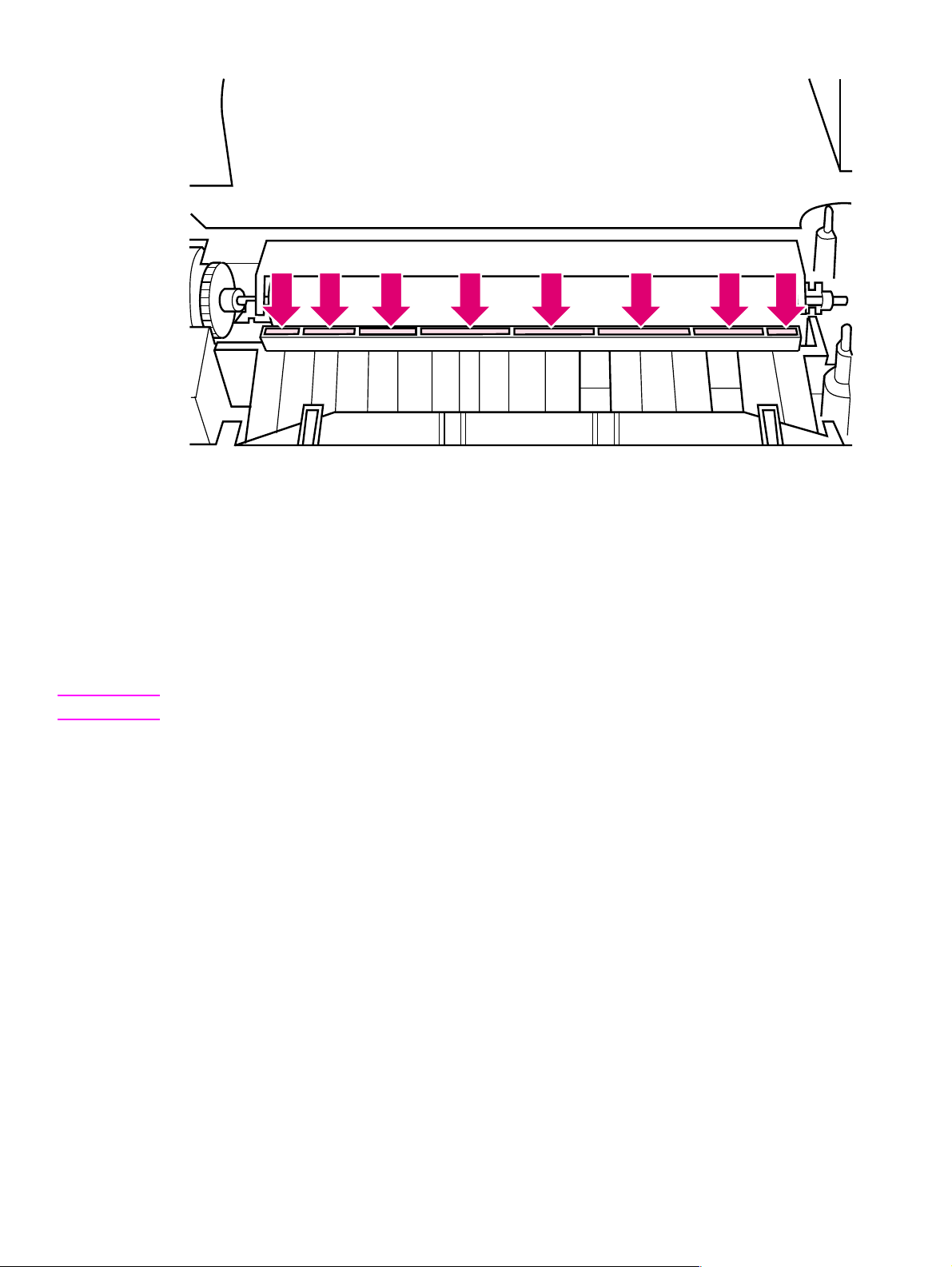
Figure 4-2 Static Eliminator Teeth (located in front of the transfer roller)
Cleaning spilled toner
Defective toner cartridges can develop leaks. In addition, after a paper jam has occurred, there may
be some toner remaining on the rollers and guides inside the printer . The pages that print
immediately after the jam may pick up this toner.
Clean spilled toner with a cloth slightly dampened in cold water. Do not touch the Transf er Roller with
the damp cloth or with your fingers. Do not use a vacuum cleaner unless it is equipped with a microfine particle filter.
Note If toner gets on your clothing, use cold water to remove it. Hot water sets toner stains into fabric.
52 Printer maintenance EN
Page 55

5 Functional overview
Chapter contents
Basic printer functions. . . . . . . . . . . . . . . . . . . . . . . . . . . . . . . . . . . . . . . . . . . . . . . . . . . . . . . . . . 54
DC Controller/power system . . . . . . . . . . . . . . . . . . . . . . . . . . . . . . . . . . . . . . . . . . . . . . . . . . . . . 55
Print engine control system . . . . . . . . . . . . . . . . . . . . . . . . . . . . . . . . . . . . . . . . . . . . . . . . . .56
Power system (on DC Controller PCA). . . . . . . . . . . . . . . . . . . . . . . . . . . . . . . . . . . . . . . . . . 56
Formatter system . . . . . . . . . . . . . . . . . . . . . . . . . . . . . . . . . . . . . . . . . . . . . . . . . . . . . . . . . . . . .58
CPU . . . . . . . . . . . . . . . . . . . . . . . . . . . . . . . . . . . . . . . . . . . . . . . . . . . . . . . . . . . . . . . . . . . . 58
Read only memory (ROM) . . . . . . . . . . . . . . . . . . . . . . . . . . . . . . . . . . . . . . . . . . . . . . . . . . .58
Random access memory (RAM). . . . . . . . . . . . . . . . . . . . . . . . . . . . . . . . . . . . . . . . . . . . . . . 58
Parallel interface . . . . . . . . . . . . . . . . . . . . . . . . . . . . . . . . . . . . . . . . . . . . . . . . . . . . . . . . . . . 58
Control Panel . . . . . . . . . . . . . . . . . . . . . . . . . . . . . . . . . . . . . . . . . . . . . . . . . . . . . . . . . . . . .58
Resolution Enhancement technology (REt) . . . . . . . . . . . . . . . . . . . . . . . . . . . . . . . . . . . . . .59
EconoMode. . . . . . . . . . . . . . . . . . . . . . . . . . . . . . . . . . . . . . . . . . . . . . . . . . . . . . . . . . . . . . . 59
Memory Enhancement technology (MEt) . . . . . . . . . . . . . . . . . . . . . . . . . . . . . . . . . . . . . . . .59
Enhanced I/O . . . . . . . . . . . . . . . . . . . . . . . . . . . . . . . . . . . . . . . . . . . . . . . . . . . . . . . . . . . . .59
Page Protect. . . . . . . . . . . . . . . . . . . . . . . . . . . . . . . . . . . . . . . . . . . . . . . . . . . . . . . . . . . . . . 60
PJL overview. . . . . . . . . . . . . . . . . . . . . . . . . . . . . . . . . . . . . . . . . . . . . . . . . . . . . . . . . . . . . .60
Image formation system . . . . . . . . . . . . . . . . . . . . . . . . . . . . . . . . . . . . . . . . . . . . . . . . . . . . . . . . 61
Toner cartridge . . . . . . . . . . . . . . . . . . . . . . . . . . . . . . . . . . . . . . . . . . . . . . . . . . . . . . . . . . . . 61
Step 1: Drum cleaning . . . . . . . . . . . . . . . . . . . . . . . . . . . . . . . . . . . . . . . . . . . . . . . . . . . . . .62
Step 2: Drum conditioning . . . . . . . . . . . . . . . . . . . . . . . . . . . . . . . . . . . . . . . . . . . . . . . . . . .62
Step 3: Image writing . . . . . . . . . . . . . . . . . . . . . . . . . . . . . . . . . . . . . . . . . . . . . . . . . . . . . . .62
Step 4: Image developing . . . . . . . . . . . . . . . . . . . . . . . . . . . . . . . . . . . . . . . . . . . . . . . . . . . .62
Step 5: Image transferring . . . . . . . . . . . . . . . . . . . . . . . . . . . . . . . . . . . . . . . . . . . . . . . . . . .62
Step 6: Image fusing. . . . . . . . . . . . . . . . . . . . . . . . . . . . . . . . . . . . . . . . . . . . . . . . . . . . . . . .62
Paper feed system. . . . . . . . . . . . . . . . . . . . . . . . . . . . . . . . . . . . . . . . . . . . . . . . . . . . . . . . . . . . . 63
Paper jam detection . . . . . . . . . . . . . . . . . . . . . . . . . . . . . . . . . . . . . . . . . . . . . . . . . . . . . . . .65
Basic sequence of operation. . . . . . . . . . . . . . . . . . . . . . . . . . . . . . . . . . . . . . . . . . . . . . . . . . . . .66
EN Chapter contents 53
Page 56
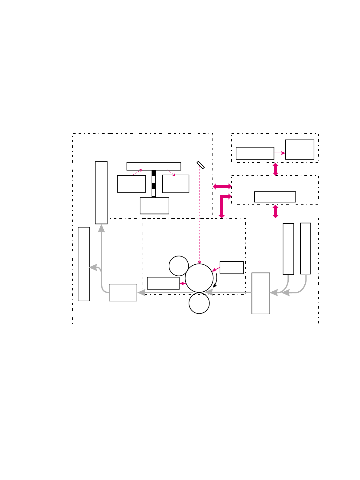
Basic printer functions
This chapter presents a generalized functional overview of the printer and the printing processes.
The following printer systems are discussed:
l DC Controller System/ Power System
l Formatter Syst em
l Image Formation System
l Paper Feed System
l Laser/Sca nner System
Figure 5-1 is a generalized block diagram of the printer:
Laser/Scanner System Formatter System
Control
Formatter
Panel
Scanning Mirror
Laser
Diode
BD
Circuit
DC Controller/Power System
DC Controller
Scanner
Motor
Paper Outpu t Bin
Image Formation
System
Primary
Charging
Roller
Front Output Slot
Fusing
Cleaner
Assembly
Photo-
sensitive
drum
Transfer
Charging
Roller
Developing
Unit
Pick-
up
Unit
Paper Input Tray
Single Sheet Input Slot
Pick Up/Feed System
Figure 5-1 Printer functional block diagram
54 Functional overview EN
Page 57
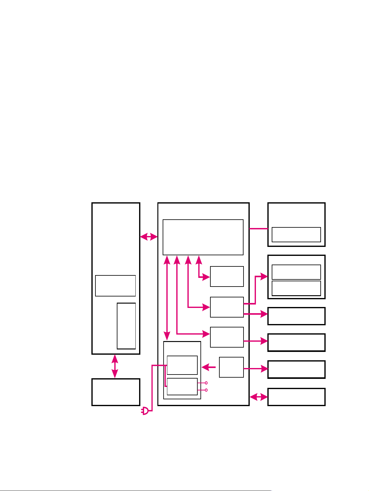
DC Controller/power system
The DC Controller PCA coordinates all print engine activities, drives the laser, and coordinates print
data from the Formatter PCA with the image formation process. The DC Controller also includes both
AC and DC power supply and distribution circuitry. The DC Controller controls the following systems
and functions:
l Print Engine Control
• Laser and Scanner Drive
• Paper Motion Photosensors (Paper Out, Paper Registration, and Paper Exit Sensors)
• Motor
l Power System
• AC Power Distribution
• DC Power Distribution
• Overcurrent/Undervoltage Protection
• SleepMode
• High Voltage Power Distribution
Figure 5-2 shows the various DC controller loads.
PCA
Memory
I/O
Control Panel
DC ControllerFormatter
Power
Supply
AC Driver
LV Power
Supply
CPU
Delivery
Paper
Sensor
HV Power
Supply
Main Motor
Drive
Fuser
Drive
Laser/Scanner
Assembly
Laser Diode
Toner Cartridge
Charging Roller
Developing Roller
Bias
Transfer Roller
Motor
Fusing Assembly
Sensors/Solenoid
Figure 5-2 DC Controller loads
EN DC Controller/power system 55
Page 58

Print engine control system
Laser and scanner drive
Based on information received from the Formatter, the DC Controller sends signals to the Laser/
Scanner Assembly to modulate the laser diode ON and OFF and to drive the Laser/Scanner motor.
Refer to “Image formation system” later in this chapter for more information.
Paper motion monitoring and control
The DC Controller PCA controls paper motion by continuously monitoring the various paper sensors
and coordinating the timing with the other print processes.
For a detailed explanation of paper movement, and the interaction of photosensors and solenoid with
the paper movement process, refer to “Paper f eed system” later in this chapter.
12 V shutoff switch
The 12 volt DC power shutoff switch, Switch 101, located on the top of the printer, is activated by the
printer door. The front door must be closed before the printer can resume printing.
Engine test switch
The Test Print, Switch 201, located on the DC Controller, is activated manually through an access
hole at the front of the printer. This switch causes the print engine to perform a self-test diagnostic
which bypasses the Formatter PCA and prints a full page of black vertical lines. This test is useful for
troubleshooting printer problems because it isolates the print engine from the Formatter PCA. (See
Chapter 7, “Troubleshooting,” to learn more about how to perform an engine test.)
Motor
The Motor is controlled by the DC Controller PCA. The Motor provides all of the printer’s paper
movement.
Power system (on DC Controller PCA)
The AC, DC, and high voltage power supply circuits are all contained within the DC Controller PCA.
AC power distribution
The AC power circuitry supplies AC voltage whenever the power cord is connected to the AC power
source. AC voltage is distributed to the DC power supply circuitry and to the AC driver circuitry, which
controls AC voltage to the fusing assembly’s heating element.
56 Functional overview EN
Page 59

DC power distribution
The DC power distribution circuitry, located on the DC Controller PCA, distributes +5 V DC and +12
V DC as follows:
+5 V DC l Formatter PCA
l Photosensors
l DC Controller Circuitry
l Laser/Beam Detect Circuitry
+12 V DC:
+12 VA DC l High Voltage Power Supply
l Motor
l Scanne r Motor
l Solenoid
Overcurrent/overv oltage pr otection
There are two overvoltage/overcurrent devices in this printer:
l Fuse F101 provides overcurrent protection for the fusing system circuitry. To check or replace the
fuse requires the removal of the DC Controller. Fuse 102 (found only on 110V units) provides
overcurrent protection to the printer DC power supply circuitry.
l In addition, the +12V DC and +5V DC power circuitry contains an overcurrent protection circuit
that automatically shuts off the output voltage when an overcurrent condition occurs due to a
short or abnormal voltage on the load side.
SleepMode
Instead of a power switch, the printer has a SleepMode function. After the printer has been idle for 15
minutes, it turns itself off by shifting to SleepMode. The Control Panel lights remain off, and the
printer retains all printer settings and downloaded fonts and macros while in SleepMode.
The printer exits SleepMode and all of the lights power on when any of the following occur:
l A job is received.
l The Control Panel Button is pressed.
l The printer front door is opened.
Note The printer will not enter SleepMode if there is a printer error.
High voltage power distribution
The High Voltage Power Supply PCA applies an overlap of DC and AC voltage to the primary
charging roller and the developing roller. This circuit also applies a positive or negative DC voltage to
the transfer charging roller according to the instructions from the CPU on the DC Controller PCA.
This circuit also controls the image density by changing the primary AC voltage and the developing
AC bias according to the setting of the print density dial.
High voltage is disabled when the printer’s EP Door is open (i.e., switch SW101 is open).
EN DC Controller/power system 57
Page 60

Formatter system
The Formatter PCA is responsible for the following:
l Receiving and processing print data from the printer interface.
l Monitoring Control Panel Button and relaying printer status information.
l Developing and coordinating data placement and timing with the print engine.
l Storing font information.
l Communicating with the host computer through the Bi-Directional Interface.
The Formatter PCA receives print data from the Bi-Tronics Interface and converts it into a dot image.
The DC Controller synchronizes the Image Formation System with the Paper Feed System and
signals the Formatter to send the print image data. The Formatter sends the print image data (dots)
in the form of a VIDEO signal and the printing process begins.
On the HP LaserJet 5L and 6L, the Formatter PCA also provides mounting locations for additional
memory.
CPU
The Formatter PCA incorporates a microprocessor operating at a minimum of 24 MHz.
Read only memory (ROM)
Besides storing microprocessor control programs, the ROM stores dot patterns of internal character
sets (fonts).
Random access memory (RAM)
The RAM stores printing and downloaded font information received from the host system and
temporarily stores a full page of print image data before the data is sent to the print engine. (See
“Page Protect” later in this chapter.) F or the HP LaserJet 5L and 6L printers, memory capacity can be
increased by adding a DRAM memory card to the Formatter PCA. Note that adding memory may
also increase print speed when printing complex graphics. The HP LaserJet 6L Pro does not support
memory expansion or the use of a JEDIA card.
Parallel interface
The Formatter PCA receives incoming data through its Bi-Tronics interface. The Bi-Tronics I/O
provides high speed and two-way communication between the printer and the host, allowing the user
to change printer settings and monitor printer status from the host computer. This interface is IEEE1284 compliant.
Control Panel
Status LED lights
The Formatter uses three LEDs mounted under the printer cover to communicate printer status to the
user. Refer to “Using the Control Panel” in Chapter 3 and “Printer Error Tr oubleshooting” in Chapter 7
for more information on the lights.
Control Panel Button
The Control Panel Button is used for such functions as self test, reset, and to display error codes.
Refer to “Using the Control Panel” in Chapter 3 for more information on the Control Panel Button.
58 Functional overview EN
Page 61

Resolution Enhancement technology (REt)
The Formatter PCA contains circuitry for Resolution Enhancement technology (REt), which modifies
the standard video dot data on its way to the DC Controller to produce smoothed black-to-white
boundaries. REt is user-adjustable from some software applications. Available settings are On or Off.
EconoMode
The EconoMode setting uses approximately 50 percent less toner than standard mode printing by
reducing the dot density. However, EconoMode does not extend toner cartridge component life.
EconoMode, which can also be thought of as “draft mode,” is user-selectable through some software
applications. The default setting is Off.
Normal mode,
medium density
EconoMode,
medium density
Figure 5-3 EconoMode vs. Normal Mode
Note EconoMode does not affect print speed or memory usage.
Memory Enhancement technology (MEt)
The Hewlett-Packard Memory Enhancement technology (Met) effectively doubles the standard
memory through a variety of font and data compression methods. MEt is only available in PCL mode
and is not customer selectable. When using the host-based driver, your PC handles memory
management.
Enhanced I/O
The Enhanced I/O feature allows printer memory to be used for storing data received from the host
computer. When Enhanced I/O is enabled, you can send more data to your printer in shorter
amounts of time, which allows you to return to your application sooner. Enhanced I/O has the
following options:
l Auto allows the printer to use Enhanced I/O memory allocation to increase the speed of data
transfer from the host computer to the printer, if necessary.
l Off uses the minimum amount of printer memory for storing data sent from the host computer.
Enhanced I/O is only available in PCL mode. When using the host-based driver (HP LaserJet 5L and
6L only), your PC handles memory management.
EN Formatter system 59
Page 62

Page Protect
Page complexity (rules, complex graphics, or dense text) may exceed the printer‘s ability to create
the page image fast enough to keep pace with the Image Formation process. If Page Protect is
disabled and a page is too complex, the page may print in parts (for example, the top half on one
page and the bottom half on the next page). Some print data loss is likely in these instances, and the
printer will display an error message.
Page Protect allows the Formatter to create the entire page image in page buffer memory before
physically moving the paper through the printer. This process ensures that the entire page will be
printed. Page Protect applies only to PCL printing. The default setting is Auto.
PJL overview
Printer Job Language (PJL) is an integral part of configuration, in addition to the standard Printer
Command Language (PCL). With standard Centronics cabling, PJL allows the printer to perform
functions such as:
l T wo-wa y communication with the host computer through a Bi-directional Parallel connection. The
printer can tell the host such things as the control panel status.
l Isolation of print environment settings from one print job to the next. For example, if a print job is
sent to the printer in landscape mode, the subsequent print jobs print in landscape only if they
are formatted for landscape printing.
60 Functional overview EN
Page 63

Image formation system
Laser printing requires the interaction of several different technologies (such as electronics, optics,
and electrophotographics) to provide a printed page. Each process functions independently and
must be coordinated with the other printer processes. Image formation consists of six processes:
Step 1 Drum Cleaning
Step 2 Drum Conditioning
Step 3 Image Writing
Step 4 Image Developing
Step 5 Image Transferring
Step 6 Image Fusing
Electrostatic Latent Image Formation Block
Flow of Paper
1. Primary Charging
Drum Cleaning
Block
Paper Delivery
7. Drum Cleaning
Fuser Block
6. Fusing
Figure 5-4 Image formation block diagram
Toner car t ridge
As the “heart” of the Image Formation System, the toner cartridge houses the cleaning, conditioning,
and developing steps of the process. The toner cartridge contains the photosensitive drum, primary
charging roller, developing station, toner cavity, and cleaning station. Including these components,
which wear, degrade, or are consumed in the replaceable toner cartridge, eliminates the need for a
service call when replacement is required. The special photosensitive properties of the drum allow
an image to be formed on the drum surface and then transferred to paper.
2. Scanning Exposure
5. Separation
Transfer Block
4. Transfer
3. Developing
Registration
Direction of Drum
Manual Feeding Slot
Multi-Purpose Tray
CAUTION The printer’s toner cartridge does not include a light-blocking shutter. Be careful to avoid exposing the
drum to light, which can permanently damage the drum. Protect the cartridge whenever removing it
from the printer.
EN Image formation system 61
Page 64

Step 1: Drum cleaning
The cleaning blade is in contact with the surface of the drum at all times. As the drum rotates during
printing, excess toner wiped off and stored in the waste toner receptacle.
Step 2: Drum conditioning
After the drum is physically cleaned, it must be conditioned. This process consists of applying a
uniform negative charge on the surface of the drum with the primary charging roller, located in the
toner cartridge. The primary charging roller is coated with conductive rubber. An AC bias is applied to
the roller to erase any residual charges from any previous image. In addition, a negative DC bias is
applied by the charging roller to create a uniform negative potential on the drum surface. The amount
of DC voltage is modified by the print density setting.
Step 3: Image writing
During the writing process, a modulated laser diode projects the beam onto a rotating scanning
mirror. As the mirror rotates, the beam reflects off the mirror, first through a set of focusing lenses, off
a mirror, and finally through a slot in the top of the toner cartridge, and onto the photosensitive drum.
The beam sweeps the drum from left to right, discharging the negative potential wherever the beam
strikes the surface. This creates a latent electrostatic image, which later is developed into a visible
image.
Because the beam is sweeping the entire length of the drum and the drum is rotating, the entire
surface area of the drum can be covered. At the end of each sweep, the beam strikes the beam
detect lens, generating the Beam Detect Signal (BD). The BD signal is sent to the DC Controller,
where it is converted to an electrical signal used to synchronize the output of the next scan line of
data.
Step 4: Image developing
At this stage of the process, the latent electrostatic image is present on the drum. The toner particles
obtain a negative surface charge by rubbing against the developing cylinder, which is connected to a
negative DC supply. The negatively charged toner is attracted to the discharged (exposed,
grounded) areas of the drum, and repelled from the negatively charged (non-exposed) areas.
Step 5: Image transferring
During the transferring process, the toner image on the drum surface is transferred to the paper. A
positive charge applied to the back of the paper by the transfer roller causes the negatively charged
toner on the drum surface to be attracted to the paper. After separation, the drum is cleaned and
conditioned for the next image.
Step 6: Image fusing
During the fusing process, the toner is fused into the paper by heat and pressure to produce a
permanent image. The paper passes between a heated fusing element and a soft pressure roller.
This melts the toner and presses it into the paper.
62 Functional overview EN
Page 65
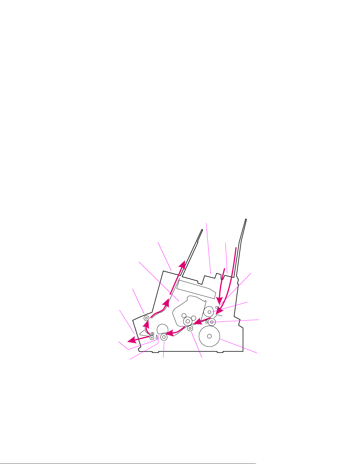
Paper feed system
Both the Paper Input Tray and the Single Sheet Input Slot merge into one, main input area. Paper
placed in either of these areas enables the Paper Out Sensor (sensor 202), which informs the DC
Controller that paper is present.
When the printer receives a print job and is ready to print, the DC Controller enables the Laser/
Scanner Assembly and the Motor. Paper motion begins when the DC Controller energizes solenoid
SL1. This causes the paper pick up roller to rotate once. Two actions occur as a result of this rotation.
First, the paper kick plate pushes the paper against the pick-up roller. Second, the pick-up roller
grabs the top sheet and advances it to the Feed Assembly drive rollers. To ensure that only one
sheet is fed, a main separation pad, along with two subpads, hold the remainder of the stack in place.
The feed assembly drive rollers advance the paper to the Paper Registration photosensor (PS203).
This sensor informs the DC Controller of the exact location of the paper’s leading edge, so that the
image being written on the photosensitive drum can be precisely positioned on the page. The feed
assembly drive rollers then advance the paper to the transfer area where the toner image on the
photosensitive drum is transferred to paper.
After the image is transferred, the paper enters the fusing assembly where heat from the fuser and
pressure from the Pressure Roller permanently bond the toner image to paper. The Paper Exit
Sensor (PS201) determines that paper has successfully moved out of the fusing area. The fusing
assembly exit rollers deliver paper to either the Output Paper Bin or the Front Output slot, depending
upon the position of the Face-up/Face-down lever.
Figure 5-5 shows a simplified paper path and the locations of the photosensors and rollers.
Paper Output Bin
Toner Cartridge
Delivery Roller #1
Front Output Slot
Paper Exit
Sensor
(PS201)
Heating Element
Manual Input Slot
Pressure Roller Transfer Roller
Paper
Input
Bin
Paper Out Sensor
(PS202)
Pick-up Roller
Paper Registration
Sensor
(PS203)
Main Motor
Figure 5-5 Simplified paper path
EN Paper f eed system 63
Page 66
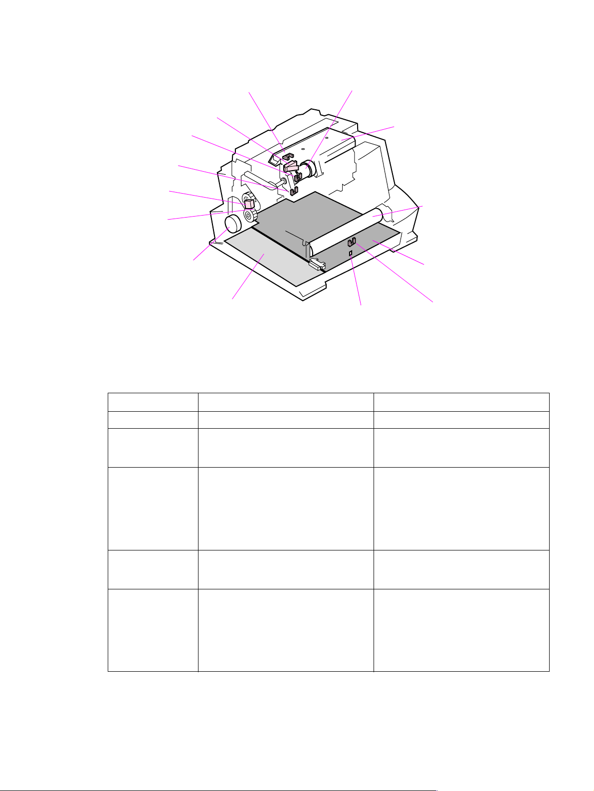
Figure 5-6 shows the locations of the photosensors, switches, solenoid, and other important printer
elements. Table 5-1 describes the function of each photosensor and the solenoid.
SW101
PS202
PS203
SL1
Drive Unit
Main Motor
Formatter
Figure 5-6 Solenoid and sensors
PS204 (5L only)
Pick-up Roller Assembly
Laser Scanner
Heating Element
DC Controller
SW201
PS201
Table 5-1 Solenoid and sensors
Number Name Description
SL1 Paper Pick-up Solenoid Enables the Paper Pickup Roller.
PS201 Paper Exit Sensor Senses when paper has successfully
moved out of the fusing area and the next
sheet of paper can be fed.
PS202 Paper Out Sensor Senses no paper in either the Paper Input
Tray or Manual Input Slot. If this sensor
does not sense paper in the Input P a per
Tray or the Single-Sheet Input Slot, the
formatter display s the pap er-ou t indi ca tion
on the Control Pane l. Paper must be
reloaded before printing can resume.
PS203 Paper Registration Sensor Detects the leading and trailing edges of
the paper. Syn chroniz es the photos ensitiv e
drum and the top of the paper.
PS204 Door Open/C a rtridge Sensor (HP LaserJet
5L only) In the HP LaserJet 6L, SW101
performs the function of 5L’s PS204. The
6L Pro has no toner cartridge sensor.
Detects whether printer door is open and
cartridge is in place. If the door is open or
the cartridge is not in place, the control
panel LEDs will display an error message.
Printing cannot continue until the door is
closed and the cartridge is in proper
position.
64 Functional overview EN
Page 67

Paper jam detection
The Paper Out Sensor (PS202), Paper Registration Sensor (PS203), and the Paper Exit Sensor
(PS201) detect when paper is moving through the printer. (See Figure 5-5 for roller and sensor
locations.) If a paper jam is detected, the DC Controller immediately stops the printing process and
causes a paper jam indication on the Control Panel.
A paper jam can be detected under any of the following conditions:
l Power-On Jams. Paper is present under either PS201 or PS203 at power-on.
l Pickup Jams. Paper does not reach and clear photosensor PS203 within a specified period of
time. The time period begins when the Paper Pickup Solenoid (SL1) is energized.
l Delay Jams. Paper does not reach or clear a specific photosensor within a specified period of
time.
EN Paper f eed system 65
Page 68

Basic sequence of operation
The Formatter PCA and the DC Controller PCA share information during printer operation. The DC
Controller-to-Formatter Connector (J201) forms a link that operates as a serial data bus. This allows
printer status, command information, and dot-image data to be passed between the two PCAs.
Figure 5-7 shows the general timing of the printer events. The f ollowing events take place during
normal prin ter operation:
Table 5-2 Printer timing
Period Timing Purpose
WAIT From when the paper is inserted to the end
of Main Motor initial rotation.
STBY (standby) From the end of the WAIT or the LSTR
period until the input of the PRNT signal
from the Formatter. Or from the end of the
LSTR period until power OFF.
INTR (initial rotation) From the input of the PRNT signal from the
Formatter until the la ser diode int ensity has
been stabilized.
PRNT From the end of initial rotation until the
Scanner Motor stops.
LSTR (last rotation) From the primary voltage (DC) OFF until
the Main Motor stops.
If another PRNT signal is sent from the
Formatter, the printer returns to the INTR
period. If not, it returns to the STBY period.
Refer to the Timing Diagrams on the following pages.
Clear the drum surf ac e po ten tia l an d c lea n
the Transfer Roller.
Maintain the printer in ready state.
Stabilize the photosensitive drum
sensitivity in preparation for printing. Also
clean the Transfer Roller.
Form images on the photosensitive drum
based on the /VDO signal from the
Formatter and transfer the image to paper.
Deliver the last sheet of paper. Also clean
the Transfer Roller.
66 Functional overview EN
Page 69
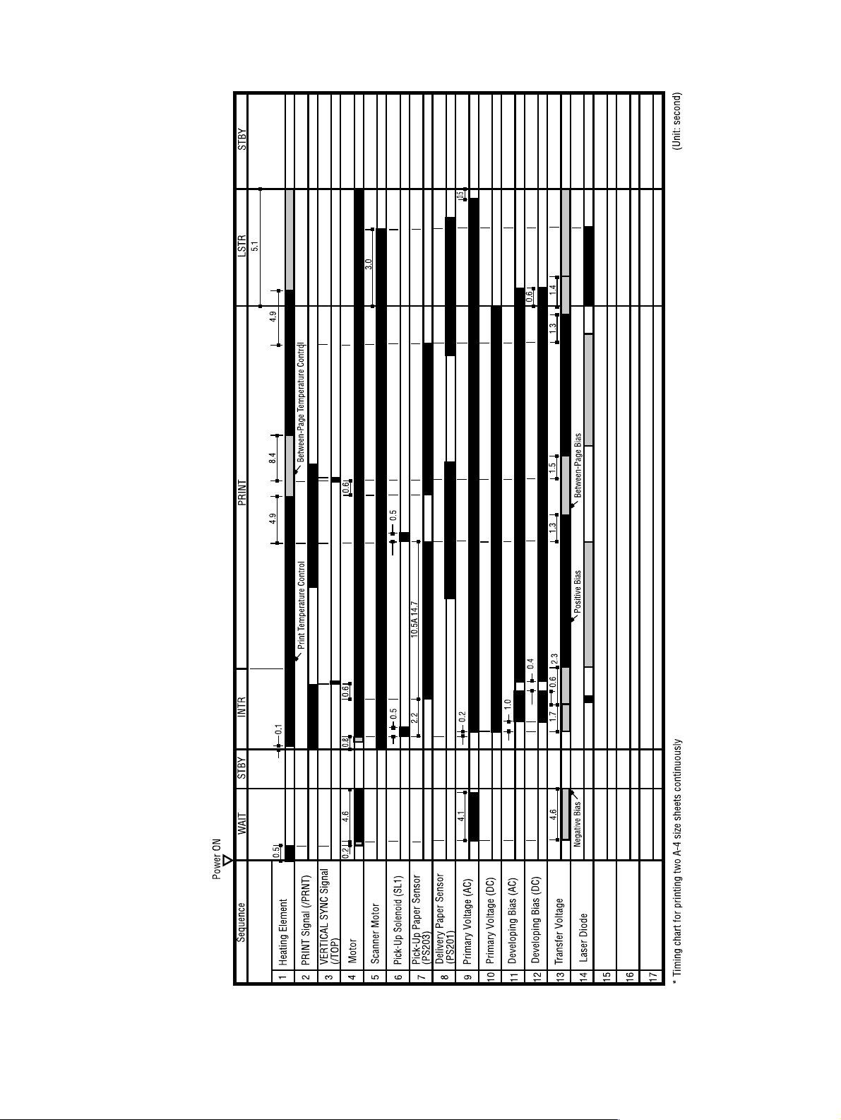
Figure 5-7 General timing diagram - HP LaserJet 5L
EN Basic sequence of operation 67
Page 70
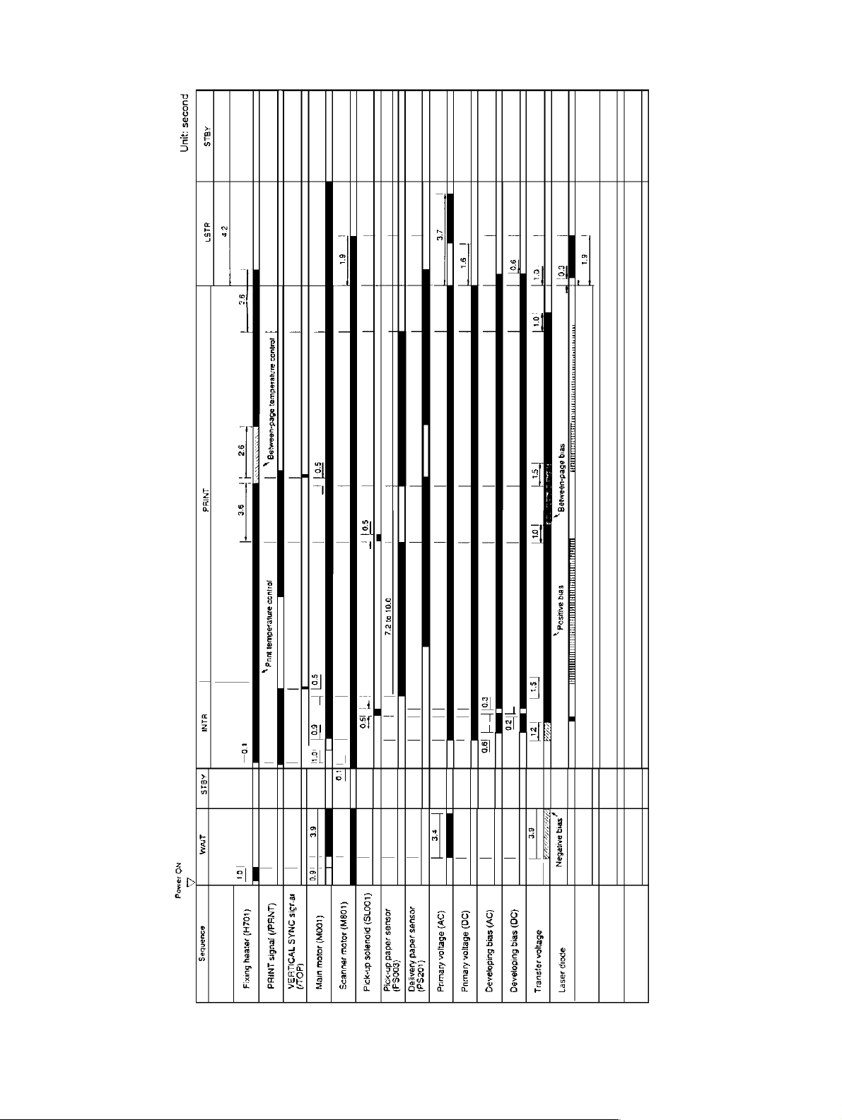
Figure 5-8 General timing diagram - HP LaserJet 6L and HP LaserJet 6L ProSL
68 Functional overview EN
Page 71

6 Removal and replacement
Chapter contents
Removal and replacement strategy. . . . . . . . . . . . . . . . . . . . . . . . . . . . . . . . . . . . . . . . . . . . . . . .70
Required tools . . . . . . . . . . . . . . . . . . . . . . . . . . . . . . . . . . . . . . . . . . . . . . . . . . . . . . . . . . . . . . . .71
Installing memory cards (DRAM) . . . . . . . . . . . . . . . . . . . . . . . . . . . . . . . . . . . . . . . . . . . . . . . . .72
Covers and doors . . . . . . . . . . . . . . . . . . . . . . . . . . . . . . . . . . . . . . . . . . . . . . . . . . . . . . . . . . . . . 73
Back Cover . . . . . . . . . . . . . . . . . . . . . . . . . . . . . . . . . . . . . . . . . . . . . . . . . . . . . . . . . . . . . . .73
EP Door Assembly . . . . . . . . . . . . . . . . . . . . . . . . . . . . . . . . . . . . . . . . . . . . . . . . . . . . . . . . . 75
Memory Door . . . . . . . . . . . . . . . . . . . . . . . . . . . . . . . . . . . . . . . . . . . . . . . . . . . . . . . . . . . . . 76
Main Cover and Paper Input Assembly. . . . . . . . . . . . . . . . . . . . . . . . . . . . . . . . . . . . . . . . . .77
Internal assemblies . . . . . . . . . . . . . . . . . . . . . . . . . . . . . . . . . . . . . . . . . . . . . . . . . . . . . . . . . . . .78
Control Panel . . . . . . . . . . . . . . . . . . . . . . . . . . . . . . . . . . . . . . . . . . . . . . . . . . . . . . . . . . . . .78
Exit Roller Assembly. . . . . . . . . . . . . . . . . . . . . . . . . . . . . . . . . . . . . . . . . . . . . . . . . . . . . . . .79
Delivery Assembly . . . . . . . . . . . . . . . . . . . . . . . . . . . . . . . . . . . . . . . . . . . . . . . . . . . . . . . . . 80
Fuser Pressure Plate . . . . . . . . . . . . . . . . . . . . . . . . . . . . . . . . . . . . . . . . . . . . . . . . . . . . . . .82
Heating Element . . . . . . . . . . . . . . . . . . . . . . . . . . . . . . . . . . . . . . . . . . . . . . . . . . . . . . . . . . . 84
Pressure Roller . . . . . . . . . . . . . . . . . . . . . . . . . . . . . . . . . . . . . . . . . . . . . . . . . . . . . . . . . . . .87
Face-Up/Face-Down Lever. . . . . . . . . . . . . . . . . . . . . . . . . . . . . . . . . . . . . . . . . . . . . . . . . . .88
Fuser Exit Roller Assembly. . . . . . . . . . . . . . . . . . . . . . . . . . . . . . . . . . . . . . . . . . . . . . . . . . . 89
Paper Exit Sensor Flag. . . . . . . . . . . . . . . . . . . . . . . . . . . . . . . . . . . . . . . . . . . . . . . . . . . . . .90
Top assemblies . . . . . . . . . . . . . . . . . . . . . . . . . . . . . . . . . . . . . . . . . . . . . . . . . . . . . . . . . . . . . . .91
Laser/Scanner Assembly . . . . . . . . . . . . . . . . . . . . . . . . . . . . . . . . . . . . . . . . . . . . . . . . . . . .91
Solenoid . . . . . . . . . . . . . . . . . . . . . . . . . . . . . . . . . . . . . . . . . . . . . . . . . . . . . . . . . . . . . . . . .92
Pickup Roller Assembly . . . . . . . . . . . . . . . . . . . . . . . . . . . . . . . . . . . . . . . . . . . . . . . . . . . . .94
Paper Feed Frame . . . . . . . . . . . . . . . . . . . . . . . . . . . . . . . . . . . . . . . . . . . . . . . . . . . . . . . . .97
Transfer Roller Guide and Transfer Roller. . . . . . . . . . . . . . . . . . . . . . . . . . . . . . . . . . . . . . .101
Kick Plate . . . . . . . . . . . . . . . . . . . . . . . . . . . . . . . . . . . . . . . . . . . . . . . . . . . . . . . . . . . . . . .102
Separation Pad . . . . . . . . . . . . . . . . . . . . . . . . . . . . . . . . . . . . . . . . . . . . . . . . . . . . . . . . . . .104
Subpads . . . . . . . . . . . . . . . . . . . . . . . . . . . . . . . . . . . . . . . . . . . . . . . . . . . . . . . . . . . . . . . . 105
Feed Assembly. . . . . . . . . . . . . . . . . . . . . . . . . . . . . . . . . . . . . . . . . . . . . . . . . . . . . . . . . . .106
Bottom assemblies . . . . . . . . . . . . . . . . . . . . . . . . . . . . . . . . . . . . . . . . . . . . . . . . . . . . . . . . . . . 109
Memory Door Guide . . . . . . . . . . . . . . . . . . . . . . . . . . . . . . . . . . . . . . . . . . . . . . . . . . . . . . .109
Motor. . . . . . . . . . . . . . . . . . . . . . . . . . . . . . . . . . . . . . . . . . . . . . . . . . . . . . . . . . . . . . . . . . . 110
DC Controller . . . . . . . . . . . . . . . . . . . . . . . . . . . . . . . . . . . . . . . . . . . . . . . . . . . . . . . . . . . . 111
Formatter PCA . . . . . . . . . . . . . . . . . . . . . . . . . . . . . . . . . . . . . . . . . . . . . . . . . . . . . . . . . . .114
EN Chapter contents 69
Page 72

Removal and replacement strategy
This chapter documents removal and replacement of Field Replaceable Units (FRUs) only.
Replacement is generally the reverse of removal. Occasionally , notes are included to provide
direction for difficult or critical replacement procedures.
WARNING! Unplug the power cord from the power outlet before attempting to service the printer. If this warning
is not followed, severe injury may result.
Never operate or service the printer with the protective cover removed from the Laser/Scanner
Assembly. The reflected beam, although invisible, can damage your eyes.
The sheet metal edges of this printer can be sharp! Exercise caution when working with the printer.
CAUTION The printer contains parts that are electrostatic discharge (ESD) sensitive. Always service printers at
an ESD-protected workstation .
To install a self-tapping screw, first turn it counter-clockwise to align it with the existing thread pattern,
then carefully turn clockwise to tighten. Do not overtighten. If a self-tapping screw-hole becomes
stripped, repair the screw-hole or replace the affected assembly.
Note Always remove the toner cartridge before removing or replacing parts.
70 Removal and replacement EN
Page 73

Required tools
l #2 Phillips scr ewdr iver with a magnetic tip
l small flathead screwdriver
l needlenos e plier s
CAUTION A PosiDriv screwdriver will damage the printer’s screw heads. Us e Phillips only.
Figure 6-1 shows the difference between a Phillips and a PosiDriv screwdriver. Note that a Phillips tip
has more beveled surfaces.
Phillips PosiDriv
Figure 6-1 Phillips and PosiDriv screwdrivers
EN Required t ools 71
Page 74
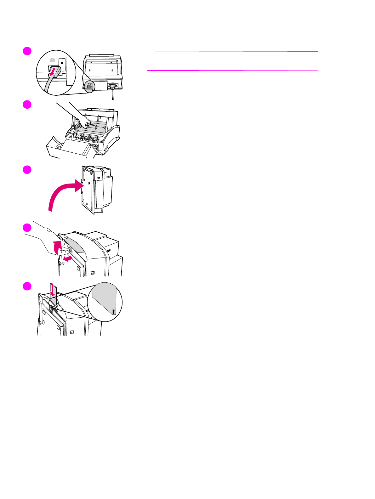
Installing memory cards (DRAM)
1
Note
The HP LaserJet 6L Pro does not support memory upgrades.
1 Unplug the power cord from the printer. You should not install a
memory card while the printer is in SleepMode.
2
3
4
2 Open the Printer Door, remove the toner cartridge, and close the
Printer Door. Protect the toner cartridge from light while you are
working on the printer.
3 Remove any paper in the paper tray. Gently tip the printer onto its
side so that the memory cover is on top as shown in Figure 3.
4 Remove the Memory Expansion Cover by carefully pulling the tab
out and away from the printer in a gentle rocking motion.
5 Align the memory card with the corner notch so it is positioned as in
Figure 4. Push it firmly into the printer
Replace the Memory Expansion Cover, set the printer upright, reinstall
the toner cartridge, reinsert paper, and reconnect to the power source.
Print a self-test page (see Chapter 3) to check that the printer
recognizes the additional memory you have added. Your Total Memory
in the “Printer Information” section will show the new MB total.
1 MB card 2 MB total
2 MB card 3 MB total
4 MB card 5 MB total
8 MB card 9 MB total
5
72 Removal and replacement EN
Page 75
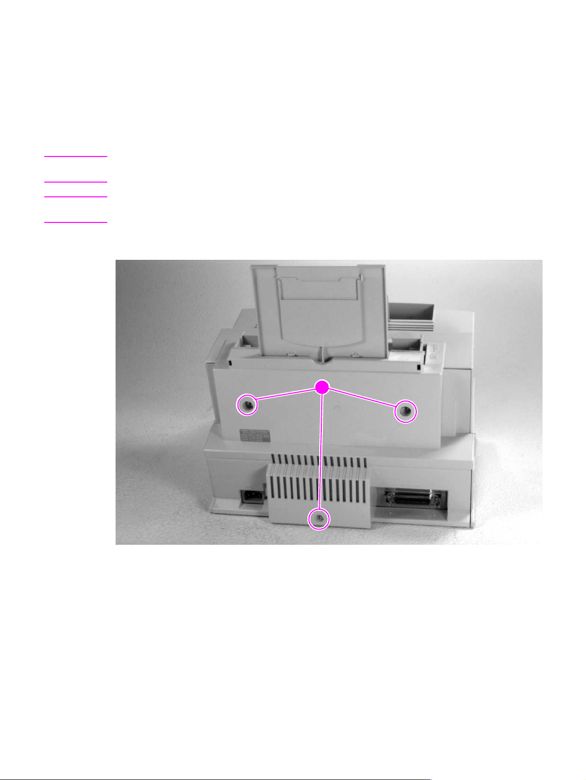
Covers and doors
Back Cover
1 Unplug the power cord and remove the parallel cable from the back of the printer.
2 Remove the toner cartridge.
3 Lift the Input Extender assembly.
CAUTION You must lift the Input Extender when the covers are removed or it will break. After you have removed
the covers, leave the Input Extender in this lifted position for ease of replacement.
Note The Input Extender for the HP LaserJet 6L Pro differs from the one shown in the photo. It does not
have the extra extender for legal-size paper.
4 Remove the (3) screws (Figure 6-2, callout 1).
Figure 6-2 Back Cover removal (1 of 2)
1
EN Covers and doors 73
Page 76
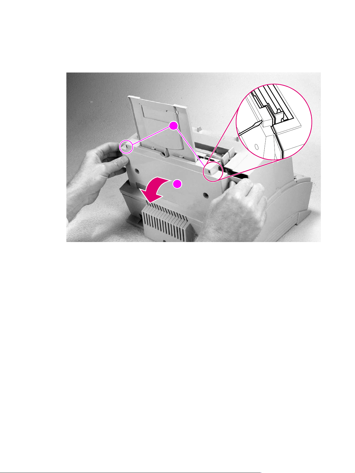
5 Separate the rear panel from the main cover , pulling the lower corners away from the printer first.
Then, insert the small flathead screwdriver into the openings at the top to pop the upper corners
(Figure 6-3, callout 1).
6 Remove the cover by grabbing it on both sides and pulling it straight back with a firm pull (Figure
6-3, callout 2).
1
2
Figure 6-3 Back Cover removal (2 of 2)
To reinstall
Make certain the Input Extender is raised before you reinstall the back cover.
74 Removal and replacement EN
Page 77

EP Door Assembly
1 Unplug the power cord and remove the parallel cable from the back of the printer.
2 Open the EP Door.
3 Remove the toner cartridge.
4 There is a flex point along the door hinge. Firmly press the left tab inward to release it (Figure 6-
4). The right tab will fall out easily.
Figure 6-4 EP Door Assembly removal
EN Covers and doors 75
Page 78

Memory Door
Note This procedure does not apply to the HP LaserJet 6L Pro. That model does not have a Memory Door.
1 Unplug the power cord and remove the parallel cable from the back of the printer.
2 Remove the toner cartridge.
3 Gently tip the printer onto its side so that the Control Panel is on top.
4 Carefully pull the door tab out (Figure 6-5, callout 1) and away from the printer in a gentle rocking
motion (Figure 6-5, callout 2).
Figure 6-5 Memory Door removal
2
1
76 Removal and replacement EN
Page 79
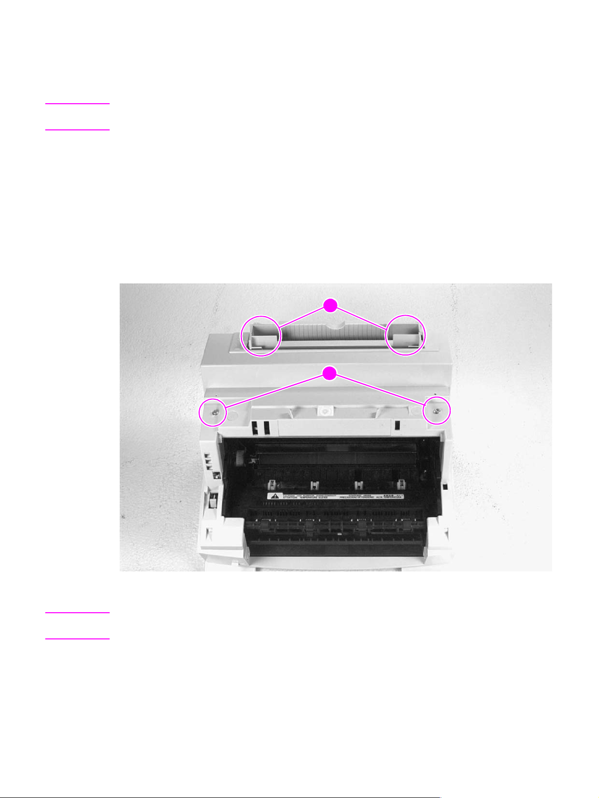
Main Cover and Paper Input Assembly
1 Remove the toner cartridge.
2 Remove memory door (HP LaserJet 5L and 6L).
CAUTION Remove the memory door first (HP LaserJet 5L and 6L). The door will break if you remove the Main
Cover without removing the memory door.
3 Remove the EP Door Assembly.
4 Remove the Back Cover.
5 Remove the (2) screws from the top of the printer (Figure 6-6, callout 1).
6 Grasp the two lower, front corners of the printer and pull gently outward to release the front of the
Main Cover.
7 Lift the cover straight off.
8 Remove the Paper Input Assembly (Figure 6-6, callout 2) by rotating it forward and lifting it out
with firm pressure.
2
1
Figure 6-6 Main Cover and Paper Input Assembly removal
Note When replacing the Paper Input Assembly, make certain that the mylar sheet is positioned between
the Input Feed Roller and Separation Pad and that the sheet is not folded or bent.
EN Covers and doors 77
Page 80
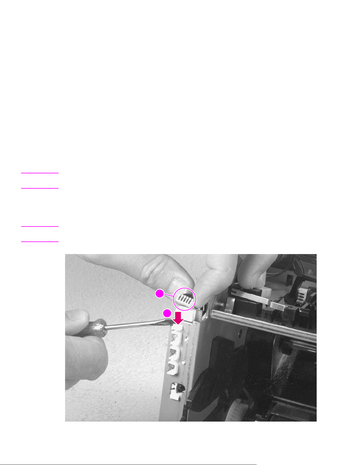
Internal assemblies
Control Panel
Procedure for HP LaserJet 5L and 6L
1 Remove the Printer Covers.
2 Use the needlenose pliers to release the Control Panel connector (Figure 6-7,callout 1).
3 Press the tab on the top of the Control Panel downward (Figure 6-7, callout 2). The Control Panel
will pop out of the printer chassis.
4 Lift the Control Panel out.
Procedure for HP LaserJet 6L Pro
1 Remove the Printer Covers.
2 Press the tab on the top of the Control Panel downward (Figure 6-7, callout 2). The Control Panel
will pop out of the printer chassis.
Note The Control Panel on the HP LaserJet 6L Pro is soldered directly to the wiring harness. It is not attached
with a connector. Do not try to separate the Control Panel from the wiring harness.
3 Press the tab on the top of the Control Panel downward (Figure 6-7, callout 2).The Control Panel
will pop out of the printer chassis.
4 Carefully remove the cable from the guides on the printer chassis.
Note The other end of the wiring harness is attached to the Formatter PCA with a connector. See “Formatter
PCA” later in this chapter for more information.
1
2
Figure 6-7 Control Panel removal
78 Removal and replacement EN
Page 81
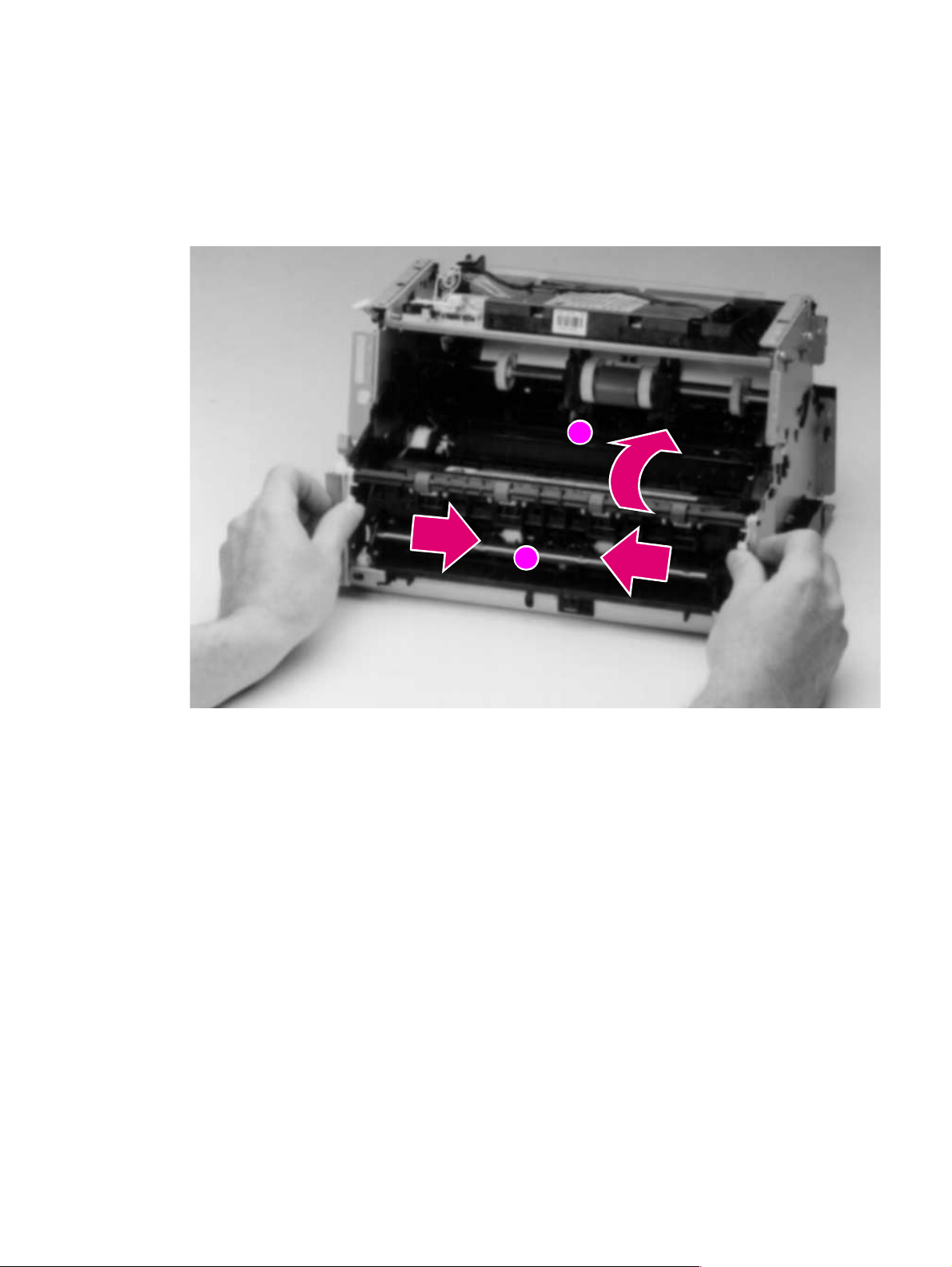
Exit Roller Assembly
1 Remove Printer Covers.
2 Grasp both tabs at the lower ends of the Exit Roller bushings and pull inward. This will release
the tabs from the printer chassis (Figure 6-8, callout 1).
3 Rotate the tabs 90 degrees, clear of the printer chassis (Figure 6-8, callout 2).
4 Lift the roller out.
2
Figure 6-8 Exit Roller removal
To reinstall
The end of the Exit Roller that has a gear attached must fit into the gear train. Although it is possible
to reinstall the Exit Roller so that the gear end is on the opposite side of the printer, this placement
would cause paper path problems.
1
EN Internal assemblies 79
Page 82
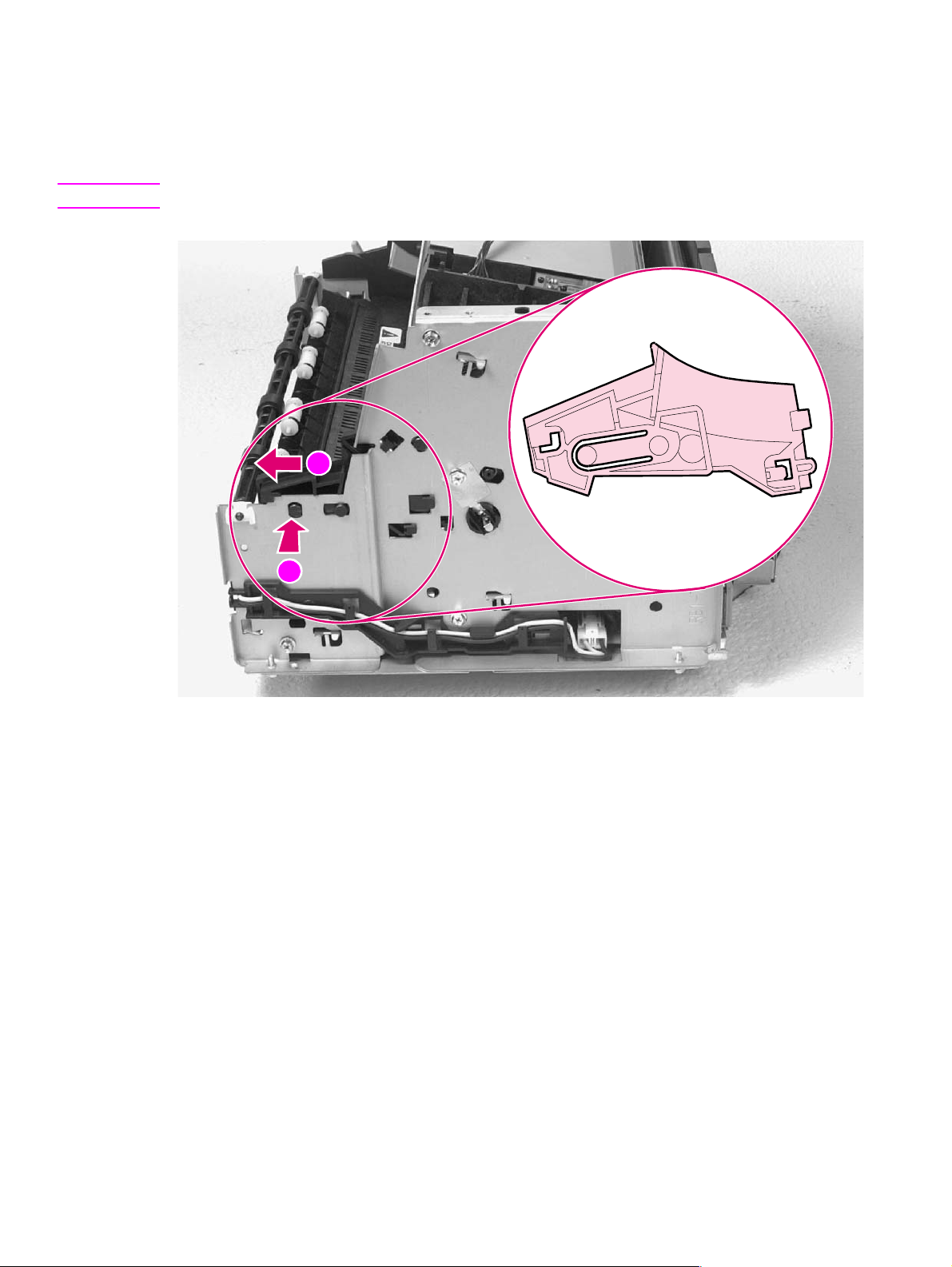
Delivery Assembly
1 Remove the Printer Covers and Exit Roller Assembly.
2 Remove the EP Right-hand assembly by pressing inward on the tab (Figure 6-9, callout 1) and
sliding the assembly toward the front of the printer (Figure 6-9, callout 2).
Note The EP Right-Hand assembly must be removed to access any fuser components.
2
1
Figure 6-9 Delivery Assembly removal (1 of 2)
80 Removal and replacement EN
Page 83
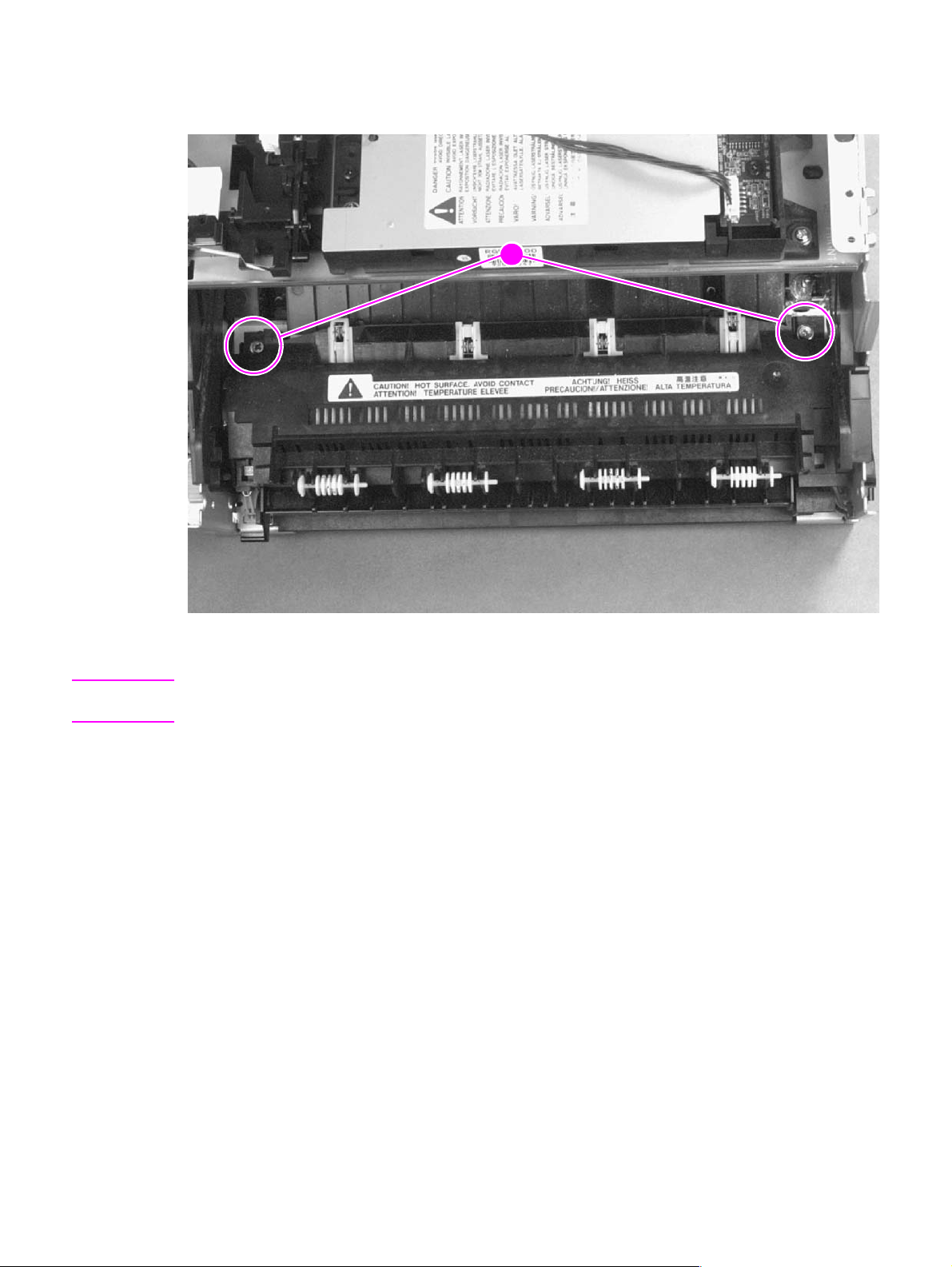
3 Use the magnetic screwdriver to remove the (2) screws (Figure 6-10, callout 1).
4 Rotate the rear of the Delivery Assembly up and forward, then lift it out of the printer.
1
Figure 6-10 Delivery Assembly removal (2 of 2)
Note When reinstalling the Delivery Assembly, make sure that the tabs on the front end of the Delivery
Assembly fit under the sheet metal fuser plate below.
EN Internal assemblies 81
Page 84
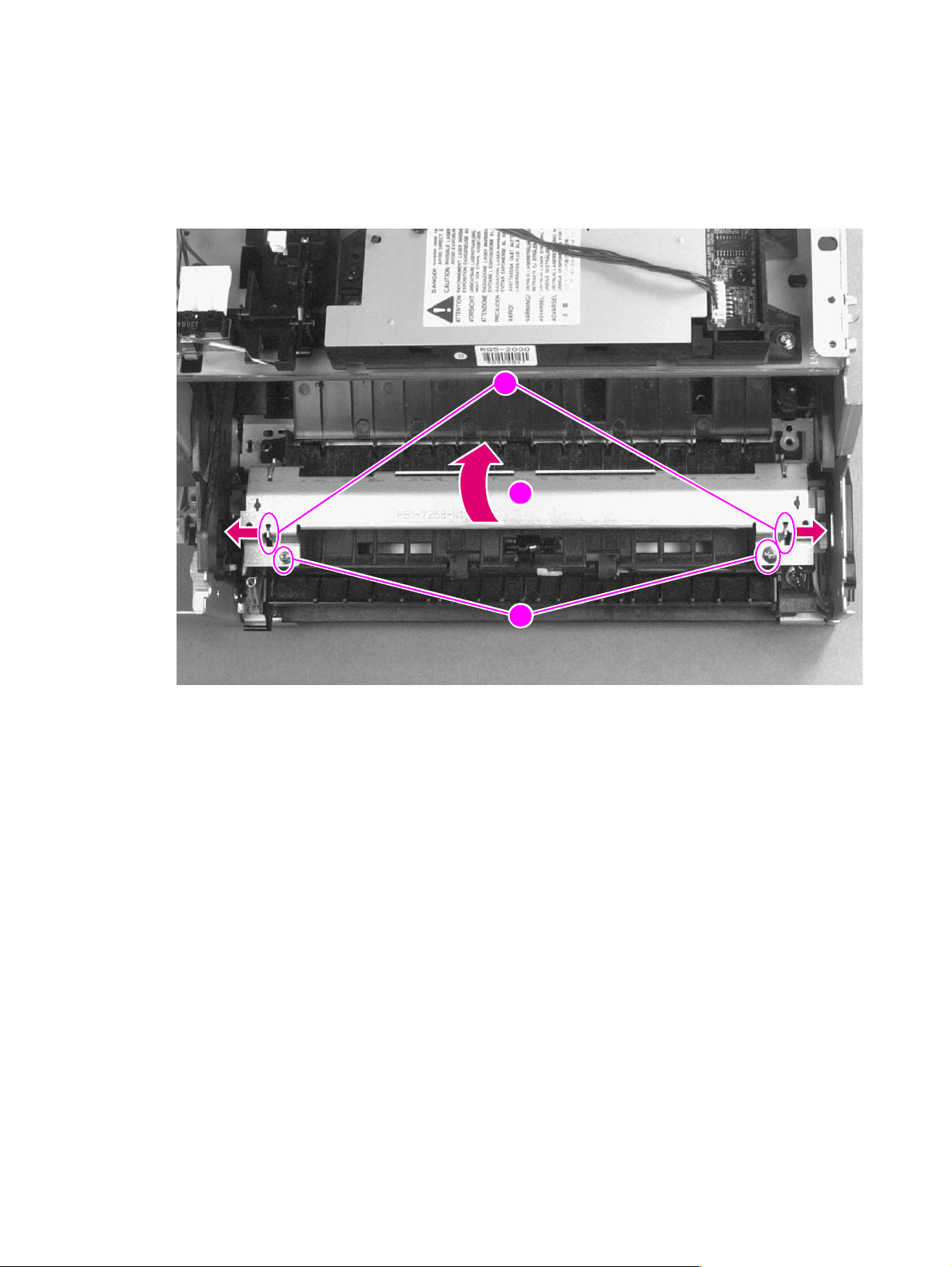
Fuser Pressure Plate
1 Remove Printer Covers and Delivery Assembly (Figures 6-9 and 6-10).
2 Remove the (2) screws (Figure 6-11, callout 1).
3 Press the Fuser Plate retainer clips out to release the Pressure Plate (Figure 6-11, callout 2).
4 Rotate the plate around and toward the back. Lift up to remove it (Figure 6-11, callout 3).
2
3
Figure 6-11 Fuser Pressure Plate removal
1
82 Removal and replacement EN
Page 85
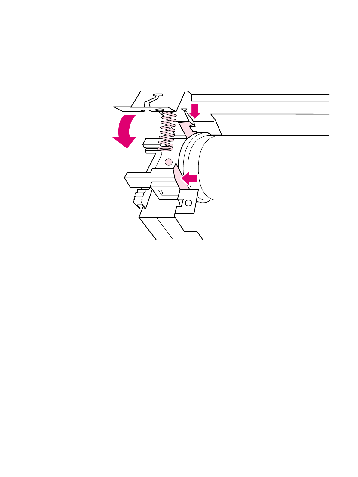
To reinstall
The Fuser Pressure Plate is kept in place by four locking mechanisms in each corner. Place the rear
slits in the plate over the rear brackets that hold the Fusing Assembly (Figure 6-12, callout 1). Lower
the plate over the retaining clips, pressing on both sides of the Fuser Pressure Plate (Figure 6-12,
callout, 2). It is important that the spring is placed over the positioning pin (callout 3) because
inadequate pressure will cause fusing problems. Replace the screws.
Figure 6-12 Fuser Pressure Plate replacement
EN Internal assemblies 83
Page 86
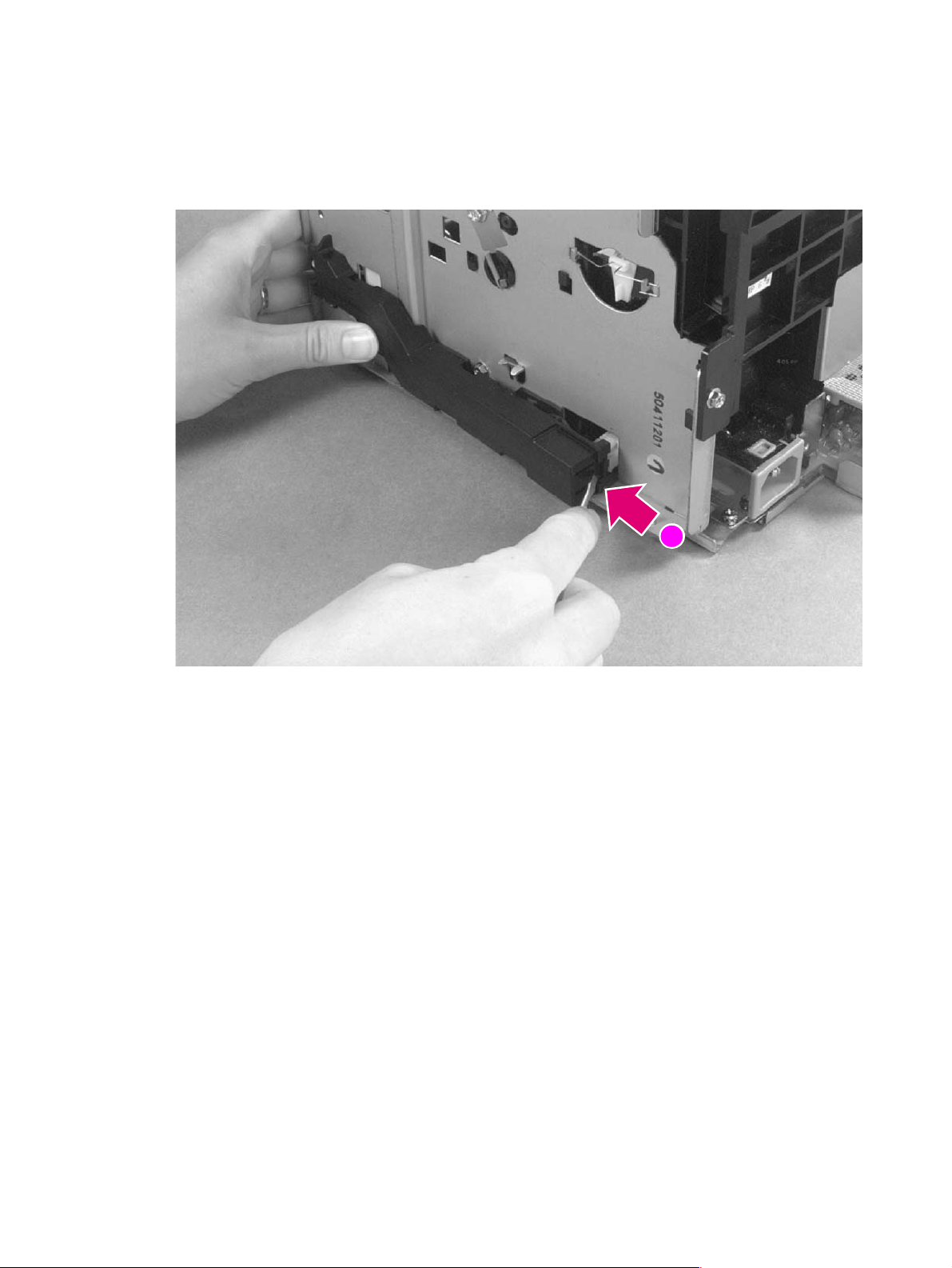
Heating Element
1 Remove Printer Covers, Delivery Assembly (Figures 6-9 and 6-10), and Fuser Pressure Plate
(Figure 6-11).
2 Remove the wire cover (on the right side of the printer) for the Heating Element wires by pressing
in on the tab and pulling outward (Figure 6-13, callout 1).
Figure 6-13 Heating Element remo val (1 of 3)
1
84 Removal and replacement EN
Page 87
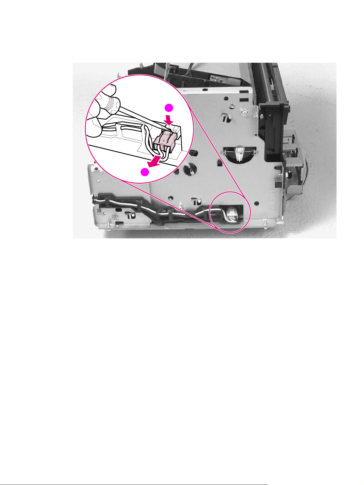
3 Disconnect the AC voltage to the Heating Element by releasing the connector located on the DC
Controller. Press down on the connector release with a small, flathead screwdriver (Figure 6-14,
callout 1). (Because this is a small space, it is much easier to reach the connector with a
screwdriver.) Pull straight out (Figure 6-14, callout 2).
1
2
Figure 6-14 Heating Element remo val (2 of 3)
EN Internal assemblies 85
Page 88
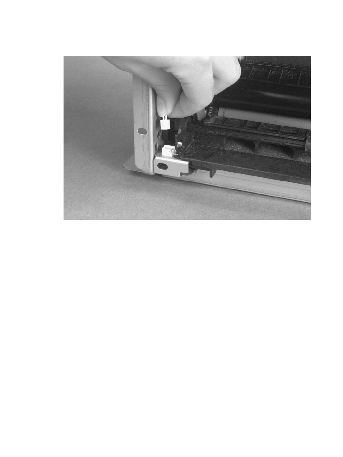
4 Remove the wire from the wire guides along the right-side of the printer.
5 Disconnect the thermistor feedback connector in the left front side of the Fusing Assembly
(Figure 6-15).
Figure 6-15 Heating Element remo val (3 of 3)
6 Lift the Heating Element out.
To reinstall
Make sure the connectors are properly reattached.
86 Removal and replacement EN
Page 89
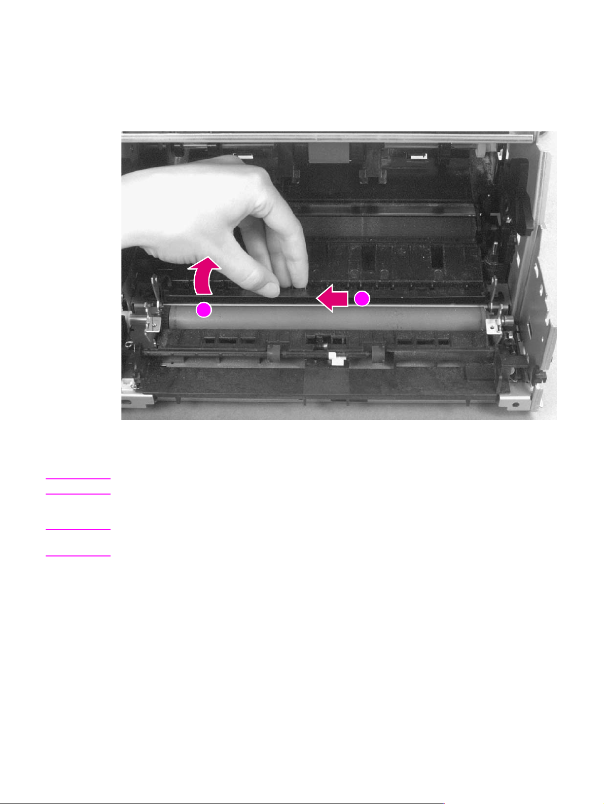
Pressure Roller
1 Remove Printer Covers, Delivery Assembly (Figures 6-9 and 6-10), Fuser Pressure Plate (Figure
6-11), and Heating Element (Figures 6-13 through 6-15).
2 Remove the Pressure Roller guide by lifting the edge (Figure 6-16, callout 1) and then rolling it
gently backward (Figure 6-16, callout 2).
1
2
Figure 6-16 Pressure Roller Guide removal
3 Lift the right end of the Pressure Roller up and out of the printer chassis.
Note The right end of the Pressure Roller is greased.
4 The left side will follow easily with the Pressure Roller gear still attached.
Note When reinstalling the Pressure Roller, apply a drop of grease to the grounding plate on the right side
of the shaft. (Refer to Chapter 8 for a part number.)
EN Internal assemblies 87
Page 90
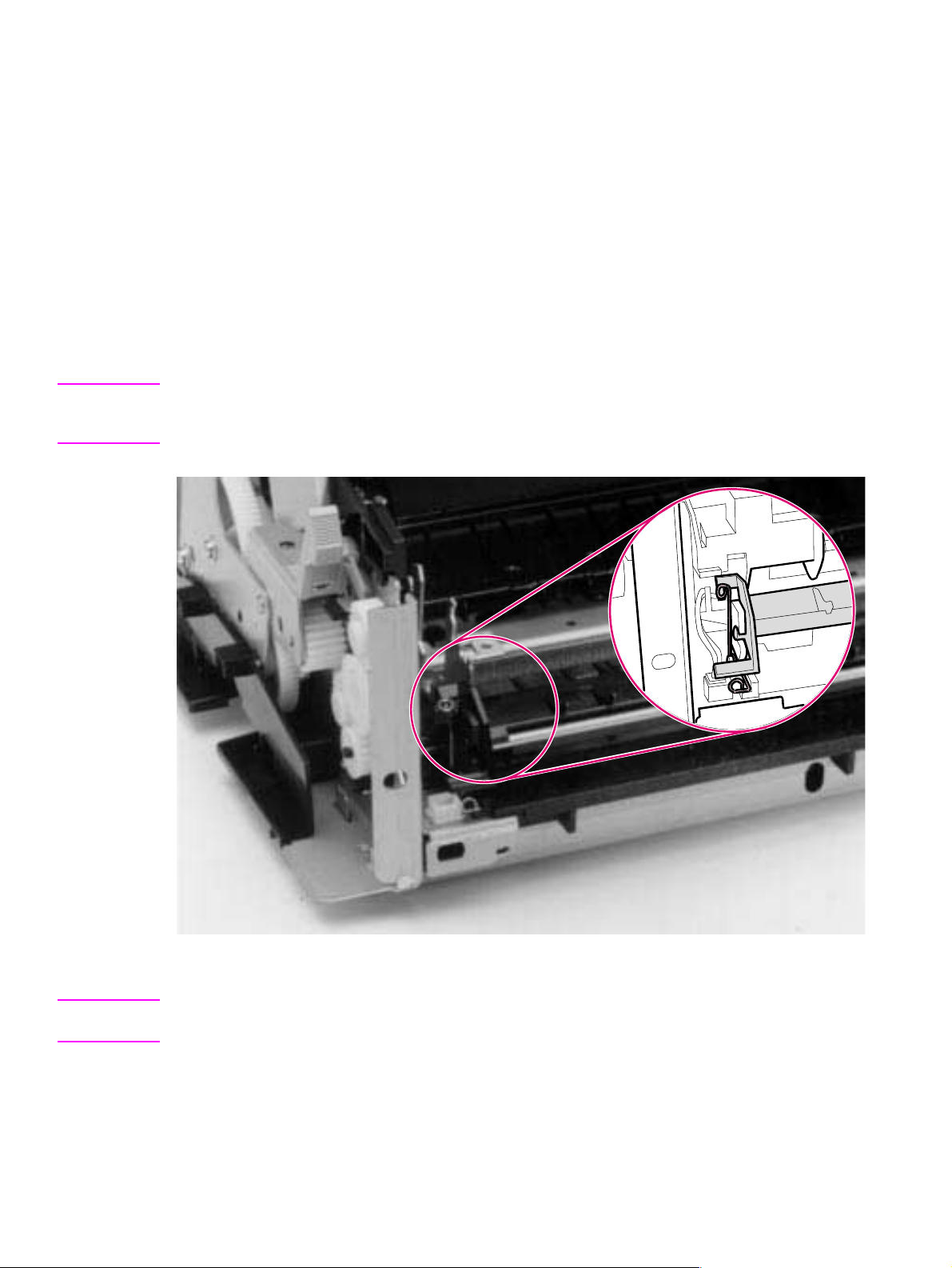
Face-Up/Face-Down Lever
1 Remove Printer Covers, Delivery Assembly (Figures 6-9 and 6-10), Fuser Pressure Plate (Figure
6-11), and Heating Element (Figures 6-13 through 6-15), and Pressure Roller (Figure 6-16).
2 Rotate the lever forward 90 degrees (past the spring) and pull it straight out the front of the
printer.
To reinstall
1 Make sure the lever arm is on the left and is initially pointing downward.
2 Pull the spring forward using needlenose pliers.
3 Slide the short, round tabs into the grooves on the Separation Guide Assembly. The machined
ridges on the lever will face you.
4 Release the spring so it falls in place in front of the square tab (Figure 6-17).
Note While the shape of the lever was changed for the HP LaserJet 6L (a stiffening rod was also added),
these procedures for Face-Up/Face-Down Lever removal remain unchanged. Figure 6-17 shows the
lever from an HP LaserJet 5L.
Figure 6-17 Face-Up/Face-Down Lever replacement
Note You can tell when the lever is in place because there are two plastic grooves that fit precisely in front
of the Exit Rollers, and you should be able to feel the spring’s release mechanism.
88 Removal and replacement EN
Page 91

Fuser Exit Roller Assembly
1 Remove Printer Covers, Delivery Assembly (Figures 6-9 and 6-10), Fuser Pressure Plate (Figure
6-11), and Heating Element (Figures 6-13 through 6-15), Pressure Roller (Figure 6-16), and
Face-Up/Face-Down Lever (Figure 6-17).
2 Remove the gear from the left end of the roller shaft by pressing down on the catching
mechanism with the small flathead screwdriver and pulling the gear away.
3 Remove the Exit Roller Assembly by pressing the small, white tab upward (Figure 6-18, callout 1)
and rotating it around (Figure 6-18, callout 2).
Note While the shape of the white tab was changed for the HP LaserJet 6L, these procedures for Fuser Exit
Roller Assembly removal remain unchanged. Figure 6-18 shows the white tab from an HP LaserJet 5L.
4 Slide the Exit Roller Assembly forward and out to the right of the printer.
Figure 6-18 Fuser Exit Roller removal
2
1
EN Internal assemblies 89
Page 92
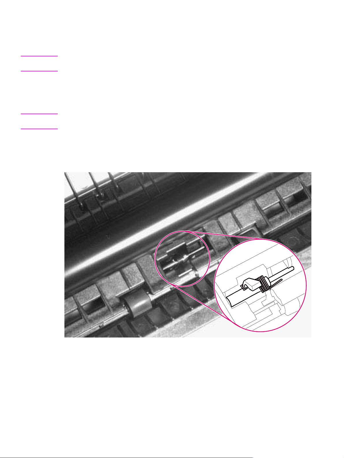
Paper Exit Sensor Flag
1 Remove the Printer Covers, Delivery Assembly (Figures 6-9 and 6-10), and Fuser Pressure
Plate (Figure 6-11).
CAUTION Before proceeding to Step 2, examine the Paper Exit Sensor flag. It is important to note the position
of the spring mechanism on the flag. The spring must be reinstalled to exactly this position.
2 Remove the Paper Exit Sensor flag by pressing down on the left side and pulling up on the right
side.
To reinstall
Note It is important that you reinstall the flag correctly , because installing it incorrectly will cause the Control
Panel to display an error with the Paper Exit Sensor (PS201).
Place the left side of the flag in the correct position first, then slide the right side into place, making
certain the spring is on top of the flag (Figure 6-19). If the spring exerts no pressure on the flag, it
may require “re-springing” by giving the spring an extra turn before reinstalling. The flag should fit
snugly in place.
Figure 6-19 Paper Exit Sensor Flag replacement
90 Removal and replacement EN
Page 93

Top assemblies
Laser/Scanner Assembly
1 Remove the Printer Covers.
2 Remove both Laser/Scanner connectors (Figure 6-20, callout 1).
Note The Laser/Scanner connect cable on the HP LaserJet 6L Pro is twisted (not shown in Figure 6-20).
3 Remove all (4) screws and lift the assembly straight off (Figure 6-20, callout 2).
Note One of the four screws is longer than the other three. Upon reinstallation, the longer screw must be
replaced in its original location.
2
1
Figure 6-20 Laser/Scanner Assembly removal
To reinstall
The Laser/Scanner connect cable on the HP LaserJet 6L Pro should be twisted before reinstalling
(not shown in Figure 6- 20).
1
EN T op assemblies 91
Page 94
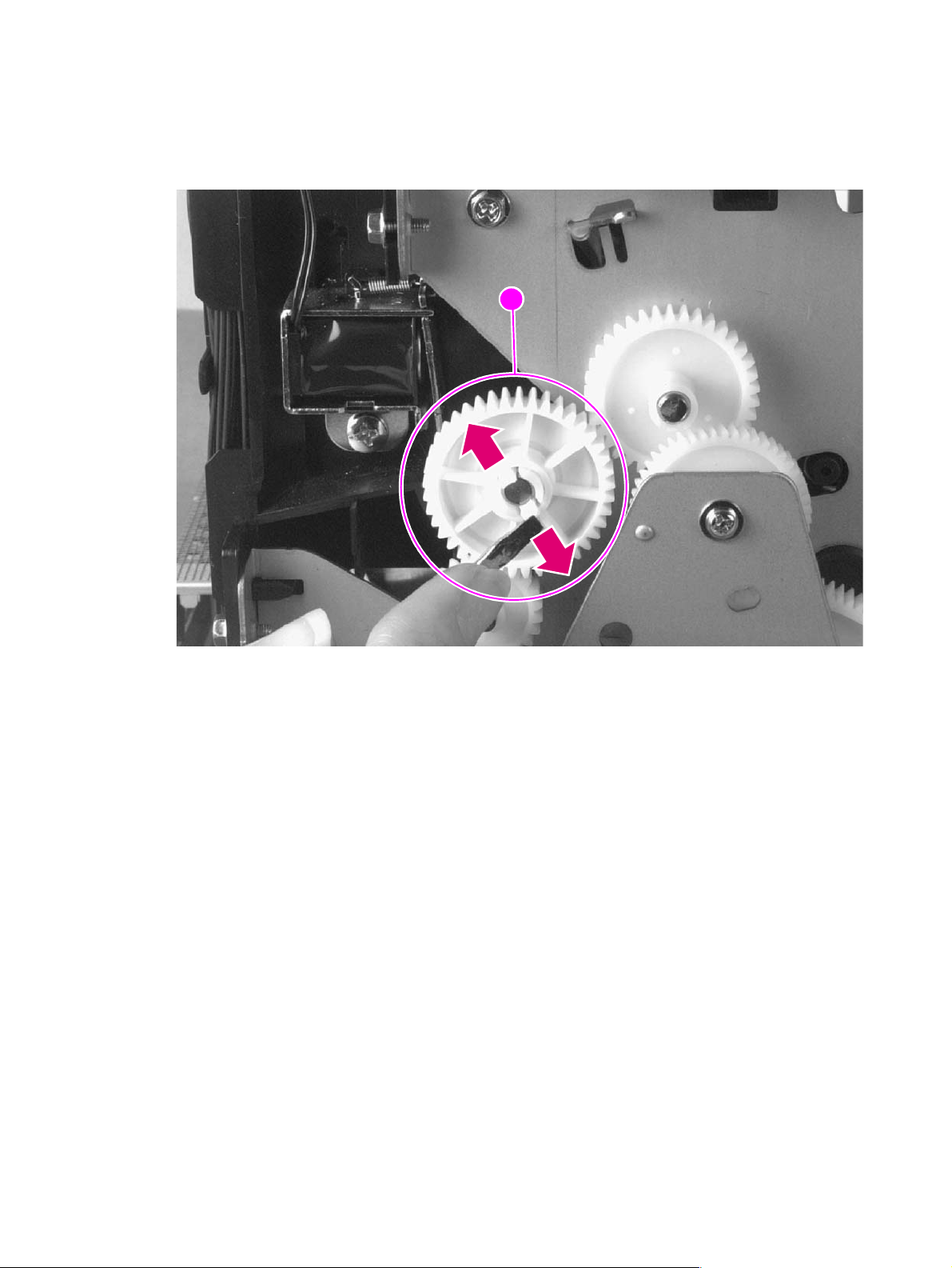
Solenoid
1 Remove the Printer Covers.
2 On the left side of the printer, remove the paper pickup gear (Figure 6-21, callout 1) by pressing
the tabs in the center of the gear outward and pulling the gear off (Figure 6-21).
1
Figure 6-21 Solenoid removal (1 of 2)
92 Removal and replacement EN
Page 95
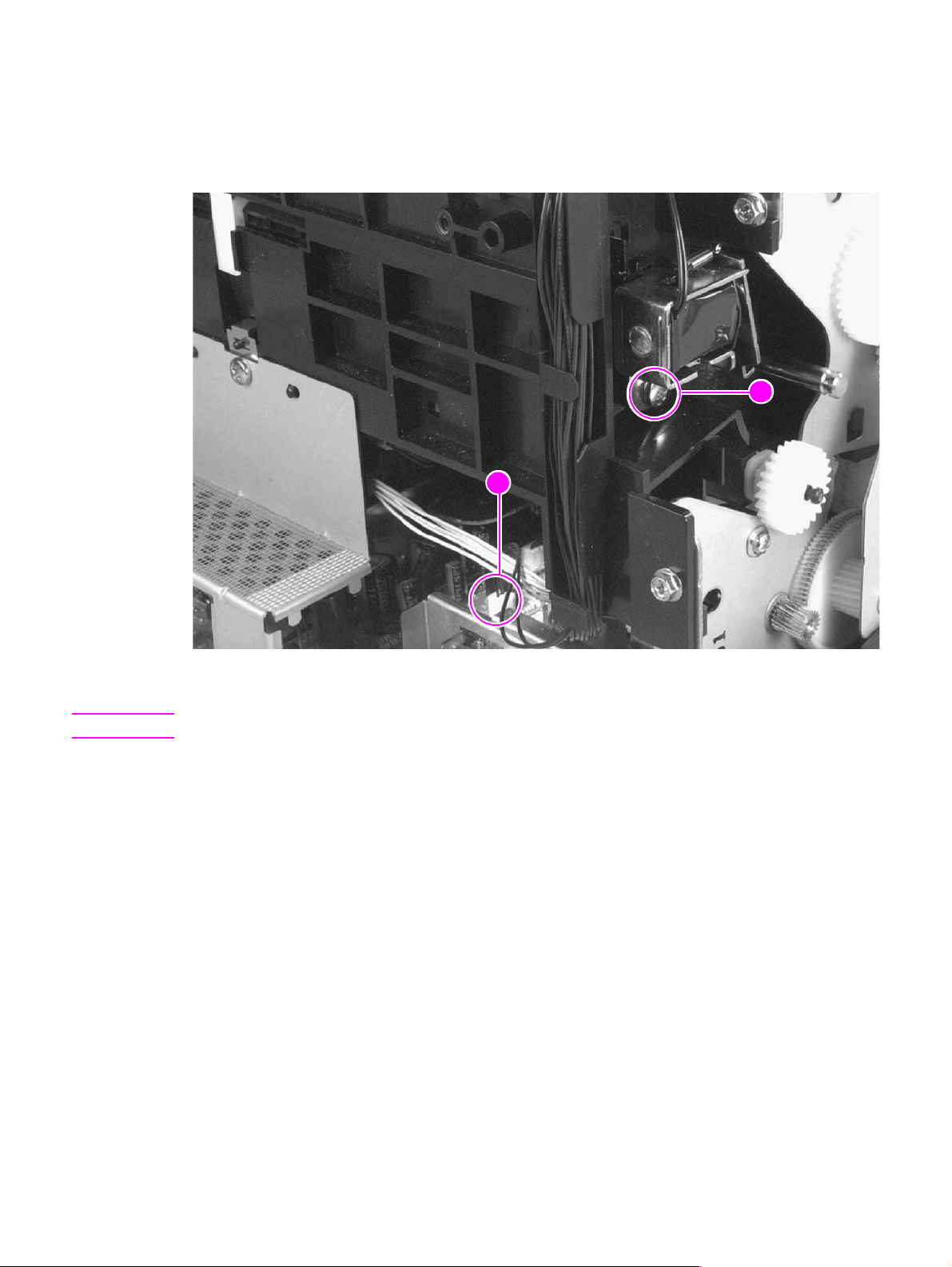
3 Remove the Solenoid connector (J204) from the DC Controller (Figure 6-22, callout 1).
4 Remove the self-tapping screw that holds the Solenoid in place (Figure 6-22, callout 2).
5 Unthread the wires from the printer chassis.
6 Lift the Solenoid off.
2
1
Figure 6-22 Solenoid removal (2 of 2)
Note When reinstalling this part, the Paper Pickup Gear is keyed to go on the shaft in only one way.
EN T op assemblies 93
Page 96
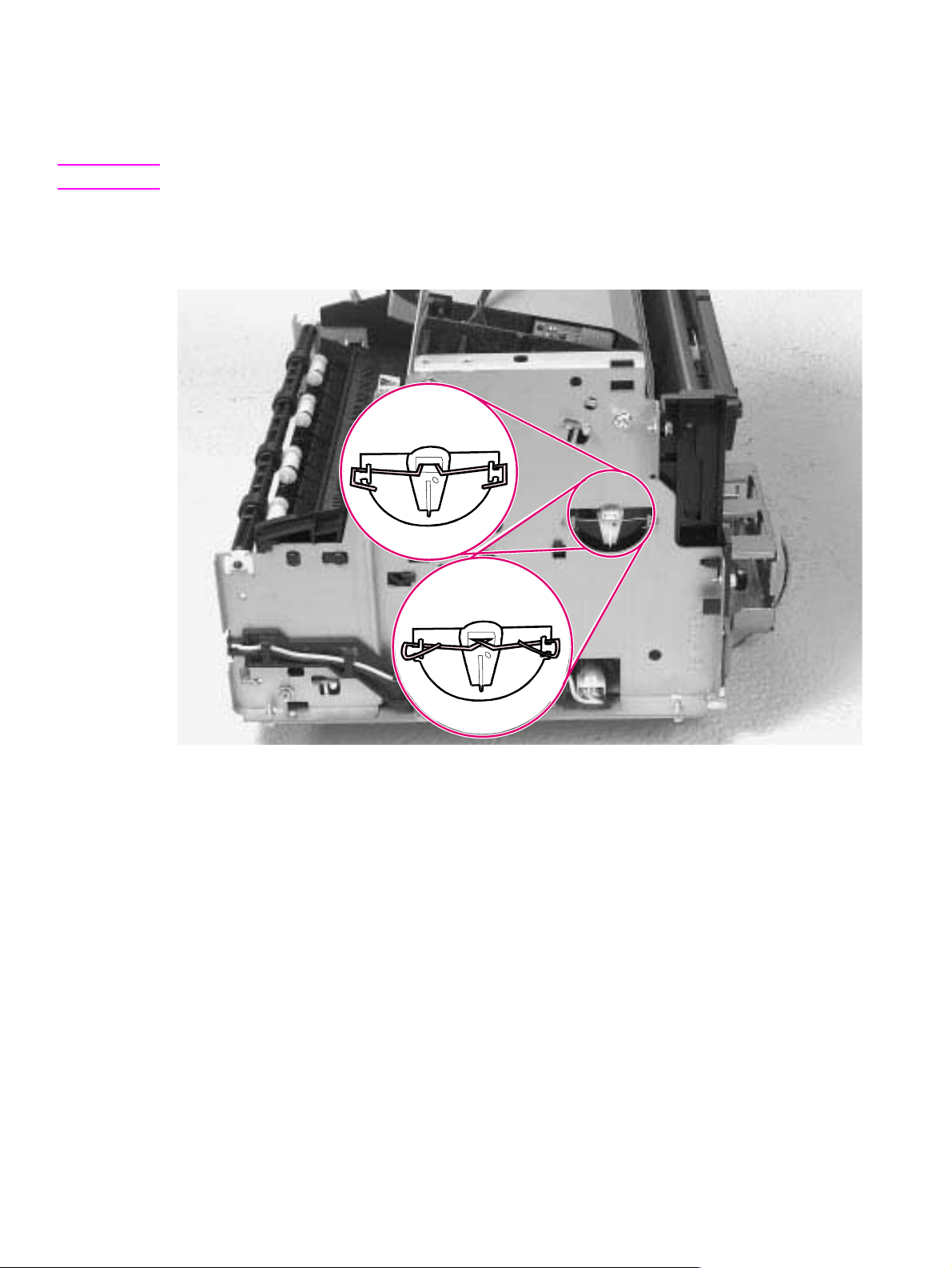
Pickup Roller Assembly
1 Remove the Printer Covers.
2 Remove the paper pickup gear (Figure 6-21).
Note This gear is keyed to go on the shaft in only one way.
3 Remove the pickup roller grounding clip on the right of the printer by lifting each end of the clip up
and over the two metal guides and sliding the clip off. Figure 6-23 depicts the clip from an HP
LaserJet 5L. The clip from an HP LaserJet 6L (and some HP LaserJet 5Ls) is shaped differently.
5L
6L/6L Gold/ 6L Pr o
(and some 5Ls)
Figure 6-23 Pickup Roller Assembly removal (1 of 2)
94 Removal and replacement EN
Page 97
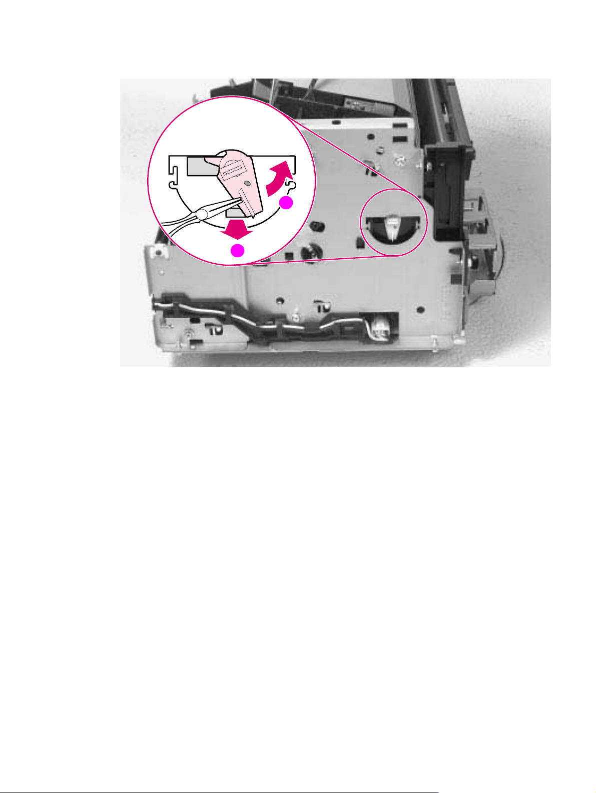
4 Using needlenose pliers, pull the bottom of the bushing out (Figure 6-24, callout 1), then turn it
counter clockwise to release it (Figure 6-24, callout 2).
2
1
Figure 6-24 Pickup Roller Assembly removal (2 of 2)
5 Lift the bushing out.
6 From inside the front of the printer, slide the right side of the Pickup Roller Assembly forward,
then lift the left side out.
EN T op assemblies 95
Page 98

To reinstall
After placing the Pickup Roller shaft through on the left side, line up the Idler Roller tabs while
repositioning the right side. Rock the shaft back and forth until the Pickup Roller and the Idler Roller
tabs are cor rectly reinstalled.
Note It is important that the Pickup Roller is placed back in with the two Idler Roller tabs up, so that they fit
into the underside of the metal chassis behind the Laser/Scanner assembly (Figure 6-25).
Figure 6-25 Paper Pickup Roller Assembly replacement (inside/front view)
96 Removal and replacement EN
Page 99
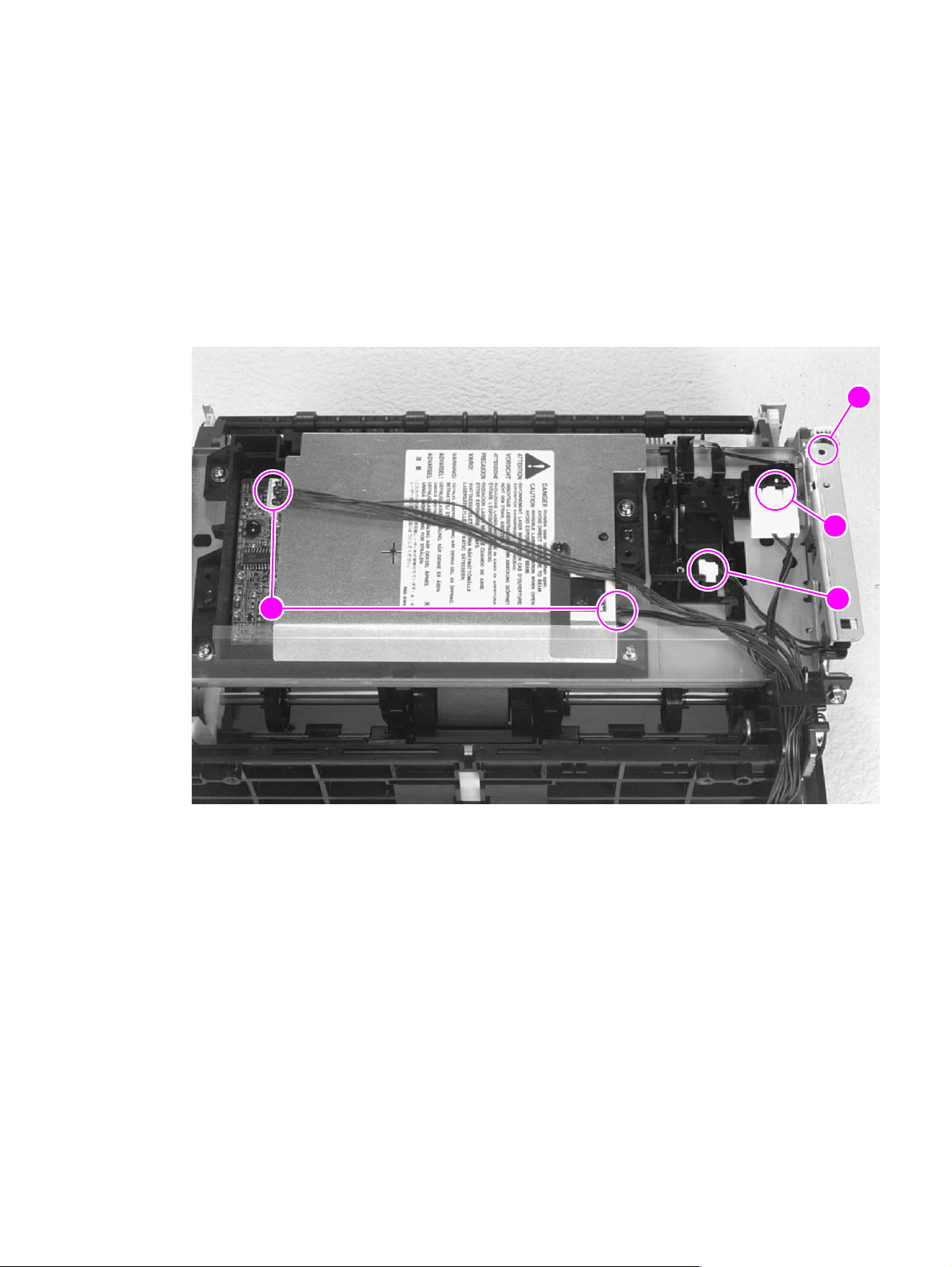
Paper Feed Frame
1 Remove the Printer Covers.
2 Remove the Pickup Roller Assembly (Figures 6-23 through 6-24).
3 Disconnect the following:
• Solenoid from the DC Controller at J204 (Figure 6-22, callout 1)
• Two connectors from the Laser/Scanner (Figure 6-26, callout 1)
• Connector from Top Cover/EP Cartridge Sensor on HP LaserJet 5L only (Figure 6-26, callout
2)
• Connector from Switch 101 (Figure 6-26, callout 3)
• Connector from Front Control Panel (Figure 6-26, callout 4)
4
3
1
Figure 6-26 Paper Feed Frame removal (1 of 4)
2
EN T op assemblies 97
Page 100
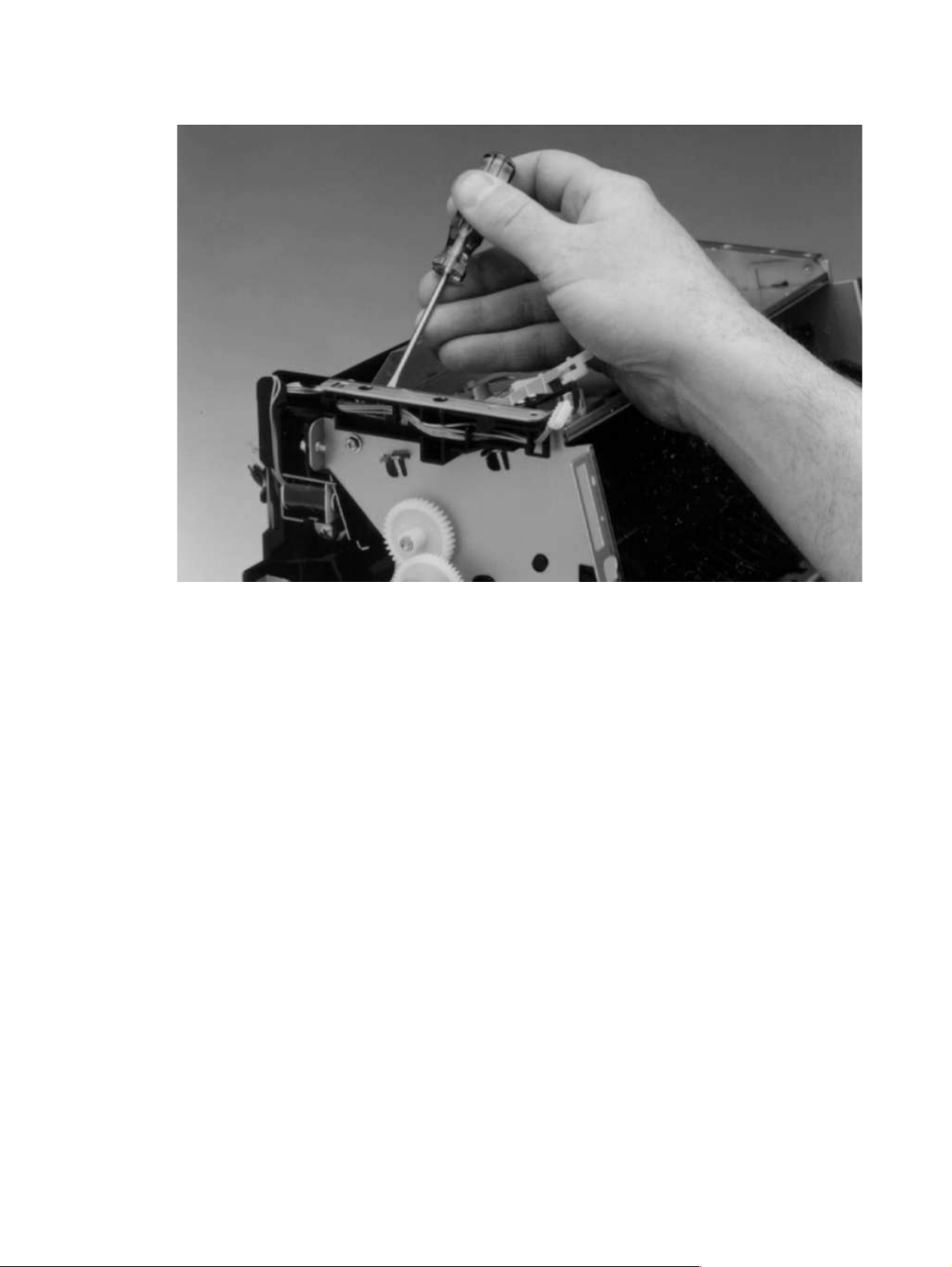
4 Release the catch on the control panel cable guide by using the small flathead screwdriver to
push on the tab (Figure 6-27). Then slide the guide off.
Figure 6-27 Paper Feed Frame removal (2 of 4)
98 Removal and replacement EN
 Loading...